


 Loading...
Enclosure cooling unit
3302.xxx |
3328.xxx |
3302.3xx |
3329.xxx |
3303.xxx |
3332.xxx |
3304.xxx |
3361.xxx |
3305.xxx |
3366.xxx |
Assembly and operating instructions

Contents
Contents |
|
|
EN |
|
|
1 |
Notes on documentation .................. |
3 |
1.1 |
CE labelling .................................................. |
3 |
1.2 |
Storing the documents................................. |
3 |
1.3Symbols used in these operating instructions 3
1.4 |
Other applicable documents ........................ |
3 |
2 |
Safety notes ..................................... |
3 |
3 |
Device description ............................ |
4 |
3.1TÜV-tested output measurement to
|
|
DIN EN 14511 .............................................. |
4 |
3.2 |
|
Functional description .................................. |
4 |
3.2.1 |
How it works ......................................................... |
4 |
|
3.2.2 |
Control .................................................................. |
5 |
|
3.2.3 Bus mode (e-Comfort controller only) .................... |
5 |
||
3.2.4 |
Safety devices ....................................................... |
5 |
|
3.2.5 |
Condensation ....................................................... |
5 |
|
3.2.6 |
Filter mats ............................................................. |
5 |
|
3.2.7 |
Door limit switch ................................................... |
5 |
|
3.2.8 |
Additional interface X3 .......................................... |
6 |
|
3.3 |
Proper use, foreseeable misuse ................... |
6 |
|
3.4 |
|
Scope of supply........................................... |
6 |
4 |
|
Assembly and connection ................ |
6 |
4.1 |
Choosing the installation site........................ |
6 |
|
4.2 |
|
Notes on assembly ...................................... |
6 |
4.2.1 |
General ................................................................. |
6 |
|
4.2.2 Layout of the electronic components in the |
|
||
|
|
enclosure .............................................................. |
7 |
4.3 |
Fitting the cooling unit .................................. |
7 |
|
4.3.1 |
Making the cut-outs .............................................. |
8 |
|
4.3.2 External mounting of the cooling unit ..................... |
8 |
||
4.3.3 Partial internal mounting of the cooling unit ........... |
8 |
||
4.3.4 Full internal mounting of the cooling unit ................ |
9 |
||
4.4 |
Connecting the condensate discharge ....... |
10 |
|
4.5 |
Notes on electrical installation .................... |
11 |
|
4.5.1 |
Connection data ................................................. |
11 |
|
4.5.2 Overvoltage protection and supply line load ........ |
11 |
||
4.5.3 |
Three-phase devices ........................................... |
11 |
|
4.5.4 |
Door limit switch ................................................. |
11 |
|
4.5.5 Notes on the flicker standard .............................. |
11 |
||
4.5.6 |
Potential equalisation .......................................... |
12 |
|
4.6 |
Making the electrical connection ................ |
12 |
|
4.6.1 Bus connection (only when interconnecting several
|
units with a Comfort controller) ............................ |
12 |
4.6.2 Connection X3 for serial interface ........................ |
12 |
|
4.6.3 |
Mounting external transformer ............................. |
12 |
4.6.4 Installing the power supply .................................. |
13 |
|
4.7 |
Finalising assembly .................................... |
15 |
4.7.1 |
Installing the filter media ...................................... |
15 |
4.7.2 Fitting the cooling unit ......................................... |
15 |
|
4.7.3 |
Setting the filter mat monitor (only with e-Comfort |
|
|
controller) ............................................................ |
16 |
6 |
Operation ....................................... |
16 |
6.1 Control using the Basic controller............... |
16 |
|
6.1.1 |
Properties ........................................................... |
16 |
6.1.2 |
Operating and error display ................................. |
17 |
6.1.3 |
Test mode with the Basic controller .................... |
18 |
6.1.4 |
Setting the temperature ...................................... |
18 |
6.1.5 |
Resetting the Basic controller .............................. |
18 |
6.2 Control using the e-Comfort controller........ |
18 |
|
6.2.1 |
Properties ........................................................... |
19 |
6.2.2 |
Eco mode ........................................................... |
19 |
6.2.3 |
Launching test mode .......................................... |
19 |
6.2.4 |
General information about programming ............. |
20 |
6.2.5 |
Editable parameters ............................................ |
21 |
6.2.6 |
Programming overview ....................................... |
22 |
6.2.7 |
Defining system messages for evaluation ............ |
23 |
6.2.8 |
Setting the master/slave identifier ........................ |
24 |
6.2.9 |
Evaluating system messages .............................. |
24 |
6.2.10 |
Reset the e-Comfort controller ............................ |
26 |
7 |
Inspection and maintenance .......... |
26 |
7.1Compressed air cleaning 3304.xxx,
3305.xxx .................................................... |
26 |
7.2Compressed air cleaning 3328.xxx,
3329.xxx, 3332.xxx .................................... |
30 |
7.3Installation instructions for NEMA 4X
|
devices ...................................................... |
35 |
8 |
Storage and disposal ..................... |
36 |
9 |
Technical details ............................ |
36 |
9.1 |
Technical specifications.............................. |
36 |
9.2 |
Performance diagrams ............................... |
43 |
10 |
List of spare parts .......................... |
44 |
11 |
Appendix ....................................... |
47 |
11.1 |
Cut-out and hole sizes ............................... |
47 |
11.1.1 Dimensions for external mounting ....................... |
47 |
|
11.1.2 Dimensions for partial internal mounting .............. |
50 |
|
11.1.3 Dimensions for full internal mounting ................... |
51 |
|
11.2 |
Electrical wiring plan................................... |
52 |
5 |
Start-up .......................................... |
16 |
2 |
Rittal enclosure cooling unit |

1 Notes on documentation
1Notes on documentation
1.1CE labelling
Rittal GmbH & Co. KG confirms the conformity of the cooling unit with the European Union's Machinery Directive 2006/42/EC and EMC Directive 2014/30/EC. A corresponding declaration of conformity has been issued. This can be found at the end of this document, or on the Rittal homepage.
1.2Storing the documents
The assembly and operating instructions as well as all other applicable documents are an integral part of the product. They must be issued to everyone who works with the unit and must always be available and on hand for operating and maintenance personnel.
1.3Symbols used in these operating instructions
The following symbols are used in this documentation:
Danger!
A dangerous situation in which failure to comply with the instructions will result in death or severe injury.
Warning!
A dangerous situation which may cause death or serious injury if the instructions are not followed.
Caution!
A dangerous situation which may lead to (minor) injuries if the instructions are not followed.
Note:
Important notices and indication of situations which may result in material damage.
This symbol indicates an "action point" and shows that you should perform an operation or procedure.
1.4Other applicable documents
Assembly and operating instructions in paper and digital format are available for the unit types described here. We cannot accept any liability for damage associated with failure to observe these instructions. Where applicable, the instructions for any accessories used also apply.
2 Safety notes
Please observe the following general safety notes when |
EN |
|
|
assembling and operating the unit: |
|
–Assembly, installation and servicing may only be performed by properly trained specialists.
–Screw the enclosure to the floor to prevent it from tipping over when the cooling unit is installed.
–Do not obstruct the air inlet and air outlet of the cooling unit inside and outside the enclosure (see sec-
tion 4.2.2 "Layout of the electronic components in the enclosure").
–To ensure problem-free opening and closing of the enclosure door, use a ride-up door roller (refer to the accessories in the Rittal Catalogue). This raises the door slightly and balances out the weight of the cooling unit, to prevent buckling of the door and associated seal problems.
–The heat loss of the components installed in the enclosure must not exceed the useful cooling power of the cooling unit.
–Cooling units with item numbers: 3303.xxx, 3361.xxx, 3304.xxx, 3305.xxx, 3328.xxx, 3329.xxx and 3332.xxx must be transported in an upright position and protected from tipping over.
–Units with item numbers 3302.xxx and 3366.xxx must be transported lying flat.
–Shipping braces must be used when transporting a unit that has already been mounted (on the enclosure). A wooden structure made from square timbers or boards to support the cooling unit at the bottom (see fig. 1) is suitable for this purpose. The pallet should be big enough to prevent the enclosure and cooling unit overturning. If the cooling unit is mounted on a door, ensure the door is kept closed during transport.
–Use only original spare parts and accessories
–Do not make any changes to the cooling unit other than those described in these instructions or associated instructions.
–Risk of burns! On cooling units with automatic condensate evaporation, the surface of the thermal element will get very hot during operation, and will remain so for some time afterwards.
–The mains connector of the cooling unit must only be connected and disconnected with the system de-en- ergised. Connect the protective device specified on the rating plate.
Rittal enclosure cooling unit |
3 |

3 Device description
EN
Enclosure |
Cooling unit |
|
Support
Fig. 1: Transporting an enclosure/cooling unit combination
3Device description
Depending on the model chosen, your cooling unit may vary in appearance from the illustrations contained in these instructions. However, the functions are identical in principle.
|
8 |
|
1 |
9 |
|
|
||
2 |
14 |
|
10 |
||
3 |
||
|
||
4 |
11 |
|
5 |
||
|
||
6 |
12 |
|
|
13 |
|
7 |
|
|
|
15 |
|
|
16 |
Fig. 2: Device description
Key
1 Blind rivet nut
2Evaporator fan
3Electrical wiring plan
4 X2 master-slave connection
5 X3 optional serial interface
6 X1 terminal strip
7Air outlet hole
8 Front half of the enclosure
9 Rear half of the enclosure
10Louvred grille for air outlet
11Display
12Infill panel
13Louvred grille for air inlet
14Rating plate
15Condensate discharge
16Dispatch bag
3.1TÜV-tested output measurement to DIN EN 14511
All TopTherm cooling units in the output range from 300 to 4000 W are tested to the latest EN 14511-1-4:2013- 12 standard by independent test institute TÜV Nord.
This means you have peace of mind about the design of the climate control solution and you can be sure you are getting the performance you are paying for.
3.2Functional description
3.2.1How it works
The cooling unit (compression refrigeration system) comprises four main components (see fig. 3): the evaporator (1), the refrigerant compressor (2), the condenser (3), and the control or expansion valve (4), which are connected by suitable pipework. This circuit is filled with a readily boiling substance, the refrigerant. The refrigerant R134a (CH2FCF3) is chlorine-free. Its Ozone Depletion Potential (ODP) is 0, making it very eco-friendly. A filter dryer (5) which is integrated into the hermetically sealed cooling circuit provides effective protection against moisture, acid, dirt particles, and foreign bodies within the cooling circuit.
PSAH- |
Condenser (3) |
|
|
Pressure |
|
switch |
|
Compressor (2) |
Condenser fan |
|
Filter dryer (5) |
External circuit |
|
Internal circuit |
Temperature |
|
|
|
control |
|
|
|
|
|
|
|
|
|
|
|
|
Evaporator coil (1) |
|
|
Expansion valve (4) |
||
|
|
|
|
|
|
|
|
|
Evaporator fan |
||
Fig. 3: Cooling circuit
In the evaporator coil (1), the liquid refrigerant is converted to a gaseous state. The energy needed for this purpose is taken from the enclosure air in the form of heat, which has the effect of cooling the enclosure air. In the compressor (2), the refrigerant is heavily compressed, so that it achieves a higher temperature inside the condenser (3) than the ambient air. This means that excess heat may be emitted to the ambient air via the surface of the condenser, as a result of which the temperature of the refrigerant drops and it is converted back into liquid. It is re-injected into the evaporator coil via a thermostatic expansion valve (4), which causes it to cool down further, and is then once again able to absorb the energy from the enclosure air in the evaporator coil. The whole cycle begins again.
4 |
Rittal enclosure cooling unit |

3 Device description
3.2.2Control
Rittal enclosure cooling units are fitted with a controller for setting the functions of the cooling unit.
Depending on the design, this is either a Basic controller (operating status display via LED) or an e-Comfort controller (display plus extended functions, see section 6 "Operation").
3.2.3 Bus mode (e-Comfort controller only)
The serial unit interface X2 allows you to create a bus connection with up to ten cooling units using the masterslave cable (shielded, four-wire cable, Model No. 3124.100). This allows you to implement the following functions:
–Parallel unit control (the cooling units in the network can be switched on and off simultaneously)
–Parallel door status message ("door open")
–Parallel collective fault message
Data is exchanged via the master-slave connection. During commissioning, assign an address to each unit that also includes the identifier "master" or "slave".
3.2.4Safety devices
–In the cooling cycle, the cooling units (with the exception of type 3302.xxx) have a tested pressure switch to EN 12 263 which is set to maximum PS (permissible pressure); this operates via an automatic reset device whenever the pressure drops again
–Temperature monitoring prevents the evaporator coil from icing over. If there is a risk of icing, the compressor switches itself off and automatically switches itself back on again at higher temperatures
–The refrigerant compressor and the fans are equipped with thermal winding shields to protect against excess current and excess temperatures
–In order to allow a reduction of pressure inside the compressor and hence a safe restart, once it has been switched off (e.g. upon reaching the set temperature via the door limit switch function or via de-energising), the device will switch back on with a delay of 180 seconds
–The device has floating contacts on the connection pins (terminals 3 – 5), via which system messages from the device may be polled, e.g. using a PLC (1 x change-over contact Basic controller, 2 x normally open contacts e-Comfort controller)
3.2.5Condensation
At high levels of humidity and low temperatures inside the enclosure, condensation may form on the evaporator coil.
The cooling units (except 3302.xxx, 3303.xxx and 3361.xxx) have automatic, electric condensate evaporation. The thermal component used for this purpose is based on self-regulating PTC technology. Condensate arising on the evaporator coil is collected in a tank in the external circuit of the cooling unit, and partially evaporated via the airflow. When the water level rises, the water
enters the PTC thermal component and is evaporated (through-flow heater principle). The water vapour EN streams out of the cooling unit with the airflow from the external fan.
The PTC thermal component is permanently connected and has no switchpoint. It is protected against short-cir- cuits with miniature fuses (F1.1, F1.2). If the fuse has tripped, any condensation is drained off via the safety overflow.
For unit types 3302.xxx, 3303.xxx and 3361.xxx, the condensate is routed downwards out of the unit via a drain pipe on the evaporator coil divider panel. For this purpose, a hose must be connected to the condensate nozzle (see section 4.4 "Connecting the condensate discharge"). External condensate evaporators are available as accessories for these unit types (refer also to the accessories in the Rittal Catalogue).
3.2.6Filter mats
The entire cooling unit condenser is covered with a dirtrepelling, easy-to-clean RiNano coating. In many applications, therefore, the use of filter media is unnecessary, particularly with dry dusts.
For dry, coarse dust and lint in the ambient air, we recommend installing an additional PU foam filter mat (available as an accessory) in the cooling unit. Depending on the incidence of dust, you will need to replace the filter mat from time to time.
For air containing oil condensate, we recommend the use of metal filters (also available as an accessory). These may be cleaned with suitable detergents and reused.
Function of the filter mat monitor (with e-Comfort controller only):
Dirt on the filter mat is automatically determined by measuring the temperature difference in the external circuit of the cooling unit. As the level of filter mat soiling increases, the temperature difference will increase. The setpoint value of the temperature difference in the external circuit adapts automatically to the relevant operating points in the performance diagrams. Hence there is no need to readjust the setpoint value for different unit operating points.
3.2.7Door limit switch
The cooling unit may be operated with a floating door limit switch connected. The door limit switch is not included with the supply (available as an accessory, Model No. 4127.010).
The door limit switch function causes the fans and the compressor in the cooling unit to be switched off after approximately 15 seconds when the enclosure door is opened (contacts 1 and 2 closed). This prevents the formation of condensation inside the enclosure while the enclosure door is open. In order to prevent damage to the unit, it is equipped with an ON delay: The evaporator fan cuts back in with a delay of approximately 15 seconds after the door has been closed, while the condens-
Rittal enclosure cooling unit |
5 |

4 Assembly and connection
er fan and compressor switch on after approximately EN 3 minutes.
Note:
–No external voltage may be applied to the door contacts (terminals 1 and 2).
–For cooling units with basic control, the evaporator fan continues to run even when the door is open.
3.2.8Additional interface X3
Note:
The electrical signals at the interface are of an extra-low voltage (not extra-low safety voltages to EN 60 335).
An additional interface card may be connected to the 9- pole SUB-D connector X3 in order to incorporate the cooling unit into higher-level monitoring systems (available as an accessory, interface card Model No. 3124.200).
3.3Proper use, foreseeable misuse
The cooling unit is only intended for cooling connected enclosures. Any other use is not permitted.
–The unit must not be installed and operated in locations which are accessible to the general public (see DIN EN 60335-2-40, paragraph 3.119).
–The unit is designed solely for stationary use.
The cooling unit is state of the art and built according to recognised safety regulations. Nevertheless, improper use can pose a threat to the life and limb of the user or third parties, or result in possible damage to the system and other property.
Consequently, the cooling unit must only be used properly and in a technically sound condition! Any malfunctions which impair safety should be rectified immediately.
Proper use also includes the observance of the documentation provided, and compliance with the inspection and maintenance conditions.
Rittal GmbH & Co. KG is not liable for any damage which may result from failure to comply with the documentation provided. The same applies to failure to comply with the valid documentation for any accessories used.
Inappropriate use may be dangerous. Examples of inappropriate include:
–Use of the cooling unit over long periods with the enclosure open.
–Use of impermissible tools.
–Improper operation.
–Improper rectification of malfunctions.
–Use of accessories not approved by Rittal GmbH & Co. KG.
3.4Scope of supply
The unit is supplied in a packaging unit in a fully assembled state.
Please check the scope of supply for completeness.
Qty. Description
1Enclosure cooling unit
1Dispatch bag:
1– Assembly and operating instructions
1– Self-adhesive tape
1– Connector X1
4 – 10 |
– Grub screws |
|
– Nuts, washers |
|
|
1 |
Drilling template |
Tab. 1: Scope of supply
4Assembly and connection
4.1Choosing the installation site
When choosing the installation site for the enclosure, please observe the following:
–The site for the enclosure, and hence the arrangement of the cooling unit, must be carefully selected so as to ensure good ventilation (clearance between units and clearance between the unit and the wall must be at least 200 mm in each case).
–The cooling unit must be installed and operated in a vertical position (maximum deviation: 2°).
–The installation site must be free from excessive dirt, aggressive ambient conditions and moisture.
–The ambient temperature must be within the limits specified on the rating plate.
–It must be possible to fit a condensate discharge (see section 4.4 "Connecting the condensate discharge").
–The mains connection data as stated on the rating plate of the unit must be guaranteed.
4.2Notes on assembly
4.2.1General
–Check the packaging carefully for signs of damage. Traces of oil on damaged packaging are an indication of refrigerant loss and leakages. Any packaging damage may be the cause of a subsequent functional failure.
–The enclosure must be sealed on all sides (IP 54). Increased condensation will occur if the enclosure is not airtight.
–In order to avoid excessive condensation inside the enclosure, we recommend installing a door limit switch (e.g. 4127.010) which deactivates the cooling unit when the enclosure door is opened (see section 3.2.7 "Door limit switch").
6 |
Rittal enclosure cooling unit |

4 Assembly and connection
4.2.2Layout of the electronic components in the enclosure
Note:
Risk of condensation!
When arranging the electronic components inside the enclosure, please ensure that the cold airflow from the cooling unit is not directed at active components. Please also ensure that the cold airflow is not directed at the warm exhaust airflow from active components such as converters. This may lead to an air short-circuit and therefore prevent adequate climate control, or may even cause the cooling unit’s internal safety devices to cease cooling operation.
Fig. 4: Never direct the cold airflow at active components
Air diversion components are available as accessories – please refer to the Rittal Catalogue.
It is important to ensure even air circulation inside the enclosure. Under no circumstances should air inlet and outlet openings be obstructed, otherwise the cooling performance of the unit will be reduced. Ensure the distance "x" (see fig. 5) from components and other installed enclosures so that the required air circulation is not obstructed and prevented.
x |
EN |
|
Fig. 5: Air circulation inside the enclosure
4.3Fitting the cooling unit
The enclosure cooling unit may optionally be externally mounted on the enclosure (1), partially internally mounted (2) or fully internally mounted (3):
|
|
|
|
|
|
|
|
|
|
|
|
1 |
|
|
|
2 |
|
3 |
|
|
|
|
|
|
|
|
|
|
|
|
|
|
|
|
|
|
|
|
|
|
|
|
|
|
|
|
|
|
|
|
|
|
|
|
Fig. 6: Installation method
To this end, cut the side panel or door of the enclosure as per the drilling template included with the supply, and drill the relevant holes.
Note:
Units of type 3302.xxx and 3366.xxx can only be either externally mounted or fully internally mounted.
Units of type 3332.xxx can only be either externally mounted or partially internally mounted; they cannot be mounted in lockable doors on 600/1200 wide TS enclosures. To mount units 3328.xxx, 3329.xxx and 3332.xxx in the TS side or rear panel, we recommend using enclosure panel fasteners 8800.071 (see Rittal Catalogue). For high dynamic loads and mounting on the enclosure door, we recommend using reinforced door hinges 8800.710 (see Rittal Catalogue). Units with protection category NEMA 4X are only suitable for external mounting.
Rittal enclosure cooling unit |
7 |

4 Assembly and connection
4.3.1Making the cut-outs
EN Affix the supplied drilling template to the side panel or door of the enclosure using adhesive tape.
There are dimensioning lines on the drilling template to suit the various installation options for your cooling unit.
Using the dimension drawings (see Appendix), identify the valid lines and dimensions for your installation type on the drilling template.
Caution!
Carefully deburr all drilled holes and cut-outs to prevent injuries caused by sharp edges.
Mark, drill and deburr the holes.
Make the cut-outs including the line width as per the drilling template.
Deburr the cut-outs.
4.3.2External mounting of the cooling unit
Cut the supplied sealing tape to the correct length and stick it carefully along the back of the unit so that no gaps are left at the joints.
Fig. 9: Securing the cooling unit (3302.1xx only "external mounting")
4.3.3 Partial internal mounting of the cooling unit
Carefully remove the louvred grille and, where applicable, the infill panel, from the enclosure by pulling forwards.
Carefully disconnect the connector from the rear of the display and gently push it inwards through the cable gland.
Fig. 7: Applying the self-adhesive tape
Screw the supplied grub screws into the blind nuts on the rear of the unit.
Secure the unit using the supplied washers and nuts.
Fig. 8: Securing the cooling unit (all models except 3302.1xx)
Fig. 10: Removing the louvred grille & disconnecting the display
Caution!
Stability of the cooling unit is only guaranteed in its assembled state. Brace the rear half of the enclosure to prevent it from falling over before removing the front half.
Loosen the four nuts on the front half of the enclosure and pull the enclosure forwards by approx. 5 cm.
Loosen the flat-pin connectors of the PE conductor between the two enclosure halves.
Disconnect the fan connection.
Remove the front enclosure tray completely.
8 |
Rittal enclosure cooling unit |

4 Assembly and connection
Fig. 11: Removing the cover
Remove the four spacer bolts.
Cut the supplied sealing tape to the correct length and stick it carefully along the inside of the rear enclosure half so that no gaps are left at the connection points.
EN |
Fig. 13: Securing the cooling unit
Connect the fan connector and PE conductor.
Mount the front enclosure tray using the washers and nuts.
Fig. 12: Applying the self-adhesive tape
Push the rear enclosure half into the mounting cut-out and secure it with the four spacer bolts.
Push the display cable through the cable gland of the front enclosure half.
Fig. 14: Connecting the display connector
Carefully connect the display connector.
Push the louvred grille and, where applicable, the infill panel, onto the enclosure.
4.3.4 Full internal mounting of the cooling unit
Carefully remove the louvred grille and the infill panel from the enclosure by pulling forwards.
Carefully disconnect the connector from the rear of the display.
Rittal enclosure cooling unit |
9 |

4 Assembly and connection
EN |
Fig. 15: Removing the louvred grille & disconnecting the display
Cut the supplied sealing tape to the correct length and stick it carefully along the front enclosure half so that no gaps are left at the connection points.
4x 
Fig. 17: 3302.xxx only: removing the four screws
Fig. 16: Applying the self-adhesive tape
Loosen the four nuts and washers from the front enclosure half.
Push the unit into the mounting cut-out from the inside of the enclosure, and secure it to the enclosure from the outside using the washers and nuts.
Only for 3302.xxx:
Note:
The tightening torque for the nuts is 6 Nm.
Before installing, remove the four screws as shown.
Fig. 18: Securing the cooling unit
Where necessary, additionally secure the unit using the supplied mounting plates as shown in fig. 18.
Carefully connect the display connector.
Push the louvred grille and, where applicable, the infill panel, onto the enclosure.
4.4 Connecting the condensate discharge
A condensate discharge hose can be fitted to all types of cooling unit (except NEMA 4X devices).
The condensate discharge
–must be laid with a suitable and constant gradient (no siphoning)
–must be laid without kinks
–must not have a reduced cross-section if extended The condensate hose is available as an accessory (refer also to Accessories in the Rittal Catalogue).
10 |
Rittal enclosure cooling unit |
4 Assembly and connection
Fig. 19: Connecting the condensate discharge
Connect a suitable hose to the condensate nozzle and secure using a hose clip.
Route the condensate hose to a drain or into the external condensate evaporator (refer to Accessories in the Rittal Catalogue).
4.5Notes on electrical installation
When performing the electrical installation, it is important to observe all valid national and regional regulations as well as the provisions of the responsible power supply company. The electrical installation may only be carried out by a qualified electrician who is responsible for compliance with the applicable standards and regulations.
4.5.1Connection data
–The connected voltage and frequency must correspond to the values stated on the rating plate
–The cooling unit must be connected to the mains via an all-pin isolating device, which ensures at least
3 mm contact opening when switched off
–No additional temperature control may be connected upstream of the unit at the supply end
–Install the protective device specified on the rating plate to protect the line and equipment from short-cir- cuits.
–The mains connection must ensure low-noise potential equalisation
4.5.2 Overvoltage protection and supply line load
–The unit does not have its own overvoltage protection. Measures must be taken by the operator at the supply end to ensure effective lightning and overvoltage protection. The mains voltage must not exceed a tolerance of ±10%.
–In accordance with IEC 61 000-3-11, the unit is intended solely for use at sites with a continuous cur- rent-carrying capacity (incoming mains power supply) of more than 100 A per phase and with a supply voltage of 400/230 V. If necessary, the electricity supply company must be consulted to ensure that the continuous current-carrying capacity at the point of connection to the public grid is sufficient for connection of such a unit.
–The fans and compressors in singleand three-phase units are intrinsically safe (thermal winding protection). This also applies to transformer versions, types
3304.510, 3305.510, 3328.510 and 3329.510, and to |
EN |
special-voltage units which are likewise equipped with |
a transformer.
–Install the protective device specified on the rating plate to protect the line and equipment from short-cir- cuits (miniature circuit-breaker with appropriate characteristic – e.g. "K" characteristic – or gG standard type slow fuse, circuit-breaker for plant or transformer protection). Select a suitable circuit-breaker in accordance with the information specified on the rating plate: Set it to the minimum specified value. This will achieve the best short-circuit protection for cables and equipment. Example: Specified setting range 6.3 – 10 A; set to 6.3 A.
4.5.3Three-phase devices
–The electrical connection for devices in the threephase version MUST be made with a clockwise rotating field
–The three-phase version of models 3304.xxx, 3305.xxx, 3328.xxx, 3329.xxx and 3332.xxx must be connected to a TN network with star earthing via a cir- cuit-breaker for plant protection (current setting as per the rating plate). Three-phase units with special voltages must be protected with a circuit-breaker for transformer protection (category AC-3) as per the rating plate.
–Units designed for three phase 400/460 V feature additional monitoring of the rotary field or the absence of a phase. If the rotary field is incorrect or a phase is absent, the unit will not run.
4.5.4Door limit switch
–Each door limit switch must only be assigned to one cooling unit.
–Several door limit switches may be connected in parallel to one cooling unit.
–The minimum cross-section for the connection cable is 0.3 mm2 for a cable length of 2 m.
–The line resistance to the door limit switch must not exceed a maximum of 50 Ω.
–The door limit switch only supports a floating connection; no external voltages.
–The contact of the door limit switch must be closed when the door is open.
The safety extra-low voltage for the door limit switch is provided by the internal power pack: Current approx. 30 mA DC.
Connect the door limit switch to terminals 1 and 2 of the connector.
4.5.5Notes on the flicker standard
The flicker limits specified in standard EN 61 000-3-3 or -3-11 are adhered to, provided the supply impedance is less than approx. 1.5 Ω.
Where necessary, the unit operator should measure the connected impedance or consult the responsible electricity supply company. If there is no way of influencing
Rittal enclosure cooling unit |
11 |

4 Assembly and connection
the supply impedance and sensitive installed compo- EN nents (e.g. BUS) are subjected to interference, a line re-
actor or starting-current limiting device should be connected upstream of the cooling unit to restrict the startup current of the cooling unit.
4.5.6Potential equalisation
If, for EMC reasons, the unit is to be integrated into the customer’s existing potential equalisation system, a conductor with a larger nominal cross-section can be connected to the potential equalisation connection point (attachment points) on the wall-mounted cooling units. According to the standard, the PE conductor in the mains connection cable is not classified as an equipotential bonding conductor.
4.6Making the electrical connection
4.6.1Bus connection
(only when interconnecting several units with a Comfort controller)
When using several cooling units, the serial device interface X2 can be used to connect up to ten cooling units with the bus cable (Model No. 3124.100).
Note:
The electrical signals at the X2 interface are of an extra-low voltage (not extra-low safety voltages in accordance with EN 60 335-1).
When interconnecting, please note the following:
–De-energise the cooling units to be connected
–Ensure proper electrical insulation
–Make sure the cables are not laid in parallel to power lines
–Make sure that the lines are short
Note:
With the last slave unit in the group, do not, under any circumstances, connect the remaining socket of the Y cable 3124.100 into interface X3 of the cooling unit!
4.6.2Connection X3 for serial interface
The interface card (Model No. 3124.200) may be connected to X3. This is used to evaluate system messages in a PLC, for remotely setting parameters and monitoring, or for integration into the facility management system.
4.6.3 Mounting external transformer
Only for 3361.x40.
Mounting device |
Fastening to 35 mm |
rear panel |
support rail |
|
DIN EN 50 022 |
Mains connection for |
230 V |
Cooling unit |
|
Customer-side connection
Fig. 20: Mounting external transformer (3361.x40 only)
12 |
Rittal enclosure cooling unit |
4 Assembly and connection
|
|
|
|
CMC |
|
|
|
|
|
|
|
|
|
EN |
1 |
|
|
|
|
|
|
|
|
|
|
|
|
|
|
|
|
|
|
I/O unit |
|
|
|
|
|
|
|
|
|
|
2 |
|
|
|
|
|
|
|
|
|
|
|
|
|
|
RTT |
|
|
Adr.: 09 |
RTT |
|
Adr.: 11 |
RTT |
|
Adr.: 12 |
RTT |
|
Adr.: 19 |
||
Master |
|
|
Slave |
|
|
|
Slave |
|
|
|
Slave |
|
|
|
|
|
X1 |
|
|
|
X1 |
|
|
|
X1 |
|
|
|
X1 |
|
X2 |
X3 |
|
|
X2 |
X3 |
|
|
X2 |
X3 |
|
|
X2 |
X3 |
St. |
X2 |
X3 |
Bu. |
St. |
X2 |
|
|
St. |
X2 |
|
|
St. |
X2 |
|
|
|
|
|
|
|
X2 |
X2 |
|
|
X2 |
X2 |
|
|
X2 |
|
|
|
|
|
|
Bu. St. |
|
|
Bu. St. |
|
|
Bu. |
||
3 |
|
|
|
|
|
|
|
|
|
|
|
|
|
|
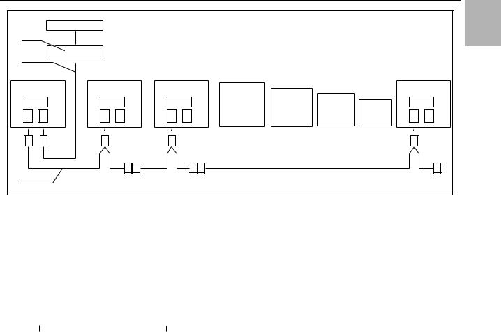
Fig. 21: Connection example: Master-slave operation
Key |
|
|
|
|
|
|
|
|
|
|
|
|
|
|
|
|
|
|
|
|
|
|
|
|
|
|
|
|
|
|
|
|
|
|
|
|
|
|
|
|
|
|
|
|
|
|
X2 Master/slave connection Sub-D, 9-pole |
|
|||||||||||||||||||||||||||||||||||||||||||||
1 |
|
Serial interface (Model No. 3124.200) |
|
|
|
|
|
|
|
|
|
|
|
|
|
|
|
X3 Serial interface Sub-D, 9-pole |
|
||||||||||||||||||||||||||||||||||||||||||||||||||||||||||||||||||||||||||
2 |
|
Serial interface cable |
|
|
|
|
|
|
|
|
|
|
|
|
|
|
|
St. |
|
Sub-D connector, 9-pole |
|
|
|
|
|
|
|
|
|
|
|
|
|
|
|
|
|
|
|
||||||||||||||||||||||||||||||||||||||||||||||||||||||
3 |
|
Master-slave bus cable (Model No. 3124.100) |
|
|
|
|
|
|
|
|
Bu. |
|
Sub-D jack, 9-pole |
|
|
|
|
|
|
|
|
|
|
|
|
|
|
|
|
|
|
|
|
|
|||||||||||||||||||||||||||||||||||||||||||||||||||||||||||
RTT |
Rittal TopTherm cooling units |
|
|
|
|
|
|
|
|
|
|
|
|
|
|
|
Adr. |
|
Address |
|
|
|
|
|
|
|
|
|
|
|
|
|
|
|
|
|
|
|
|
|
|||||||||||||||||||||||||||||||||||||||||||||||||||||
X1 Supply connection/door limit switch/alarms |
|
|
|
|
|
|
|
|
|
|
|
|
|
|
|
|
|
|
|
|
|
|
|
|
|
|
|
|
|
|
|
|
|
|
|
|
|
|
|
|
|
|
|
|
|
|
|
|
|
|
|
|
|
|
|||||||||||||||||||||||||||||||||||||||
|
|
|
|
|
|
|
|
|
|
|
|
|
|
|
|
|
|
|
|
|
|
|
|
|
|
|
|
|
|
|
|
|
|
|
|
|
|
|
|
|
|
|
|
|
|
|
|
|
|
|
|
|
|
|
|
|
|
|
|
|
|
|
|
|
|
|
|
|
|
|
|
|
|
|
|
|
|
|
|
|
|
|
|
|
|
|
|
|
|
||||
|
|
|
|
|
|
|
|
|
|
|
|
|
|
|
|
|
|
|
|
|
|
|
|
|
|
|
|
|
|
|
|
|
|
|
|
|
|
|
|
|
|
|
|
|
|
|
|
|
|
|
|
|
|
|
|
|
|
|
|
|
|
|
|
|
|
|
|
|
|
|
|
|
|
|
|
|
|
|
|
|
|
|
|
|
|
|
|
|
|
|
|
|
|
|
|
|
|
|
X2 |
|
|
|
|
|
|
|
|
|
|
|
|
|
|
|
|
|
X2 |
|
|
|
|
|
|
|
|
|
X2 |
|
|
|
|
|
|
|
|
|
|
|
|
X2 |
|
|
|
|
|
|
|
|
|
|
|
|
X2 |
|
|
|
|
|
|
|
|
|
|
|
|
|
|
|
|
|
X2 |
|
|
|
|
|
|
|
|
|
|
|
|||||
|
|
|
|
Adr.: 06 |
|
|
|
|
|
|
|
|
|
Adr.: 11 |
|
|
|
Adr.: 12 |
|
|
|
|
|
|
|
Adr.: 13 |
|
|
|
Adr.: 14 |
|
|
|
|
|
|
|
|
Adr.: 15 |
|
|
|
|
|
|
||||||||||||||||||||||||||||||||||||||||||||||||
|
|
|
1 |
|
|
|
|
|
|
|
|
|
|
2 |
|
|
|
|
|
|
|
2 |
|
|
|
|
|
|
|
|
2 |
|
|
|
|
|
|
|
|
2 |
|
|
|
|
|
|
|
|
|
|
2 |
|
|
|
|
|
|
|
|
|
|
||||||||||||||||||||||||||||||||
|
|
|
|
|
|
|
|
|
|
|
|
|
|
|
|
|
|
|
|
|
|
|
|
|
|
|
|
|
|
|
|
|
|
|
|
|
|
|
|
|
|
|
|
|
|
|
|
|
|
|
|
|
|
|
|
|
|
|
|
|
|
|
|
|
|
|
|
|
|
|
|
|
|
|
|
|
|
|
|
|
|
|
|
|
|
|
|
|
|
|
|
||
|
|
X10 |
L1 |
L2N |
PE |
1 |
2 |
3 |
4 |
5 |
|
X10 |
L1 |
L2 |
L3 |
PE |
1 |
2 |
3 |
4 |
5 |
X10 |
L1 |
L2N |
|
PE |
1 |
2 |
3 |
4 |
5 |
X10 |
L1 |
L2 |
L3 |
PE |
1 |
2 |
3 |
4 |
5 |
X10 |
L1 |
L2 |
L3 |
PE |
1 |
2 |
3 |
4 |
5 |
X10 |
L1 |
L2 |
L3 |
PE |
1 |
2 |
3 |
4 |
5 |
|
|
X2 |
|
|
|||||||||||||||||||||||||||
|
|
|
|
|
|
|
|
|
|
|
|
|
|
|
|
|
|
|
|
|
|
|
|
|
|
|
|
|
|
|
|
|
|
|
|
|
|
|
|
|
|
|
|
|
|
|
|
|
|
|
|
|
|
|
|
|
|
|
|
|
|
|
|
|
|
|
|
|
|
|
|
|
|
|
|
|
|
|
|
|
|
|
|
|
|
|
|
|
|
|
|
||
|
|
|
|
|
|
|
|
|
|
|
|
|
|
|
|
|
|
|
|
|
|
|
|
|
|
|
|
|
|
|
|
|
|
|
|
|
|
|
|
|
|
|
|
|
|
|
|
|
|
|
|
|
|
|
|
|
|
|
|
|
|
|
|
|
|
|
|
|
|
|
|
|
|
|
|
|
|
|
|
|
|
|
|
|
|
|
|
|
|
X10 |
|
||
|
|
|
|
|
|
|
|
|
|
|
|
|
|
|
|
|
|
|
|
|
|
|
|
|
|
|
|
|
|
|
|
|
|
|
|
|
|
|
|
|
|
|
|
|
|
|
|
|
|
|
|
|
|
|
|
|
|
|
|
|
|
|
|
|
|
|
|
|
|
|
|
|
|
|
|
|
|
|
|
|
|
|
|
|
|
|
|
|
|
5 |
|
|
|
|
|
|
|
|
|
|
|
|
|
|
|
|
|
|
|
|
|
|
|
|
|
|
|
|
|
|
|
|
|
|
|
|
|
|
|
|
|
|
|
|
|
|
|
|
|
|
|
|
|
|
|
|
|
|
|
|
|
|
|
|
|
|
|
|
|
|
|
|
|
|
|
|
|
|
|
|
|
|
|
|
|
|
|
|
|
|
|
|
|
|
|
|
|
|
|
|
|
|
|
|
|
|
|
|
|
|
|
|
|
|
|
|
|
|
|
|
|
|
|
|
|
|
|
|
|
|
|
|
|
|
|
|
|
|
|
|
|
|
|
|
|
|
|
|
|
|
|
|
|
|
|
|
|
|
|
|
|
|
|
|
|
|
|
|
|
|
|
|
|
|
|
|
|
|
|
|
|
|
|
|
|
|
|
4 |
|
|
|
|
|
|
|
|
|
|
|
|
|
|
|
|
|
|
|
|
|
|
|
|
|
|
|
|
|
|
|
|
|
|
|
|
|
|
|
|
|
|
|
|
|
|
|
|
|
|
|
|
|
|
|
|
|
|
|
|
|
|
|
|
|
|
|
|
|
|
|
|
|
|
|
|
|
|
|
|
|
|
|
|
|
|
|
|
|
|
|
|
|
|
|
|
|
|
|
|
|
|
|
|
|
|
|
|
|
|
|
|
|
|
|
|
|
|
|
|
|
|
|
|
|
|
|
|
|
|
|
|
|
|
|
|
|
|
|
|
|
|
|
|
|
|
|
|
|
|
|
|
|
|
|
|
|
|
|
|
|
|
|
|
|
|
|
|
|
|
|
|
|
|
|
|
|
|
|
|
|
|
|
|
|
|
|
3 |
|
|
|
|
|
|
|
|
|
|
|
|
|
|
|
|
|
|
|
|
|
|
|
|
|
|
|
|
|
|
|
|
|
|
|
|
|
|
|
|
|
|
|
|
|
|
|
|
|
|
|
|
|
|
|
|
|
|
|
|
|
|
|
|
|
|
|
|
|
|
|
|
|
|
|
|
|
|
|
|
|
|
|
|
|
|
|
|
|
|
|
|
|
|
|
|
|
|
|
|
|
|
|
|
|
|
|
|
|
|
|
|
|
|
|
|
|
|
|
|
|
|
|
|
|
|
|
|
|
|
|
|
|
|
|
|
|
|
|
|
|
|
|
|
|
|
|
|
|
|
|
|
|
|
|
|
|
|
|
|
|
|
|
|
|
|
|
|
|
|
|
|
|
|
|
|
|
|
|
|
|
|
|
|
|
|
|
2 |
|
|
|
|
|
|
|
|
|
|
|
|
|
|
|
|
|
|
|
|
|
|
|
|
|
|
|
|
|
|
|
|
|
|
|
|
|
|
|
|
|
|
|
|
|
|
|
|
|
|
|
|
|
|
|
|
|
|
|
|
|
|
|
|
|
|
|
|
|
|
|
|
|
|
|
|
|
|
|
|
|
|
|
|
|
|
|
|
|
|
|
|
|
1 |
|
|
|
|
|
|
|
|
|
|
|
|
|
|
|
|
|
|
|
|
|
|
|
|
|
|
|
|
|
|
|
|
|
|
|
|
|
|
|
|
|
|
|
|
|
|
|
|
|
|
|
|
|
|
|
|
|
|
|
|
|
|
|
|
|
|
|
|
|
|
|
|
|
|
|
|
|
|
|
|
|
|
|
|
|
|
|
|
|
|
|
|
|
|
|
|
|
|
|
|
|
|
|
|
|
|
|
|
|
|
|
|
|
|
|
|
|
|
|
|
|
|
|
|
|
|
|
|
|
|
|
|
|
|
|
|
|
|
|
|
|
|
|
|
|
|
|
|
|
|
|
|
|
|
|
|
|
|
|
|
|
|
|
|
|
|
|
|
|
|
|
|
|
|
|
|
|
|
|
|
|
|
|
|
|
|
|
PE |
|
|
|
|
|
|
|
|
|
|
|
|
|
|
|
|
|
|
|
|
|
|
|
|
|
|
|
|
|
|
|
|
|
|
|
|
|
|
|
|
|
|
|
|
|
|
|
|
|
|
|
|
|
|
|
|
|
|
|
|
|
|
|
|
|
|
|
|
|
|
|
|
|
|
|
|
|
|
|
|
|
|
|
|
|
|
|
|
|
|
|
|
|
|
|
|
|
|
|
|
|
|
|
|
|
|
|
|
|
|
|
|
|
|
|
|
|
|
|
|
|
|
|
|
|
|
|
|
|
|
|
|
|
|
|
|
|
|
|
|
|
|
|
|
|
|
|
|
|
|
|
|
|
|
|
|
|
|
|
|
|
|
|
|
|
|
|
|
|
|
|
|
|
|
|
|
|
|
|
|
|
|
|
|
|
|
|
L2N |
|
|
|
|
|
|
|
|
|
|
|
|
|
|
|
|
|
|
|
|
|
|
|
|
|
|
|
|
|
|
|
|
|
|
|
|
|
|
|
|
|
|
|
|
|
|
|
|
|
|
|
|
|
|
|
|
|
|
|
|
|
|
|
|
|
|
|
|
|
|
|
|
|
|
|
|
|
|
|
|
|
|
|
|
|
|
|
|
|
|
|
|
|
L1 |
|
|
|
|
|
|
|
|
|
|
|
|
|
|
|
|
|
|
|
|
|
|
|
|
|
|
|
|
|
|
|
|
|
|
|
|
|
|
|
|
|
|
|
|
|
|
|
|
|
|
|
|
|
|
|
|
|
|
|
|
|
|
|
|
|
|
|
|
|
|
|
|
|
|
|
|
|
|
|
|
|
|
|
|
|
|
|
|
|
|
|
|
Adr.: 16 |
|
|||
|
|
|
|
|
|
|
|
|
|
|
|
|
|
|
|
|
|
|
|
|
|
|
|
|
|
|
|
|
|
|
|
|
|
|
|
|
|
|
|
|
|
|
|
|
|
|
|
|
|
|
|
|
|
|
|
|
|
|
|
|
|
|
|
|
|
|
|
|
|
|
|
|
|
|
|
|
|
|
|
|
|
|
|
|
|
|
|
|
|
||||
|
|
|
|
|
|
|
|
|
|
|
|
|
|
|
|
|
|
|
|
|
|
|
|
|
|
|
|
|
|
|
|
|
|
|
|
|
|
|
|
|
|
|
|
|
|
|
|
|
|
|
|
|
|
|
|
|
|
|
|
|
|
|
|
|
|
|
|
|
|
|
|
|
|
|
|
|
|
|
|
|
|
|
|
|
|
|
|
|
|||||
|
|
|
|
|
|
|
|
|
|
|
|
|
|
|
|
|
|
|
|
|
|
|
|
|
|
|
|
|
|
|
|
|
|
|
|
|
|
|
|
|
|
|
|
|
|
|
|
|
|
|
|
|
|
|
|
|
|
|
|
|
|
|
|
|
|
|
|
|
|
|
|
|
|
|
|
|
|
|
|
|
|
|
|
|
|
|
|
|
|
|
|
|
|
|
|
|
|
|
|
|
|
|
|
|
|
|
|
|
|
|
|
|
|
|
|
|
|
|
|
|
|
|
|
|
|
|
|
|
|
|
|
|
|
|
|
|
|
|
|
|
|
|
|
|
|
|
|
|
|
|
|
|
|
|
|
|
|
|
|
|
|
|
|
|
|
|
|
|
|
|
|
|
|
|
|
|
|
|
|
|
|
|
|
|
|
|
|
|
|
|
|
|
|
|
|
|
|
|
|
|
|
1 |
|
2 |
|
|
|
|
|
|
|
|
|
|
|
|
|
|
|
|
|
|
|
|
|
|
3 |
|
|
|
|
|
|
|
|
|
|
|
|
4 |
|
|
|
|
|
|
|
|
|
|
|
|
|
5 |
|
6 |
|
|
|
|
|
|
|
|
|
|
|
|
|
|
|
|
|
|
|
||||||
|
|
|
|
|
|
|
|
|
|
|
|
|
|
|
|
3 |
|
|
|
|
|
|
|
|
|
|
|
|
|
|
|
4 |
|
|
4 |
|
|
|
|
|
|
|
|
|
|
|
|
|
|
|
|
|
|
|
|
|
3 |
2 |
|
||||||||||||||||||||||||||||||||||
|
|
|
|
|
|
|
|
|
|
|
|
|
|
|
|
|
|
|
|
|
|
|
|
|
|
|
|
|
|
|
|
|
|
|
|
|
|
|
|
||||||||||||||||||||||||||||||||||||||||||||||||||||||
Fig. 22: |
|
Connection example: Door limit switch and master-slave operation |
|
|
|
|
|
|
|
|
|
|
|
|
|
|
|
|
|
|
|
|
|
|
|
|
|
|
|
|
|
|
|
|
|
|
|
|
|||||||||||||||||||||||||||||||||||||||||||||||||||||||
Key
1 Master cooling unit
2Slave cooling units
3 2-door enclosure with two door limit switches
4Enclosure with door limit switch
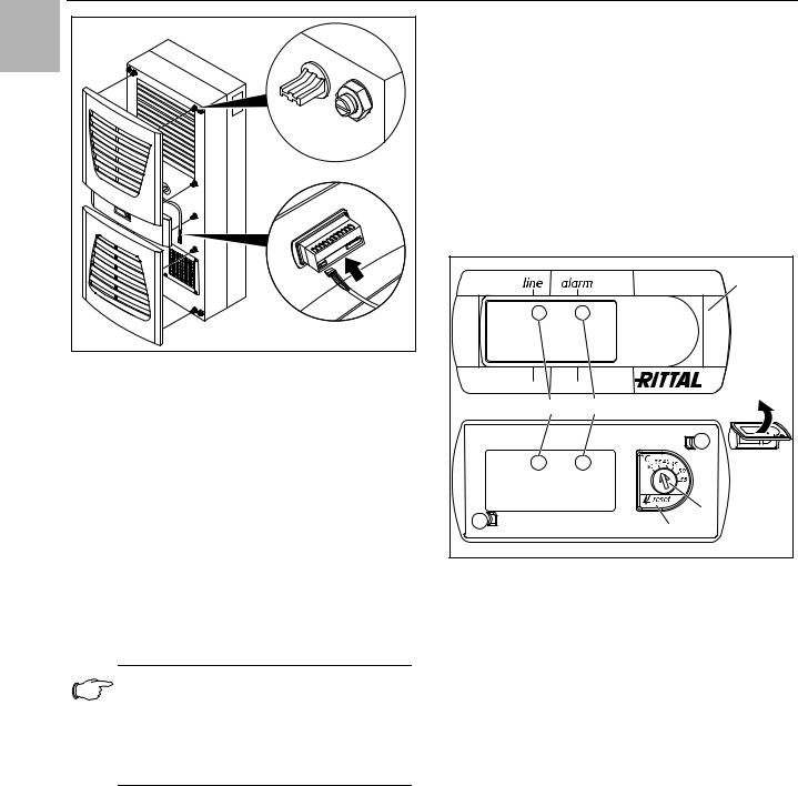
4.6.4Installing the power supply
Complete the electrical installation by following the wiring plan on the rear of the cooling unit (see fig. 2, for key see page 15).
If you would like the system messages from the cooling unit to be evaluated via the system message relay, you should also connect a suitable low-voltage cable to terminals 3 – 5.
Rittal enclosure cooling unit |
13 |
4 Assembly and connection
EN |
3302.100/.110, 3302.300/.310 |
|
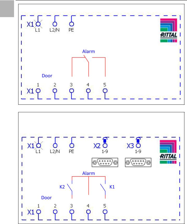
Fig. 23: Electrical wiring plan no. 1
3303.500/.510, 3303.600/.610, 3361.500/.510, 3361.600/.610, 3361.540/.640 3304.500/.510/.504/.514/.520/.600/.610 3305.500/.510/.504/.514/.520, 3328.500/.510/.504/.514/.520, 3329.500/.510/.504/.514/.520, 3305.600/.610, 3328.600/.610, 3329.600/.610, 3366.500/.510/.600/.610
Fig. 24: Electrical wiring plan no. 2
14 |
Rittal enclosure cooling unit |

4 Assembly and connection
|
|
|
|
|
|
3304.540/.544, 3305.540/.544, 3328.504/.544, 3329.504/.544 |
|
|
EN |
|
3304.640, 3305.640, 3328.640, 3329.640, 3366.540/.640, 3332.540/.640 |
|
|
|
|
|
|
|
|
|
|
|
|
|
|
|
|
|
|
Fig. 25: Electrical wiring plan no. 3
Key
X1 Main terminal strip
X2 Master/slave connection
X3 Optional interface
K1 Relay collective fault 1
K2 Relay collective fault 2
Door Door limit switch (without door limit switch: terminal 1, 2 open)
Note:
For technical data, refer to the rating plate.
textile plants with heavy lint contamination, lint screens should be used (available as an optional extra).
Pull the louvred air inlet grille off the enclosure.
Insert the filter mat into the louvred grille as shown in fig. 26 and push it back onto the enclosure.
AC |
DC |
cos φ = 1 |
Res. Load |
|
|
I max. = 2 A |
I min. = 100 mA |
U max. = 250 V |
U max. = 30 V |
|
I max. = 2 A |
|
|
Tab. 2: Relay contact data |
|
4.7Finalising assembly
4.7.1Installing the filter media
The entire cooling unit condenser is covered with a dirtrepelling, easy-to-clean RiNano coating. In many applications, therefore, the use of filter media is unnecessary, particularly with dry dusts.
For dry, coarse dust and lint in the ambient air, we recommend installing an additional PU foam filter mat (available as an accessory) in the cooling unit. For air containing oil condensate, we recommend the use of metal filters (also available as an accessory). When used in
Fig. 26: Installing the filter mat
4.7.2Fitting the cooling unit
For partial and full internal mounting only.
Connect the connector to the rear of the display.
Place the louvred grille onto the unit at the front, and press it down until you hear it snap into place.
Rittal enclosure cooling unit |
15 |
5 Start-up
EN |
Fig. 27: Connect the display and attach the louvred grille
4.7.3Setting the filter mat monitor (only with e-Comfort controller)
Function of the filter mat monitor:
Dirt on the filter mat is automatically detected by measuring the temperature difference in the external circuit of the cooling unit (see section 6.2.6 "Programming overview"). As the level of filter mat soiling increases, the temperature difference will increase. The setpoint value of the temperature difference in the external circuit adapts automatically to the relevant operating points in the performance diagrams. Hence there is no need to readjust the setpoint value for different unit operating points.
5Start-up
Note:
The oil must be collected in the compressor in order to ensure effective lubrication and cooling.
Do not operate the cooling unit for at least 30 minutes after assembling the equipment.
Once all the assembly and installation work is complete, switch on the power supply to the cooling unit.
The cooling unit starts running:
–With Basic controller: The green operating LED ("line") is illuminated.
–With e-Comfort controller: The software version of the controller first appears for approx. 2 seconds, then "ECO" to show Eco mode is enabled. The internal enclosure temperature will then appear in the 7-segment display
You can now make your individual settings on the unit, e.g. set the temperature or (with e-Comfort controller only) assign the network identifier, etc. (refer to section 6 "Operation").
6Operation
You can operate the cooling unit using the controller on the front of the device (fig. 2, item 11). Depending on the model, the unit is equipped with a Basic or e-Comfort controller.
6.1 Control using the Basic controller
For Model Nos. 3302.xxx.
|
1 |
3 |
4 |
|
2 |
|
5 |
Fig. 28: Basic controller
Key
1 Controller trim panel
2 Temperature setter
3 LED green ("line")
4 LED red ("alarm")
5Reset button
6.1.1Properties
–Rated operating voltage: 115 V or 230 V
–Integral start-up delay and door limit switch function
–Protective function to prevent icing
–Monitoring of all motors (compressor, condenser fan, evaporator fan)
–Phase monitoring for three-phase units
–Visualisation of the operating status via LED display:
–Voltage on, unit operational
–Door open (only if door limit switch installed)
–Warning of overtemperature
–High-pressure monitor has switched
–Switching hysteresis: 5 K
If the cooling unit and compressor run times are too long < 1 minute, the switching hysteresis to protect the cooling unit is automatically increased.
–Floating system message contact in case of overtemperature
16 |
Rittal enclosure cooling unit |

6 Operation
–Temperature setting
(setting range 30 – 55°C) via potentiometer
–Test function
–Flashing mode to indicate system messages. See section 6.1.2 "Operating and error display"
The cooling unit operates automatically, i.e. after switching on the power supply, the evaporator fan (see fig. 3) will run continuously and permanently circulate the inter-
nal enclosure air. The built-in Basic controller ensures automatic normal shut-down operation of the cooling EN unit by the value of the fixed preset switching difference
of 5 K.
6.1.2Operating and error display
The Basic controller monitors and controls the cooling unit. It indicates the operating and error status via the green and red LEDs (fig. 28, items 3 and 4):
LED |
|
Status |
Cause |
|
|
Solution |
|
|
|
|
|
|
|
Green |
|
Illuminated |
Power supply on, |
|
|
– |
(line) |
|
|
unit operational |
|
|
|
|
|
|
|
|
|
|
|
|
Flashing |
Only with door limit switch installed: |
|
In order to avoid condensation, close the enclo- |
|
|
|
|
enclosure door open |
|
|
sure door as quickly as possible. |
|
|
|
|
|
|
|
|
|
|
Only with door limit switch installed: |
|
Check the position of the door limit switch. |
|
|
|
|
enclosure door closed |
|
|
|
|
|
|
|
|
|
|
Red |
|
Alarm/error/warning |
Number of flash |
Flash interval |
||
(alarm) |
|
|
intervals for the |
|
||
|
|
|
|
red LED |
|
|
|
|
|
|
|
|
|
|
|
Implement a |
Device reset |
(12) |
|
|_|_|_|_|_|_|_|_|_|_|_|*****|_|_|_|_|_|_|_|_|_|_|_| |
|
|
reset |
|
|
|
|
|
|
High pressure alarm |
(0) |
|
|_|_|_|_|_|_|_|_|_|_|_|_|_|_|_|_|_|_|_|_|_|_|_|_|_| |
|
|
|
|
|
|||
|
|
|
|
|
|
|
|
|
Sensors |
Potentiometer defective or |
(3) |
|
|_|_|*****|_|_|*****|_|_|*****|_|_|*****|_|_|***** |
|
|
|
display error |
|
|
|
|
|
|
|
|
|
|
|
|
|
Internal temperature |
(4) |
|
|_|_|_|*****|_|_|_|*****|_|_|_|*****|_|_|_|***** |
|
|
|
sensor defective |
|
|
|
|
|
|
|
|
|
|
|
|
|
Anti-icing sensor defective |
(5) |
|
|_|_|_|_|*****|_|_|_|_|*****|_|_|_|_|*****|_|_|_|_| |
|
|
|
|
|
|
|
|
|
Overload |
Compressor overloaded |
(6) |
|
|_|_|_|_|_|*****|_|_|_|_|_|*****|_|_|_|_|_|***** |
|
|
|
|
|
|
|
|
|
|
Interior fan overloaded |
(7) |
|
|_|_|_|_|_|_|*****|_|_|_|_|_|_|*****|_|_|_|_|_|_| |
|
|
|
|
|
|
|
|
|
|
Exterior fan overloaded |
(8) |
|
|_|_|_|_|_|_|_|*****|_|_|_|_|_|_|_|***** |
|
|
|
|
|
|
|
|
|
Device sta- |
Overload mode |
(9) |
|
|_|_|_|_|_|_|_|_|*****|_|_|_|_|_|_|_|_|***** |
|
|
tus/state |
(heat loss) |
|
|
|
|
|
|
|
|
|
|
|
|
Warning |
Anti-icing alarm |
(2) |
|
|_|*****|_|*****|_|*****|_|*****|_|*****|_|*****|_| |
|
|
|
|
|
|
|
|
|
|
Overtemperature warning |
(1) |
|
|*****|*****|*****|*****|*****|*****|*****|*****|*****| |
|
|
|
|
|
|
|
Off |
|
No display |
No power |
– |
|
Check power supply |
|
|
|
|
|
|
|
|
|
|
Rotary current phase moni- |
– |
|
Swap phases |
|
|
|
toring: |
|
|
|
|
|
|
"LED off" = Incorrect |
|
|
|
|
|
|
phase connection |
|
|
|
|
|
|
|
|
|
|
Tab. 3: Operating and error display on the Basic controller |
|
|
|
|||
Key to flash intervals |
|
|
nection diagrams under section 4.6.4 "Installing the |
|||
| |
= |
500 ms (red LED on) |
|
power supply"): |
||
_ |
= |
500 ms (red LED off) |
|
– Terminal 3: NC (normally closed) |
||
***** |
= |
3 s pause (red LED off) |
|
– Terminal 4: C (connection of the supply voltage to the |
||
|
|
|
|
|
||
The overtemperature message may also be polled via an |
fault signal relay) |
|||||
– Terminal 5: NO (normally open) |
||||||
integral floating contact on the cooling unit terminal (sys- |
The NC and NO definitions refer to the de-energised |
|||||
|
|
|
|
|
||
tem message relay with changeover contact, see con- |
state. As soon as power is applied to the cooling unit, |
|
Rittal enclosure cooling unit |
17 |

6 Operation
the system message relay picks up, so that the relay EN contacts change status (contact 3 – 4 open; contact 4 –
5 closed).
This is the normal operating state of the cooling unit. As soon as an error message occurs or the power supply is interrupted, the relay drops out and contact 3 – 4 is closed.
6.1.3 Test mode with the Basic controller
The Basic controller is equipped with a test function whereby the cooling unit commences cooling operation independently of the set temperature or door limit switch function.
First you must remove the controller trim panel.
Switch off the mains voltage.
Remove the louvred grille or infill panel in which the controller is installed.
Release the display lock from behind and pull it forwards slightly.
Fig. 29: Releasing the Basic controller trim panel
Carefully lift the trim panel, e.g. using your thumb or a flat screwdriver, and remove it.
You can now start test mode.
Rotate the potentiometer to the left-hand stop, then hold the rubberised potentiometer display down while you re-connect the mains voltage.
The cooling unit will commence operation and the green LED will flash (I_II_I_II_ . . .). Test mode is completed after approximately 5 minutes. The unit switches off and changes to normal operation.
Key
I= LED 500 ms on
_= LED 500 ms off
In normal operation, the green LED is permanently illuminated.
Next, rotate the potentiometer back to the required setpoint.
6.1.4Setting the temperature
Note:
With the Basic controller, the temperature is preset at the factory to +35°C.
In order to save energy, do not set the temperature lower than that actually necessary.
To change the temperature setting:
Take the trim panel off the controller as described in section 6.1.3 "Test mode with the Basic controller".
Set the required temperature on the temperature setting device (fig. 28).
Carefully push the trim panel onto the display until you hear it snap into place.
Push the display back into the infill panel or louvred grille.
Re-attach the louvred grille or infill panel to the cooling unit.
6.1.5Resetting the Basic controller
Following a high-pressure alarm in the cooling cycle, and once the cause has been rectified, you will need to manually reset the Basic controller:
Take the trim panel off the Basic controller as described in section 6.1.3 "Test mode with the Basic controller".
Press the reset button (fig. 28, item 5) for at least 3 seconds.
The red LED is extinguished.
Re-install the Basic controller.
6.2 Control using the e-Comfort controller
For unit types 33xx.5xx and 33xx.6xx.
1 |
2 |
4 |
3 |
Fig. 30: e-Comfort controller
Key
1Programming button, also display of the set temperature unit (degrees Celsius)
2Set button
3Programming button, also display of the set temperature unit (degrees Fahrenheit)
47-segment display
18 |
Rittal enclosure cooling unit |
Loading...