

Page 1
Conversion Manual for Tankless Water Heaters
WARNING
This conversion kit shall be installed by a qualified
service agency in accordance with the
manufacturer’s instructions and all applicable
codes and requirements of the authority having
jurisdiction. The information in these instructions
must be followed to minimize the risk of fire or
explosion or to prevent property damage, personal
injury or death. The qualified service agency is
responsible for the proper installation of this kit.
The installation is not proper and complete until
the operation of the converted appliance is
checked as specified in the manufacturer’s
instructions supplied with the kit.
for the conversion from
Natural Gas (NG) to
Liquid Propane Gas (LPG)
for the conversion from
Liquid Propane Gas (LPG) to
Natural Gas (NG)
for adjustments at high altitude
(greater than 2000 ft / 610 m)
Refer to Adjust Gas Pressure Settings
V53De .............. REU-AM1620WD-US
This model is certified for installation in mobile homes.
Page 2
2 Rinnai Corporation Conversion Manual
Safety Symbols
Indicates an imminently hazardous situation which, if not avoided, will result in death or
serious injury.
Indicates a potentially hazardous situation which, if not avoided, could result in death or
serious injury.
Indicates a potentially hazardous situation which, if not avoided, could result in minor or
moderate injury. It may also be used to alert against unsafe practices.
This is the safety alert symbol. This symbol alerts you to potential hazards that can kill or hurt you and
others.
DANGER
CAUTION
WARNING
Technical Data ........................... 2-3
Parts List ....................................... 3
Gas Conversion Procedure ........... 4
Adjust Gas Pressure Settings ....... 5
Check Operation ........................... 6
Operating Instructions ................... 7
FOR INSTALLATIONS IN CANADA, THE CONVERSION SHALL BE CARRIED OUT IN ACCORDANCE WITH
THE REQUIREMENTS OF THE PROVINCIAL AUTHORITIES HAVING JURISDICTION AND IN ACCORDANCE
WITH THE REQUIREMENTS OF THE CGA-B149.1, NATURAL GAS AND PROPANE INSTALLATION CODE.
The appliance must be installed in accordance with:
• local codes or, in the absence of local codes, the National Fuel Gas Code, ANSI Z223.1/
NFPA 54 and/or CSA B149.1, Natural Gas and Propane Installation Code.
• the Manufactured Home Construction and Safety Standard, Title 24 CFR, Part 3280 and/or
CAN/CSA Z240 MH Series, Mobile Homes, Series M86.
Natural Gas (Gaz Naturel)
Minimum - Maximum supply gas pressure
(Pression de gaz d'alimentation - Minimum - Maximum)
MIN 4.5 in (114 mm) W.C.
MAX 10.5 in (267 mm) W.C.
Propane Gas (Gaz propane)
Minimum - Maximum supply gas pressure
(Pression de gaz d'alimentation - Minimum - Maximum)
MIN 8 in (203 mm) W.C.
MAX 13.5 in (343 mm) W.C.
Technical Data (Données Techniques)
Page 3
Rinnai Corporation Conversion Manual 3
The input rate can be verified by following the procedure in the National Fuel Gas Code (NFPA54 / ANSI Z223.1,
2006 or latest edition).
Le taux d'entrée peut être vérifié en suivant la procédure décrite dans le code national de gaz combustible
(NFPA54 / Z223.1 ANSI, 2006 ou plus récente édition).
Technical Data (Données Techniques)
Model (Modèle) V53De
Minimum Gas Consumption Btu/h
(BTU/heure consummation - Minimum)
15,500
Maximum Gas Consumption Btu/h
(BTU/heure consummation - Maximum)
120,000
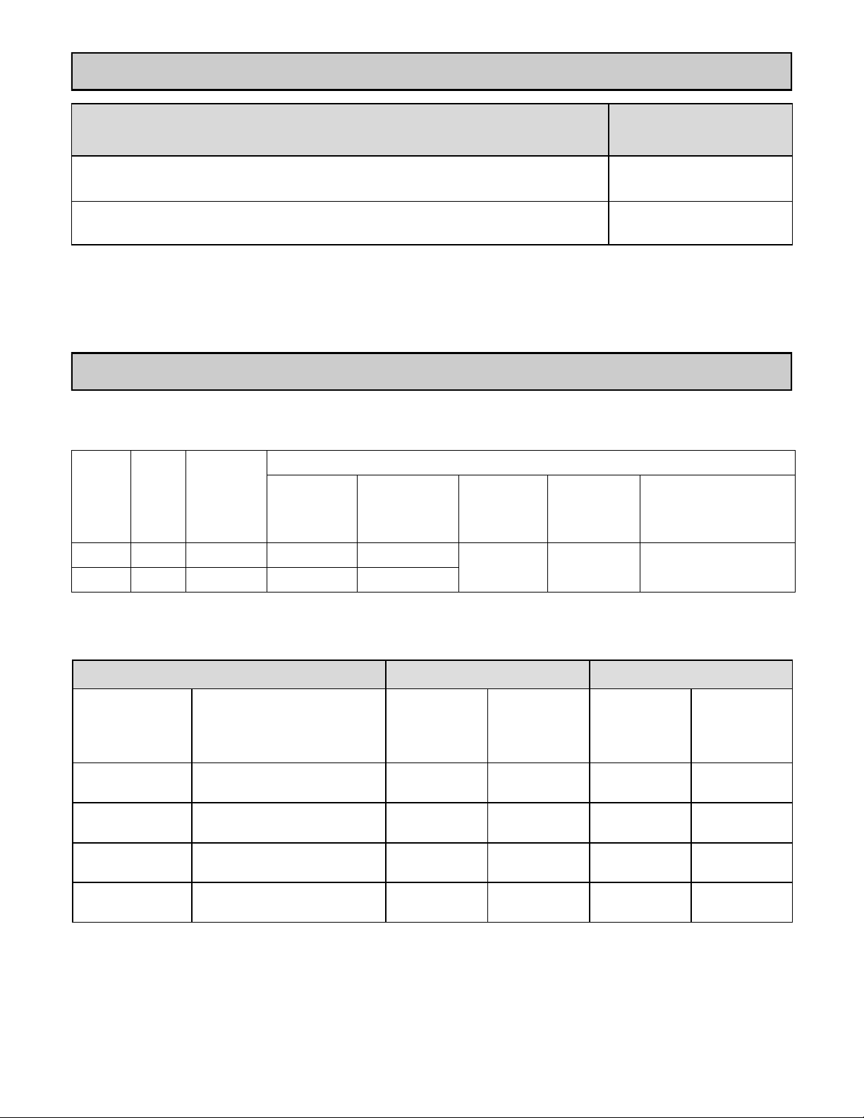
Parts List (Liste des Pièces)
The gas manifold is stamped either “LPG” for liquid propane gas or “NG” for natural gas.
(Le collecteur de gaz est estampillé soit de "LPG" pour le gaz propane liquide ou de "NG" pour le gaz naturel.)
Model
(Modèle)
To Gas
type
(au gaz)
Kit Number
(Numero de
kit)
Kit Contents (Contenu de kit)
Conversion
Rating Plate
(Plaque de
Conversion)
Gas Manifold
(Gaz collecteur)
Damper
(Amortisseur)
Instruction
Label
(Étiquette
d'instruction)
Conversion Manual
(Manuel de conversion)
V53De LPG 103000092 100000568 106000144
100000569 100000566 106000146
V53De NG 103000093 100000567 106000145
V53De (REU-AM1620WD-US)
Natural Gas (Gaz Naturel) Propane Gas (Gaz propane)
Dip Switch
Settings
(commutateur
position)
Altitude
Max Rate
(rythme max)
inches W.C.
(mm W.C.)
Min Rate
(rythme min)
inches W.C.
(mm W.C.)
Max Rate
(rythme max)
inches W.C.
(mm W.C.)
Min Rate
(rythme min)
inches W.C.
(mm W.C.)
#2 OFF, #3 OFF 0-2000 ft (0-610 m) 3.90
(99.1)
0.63
(16.0)
4.70
(119.4)
0.79
(20.1)
#2 OFF, #3 ON 2001-5200 ft (610-1585 m) 3.68
(93.5)
0.70
(17.8)
3.75
(95.3)
0.71
(18.0)
#2 ON, #3 OFF 5201-7700 ft (1585-2347 m) 3.60
(91.4)
0.70
(17.8)
3.32
(84.3)
0.74
(18.8)
#2 ON, #3 ON 7701-10200 ft (2347-3109 m) 3.46
(87.9)
0.69
(17.5)
2.71
(68.8)
0.76
(19.3)
Page 4

4 Rinnai Corporation Conversion Manual
NOTICE
2 machine
screws
(gas valve)
Confirm that the inlet gas pressure is between the minimum and maximum pressures allowed for this appliance.
Gas Conversion Procedure
If subsequent conversions are made
then a new conversion label must be
placed on the water heater to
accurately reflect the gas type.
6 screws
(gas
manifold)
Figure 1
1. Disconnect the electrical power.
2. Turn off the gas supply and water.
3. Remove 4 screws securing the front panel. Remove
front panel.
NOTE: Set aside screws in Steps 3-6 separately.
4. Remove the 6 screws that attach the gas manifold
to the burner case on the heat exchanger assembly.
See Figure 1.
5. Remove the display mounting screw and the ignitor unit
screw to replace the gas manifold. See Figure 1.
6. Remove the 2 screws that attach the gas manifold
to the gas valve. These screws are machine screws
and must be used at these locations.
7. Disconnect electrode and flame rod wires and remove
the gas manifold.
8. Make sure that the black O-Ring is intact on the gas
control valve (see Figure 2) and the gasket is intact on
the replacement gas manifold. Position the new gas
type manifold in place.
9. Install the gas manifold with the 2 machine screws
at the gas valve.
10. Install replacement gas manifold with 6 screws at
burner case on the heat exchanger assembly.
11. Install the ignitor module & bracket screw and the
status monitor screw.
12. Connect the electrode and flame rod wires.
13. Turn on the 120 V power supply.
14. Push and hold PB2 to enter MODE function. LED
displays 1, then changes to A or C.
15. Set the gas type value to the appropriate type A (LPG)
or C (NG). To do this, push PB4 until LED displays A
(LPG) or C (NG).
16. Press and hold PB2 to exit MODE function.
17. Complete the section, Adjust Gas Pressure Settings.
18. Complete the section, Check Operation.
19. Complete the data on the conversion rating plate and
place it on the left side of the unit to cover up the gas
pressures and gas label (on indoor models) for the
other gas type. Do not cover up the Recover Rating.
20. Place the instructions label on the top right side of the
unit.
1 ignitor module and
bracket screw and
1 status monitor screw
O-Ring
Figure 2
Electrode and flame rod wires
Page 5

Rinnai Corporation Conversion Manual 5
Adjust Gas Pressure Settings
1. Turn OFF the gas supply.
2. Remove the front panel (four screws).
3. Check the gas type using the new rating label on
the side of the unit.
4. Confirm gas type was selected correctly from the
Gas Conversion Procedure section (steps 14-16).
5. Turn OFF the power supply.
6. Remove the test port sealing screw and attach a
manometer to the burner test point located on the
gas control. Figure 1.
7. Turn on the gas supply and the power supply.
8. If a controller is installed, turn the unit ON and
select maximum delivery temperature.
9. Open all available hot water taps to flow water
through the water heater at the maximum flow rate
obtainable. (At least 3 gallons per minute is
recommended. If there is not enough water
flowing, the water heater could shut off or sustain
damage due to overheating.)
10. To set unit into “Forced Low”, press and hold PB5
until the LED display will show “L”. The front status
monitor will show “FL”. Figure 2
11. Calibrate to Forced Low using PB3 to increase
gas pressure and PB4 to decrease. Figure 2
12. To set unit into “Forced High”, press and hold PB5
until the LED display will show “H”. The front status
monitor will show “FH”. Figure 2
13. Calibrate to Forced High using PB3 to increase
gas pressure and PB4 to decrease. Figure 2
CAUTION
Do not touch the areas at or near the heat exchanger
or hot water lines. These areas become very hot and
could cause burns.
CAUTION
Do not touch any other areas on the PC board
besides the “SW” switches while power is supplied to
the appliance. Parts of the PC board are supplied
with 120 volts AC.
14. Use the Gas Pressure Settings on “Technical
Data” page of this manual for your model, gas
type, and altitude.
15. Return the unit to normal operation by pressing
and holding PB5 until the LED display turns off.
16. Close hot water taps.
17. Turn off both gas supply and 120 V power supply.
18. Remove manometer and install test port sealing
screw.
19. Turn on both the gas supply and 120 V power
supply.
20. Operate the unit and check for gas leaks.
21. Install the front panel using four screws.
Complete this section for high altitude installation or after converting for gas type.
Confirm that the inlet gas pressure is between the minimum and maximum pressures allowed for this appliance.
Figure 2
1. Push Buon 2 (PB2) - Black
MODE buon, places the PCB into
programming mode.
2. Push Buon 3 (PB3) - White
MENU buon, cycles through available
menus 1 - 6. Increases gas pressure during
forced mode operaon.
3. Push Buon 4 (PB4) - White
VALUE buon, cycles through available
menu values. Decreases gas pressure during forced mode operaon.
4. Push Buon 5 (PB5) - White
Forced High/Low selecon rate seng.
5. LED Digital Display
Displays MENU ( 1, 2, etc.), VALUE ( A, ,
etc.) and Forced Low/High status ( L
or H ).
6. Dipswitch
By factory default, all switches are in OFF
posion. Used for High Altude adjustment.
Figure 1
Burner test point
PB2
PB3
PB4
PB5
LED
Dip
Switch
Page 6

6 Rinnai Corporation Conversion Manual
Normal Operating Sequence
When pressing the ON/OFF button, the LED display
will illuminate, the combustion fan will begin to run if
water is flowing, and the sparker will ignite the main
burner.
This heater has an automatic ignition system. When
the main burner has lit, the combustion lamp will glow
red, and the spark will stop.
Check Operation
Visual Inspection of Flame
Check that the burner flames are operating normally.
The flame can be seen through the circular window
above the burner.
When operating normally the burner flame should burn
evenly over the entire surface. The flame should be
clear, blue, and stable. A yellow flame is abnormal and
maintenance is required.
Page 7

Rinnai Corporation Conversion Manual 7
Operating Instructions
FOR YOUR SAFETY READ BEFORE OPERATING
A. This appliance does not have a pilot. It is
equipped with an ignition device which
automatically lights the burner. Do not try to light
the burner by hand.
B. BEFORE OPERATING, smell all around the
appliance area for gas. Be sure to smell next to
the floor because some gas is heavier than air and
will settle on the floor.
WHAT TO DO IF YOU SMELL GAS:
• Do not try to light any appliance.
• Do not touch any electric switch; do not use any
phone in your building.
• Immediately call your gas supplier from a
neighbor’s phone. Follow the gas supplier’s
instructions.
• If you cannot reach your gas supplier, call the fire
department.
C. Use only your hand to push in or turn the gas
control knob. Never use tools. If the knob will not
push in or turn by hand, do not try to repair it, call a
qualified licensed professional. Force or attempted
repair may result in a fire or explosion.
D. Do not use this appliance if any part has been
under water. Immediately call a qualified licensed
professional to inspect the appliance and to
replace any part of the control system and any gas
control which has been under water.
(N’utilisez pas cet appareil s’il a été plongé dans
l’eau, même partiellement. Faites inspecter
l’appareil par un technicien qualifié et remplacez
toute partie du système de contrôle et toute
commande qui ont été plongés dans l’eau).
TO TURN OFF GAS TO APPLIANCE
1. Turn off all electric power to the appliance using
the ON/OFF button.
2. Set the thermostat to lowest setting.
3. Turn the gas valve clockwise to the full OFF
position.
OPERATING INSTRUCTIONS
If you do not follow these instructions exactly, a fire or explosion may
result causing property damage, personal injury or loss of life.
WARNING
1. STOP! Read the safety information above.
2. Set the thermostat to lowest setting.
3. Turn off electric power to the appliance using the
ON/OFF button.
4. This appliance is equipped with an ignition device
which automatically lights the burner. Do not try to
light the burner by hand.
5. Turn the gas valve clockwise to the full OFF
position
6. Wait five (5) minutes to clear out any gas. Then
smell for gas, including near the floor. If you smell
gas, STOP! Follow “B” in the safety information
above. If you don’t smell gas, go to the next step.
7. Turn the gas valve counterclockwise to the full ON
position.
8. Turn on electric power to the appliance using the
ON/OFF button.
9. Set the thermostat to desired setting.
10. Open a hot water tap. If the appliance will not
operate, follow the instructions “To Turn Off Gas
To Appliance” and call your licensed professional
or gas supplier. See manual for additional
information.
CLOSE
Manual Valve
OPEN
AVERTISSEMENT
Page 8

100000566(01)
7/2018
U340-1922
 Loading...