


Energysaver ®
Gas Direct Vent Wall Furnace
EX38C.................(RHFE-1005FTA)
Installer: Leave this manual with the appliance.
Consumer: Retain this manual for future reference.

 WARNING If the information in these instructions is not followed exactly, a fire or explosion may result causing property damage, personal injury or death.
—Do not store or use gasoline or other flammable vapors and liquids in the vicinity of this or any other appliance.
—WHAT TO DO IF YOU SMELL GAS
Do not try to light any appliance.
Do not touch any electrical switch; do not use any phone in your building.
Immediately call your gas supplier from a neighbor’s phone. Follow the gas supplier’s instructions.
If you cannot reach your gas supplier, call the fire department.
—Installation and service must be performed by a licensed professional.
READ ALL OF THE INSTRUCTIONS THOROUGHLY BEFORE INSTALLING OR OPERATING THIS HEATER.
This manual provides information on the installation, operation, and maintenance of the heater. For proper operation and safety, it is important to follow the instructions and adhere to the safety precautions.
A licensed professional must install the fan convection heater according to the exact instructions within this manual.
The consumer must read the entire manual to properly operate the heater and to have regular maintenance performed.
This appliance may be installed in an aftermarket, permanently located, manufactured (mobile) home, where not prohibited by local codes.
Register your product at www.rinnairegistration.com or call 1-866-RINNAI1 (746-6241)

This appliance may be installed as an OEM installation in a manufactured home (USA only) or mobile home and must be installed in accordance with the manufacturer’s instructions and the
Manufactured Home construction and Safety Standard, Title 24 CFR, Part 3280, in the United States, or the Mobile Home Standard, CAN/CSA Z240 MH Series, in Canada.
This appliance may be installed in an aftermarket, permanently located, manufactured home (USA only) or mobile home, where not prohibited by local codes.
This appliance is only for use with the type of gas indicated on the rating plate. This appliance is not convertible for use with other gases, unless a certified kit is used.
Table of Contents
Consumer Safety Information |
|
Safety Definitions ............................................. |
3 |
Safety Behaviors and Practices ....................... |
3 |
Safety Features................................................ |
4 |
Specifications |
|
Appliance Specifications .............................. |
4, 5 |
Features ........................................................... |
5 |
Flue Manifolds .................................................. |
5 |
Operating Instructions |
|
Getting to Know your New Heating Appliance 6 |
|
Control Panel ................................................... |
7 |
On / Off............................................................. |
7 |
Child Lock ........................................................ |
7 |
Setting the Clock .............................................. |
8 |
Operating the Heater Manually ........................ |
8 |
Setting and Operating the Timers .................... |
8 |
Override Function............................................. |
9 |
Economy (Energy Saving Mode) ..................... |
9 |
Set Back ......................................................... |
10 |
Humidifier and Air Flow Direction................... |
10 |
Care and Maintenance................................... |
11 |
Before Making a Service Call......................... |
12 |
Fault Codes .................................................... |
13 |
Restart Function ............................................. |
14 |
Troubleshooting ............................................. |
14 |
Installation Instructions |
|
General Instructions....................................... |
15 |
Gas Connection ............................................. |
16 |
Clearances to Combustibles.......................... |
16 |
Flue Terminal Clearances........................ |
17, 18 |
Dimensions .................................................... |
19 |
Installation Parts ........................................... |
20 |
Drilling Flue Hole ........................................... |
21 |
Attach Wall Brackets...................................... |
21 |
Attach Back Spacers ..................................... |
21 |
Flue Manifold Installation ......................... |
22, 23 |
Extension Kit Installation........................... |
24-26 |
Connecting the Appliance.............................. |
27 |
Adjust Gas Pressure Settings.................. |
28, 29 |
Operating Instructions.................................... |
30 |
Cut-Away Diagram......................................... |
31 |
Wiring Diagram .............................................. |
32 |
Ladder Diagram ............................................. |
33 |
Parts List ................................................... |
34-41 |
Consumer Support |
|
Warranty Information ..................................... |
42 |
Limited Warranty...................................... |
42, 43 |
State Regulations.............................................. |
44 |
2 |
Rinnai Corporation EX38C Manual |

Consumer Safety Information
Safety Definitions
This is the safety alert symbol. This symbol alerts you to potential hazards that can kill or hurt you and others.
 DANGER
 WARNING
 CAUTION
Indicates an imminently hazardous situation which, if not avoided, will result in death or serious injury.
Indicates a potentially hazardous situation which, if not avoided, could result in death or serious injury.
Indicates a potentially hazardous situation which, if not avoided, could result in minor or moderate injury. It may also be used to alert against unsafe practices.
Safety Behavior and Practices
 WARNING
Repairs should be performed by a qualified service technician.
Keep the area around the appliance clear and free from combustible materials, gasoline, and other flammable vapors and liquids.
Never store liquid propane containers indoors.
Do not use this appliance if any part has been under water. Immediately call a qualified service technician to inspect the appliance and to replace any part of the control system and any gas control which has been under water.
This appliance is equipped with a three-prong plug for your protection against shock hazard and should be plugged directly into a properly grounded threeprong receptacle. Do not cut or remove the ground prong from this plug.
Any alteration to the appliance or its controls can be dangerous.
Do not operate appliance with the panels removed, cracked or broken. Replacement of the panels should be done by a licensed or qualified service person.
 CAUTION
Do not block the warm air discharge. Do not allow anyone to sleep directly in front of the appliance.
Due to high temperatures, the appliance should be located out of traffic and away from furniture and draperies.
Children and adults should be alerted to the hazards of high surface temperature and should stay away to avoid burns or clothing ignition.
Young children should be carefully supervised when they are in the same room as the appliance.
Clothing or other flammable material should not be placed on or near the appliance.
Any safety screen or guard removed for servicing must be replaced prior to operating the appliance.
Do not insert items into the louvers.
Do not spray aerosols near the appliance while it is operating. Most aerosols contain butane gas which is flammable.
Do not unplug the appliance while it is operating or while the fans are on.
Do not use bare hands to touch the front louvers due to high temperatures which may cause burns.
Wear hand protection when touching the side back covers, front louver, and rear intake for the convection fan.
Prevent dust from accumulating on the power cord, side covers, and parts behind the appliance.
Do not sit on the heater.
Do not place containers of liquid on top of the heater. Water spillage can cause extensive damage to the appliance and may result in electric shock.
Rinnai Corporation EX38C Manual |
3 |

Safety Features
Overheat: The appliance will automatically shut down when the appliance exceeds a predetermined temperature.
Flame Failure: The appliance will automatically shut down if the burner flame is extinguished.
Power Failure: The appliance will cut off the gas if it loses electrical power.
Power Surge Fuse: A glass fuse on the PC board protects against overcurrent. If the fuse blows then all indicator lamps will be off.
Spark Detector: The appliance automatically shuts down if there is an abnormal spark at ignition.
Fusible Link: In case the overheat feature prevents the temperature from rising then the fusible link will break shutting off the appliance.
|
|
Specifications |
|
|
Appliance Specifications |
||
|
|
|
|
Application |
For manufactured home (USA only) or mobile home or residential installation |
||
|
|
convertible for use with natural gas and liquefied petroleum gases (propane / |
|
|
|
LPG) when provision is made for the simple conversion from one gas to the |
|
|
|
other. |
|
|
|
For commercial setting. |
|
|
|
For installation at altitudes up to 10,200 feet (3109 m). |
|
|
|
|
|
General Description |
Forced combustion, forced convection, flued gas furnace |
||
|
|
|
|
Operation |
Push button electronic |
||
|
|
|
|
Gas Connection |
1/2 in NPT |
||
|
|
|
|
Gas Control |
Electronic |
||
|
|
|
|
Burners |
Stainless steel Bunsen burner |
||
|
|
|
|
Temperature Control |
Electronic thermostat |
||
|
|
|
|
Ignition System |
Electronic spark ignition |
||
|
|
|
|
Flue System |
The flue must be terminated to atmosphere with only flue components listed |
||
|
|
with the appliance’s certification. Warranty will be voided if non listed |
|
|
|
components are installed. |
|
|
|
|
|
Humidifier Tray |
Capacity - 6.3 pints (3000 cc) |
||
|
|
|
|
Electrical Connection |
AC 120V, 60 Hz, 117 watts |
||
|
|
|
|
Weight |
88 lbs (40 kg) |
||
|
|
|
|
Noise Level |
39 - 46dB |
||
|
|
|
|
Rinnai is continually updating and improving products. Therefore, specifications are subject to change without prior notice.
The efficiency rating of this appliance is a product thermal efficiency rating determined under continuous operating conditions and was determined independently of any installed system.
4 |
Rinnai Corporation EX38C Manual |

Appliance Specifications
|
Natural Gas |
Propane Gas |
||
|
|
|
|
|
Minimum supply gas pressure |
3.5 in |
(89 mm) W.C. |
8.0 in (203 mm) W.C. |
|
|
|
|
|
|
Maximum supply gas pressure |
10.5 in |
(267 mm) W.C. |
13.0 in (330 mm) W.C. |
|
|
|
|
|
|
BTU/hour input |
Low 13,200 |
High 38,400 |
Low 13,200 |
High 36,500 |
|
|
|
|
|
BTU/hour output |
Low 10,560 |
High 30,720 |
Low 10,560 |
High 29,200 |
|
|
|
|
|
Features
Restarts automatically when ignition or combustion fails.
Clean Heating Forced Flue Type
Easy Operation One-Touch Ignition
Sensible Temperature Control Feature
Programmable Thermostat
Warm Air Outlet at Floor Level (keeps your feet warm)
Child Lock
Room Temperature Setting Memory
Clean the Air Filter - Indicator Lamp
Energy Saving Economy Setting
Humidifier Tray
Air Flow Directional Louvers
Direct Vent Easily Installed
Proportional Heating Variable Capacity
Hush! Quiet Operation
Modern Design Minimizes Floor Space Requirements
Dimmer
Fault Code Message Display
Temperature Settings in Fahrenheit or Celsius
Temperature Setting in Timer Operation
Timers 1 and 2
Set back (setting a minimum temperature)
1F°(1C°) increments
Flue Manifolds
The following flue manifold sizes are available for different wall thicknesses:
Vent A Kit is included with the appliance.
Name |
Kit No. |
|
fits walls |
|
|
|
|
S Vent Kit |
FOT-150 |
|
3 - 4 1/2 in (75 - 115 mm) |
|
|
|
|
A Vent Kit |
FOT-151 |
4 |
1/2 - 9 1/2 in (115 - 240 mm) |
|
|
|
|
B Vent Kit |
FOT-152 |
9 1/2 - 15 3/4 in (240 - 400mm) |
|
|
|
|
|
C Vent Kit |
FOT-153 |
15 |
3/4 - 23 5/8 in (400 - 600 mm) |
|
|
|
|
D Vent Kit |
FOT-154 |
23 |
5/8 - 31 1/2 in (600 - 800 mm) |
|
|
|
|
Rinnai Corporation EX38C Manual |
5 |

Operating Instructions
Getting to know your New Heating Appliance
|
|
|
|
CONTROL PANEL |
|
|
|
|
OPERATION / |
|
|
|
|
TEMPERATURE |
|
|
|
CONTROL DISPLAY |
|
|
|
|
|
|
|
|
|
|
|
|
|
|
|
FILTER LAMP |
|
|
|
|
|
|
|
|
|
|
|
|
|
OPERATION LAMP |
|
|
|
|
|
|
|
|
|
|
|
|
|
|
|
RATING PLATE |
|
|
|
|
MODEL NUMBER, |
|
|
|
|
SERIAL NUMBER, |
WARM AIR OUTLET |
|
|
|
GAST TYPE, ETC. |
|
|
|
|
|
|
|
|
|
|
HUMIDIFIER
OPEN THE DOOR
AND POUR WATER
INTO THE TRAY
AIR FILTER
PIPE STOPPER
EXHAUST PIPE
GAS CONNECTION
1/2” NPT
COMBUSTION AIR
INTAKE HOSE
PLASTIC TIE
FOR AIR INLET
AIR FILTER
THERMISTOR 
POWER CORD
PLUG 120V AC
VENT TERMINAL
COMBUSTION /
EXHAUST
BENT ELBOW
6 |
Rinnai Corporation EX38C Manual |

Control Panel
The sensible temperature control feature allows comfortable heating which matches the conditions in the room.
Based on the information collected by the room temperature thermistor when the heating starts, the heating capacity is automatically adjusted to achieve a
comfortable heating effect and to reach the temperature setting quickly.
Occasionally, the room temperature may briefly exceed the temperature setting due to the layout of the room or heating area.
Display
After the heater is turned on and begins operating, the display will dim. The display will turn off when the heater is turned off. While programming the timers the display will turn off for several seconds after a button is last pushed.
Fahrenheit or Celsius (Factory default is °F)
1.The heater must be turned off.
2.Press the Timer 1 and Timer 2 button at the same time for about 5 seconds. The display will show “°C” or “°F”.
3.Use the arrow keys to select the temperature scale.
4.Press the ON/OFF button.
On / Off
Press the ON/OFF button to operate the heater. The ON indicator will glow green. Once the burner ignites, the ON indicator will glow red. When the heater warms up, the convection fan will automatically start.
To turn the heater off, press the ON/OFF button. The ON indicator light will go out. The fan will continue to operate for several minutes after the burner has gone out in order to cool the heater. Do no unplug the heater while the fan is running.
Child Lock
The Child Lock will help to prevent accidental operation of the appliance and to prevent children from operating the appliance.
To activate Child Lock, press the Child Lock button. The indicator will light and a beep will sound.
To deactivate the Child Lock, press the Child Lock button and hold for about 2 seconds. The indicator light will go out and a beep will sound.
The lock can be activated when the heater is ON or OFF.
If activated while the heater is ON, all controls other than the OFF switch will be locked.
If activated while the heater is OFF, then all controls will be locked.
If the heater is turned off while the Child Lock is activated, it cannot be turned on again until the lock is deactivated.
Deactivating the lock releases the control buttons.
Rinnai Corporation EX38C Manual |
7 |
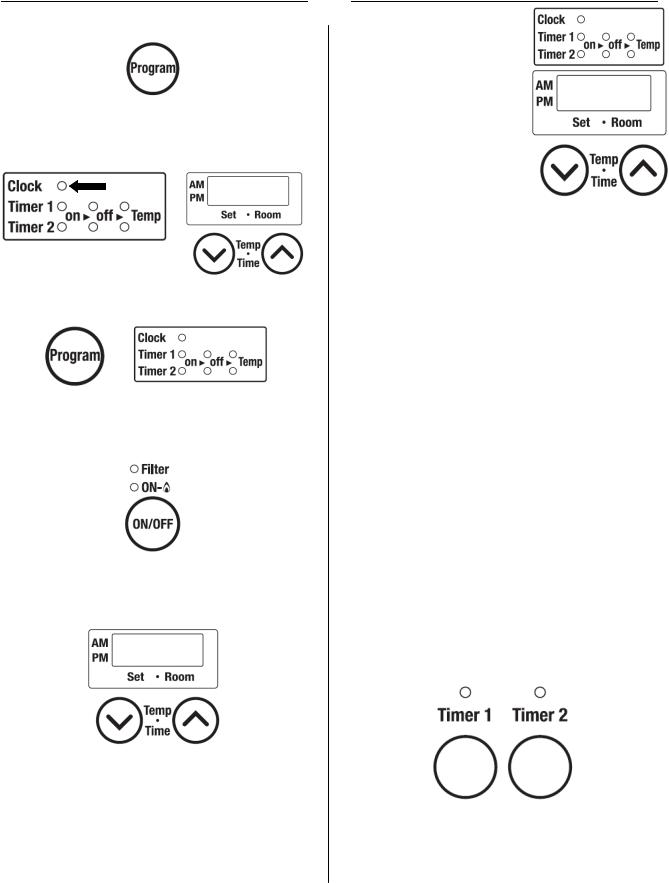
Setting the Clock
1.Press the “Program” button.
2.The light next to “Clock” should be flashing. Press the up and down arrows to set the time. Holding down either of the arrow keys will change the time more quickly.
3.Press the “Program” button until none of the time options are flashing up.
Operating the Heater Manually
1.Turn the heater on by pressing the “ON/OFF” button.
2.Press the up or down arrows to set the temperature. The left display shows the temperature setting. The right display shows the room temperature.
The thermostat automatically modulates the burner and the fan to maintain the temperature setting.
The temperature settings available are:
LO - burner is on minimum combustion
60° F - 80° F in one degree increments
HI - burner is on maximum combustion
Setting and Operating the Timers
Confirm the clock is correct.
NOTE: The clock will have to be reset in case of a power failure. However the timers will retain their settings.
The heater will start before the programmed starting time in order to heat the room by the programmed starting time.
The timers can be set while the heater is on or off. To operate the timer, the heater must be on.
Setting the timers:
1.Press the “Program” button twice to set Timer 1.
2.The light next to “Timer 1 on” should be flashing. Press the up or down arrows to set the start time. Holding down either of the arrow keys will change the time more quickly.
3.Press the “Program” button again so that the Timer 1 off position is flashing. Press the up or down arrows to set the end time. Holding down either of the arrow keys will change the time more quickly.
4.Press the “Program” button again so that the Timer 1 Temp Position is flashing. Press the up or down arrows to set the temperature.
5.Press the “Program” button again to set the times for Timer 2. Follow the same steps above to set the start and end times.
6.Press the “Program” button until none of the time options are flashing up.
Operating the timers:
To operate the heater using a Timer, press the ON/ OFF button and the appropriate Timer button. The heater will operate from the start to end times you have entered for that Timer. It will operate at the temperature setting that has been set for the heater. The timer can be set while the heater is operating.
While in standby, the timer LED will be on with a solid light. When operating the LED will be flashing.
8 |
Rinnai Corporation EX38C Manual |

Override Function
This function is used only when the heater is in Timer operation.
It allows you to “override” the reset timer setting until the beginning of the next Timer period.
For example, if the heater is ON, pressing the “Override” button will turn the heater OFF until the next period. If
the heater is OFF, pressing the “Override” button will turn the heater ON, and allow you to select a temperature setting, until the next period. The heater will remain on until the next timer period or until the Override function is turned off.
When in override function, pressing the “Override” button will return the heater to the operation of the current timer period.
Economy (Energy Saving Mode)
The Economy mode can only be set while the heater is operating (heating). Once it is set, it will remain in the system memory until deactivated.
1.To turn the Economy mode on, press the “Economy” button. The Economy indicator is lit.
The Economy mode now remains in the system memory.
If the appliance is turned off manually, or stops heating as a result of an OFF timer period, the “Economy “ indicator will go out.
Whenever the appliance starts heating again, the “Economy” indicator will light.
2.To turn the Economy mode off, press the “Economy” button. The “Economy “ indicator will go out.
The Economy mode can only be turned off while the heater is operating (heating) and when the “Economy” indicator is lit.
Economy Mode Information
After the room is heated initially, the air temperature may be dropped to a lower level without affecting comfort. The Economy Mode reduces the temperature by 2 ºF, 30 minutes after the room temperature setting is reached. After another 30 minutes, it reduces the temperature setting by another 2 ºF, effectively saving energy. The room temperature setting will drop up to a total of 4 ºF.
The Economy Mode will not operate if the heater is under capacity for the room size.
Rinnai Corporation EX38C Manual |
9 |
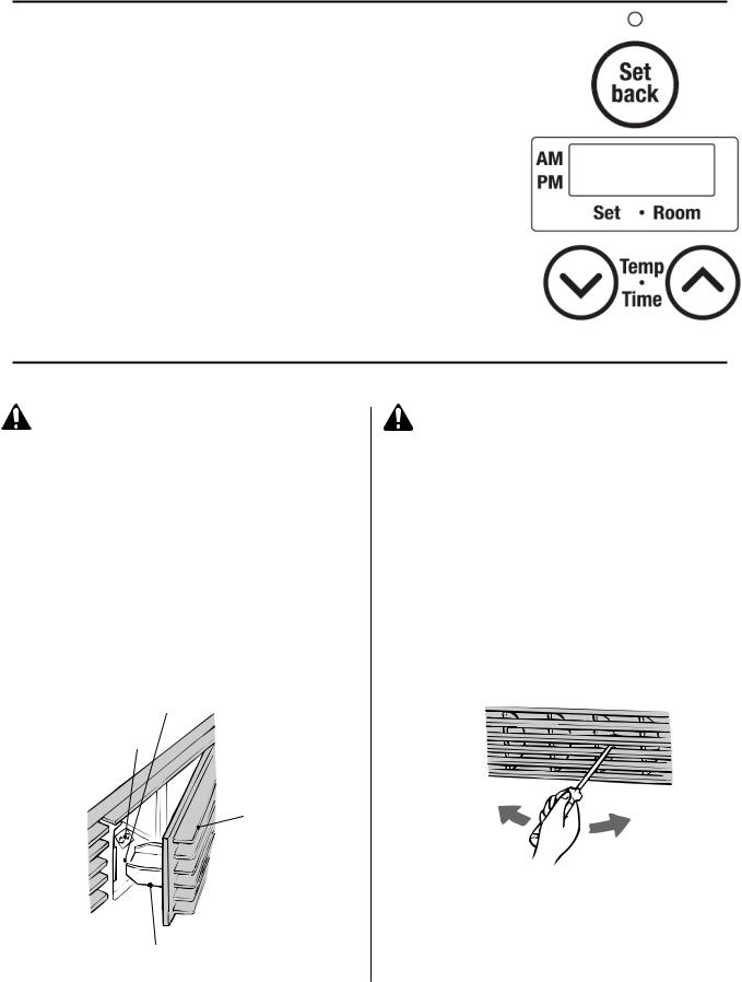
Set Back
This function allows a minimum room temperature to be pre-set, between 38ºF and 78ºF (in 1ºF increments). This temperature should be set below the room temperature setting. The default setting is 60ºF. Once the Set back function is selected the appliance will start heating whenever the room temperature falls below the selected temperature, regardless of timer or manual settings.
Follow these steps to set and operate the Set back feature:
1.Make sure the heater is turned OFF.
2.Press the “Set back” button. The light above the button will come on.
3.Press the up and down buttons to set the minimum temperature.
When the “Set back” indicator is on, frost protection is operating, and will always prevent the room temperature from falling below the pre-set minimum temperature (as long as electric power and gas is supplied).
To turn this feature off, press the “Set back” button.
The unit will retain its ON or OFF setting after a power failure. (Set Back feature is on by factory default.)
Humidifier and Air Flow Direction
Adding Water to the Humidifier
CAUTION |
Do not fill the tray while the |
|
appliance is in operation. |
|
|
|
Close the door after filling. |
|
The humidifier tray and |
|
surrounding area are hot |
|
when the appliance is on. |
|
|
To fill the tray, open the door as shown in the diagram and pour water into the tray using the spout built into the door. The air will be humidified as it passes over the water in the tray.
During operation a small amount of condensation is produced in the flue system and drains into the humidifier tray.
If the water overflows from the water level hole, then do not add any more water.
Humidifier Tray
Max. Fill Line
Access Door
 Pull
Pull
Filler Spout
Do not force door open too far.
Close door during operation.
Adjusting Air Flow Direction
CAUTION |
Do not adjust the air flow |
|
louvers while warm air is |
|
|
|
flowing. |
|
|
The vertical louvers may be adjusted to move the air flow more to the right or to the left.
Use a screw driver or similar object to bend each louver to the desired position.
Do not bend repeatedly (no more than 5 times) or else the louver will break.
The horizontal louvers (which determines the vertical air flow direction) are fixed and cannot be adjusted.
10 |
Rinnai Corporation EX38C Manual |
Care and Maintenance
Maintenance
All maintenance and service are to be performed by a qualified service technician, preferably one who has attended Rinnai service training classes on the Direct Vent products.
The appliance should be inspected annually by a qualified service technician. More frequent cleaning may be required due to excessive lint from carpeting, bedding material, etc. It is imperative that control compartments, burners, and circulating air passage ways of the appliance be kept clean.
Any screen or guard removed for servicing the appliance must be replaced prior to operating the appliance. Clean as follows:
1.Turn heat off. Allow to cool for one hour.
2.Remove the front panel by removing three screws.
3.Use pressurized air to remove dust from the main burner, heat exchanger, and fan blades.
4.Use soft dry cloth to wipe cabinet.
Do not use wet cloth or spray cleaners on the burner.
The flue should be inspected annually for blockages or damage.
Motors are permanently lubricated and do not need periodic lubrication. Keep fan and motor free of dust and dirt by cleaning annually.
Verify proper operation after servicing.
When attaching the front panel, take care not to clip or pinch any electric cords to prevent electric shock.
Care of Exterior
Dampen soft cloth with warm water. Wring water out well and wipe the unit.
Do not use volatile substances such as benzene or thinners. They cause fading of the paint and deformation of the resin.
 CAUTION
Prevent dust from accumulating on the power cord, side covers, and parts behind the appliance.
 CAUTION
Keep the area around flue terminal free of snow and ice. The appliance will not function properly if the intake air or exhaust is impeded by obstructions.
Refer to the Flue Terminal Clearances. The clearance in Ref. A should be maintained from any snow accumulation.
Filters
Dirty filters reduce the air flow and the appliance’s ability to produce heat. The filters should be cleaned frequently during the heating season. If the filters become blocked the filter indicator lamp will flash and the appliance will beep. Eventually the appliance will turn off and the Temperature Level lamp 14 will light, indicating a fault code.
To clean the filters, the appliance should be OFF and cool. Remove the filter and clean it using a soft dry cloth or vacuum. If the filter is greasy wash with warm soapy water, rinse, and dry completely.
Do not use the appliance without the filters installed.
Visual Inspection of Flame
Check that the burner flames are operating normally. The flame can be seen through the circular window.
When operating normally the burner flame should appear as long, clear, blue, stable, streaks. Yellow flames or an orange color is abnormal and maintenance is required.
NORMAL
Flame Rod
Long, clear, blue, stable flames
ABNORMAL
Flame Rod 
Yellow flames or orange color
Rinnai Corporation EX38C Manual |
11 |

Before Making a Service Call
Before making a service call please check the following:
At Ignition:
Heater does not operate.
Warm air does not flow when the burner lights.
Smoke or strange smells are produced on the first trial light up after installation.
Sharp clicking noises at ignition, or when unit cuts down on the thermostat, or goes out.
Is the heater plugged in?
Have the fuses or breaker blown at the fuse box / breaker panel? Is there a power failure?
Is the air filter blocked?
Is anything blocking the outlet for the hot air? Is the flue blocked?
The fan is started automatically after a short delay.
This is to allow the heat exchanger to warm up, helping to avoid cold draughts.
This is caused by grease or oil and dust on the heat exchanger and will stop after a short time.
This is simply expansion noise from the heat exchanger.
During Combustion:
Clunking noise when the thermostat operates.
Unit is not heating room.
Air filter is blocked or the louvers are blocked or obstructed.
Heater will not re-ignite after overheating.
When the unit is turned off.
Convection fan continues to run after turning OFF.
Other Points:
Steam is discharged from the flue terminal .
This is the sound of the solenoid gas valves opening and closing.
Is the air filter blocked?
Is the set temperature high enough?
Is the warm air outlet blocked by anything?
Are the doors and windows of the room closed?
Was the appliance correctly sized for the space?
Allow heater to cool, clean air filter, operate again.
Even after unit has cooled down, the heater does not ignite again. Repair is necessary.
Contact a qualified / authorized service provider.
This is to remove the residual heat from the heat exchanger. The fan will stop when the heater cools down.
High efficiency appliances tend to discharge water vapor on cold days. This is normal.
Unit cuts off without apparent reason.
Check whether filters are blocked. Dirty filters will cause the heater to overheat.
Power Failure.  Switch OFF, then ON again when power is restored to re-set controls.
12 Rinnai Corporation EX38C Manual

Fault Codes
If there is a malfunction the appliance may shut down as a safety precaution and display a fault code to assist in diagnosing the problem. The fault code will flash in the display on the control panel. When making a service call, this code will assist with diagnosing the fault.
You may be able to clear the fault code by turning the heater off and then on again. If the fault code remains or returns on the next operation, contact Rinnai or your nearest service agent and arrange for a service call.
CODE DISPLAYED |
FAULT |
REMEDY |
|
|
|
|
|
|
|
Check that gas is turned ON. |
|
11 [3] |
Ignition Failure |
Check that the vent termination is not blocked. |
|
Refer to the Restart Function explanation. |
|||
|
|
||
|
|
Service call if repeated. |
|
|
|
|
|
14 |
Overheat |
Clean filter. |
|
Service call if repeated. [1] |
|||
|
|
||
|
|
|
|
16 |
Room Overheat |
Lower room temperature to less than 104°F (40°C). |
|
|
|
|
|
30 |
Overheat Temperature Sensor |
|
|
Disconnection (open circuit) |
|
||
|
|
||
|
|
|
|
31 |
Room Temperature Sensor |
|
|
Disconnection (open circuit) |
|
||
|
|
||
|
|
|
|
32 |
Room Temperature Sensor |
|
|
short circuit |
|
||
|
|
||
|
|
|
|
33 |
Overheat Temperature Sensor |
|
|
Disconnection (open circuit) |
|
||
|
|
||
|
|
|
|
34 |
Overheat Temperature Sensor |
|
|
short circuit |
|
||
|
|
||
|
|
|
|
35 |
Overheat Temperature Sensor |
Service call. |
|
short circuit |
|||
|
|
||
|
|
|
|
49 |
Sensor Breakdown |
|
|
|
|
|
|
53 |
Sparker Failure |
|
|
|
|
|
|
61 |
Combustion Fan Failure |
|
|
|
|
|
|
62 |
Convection Fan Failure |
|
|
|
|
|
|
70 |
Faulty ON/OFF Switch or |
|
|
Faulty “Set Back” Switch |
|
||
|
|
||
|
|
|
|
71 |
Faulty Solenoids |
|
|
|
|
|
|
72 |
Faulty Flame Rod |
|
|
|
|
|
|
73 |
Communication Error |
Turn heater OFF, then ON again. |
|
|
|
|
|
81 |
Solenoid Valve Failure |
Service Call |
|
|
|
|
|
99 |
Flue Block |
Check around the flue terminal for blockage. [2] |
|
|
|
|
[1]If the fusible link needs replacement, it must be done by a qualified service agency. In addition, the cause of the overheat needs to be determined. The fusible link is a one use safety device that breaks to shut off the appliance.
[2]Remove any obstructions. The flue needs to be kept clear to expel exhaust gases. If the appliance fails to operate contact a qualified service agency.
[3]Only this code is dim.
Rinnai Corporation EX38C Manual |
13 |

Restart Function
If there is a power failure while the appliance is on, then the appliance will start automatically when the power is restored.
If the appliance fails to ignite, the appliance will attempt ignition after 1 hour. The “Ignition Failure” fault code, 11, will appear during that hour and disappears after a successful ignition. If ignition fails again, then the fault code will remain and another attempt to ignite will occur in 1 hour. The fault code is not stored in the fault code history.
If the flame is extinguished during forced combustion then the appliance will attempt ignition after 1 hour. The “Ignition Failure” fault code, 11, will appear during that hour and disappears after a successful ignition. Forced combustion takes place for about 40-80 seconds after ignition. After this time, the temperature control logic controls the combustion.
If the flame is extinguished (burner combustion failure) while the temperature control logic is operating the appliance, then the appliance will immediately attempt ignition. No fault code will appear.
In summary, if the ignition fails or the flame is extinguished during forced combustion then the appliance will attempt to restart after 1 hour. If the flame is extinguished after this period then the appliance will immediately attempt ignition.
Troubleshooting
Problem |
Burnerdoesn’t ignite |
Unusualcombustion |
Combustionstops duringoperation |
Smellof gas |
Noisyignition |
Takestoo long to warmthe room |
ONNoindicator |
||||||
Cause |
|
|
|
|
|
|
Not Plugged In |
|
|
|
|
|
|
Power Failure
(Initial Installation)
Air In Gas Pipe
Gas Filter Blocked
Miss Ignition
Flue terminal obstructed
Flue manifold not connected
Louver obstructed
Air filter blocked
Gas Escape
Child Lock Set
Gas turned off at meter, tank, or valve.
ON Timer is set
14 |
Rinnai Corporation EX38C Manual |
Remedy
Plug In
Push On/Off button to attempt restart after power is restored.
Purge air (Installer)
Service Call
Service Call
Clear obstruction
Service Call
Clear obstruction
Clean filter
Service Call
Cancel Child Lock
Turn gas on
Cancel “ON” Timer or push override button

Installation Instructions
General Instructions
 WARNING
Do not use substitute materials.
Use only parts certified with the appliance.
NOTICE |
If installation is at a location above |
|
|
2001 ft (610 m), then follow the Adjust |
|
|
||
|
Gas Pressure Settings procedure. |
|
|
Appliance input ratings are based on |
|
|
sea level operation and need not be |
|
|
changed for operation up to 2000 ft |
|
|
(610 m) elevation. |
|
|
|
|
A qualified service technician should install the appliance and inspect it before use.
If you move, check the gas type in your new area. The local gas authority will be able to advise on local regulations.
The installation must conform with local codes or, in the absence of local codes, with the National Fuel Gas Code, ANSI Z223.1/NFPA 54, or the Natural Gas and Propane Installation Code, CSA B149.1.
A manufactured home (USA only) or mobile home OEM installation must conform with the
Manufactured Home Construction and Safety Standard, Title 24 CFR, Part 3280, or, when such a standard is not applicable, the standard for
Manufactured Home Installations, ANSI Z225.1, or the standard for Gas Equipped Recreational Vehicles and Mobile Housing, CSA Z240.4.
The appliance, when installed, must be electrically grounded in accordance with local codes or, in the absence of local codes, with the National Electrical Code, ANSI/NFPA 70, or the Canadian Electrical Code, CSA C22.1.
The appliance and its appliance main gas valve must be disconnected from the gas supply piping system during any pressure testing of that system at test pressures in excess of 1/2 psi (3.5 kPa).
The appliance must be isolated from the gas supply piping system by closing its equipment shutoff valve during any pressure testing of the gas supply piping system at test pressures equal to or less than 1/2 psi (3.5 kPa).
If the flooring is carpet, tile, or other combustible material other than wood, then the appliance must be installed on a metal or wood panel extending the full width and depth of the appliance.
This appliance discharges a large volume of warm air next to the floor. Any particles in the air such as cigarette smoke could cause discoloration in nylon carpets containing dyes or vinyl surfaces.
This appliance is not designed to built in.
This appliance is only for use with the type of gas indicated on the rating plate. This appliance is not convertible for use with other gases unless a certified kit is used. If conversion of the unit is needed, conversions must be performed by a qualified service provider at the owner’s expense.
This appliance must not be connected to a chimney flue serving a separate solid-fuel burning appliance.
Rinnai suggests that a dedicated electrical circuit with a 120VAC, 60 Hz, 10 amp power source be used.
A test plug are provided for testing of manifold differential pressure. It is located on the modulating gas valve.
The appliance should be correctly sized for the space it is required to heat. It is recommended that an Industry standard BTU Heat Loss Calculation be conducted to determine the proper sizing.
Follow the installations instructions and those in Care and Maintenance for adequate combustion and ventilation air.
The flow of combustion and ventilation air shall not be obstructed.
Clearances to
access the |
|
|
3” |
|
|
|
|
appliance during |
10” |
clearance for |
(76 mm) |
|
|||
servicing are 10 |
(254 mm) |
maintenance |
|
|
|
||
inches (254 mm) |
|
|
|
from the sides, |
|
|
|
40 inches (1 m) |
|
|
|
from the front, |
|
|
|
and the area |
|
|
|
shown above |
|
|
|
the appliance in |
|
|
|
the picture. |
|
|
|
6” (153 mm)
Rinnai Corporation EX38C Manual |
15 |

Gas Connection
 WARNING
When connecting the gas valve or other gas components in the gas line, use a backup wrench to ensure the connection is gas tight.
The gas supply line shall be gas tight, sized and so installed as to provide a supply of a gas sufficient to meet the maximum demand of the heater without loss of pressure.
A shut off valve and appliance connector valve should be installed in the upstream of the gas line to permit servicing.
Flexible pipe and any appliance connector valve used for gas piping shall be types approved by nationally recognized agencies.
Any compound used on the threaded joint of the gas piping shall be a type which resists the action of liquefied petroleum gas (propane / LPG).
After completion of gas pipe connections all joints including the heater must be checked for gas tightness by means of leak detector solution, soap and water, or an equivalent nonflammable solution, as applicable. (Since some leak test solutions, including soap and water, may cause corrosion or stress cracking, the piping shall be rinsed with water after testing, unless it has been determined that the leak test solution is non-corrosive.)
Check the gas supply pressure immediately upstream at a location provided by the gas company. Supplied gas pressure must be within the limits shown in the Specifications section.
Refer to an approved pipe sizing chart if in doubt about the size of the gas line.
Install manual gas cut-off valve so that it can be accessed for easy operation. Do not conceal manual cut-off valve behind back spacer.
Clearances to Combustibles
When determining where to install the appliance the clearances to combustibles shown in the figure must be followed. Also refer to the Safety Behaviors and Practices section.
Rinnai recommends 10” (254 mm) clearance from the top and on both sides for servicing.
NOTICE |
The 40 inch (1 meter) clearance |
|
from the front of the appliance does |
||
|
||
|
not include flooring material or |
|
|
carpeting that is less than 1.2 inches |
|
|
(30 mm) in height. |
|
|
|
0” (0 mm)
10"(250mm)
0"
2"
(50mm)
2" (50mm)
40" (1m)
16 |
Rinnai Corporation EX38C Manual |

TERMINATION
Clearance in Ref. A also applies to anticipated snow line
SNOW
EX38C Corporation Rinnai |
D |
Manual |
|
|
E |
 B
B
L
17
This diagram shows the minimum clearances from the flue.
INSIDE
CORNER DE TAIL
G
A
C 


FIXED

 CLOSED


 OPERABLE
F 
B 
H
|
|
B |
I |
M |
|
|
|
|
|
B |
|
FIXED |
|
K |
|
CLOSED |
|
||
|
|
|
||
|
|
|
|
|
|
OPERABLE |
|
|
|
B |
J |
|
|
|
|
|
|
|
|
|
B |
|
|
|
|
A |
|
X AIR SUPPLY INLET |
|
|
|
|
||
|
|
|
V VENT TERMINAL |
|
|
|
|
AREA WHERE |
|
|
|
|
TERMINAL IS NOT |
|
|
|
|
PERMITTTED |
|
Clearances Terminal Flue

Flue Terminal Clearances
Ref |
Description |
Canadian Installations |
US Installations |
|
|
|
|
|
|
|
Clearance above grade, veranda, |
|
|
|
A |
porch, deck, or balcony. (Take into |
12 inches (30 cm) |
12 inches (30 cm) |
|
|
account the anticipated snow line) |
|
|
|
|
|
|
|
|
B |
Clearance to window or door that may |
12 inches (30 cm) |
9 inches (23 cm) |
|
be opened |
||||
|
|
|
||
|
|
|
|
|
C |
Clearance to permanently closed |
* |
* |
|
window |
||||
|
|
|
||
|
|
|
|
|
|
Vertical clearance to ventilated soffit, |
|
|
|
D |
located above the terminal within a |
* |
* |
|
horizontal distance of 2 feet (61 cm) |
||||
|
|
|
||
|
from the center line of the terminal |
|
|
|
|
|
|
|
|
E |
Clearance to unventilated soffit |
* |
* |
|
|
|
|
|
|
F |
Clearance to outside corner |
* |
* |
|
|
|
|
|
|
G |
Clearance to inside corner |
20 inches (50 cm) |
20 inches (50 cm) |
|
|
|
|
|
|
|
Clearance to each side of center line |
3 feet (91 cm) within a height |
|
|
H |
extended above meter/regulator |
15 feet (4.5 m) above the |
* |
|
|
assembly |
meter/regulator assembly |
|
|
|
|
|
|
|
I |
Clearance to service regulator vent |
3 feet (91 cm) |
* |
|
outlet |
||||
|
|
|
||
|
|
|
|
|
|
Clearance to nonmechanical air supply |
|
|
|
J |
inlet to building or the combustion air |
12 inches (30 cm) |
9 inches (23 cm) |
|
|
inlet to any other appliance |
|
|
|
|
|
|
|
|
K |
Clearance to a mechanical air supply |
6 feet (1.83 m) |
3 feet (91 cm) above if within |
|
inlet |
10 feet (3 m) horizontally |
|||
|
|
|||
|
|
|
|
|
|
Clearance above paved sidewalk or |
|
|
|
L |
paved driveway located on public |
7 feet (2.13 m) |
* |
|
|
property |
|
|
|
|
|
|
|
|
|
|
12 inches (30 cm) to non- |
12 inches (30 cm) to non- |
|
M |
Clearance under veranda, porch, deck, |
flammables |
flammables |
|
or balcony |
24 inches (60 cm) to |
24 inches (60 cm) to |
||
|
||||
|
|
flammables |
flammables |
A vent shall not terminate directly above a sidewalk or paved driveway that is located between two single family dwellings and serves both dwellings.
Permitted only if veranda, porch, deck, or balcony is fully open on a minimum of two sides beneath the floor.
For clearances not specified in ANSI Z223.1/NFPA 54 or CSA B149.1, clearances are in accordance with local installation codes and the requirements of the gas supplier.
18 |
Rinnai Corporation EX38C Manual |

Dimensions
inches (mm) |
12.63 (320) |
|
8.1 (205) |
4.5 (113)
13 (330)
36.63 (930)
Gas Connection
3.63 (92)
|
|
|
Air Inlet |
|
|
|
|
Exhaust Pipe |
|
|
|
|
|
20.69 (526) |
5.13 (130) |
.31 (20) |
9.31 (250) |
12.31 (313) |
21.63 (550) |
26.38 (670) |
|
Rinnai Corporation EX38C Manual |
|
|
|
19 |
|
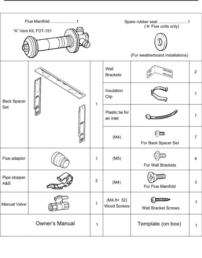
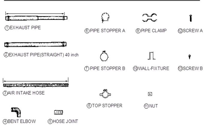
Installation Parts
The following items are included with the appliance:
(Attached to unit)
20 |
Rinnai Corporation EX38C Manual |
11" Cavity Opening
(280 mm)
Drilling Flue Hole
Ensure that there are no gas or water lines, or electrical circuits in the wall location where the flue hole is to be drilled.
Drill the flue hole using a 3 1/8 inch (80 mm) drill. A |
|
template is provided on the appliance carton/box. |
R11" |
|
|
The center of the hole must be located anywhere |
|
within the shaded area, unless extension kits are |
|
used. See the dimensions diagram. |
|
For weatherboard walls, drill through the center of |
|
7/16"8 (214mm) |
|
the weatherboard from the outside first and then |
|
through the plasterboard.
(R27
9
mm
)
Flue Hole
3 1/8" (80 mm)
(217 mm)
Template is on the appliance carton/box.
Attach Wall Brackets
Attach the wall brackets as shown. A template is provided.
Attach Back Spacers
Attach side back spacers to both sides of the appliance with 2 screws each.
Rinnai Corporation EX38C Manual |
21 |
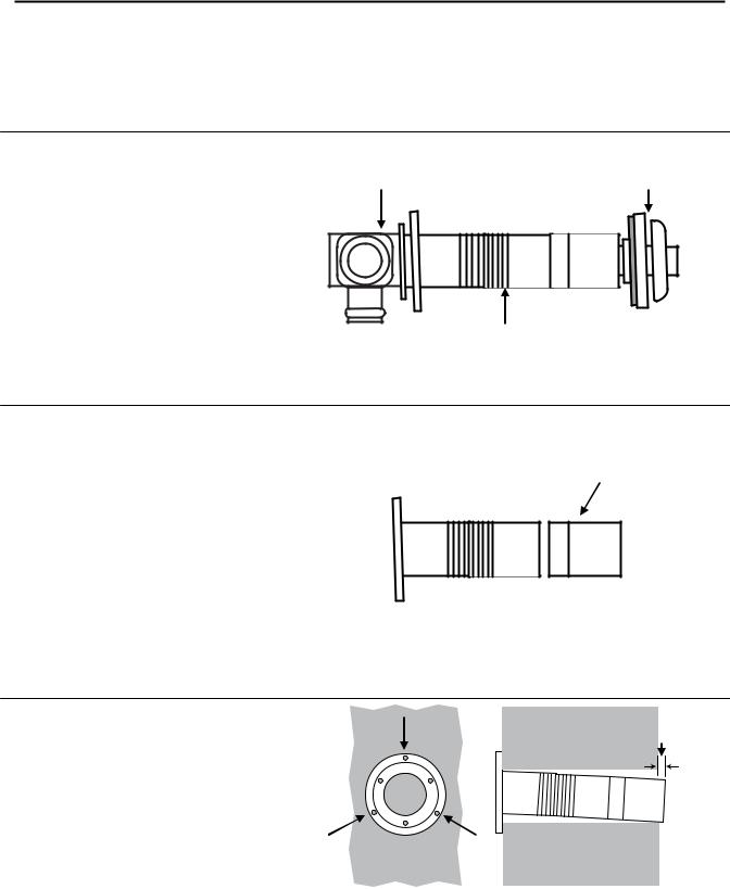
Flue Manifold Installation
The flue manifold must exhaust to the outside. Do not exhaust into other rooms.
The flue manifold is not designed to be positioned under floors or below the heater.
The termination cannot be vertical.
This appliance can only be used with one of the five types of Rinnai flue kits. The flue kits and their dimensions are listed on the previous page.
Refer to the Flue Terminal Clearances section.
1.Disassemble the flue manifold The flue consists of 3 parts:
|
Inside Connection |
Terminal |
sleeve |
|
inside connection
outside terminal
Disassemble the flue manifold by first pulling |
|
out the inside connection. To remove the |
|
outer terminal pull and release the two |
|
internal ties and then pull out the outer |
|
terminal. |
Sleeve |
Clearance to combustibles for the sleeve and flanges is zero inches.
2.Adjust the sleeve length
Measure wall thickness through previously drilled 3 1/8 inch (80 mm) hole.
The end of the sleeve should protrude 3/16 - 3/8 inch (5-10 mm) from the outside wall.
The sleeve is threaded for adjustment. Adjust the sleeve length to wall thickness plus 3/16 - 3/8 inch (5-10 mm).
NOTE: Do not extend beyond the red line.
For other than the “S” type flue manifold, if a shorter length is necessary an extension can be removed. Cut the plastic and remove the extension.
Remove extension if necessary
3.Attach the sleeve
Attach to the inside wall using 3 screws arranging the flange so that the marking “TOP” is at the top.
The flange is offset 2° to allow the condensate drain to the outside.
3 screws
sleeve should extend 3/16 - 3/8 in (5-10 mm)
22 |
Rinnai Corporation EX38C Manual |

Flue Manifold Installation
4. |
Install the Terminal |
Terminal seal |
|
Check that the terminal seal is in place. For |
|
|
|
|
|
weatherboard walls, add the second seal next |
|
|
to the terminal seal to compensate for |
|
|
weather board angle. |
|
|
From the outside insert the terminal into the |
|
|
sleeve with the marking “TOP” at the top. |
Terminal |
|
The left hand side locking tie should be |
|
|
|
|
|
marked “LEFT”. |
|
|
|
Locking tie |
6. |
Lock the ties |
|
|
Pulling hard on the left and right hand ties, |
Locking ties |
|
clip the ties over the notches inside the |
Sleeve |
|
sleeve. You should be able to pull the ties 2 |
|
|
or 3 notches past the starting point. Cut the |
|
|
ties, leaving about 3/4 inch (20 mm) past the |
|
|
notch. Bend the ties back into the sleeve and |
|
|
parallel to the wall. |
|
7. Insert Inside Connection Assembly
Push the assembly into the terminal tube, ensuring that the seal is in place on the inner tube.
Attach the inside connection with 3 screws. The inner connection can still be turned to install the screws.
3 screws
Rinnai Corporation EX38C Manual |
23 |
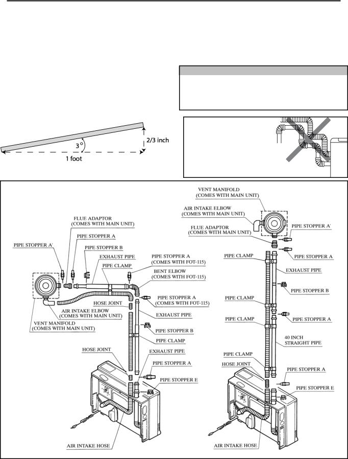
Extension Kit Installation
If necessary, extension kits are available to extend the exhaust line and air intake hose between the manifold and the appliance. The maximum vent length is 13 feet (4 m) with 2 bends. The bent pipe attached to the appliance does not count toward the max limit of 2 bends.
Horizontal sections should be sloped 3º to drain condensate. (3º equals 2/3 inch drop per foot of vent.) The direction should be to the outside (if local codes allow) or toward the appliance. Do not allow any low points in the exhaust line where condensate will collect.
Vent extensions installed in unconditioned air space
must be insulated with high temperature insulation and must be accessible.
Vent extensions must not be concealed per NFPA 54 and must be accessible allowing inspection and repair. Decorative covers are available from Rinnai.
NOTE
The EX38C is capable of two vent length settings: Short Vent: 0 - 7ft + 1 elbow
Long Vent: 7ft + 1 elbow - 13ft + 2 elbows
INCORRECT
Too many bends (limit is 2)
Air intake hose is above exhaust pipe
Slope horizontal sections 3º (2/3 inch drop per foot of vent.)
CORRECT
24 |
Rinnai Corporation EX38C Manual |

Extension Kit Installation
CAUTION |
Use the pipe stoppers, connectors, clamps, and screws according to these instructions in |
|
order to ensure no leakage of exhaust gases. |
|
|
|
|
Clearances |
exhaust pipe to combustibles |
1 inch (25.4 mm) |
|
|
|
|
|
|
exhaust pipe to non-combustibles |
zero |
|
|
|
|
|
Clamps |
Exhaust pipe |
||
Both the exhaust line and air intake hose are |
|
|
|
supported by clamps which are attached to the wall. |
|
|
|
A wall fixture can be used to offset the clamp from the |
|
|
|
wall. Use Screw B to attach the wall fixture to the |
|
|
|
wall. If the wall fixture is not used then use Screw A |
|
|
|
and the nut to attach the clamp to the wall. |
|
|
|
The air intake hose should always be underneath the |
|
|
|
exhaust line so that in case the air intake hose sags it |
|
|
|
will not come into contact with the exhaust line. |
|
|
|
|
|
Air intake hose |
|
Exhaust pipe
Air intake hose
Installing the Exhaust Line
The exhaust line is connected between the bent pipe at the rear of the heater and the exhaust port on the flue manifold.
To connect exhaust pipes with other straight pipes or bends, fit the male end into the female end. Use pipe stopper A to clamp the connection.
Use pipe stopper B to fix the length on the adjustable exhaust pipes. Do not extend these pipes beyond the red line.
Do not cut the exhaust pipe. Use the adjustable pipes if necessary.
To bend the elbow, insert exhaust pipes into both ends for additional leverage. Bend to desired angle.
Do not straighten the bent pipe attached to the appliance.
Connecting the Air Intake Hose
The air intake hose is connected between the air connection at the rear of the heater and the air intake port on the flue manifold.
Push the air intake hose onto the flue manifold and secure with the plastic cable tie.
Join air intake hoses by screwing the hose joint half of its length into the air intake hose and then screwing another air intake hose into the hose joint.
NOTICE |
Do not cut the intake hose. Cutting |
|
the intake hose may result in noise. |
|
|
|
|
Male end |
Female end |
Pipe stopper B |
|


 Pipe stopper A
Adjust the
The lengths of the air intake hose and the exhaust pipe must be the same in order for the appliance to operate properly. The hose can be cut to the required length. Deburr all rough edges. Do not cut the hose attached to the appliance.
Support the air intake hose with pipe clamps.
Hose joint
air intake hoses
Rinnai Corporation EX38C Manual |
25 |
Extension Kit Installation
AFOT-102 (12.2-21.1 inch)
BFOT-103 (21.9-40.4 inch)
Extension Kits and Parts
AFOT-102 (21.1 inch)
BFOT-103 (51.2 inch)
CFOT-114 (90.6 inch)
Item |
Description |
Part No. |
FOT-102 |
FOT-103 |
FOT-114 |
FOT-115 |
|
|
|
|
|
|
|
1 |
Exhaust Pipe (adjustable) |
FOT 111-1 |
1 |
|
|
|
|
12.2-21.1 in (311-536 mm) |
|
|
|
|
|
|
|
|
|
|
|
|
1 |
Exhaust Pipe (adjustable) |
FOT 112-1 |
|
1 |
1 |
|
|
21.9-40.4 in (556-1026 mm) |
|
|
|
|
|
|
|
|
|
|
|
|
2 |
Exhaust Pipe - 39.4 in (1000 mm) |
FOT 114-3 |
|
|
1 |
|
|
|
|
|
|
|
|
3 |
Air Intake Hose - 29.5 in (750 mm) |
RHF 1000-130-e |
1 |
|
|
|
|
|
|
|
|
|
|
3 |
Air Intake Hose - 51.2 in (1.3 m) |
RHF 1000-130-b |
|
1 |
|
|
|
|
|
|
|
|
|
3 |
Air Intake Hose - 90.6 in (2.3 m) |
RHF 1000-130-f |
|
|
1 |
|
|
|
|
|
|
|
|
4 |
Bent Elbow |
FOT 025-4 |
|
|
|
1 |
|
|
|
|
|
|
|
5 |
Hose Joint |
RFOT 226-001 |
1 |
1 |
1 |
|
|
|
|
|
|
|
|
6 |
Pipe Stopper A |
1001F-250 |
1 |
1 |
2 |
2 |
|
|
|
|
|
|
|
7 |
Pipe Stopper B |
FOT 111-6 |
1 |
1 |
1 |
|
|
|
|
|
|
|
|
8 |
Top Stopper |
FOT 062-7 |
1 |
1 |
1 |
|
|
|
|
|
|
|
|
9 |
Pipe Clamp |
FOT 064-11 |
2 sets |
3 sets |
4 sets |
|
|
|
|
|
|
|
|
10 |
Wall Fixture |
FOT 064-12 |
2 |
3 |
4 |
|
|
|
|
|
|
|
|
11 |
Nut |
FOT 062-10 |
2 |
3 |
4 |
|
|
|
|
|
|
|
|
12 |
Screw A |
ZAA0420SC |
2 |
3 |
4 |
|
|
|
|
|
|
|
|
13 |
Screw B |
CP-30408 |
4 |
6 |
8 |
|
|
|
|
|
|
|
|
26 |
Rinnai Corporation EX38C Manual |
|
|
|
||
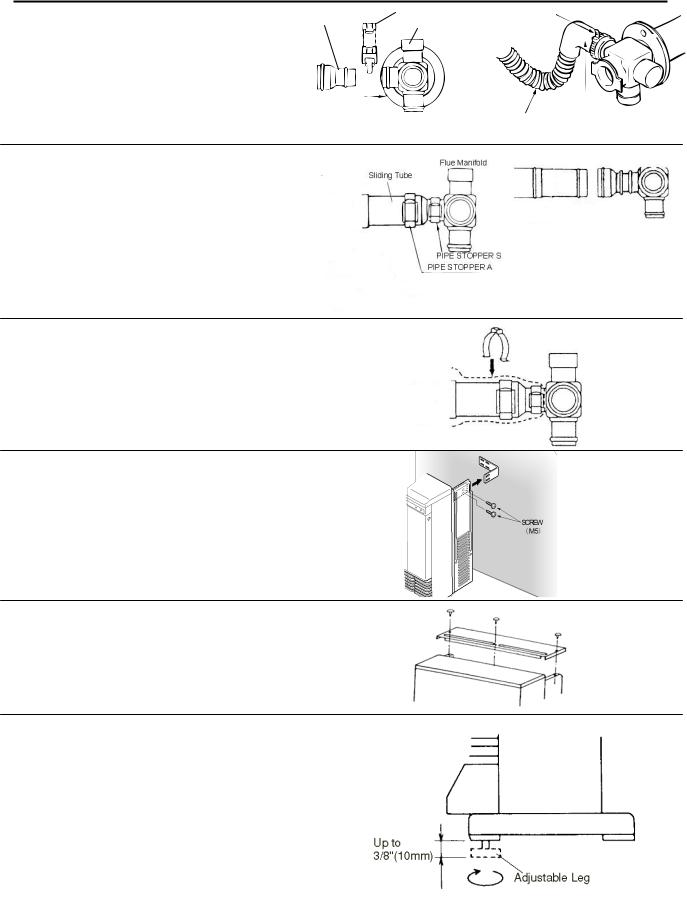
Connecting the Appliance
1. Attach flue adapter to the flue manifold with |
|
Pipe stopper S |
Plastic tie |
Flue Adapter |
|
||
Flue Manifold |
|
||
pipe stopper S. |
|
|
|
|
|
|
|
2. Attach the air inlet hose to the flue manifold. |
|
|
|
Secure with plastic tie. The unused inlet is |
|
|
|
plugged with the rubber cap supplied on the |
|
|
Inlet elbow |
manifold. |
|
|
|
|
|
|
|
|
|
|
Inlet hose |
3.Connect the vent sliding tube with pipe stopper S and E. The sliding tube should not be extended beyond the red line. The red line should not be visible after sliding the tube into the vent outlet.
4.Slide the insulation sleeve up to the flue manifold and slip the securing clip over the sleeve as shown.
5.Attach the appliance to the wall brackets, using 2 screws at each bracket.
6.Attach the back spacer with 3 screws to the top of the appliance.
7.If necessary, the appliance can be leveled using the adjustable legs under the front right and left legs.
Rinnai Corporation EX38C Manual |
27 |

Adjust Gas Pressure Settings
Complete these instructions for altitude and vent length. (Default altitude: 0ft - 2,000ft. Default vent length: 0 - 7ft+1 elbow )
For high altitude installations in Canada, the conversion shall be carried out by a manufacturer’s authorized representative, in accordance with the requirements of the manufacturer, provincial or territorial authorities having jurisdiction and in accordance with the requirements of CAN/CGA-B149.1 or CAN/CGA-B149 installation codes.
 CAUTION
Do not touch any other areas on the PC board besides the “SW” switches while power is supplied to the appliance. Parts of the PC board are supplied with 120 volts AC.
 CAUTION
Do not insert hands or objects into the circulation fans while they are running. Injury or mechanical malfunction may occur.
 CAUTION
Do not touch the areas at or near the exhaust. This area becomes very hot and could cause burns.
1.Turn off the gas and the power supply.
2.Remove test port screws (1/8 NPT tap) with 3/16 Allen wrench located at gas valve and burner cover. Attach dual port manometer to these test ports as shown. Ensure that the manometer is properly calibrated.
3.Turn on the gas and power supply to the appliance.
4.Ensure “Set Back” feature has been deactivated. (“Set Back” feature is active by default.)
5.With the unit in the Off position, press the SW1 switch at the top of PC board until it beeps.
6.Select the correct code for gas type, altitude, and vent length on the LED display using ▲ and ▼ buttons:
NOTICE
The regulator has been factory pre-set. If the pressure is incorrect, check the supply pressure first, before making any adjustments to the appliance. Also, if the low control pressure cannot be obtained, adjust the adjustment screw on the proportional valve to roughly set pressure and then recheck both the low and high fire pressures.
Positive Port
PCB Test Switch |
Negative Port |
|
|
|
Natural Gas |
|
|
Propane Gas |
|
|||
|
Short Vent Lengths: 0 - 7ft+1 elbow |
Short Vent Lengths: 0 - 7ft+1 elbow |
|||||||
|
|
(A1 - A4) |
|
|
(L1 - L4) |
|
|||
|
Long Vent lengths: 7ft +1 elbow - 13ft + 2 elbows |
Long Vent lengths: 7ft +1 elbow - 13ft + 2 elbows |
|||||||
|
|
(A5 - A8) |
|
|
(L5 - L8) |
|
|||
|
|
|
|
|
|
|
|
|
|
Code |
A1 / A5 |
A2 / A6 |
A3 / A7 |
A4 / A8 |
L1 / L5 |
L2 / L6 |
L3 / L7 |
L4 / L8 |
|
|
|
|
|
|
|
|
|
|
|
Altitude |
0-2000 ft |
2001-5200 ft |
5201-7700 ft |
7701-10200 ft |
0-2000 ft |
2001-5200 ft |
5201-7700 ft |
7701-10200 ft |
|
|
|
|
|
|
|
|
|
|
|
Manifold test |
1.69 in |
1.59 in |
1.49 in |
1.43 in |
3.21 in |
3.01 in |
2.85 in |
2.73 in |
|
pressure - |
|||||||||
(43 mm) |
(40 mm) |
(38 mm) |
(36 mm) |
(82 mm) |
(76 mm) |
(72 mm) |
(69 mm) |
||
W.C. Low |
|||||||||
|
|
|
|
|
|
|
|
||
|
|
|
|
|
|
|
|
|
|
Manifold test |
3.77 in |
2.99 in |
2.69 in |
2.45 in |
6.38 in |
5.62 in |
5.06 in |
4.58 in |
|
pressure - |
|||||||||
(96 mm) |
(76 mm) |
(68 mm) |
(62 mm) |
(162 mm) |
(143 mm) |
(129 mm) |
(116 mm) |
||
W.C. High |
|||||||||
|
|
|
|
|
|
|
|
||
|
|
|
|
|
|
|
|
|
|
28 |
Rinnai Corporation EX38C Manual |
 Loading...