

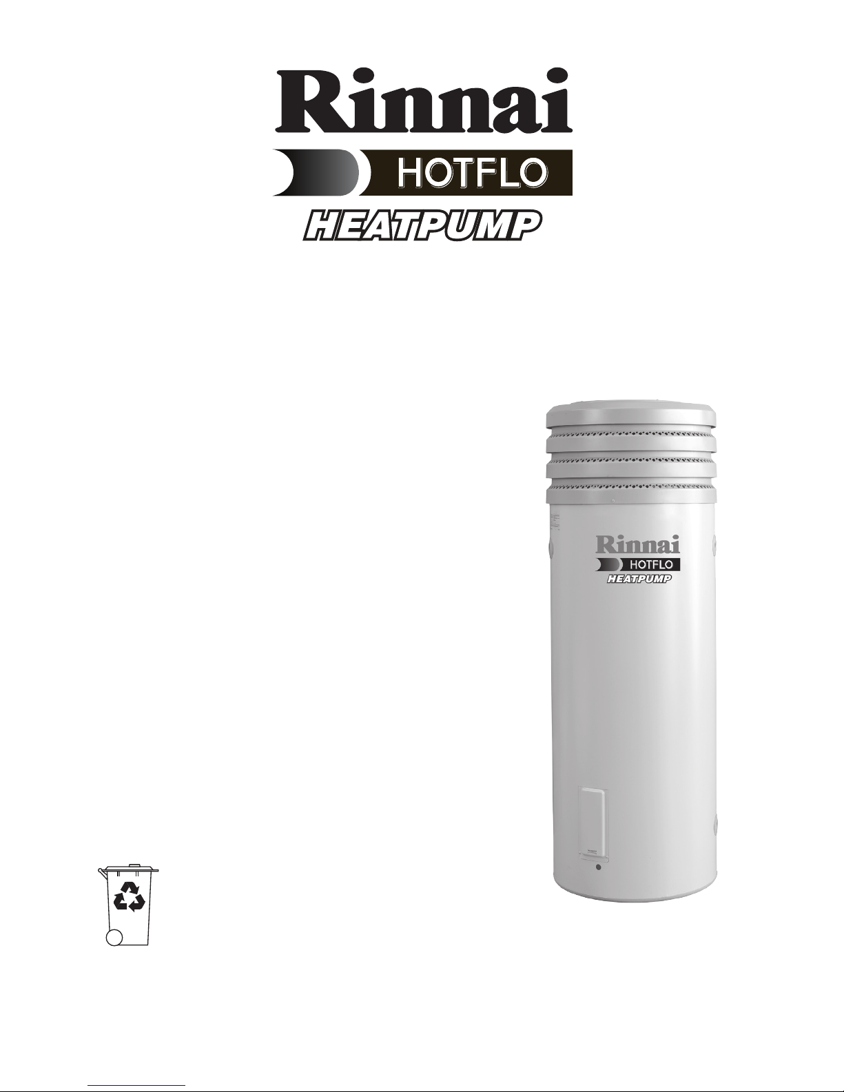
Rinnai RIN250EHP Installation And Owner's Manual
Installation and Owner’s Manual
Model: RIN250EHP
H4123 025961 Rev. A July 2012
Electric Heat Pump
Specications and materials may change without notice.
Effective for Heat Pump water heaters manufactured and sold after 1st May 2011.
Carefully remove all packaging and
transit protection from the heater before
installation. Dispose of the packaging
responsibly using re-cycling facilities
where they exist.
Installation Details
Owner’s Information
Warranty
For advice, repairs and service, call:
1300 555 545

H4123 025961 Rev. A July 2012
Installation and Owner’s Manual – Heat Pump
Rough-In Diagram 2
Installation Instructions 3
Installation Declaration 12
Owner’s Manual 13
Troubleshooting 19
System Maintenance 21
Safety Information 22
Warranty 23
Contents

1
H4123 025961 Rev. A July 2012
Installation and Owner’s Manual – Heat Pump
About the Rinnai Heat Pump
The Rinnai Heat pump is a very efcient
water heater that can signicantly
reduce energy consumption as
compared to an electric storage system.
The principle of its operation is very
similar to the operation of a refrigerator,
but in reverse. There is latent heat
energy in the air and this is transferred
to the heating system and the water.
The warmer the climate in which it is
installed, the more efcient the heat
pump system will be at heating water.
Heat Pump Installation
While heat pumps work best in warmer
climates, they will continue to work in
cooler areas.
The map below shows the cooler areas
of Australia shaded in gray.
In these cooler areas, consumers may
experience longer hot water heat-up
times in winter. Because the efciency
benets of heat pumps in these
conditions is reduced compared to
other hot water systems, installation
of heat pumps in these areas is not
recommended.
Perth
Melbourne
Heat pumps not recommended in these areas
Hobart
Darwin
Brisbane
Sydney
Adelaide
Based on average winter temperature figures from the Bureau of Meteorology
For further information, see http://www.bom.gov.au
Canberra
2
H4123 025961 Rev. A July 2012
Installation and Owner’s Manual – Heat Pump
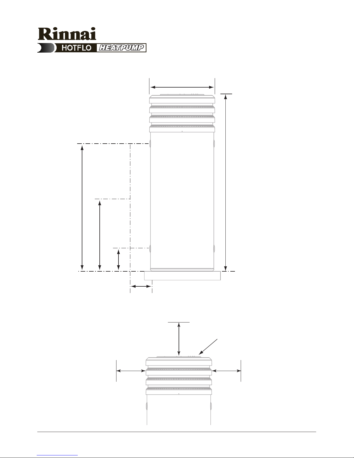
Rough-In Diagram
100
632
1711
508
195
Hot
Cold
Tempering
Valve
700
150
150
Allow 700 mm clearance
above and 150mm
clearance to either side
of the unit
Allow 50% of the height of the
water heater for clearance
above to replace the anodes
Net weight = 107kg
Model E2FHG4HWOC shown

3
H4123 025961 Rev. A July 2012
Installation and Owner’s Manual – Heat Pump
Regulatory Requirements
This water heater must be installed
by a licensed tradesperson, and in
accordance with:
• AS/NZS3500.4.2 “National
Plumbing and Drainage Code Hot
Water Supply Systems – Acceptable
Solutions”.
• AS/NZS3000.
• Local authority regulations.
• Outside Australia and New Zealand,
please refer to local plumbing and
building codes and regulations.
• Notice to Victorian customers from
the Victorian Plumbing Industry
Commission – this water heater must
be installed by a licensed person as
required by the Victorian Building Act
(1993). Only a licensed person will give
you a compliance certicate, showing
that the work complies with all the
relevant Standards and only a licensed
person will have insurance protecting
their workmanship for 6 years.
Note: This water heater and
heat pump components are
not suitable for pool heating.
Specications
The net weight of the heat pump is
107kg.
Dimensions are shown in the rough in
diagram in this manual.
Installation Instructions
4
H4123 025961 Rev. A July 2012
Installation and Owner’s Manual – Heat Pump
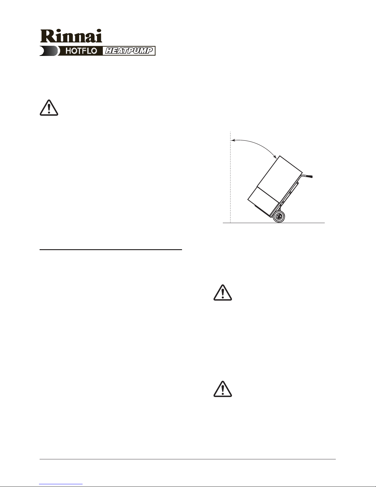
Transport and Handling
Critical: When moving the unit,
it must be close to vertical at
all times.
When using a trolley to move
the unit, ensure it is not
tilted more than 45° from the
vertical.
Non-compliance will void
warranty and severely affect
product performance and
operation.
Step 1
• Arrive at site and conduct a safety
audit.
• Safety audits can also be known as
Work Method Statements (WMS) or
Job Site Analysis (JSA).
• Park your vehicle as close as
allowable to your installation.
• Unload all materials in a safe manner.
• Position all materials in a convenient
position near the work area.
• The existing tank (if applicable)
should be drained and removed in a
responsible manner.
Never tilt unit more than
45˚ from vertical
Installation Instructions
Note: Do not commence
a job where the risks
cannot be controlled.
Note: Do not drain on to
grass or garden beds.
5
H4123 025961 Rev. A July 2012
Installation and Owner’s Manual – Heat Pump
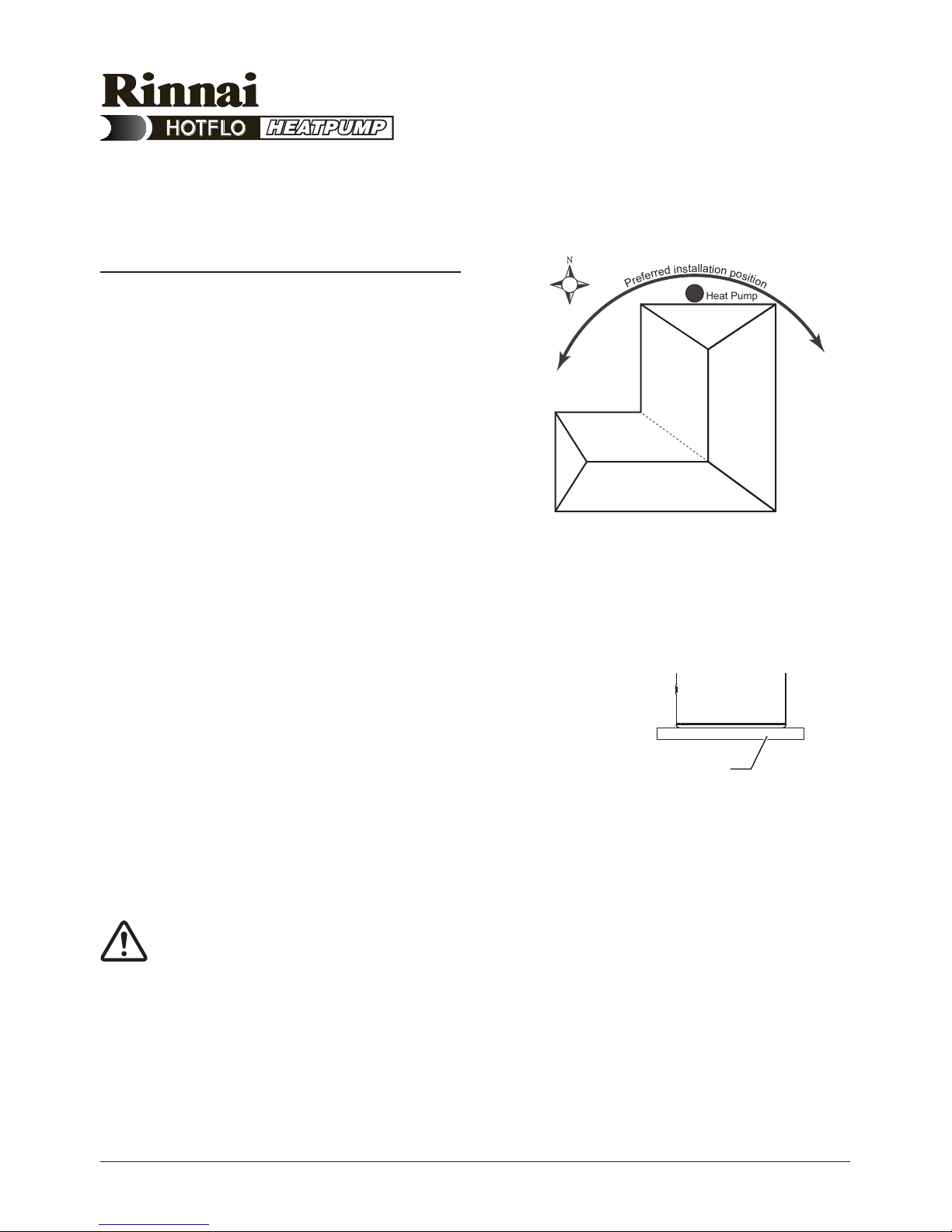
Placement of New Tank
Step 2
• The water heater must be installed
outdoors, close to the most
frequently used hot water outlet.
• Optimum installation location is on
the warmest side of house.
• The location must consider noise
impact on living areas. Avoid
positioning near bedrooms or
neighbours’ bedrooms. Although the
running noise level is very low (51
dB(A)) it can be expected that the
heat pump will run during the night.
• Adequate access must be available
to the relief valve and anodes.
• Safely position the new unit on a
level surface in accordance with all
plumbing and building regulations.
• A properly drained overow tray
must be used where property
damage could occur from water
spillage. (See AS/NZS3500.4.2 for
further details.)
Note: The warranty does not
cover consequential damage
due to leakage of the water
heater.
Installation Instructions
Heat Pump
P
r
e
f
e
r
r
e
d
i
n
s
t
a
l
l
a
t
i
o
n
p
o
s
i
t
i
o
n
Install a plinth under the
water heater where the
water heater is subjected
to wet conditions
6
H4123 025961 Rev. A July 2012
Installation and Owner’s Manual – Heat Pump
• Allow 200m3 of free space
surrounding the unit. This provides
clear ambient airow assisting the
product’s performance.
• The area must also be clear of debris
such as leaves and tree branches.
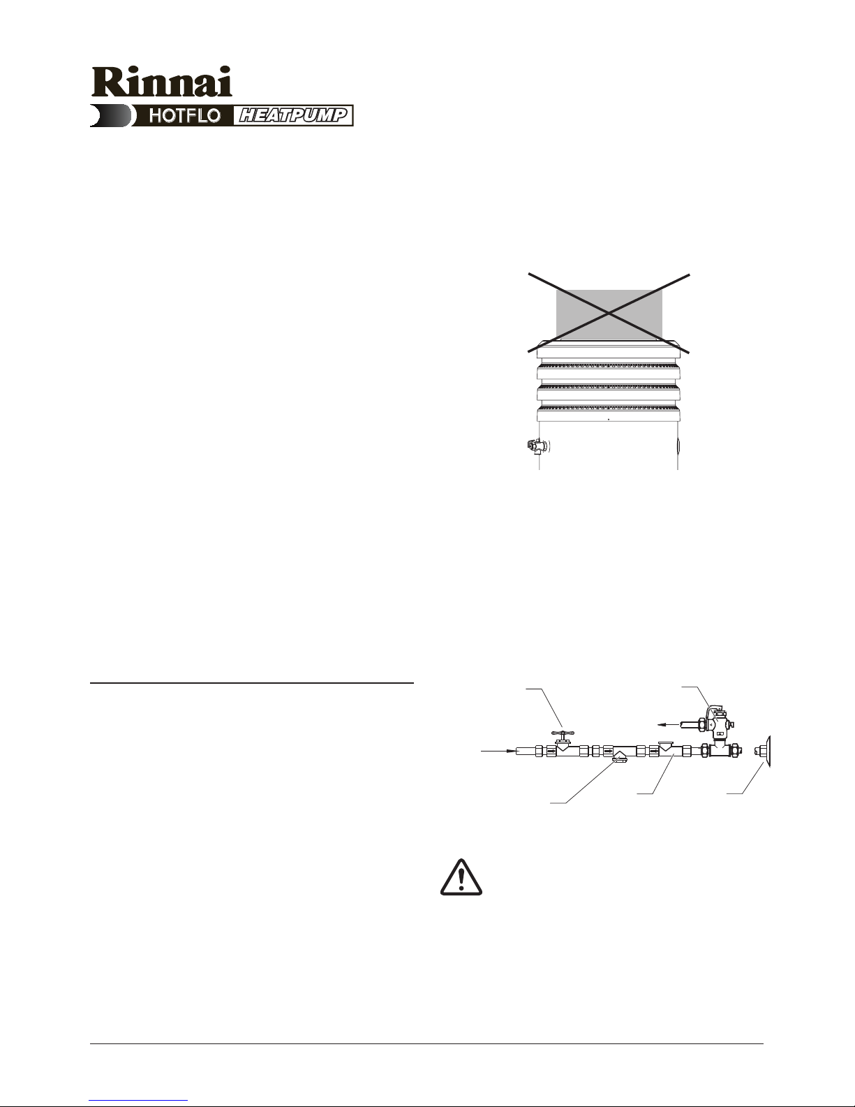
• Allow 700 mm clearance above and
150mm clearance to either side of
the unit as shown in the Rough-In
Diagram on page <?>.
• Ensure there are no obstructions
placed on top of the unit.
• Total clearance required from ground
to install unit is approximately
2410mm.
Plumbing Connections
Step 3
• Refer to the Rough-In Diagram on
page <?> for detailed information on
position of plumbing.
• An approved isolating valve, non-
return valve, line strainer (optional
but recommended), and union must
be tted between the supply main
and the RP¾/20 socket in the water
heater.
• All ttings must be approved by the
relevant installation Authority.
Installation Instructions
Drain
Union
Connection
Non-return
Valve
Line
Strainer
Cold Water
Inlet
Isolating Valve
(Spindle Vertical)
Cold water expansion
control valve
Note: For S.A. and W.A., it
is a state requirement that
a cold water expansion
control valve be tted on
the cold water supply line
between the non-return
valve and the water heater.
7
H4123 025961 Rev. A July 2012
Installation and Owner’s Manual – Heat Pump
• This water heater is designed for
direct connection to water supply
pressures of no greater than 800kPa.
• Where the mains pressure can
exceed or uctuate beyond 800kPa,
a pressure limiting device (complying
with AS1357) must be tted.
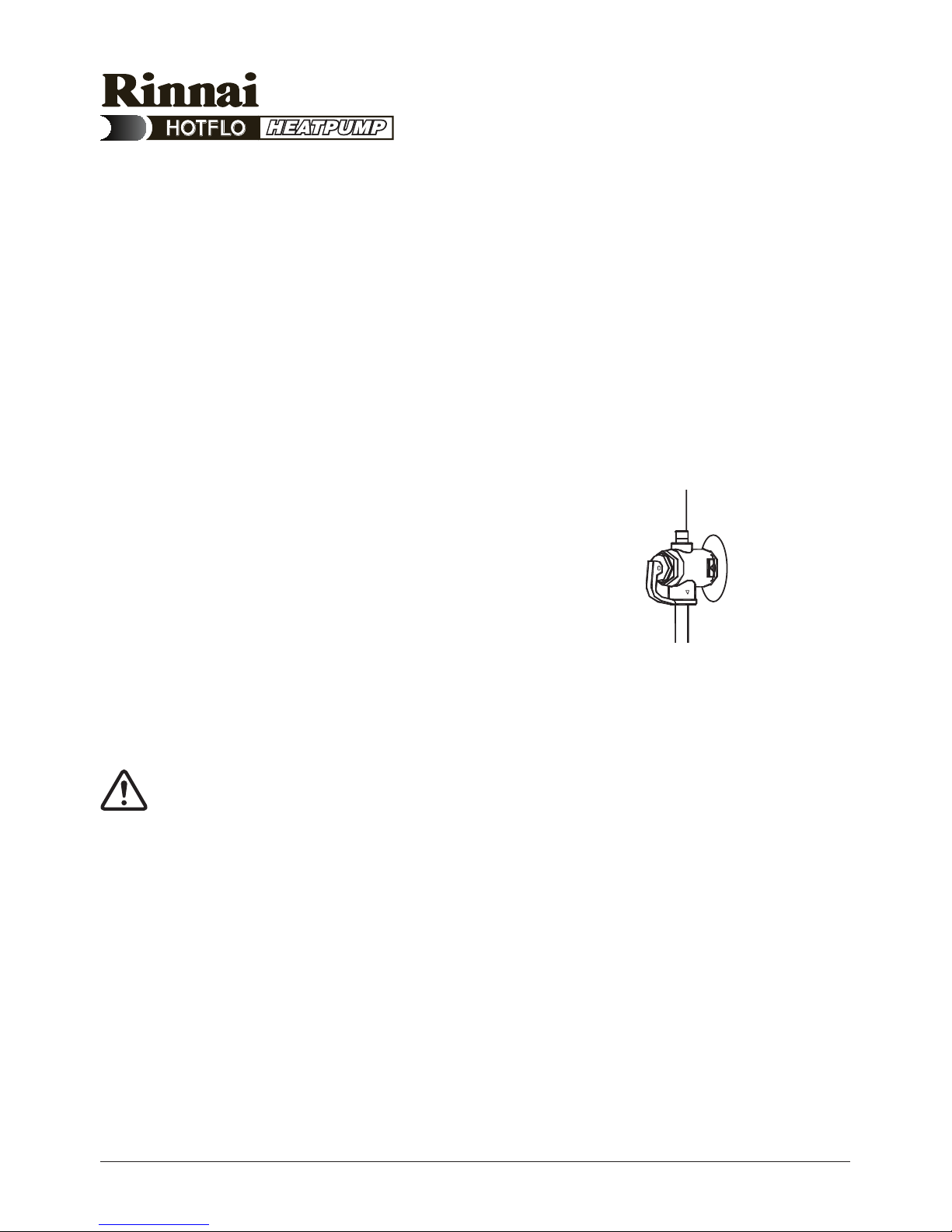
PTR Valve
• Connect the supplied PTR valve
into the top socket marked “RELIEF
VALVE” and discharge according to
plumbing regulations.
• PTR Valves for the unit
are rated at
1000kpa.
• The drain line from this valve must
run in a continuously downward
direction with the discharge end left
permanently open to atmosphere.
Warning: A separate drain
line must be run for this relief
valve. It is not permitted to
couple drain lines from relief
valves into a single common
drain line.
• The PTR Valve is not intended to
enable connection of the water
heater to supplementary energy
sources such as solar panels or
slow combustion stoves (refer AS/
NZS 3500.4.2 for guidance on these
types of installations)
Installation Instructions
 Loading...