

Rinnai RIB2312L, RIB2312N Operation & Installation Manual
This appliance shall be installed in accordance with:
• Manufacturer’s Installation Instructions
• Current AS/NZS 5601 AS/NZS 3000
• Local Regulations and Municipal Building Codes including local OH&S requirements
This appliance must be installed, maintained and removed only by an Authorised Person.
For continued safety of this appliance it must be installed and maintained in
accordance with the manufacturers instructions.
All Rinnai gas products
are A.G.A. certified.
SAPPHIRE GAS LOG FLAME FIRE
Operation / Installation Manual
MODELS: RIB2312N & RIB2312L

Congratulations on the purchase of your Rinnai Sapphire gas log flamefire.
We trust you will have many years of comfort and enjoyment from your appliance.
BEFORE PROCEEDING WITH THE OPERATION OR INSTALLATION OF YOUR NEW HEATER
PLEASE READ THIS MANUAL THOROUGHLY AND GAIN A FULL UNDERSTANDING OF THE
REQUIREMENTS, FEATURES AND OPERATION OF YOUR NEW APPLIANCE.
Rinnai 2 SAPPHIRE RIB2312 OIM

TABLE OF CONTENTS - OPERATION
BEFORE YOU START ................................................ .. ......................... .. .......................... .. .......4
INSTALLATION REQUIREMENTS..................................................................................................................... 4
CERTIFICATION................................................................................................................................................. 4
CARTON CONTENTS / ITEM CHECKLIST........................................................................................................ 4
INSTALLATION RECORD ..........................................................................................................6
SAFETY .....................................................................................................................................7
SAFETY DEVICES.............................................................................................................................................. 9
ABOUT YOUR HEATER ...........................................................................................................10
GENERAL DESCRIPTION................................................................................................................................ 10
DESIGN FEATURES................. ... ... .... ... ... ... ....................................... ... .... ... ... ................................................. 11
CONTROL PANEL OPERATION ...............................................................................................12
TO TURN YOUR HEATER ON ......................................................................................................................... 12
TO TURN YOUR HEATER OFF ....................................................................................................................... 12
INTERRUPTION TO ELECTRICITY OR GAS SUPPLY DURING OPERATION.............................................. 12
RESTART PROCEDURE AFTER INTERRUPTION TO ELECTRICITY SUPPLY ........................................... 12
FULL CONTROL AND PARTIAL CONTROL.................................................................................................... 12
REMOTE CONTROL OPERATION .............................. .. ......................... .. .......................... .. .....13
BATTERIES AND ACTIVATING THE REMOTE CONTROL ........ ... ... ... ....... ... ... ... .... ... ... ... .... ... ... ... ... .... ... ... ... . 13
BUTTON FUNCTIONS, DISPLAY & OPERATION...........................................................................................13
REPLACING THE CR2450 BUTTON BATTERIES............. ... ... .... ...... ... .... ... ... ... ... .... ... ... ... .... ... ... ... ... .... ...... ....14
LOST, MISPLACED OR BROKEN REMOTE CONTROL... ... ... .... ... ... ... ....................................... ... ... .... ... ....... 14
CARE AND MAINTENANCE .....................................................................................................15
SERVICE........................................................................................................................................................... 15
TROUBLE SHOOTING ..................................................................................................................................... 15
ERROR CODES..................... ... ... ... .... ... ....................................... ... ... ... .... ....................................................... 16
TROUBLE SHOOTING CHECKLIST ................................................................................................................ 17
ABNORMAL FLAME PATTERN........................................................................................................................ 17
TABLE OF CONTENTS - INSTALLATION ................................................................................18
CONTACT INFORMATION .......................................................................................................52
Rinnai 3 SAPPHIRE RIB2312 OIM
BEFORE YOU START
IMPORTANT
12
6
11
7
8
9
1
4
5
2
3
5
5
A
10
10
4
2
3
A. Standard
Fascia
B. Classic
Fascia *
13
A
12345
678
91011
12
13
INSTALLATION REQUIREMENTS
This heater must be installed only by an authorised person. The installation must conform to local regulations.
The installation must also comply with the instructions supplied by Rinnai.
Service and removal must be carried out only by an aut ho ris ed perso n.
CERTIFICATION
®
The Rinnai Sapphire
The AGA Certification Number is shown on the appliance dataplate.
No parts or functions should be modified or permanently removed from the heater.
Please keep these instructions in a safe place for future reference.
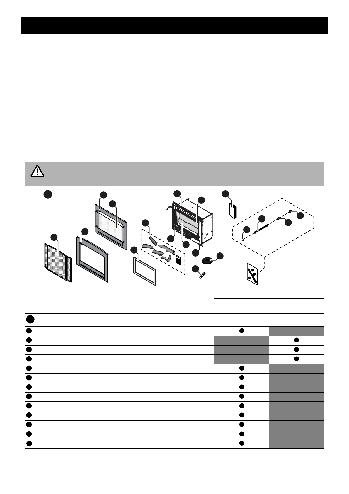
CARTON CONTENTS / ITEM CHECKLIST
The components for Sapphire heater are supplied in separate cartons, the following tables list which components
are in each carton. Ensure that the components listed for the installation meth od being installed are presen t before
proceeding with the installation.
The Engine and Fascia are packed into two separate cartons and are required for all installation
types. Masonry installations may require a flexiliner flue to be installed, refer to “FLUEING” on
page 26 for details.
has been certified by the Australian Gas Association.
Component Descriptions
* The Classic fascia / Mesh dress guard is suitable for Masonry and Zero Clearance - Inbuilt Installat ion ONLY!
It can NOT be used on a Console or Plinth installation.
Carton Contents
Engine Fascia
Engine and Fascia - Masonry Installations (x2 Cartons)
Rinnai Sapphire Engine.
A. Fascia (Standard Model) / B. Fascia (Classic Model)*.
A. Glass dress guard (Standard Model) / B. Mesh dress guard (Classic Model)*.
Inner metal surround.
Artificial log set / burn media, Satchel burner granules (shipped inside engine).
Semi rigid stainless steel gas pipe with 5/8” connections (x1).
½” BSP - 5/8” UNF flared brass adaptors (x1).
½” BSP Flared nut (x1).
5/8” UNF Plug (x1).
Fascia attachment screws (2 x 8g black, pre-fitted in tabs of heater engine).
Adhesive backed foam sealing strip.
Operation and Installation manual.
Remote Control Infra Red (IR)
Rinnai 4 SAPPHIRE RIB2312 OIM
BEFORE YOU START
A
3
7
2
1a+b
8
5
6
4
B
6
C
1a+b
A
3
2
7
4
5
6
1a+b
1a+b
D
A
3
2
4
5
6
7
8
3
E
Note: Standard model fascia shown for illustrative purposes
B
A
1
a
b
2
34567
8
C
A
1
a
b
23456
7DA
1
a
b
2345678
E
1
a
b
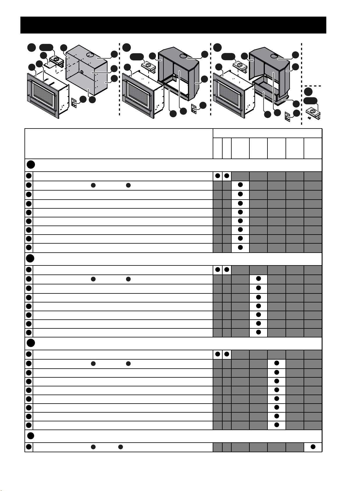
Component Descriptions
* The Classic fascia / Mesh dress guard is suitable for Masonry and Zero Clearance - Inbuilt Installat ion ONLY!
It can NOT be used on a Console or Plinth installation.
Zero Clearance - Inbuilt Installation (x3 Cartons)
See Engine and Fascia (Masonry Installations) contents on previous page.
Two piece Spigot Adaptor Top Half and Bottom Half.
Spigot guide panel.
Spigot guide rails (x2).
Zero Clearance - Top panel.
Zero Clearance - Rear panel.
Zero Clearance - Left and Right side panels.
Base panel.
Packet assembly screws (x27), grommets (x2) and rivets (x2).
Console Installation - Freestanding Installation (x3 Cartons)
See Engine and Fascia (Masonry Installations) contents on previous page.
Two piece Spigot Adaptor Top Half and Bottom Half.
Console Installation - Top panel.
Console Installation - Left side panel.
Console Installation - Right side panel.
Console Installation - Rear panel.
Console Installation - Pillar.
Packet assembly screws 35 x 8g and 7 x M5.
Carton Contents
Box
Engine
Console
Clearance
Zero
Fascia
Plinth
Remote
Control
Spigot
Adaptor
Plinth Installation - Freestanding Installation (x3 Cartons)
See Engine and Fascia (Masonry Installations) contents on previous page.
Two piece Spigot Adaptor Top Half and Bottom Half.
Plinth Installation - Top panel.
Plinth Installation - Left side panel.
Plinth Installation - Right side panel.
Plinth Installation - Rear panel.
Plinth Installation - Pillar assembly.
Plinth Installation - Base panel.
Packet assembly screws 35 x 8g (only 29 needed for installation) and 7 x M5.
Optional Two Piece Spigot Adaptor (x1 Carton)
Two piece Spigot Adaptor Top Half, Bottom Half and assembly screws (x4)
Rinnai 5 SAPPHIRE RIB2312 OIM

INSTALLATION RECORD
WARNING
WARNING
WARNING
WARNING
INSTALLERS / GAS FITTERS DETAILS
Installers Name: ____________________________________________________________________
Company Name: ____________________________________________________________________
Company Address: ____________________________________________________________________
____________________________________________________________________
____________________________________________________________________
Company Contact Details
Telephone: ____________________________________________________________________
Mobile Phone: ____________________________________________________________________
Certificate of Compliance / Certification Number: _____________________________________________
Authorised Persons - Licence Number: ____________________________________________________
Installers Signature: ____________________________________________________________________
Installation Date: ____________________________________________________________________
APPLIANCE DETAILS
Model Number: ____________________________________________________________________
Serial Number: ____________________________________________________________________
Installation Address: ____________________________________________________________________
____________________________________________________________________
____________________________________________________________________
____________________________________________________________________
THIS APPLIANCE MUST BE INSTALLED, SERVICED
AND REPAIRED ONLY BY AN AUTHORISED PERSON.
The glass dress guard supplied with this appliance must not be
permanently removed as it fulfils an operational safety function.
Additional dress guards including free standing types may be
used in conjunction with, but not replace, the dress guard
supplied with this appliance.
Rinnai 6 SAPPHIRE RIB2312 OIM
SAFETY
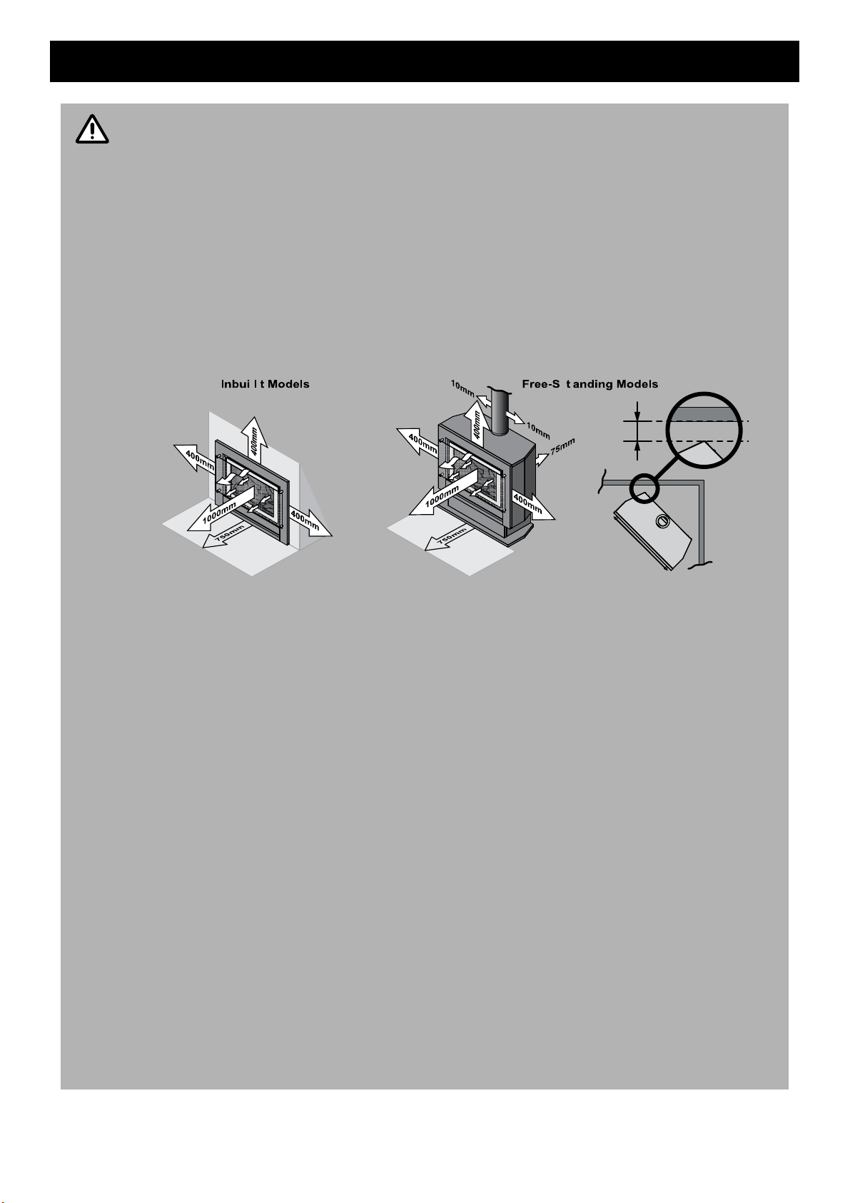
WARNING
75mm
Note: Standard model
fascia shown for
illustrative purposes
• Failure to comply with these instructions could result in a fire or explosion, which could cause
serious injury, death or property damage.
• Improper installation, adjustments, service or maintenance can cause serious injury, death or
property damage. Such work must be performed only by an authorised person.
• The appliance must be installed in accordance with the local gas and electrical authority
regulations.
• Flue terminal must always vent directly to outdoors.
• DO NOT extend the flue vertically or horizontally in ways other than prescribed in the appliance
manufacturers’ installation instructions.
• For information on gas consumption, see data plate on the appliance.
• This appliance must not be instal led wh ere cu rtains or other combustible materials could come
into contact with it. In some cases curtains may need restraining.
• WARNING: This heater MUST NOT be used if either of the glass panels are damaged.
• When considering installation ensure minimum clearances as follows are adhered to:
• Heat radiating from the front of this heat er may over time affect the appeara nce of some materials
used for flooring such as carpet, vinyl, cork or timber. This effect may be amplified if the air in
the room contains cooking vapours or cigarette smoke. To avoid this possibility, it is
recommended that a mat or similar protectiv e sheet be placed in front of the appliance, extending
at least 750 mm in front of the dress guard.
• This appliance is not intended for use by persons (including children) with reduced physical,
sensory or mental capabilities or lack of expe rience and knowledge, unless they have been given
supervision or instruction concerning use of the appliance by a person responsible for their
safety.
• The appliance is not intended for use by young children or infirm persons without supervision.
• Young Children must be supervised when in the vicinity of this heater while it is in operation.
• The Dress Guard MUST be fitted to this appliance to reduce the risk injury from serious burns
and no part of it should be permanently removed.
• For protection of young children or the infirm a secondary gu ard is required.
• If the supply cord is damaged or requires replacing, it must be replaced by the manufacturer or
the manufacturer's agent or similarly qualified person in order to avoid a hazard.
• The heater must not be located immediately below a power socket outlet.
• Not to be connected to a LP Gas Cylinder located Indoors.
• A dedicated 230 V earthed 10 Amp power point must be used with this appliance.
• DO NOT modify this appliance. Modifying from original specifications may create a dangerous
situation and will void your warranty.
• Only the flue components specified by Rinnai must be used.
• Unpack the heater and check for damage. DO NOT INSTALL A DAMAGED HEAT ER. If t he hea te r
is damaged, contact your supplier for advice.
• Before installing the heater, check the label for the correct gas type (refer rating plate, inside the
appliance).
• Refer to local gas authority for confirmation of the gas type if you are in doubt.
Rinnai 7 SAPPHIRE RIB2312 OIM
SAFETY
Note: Standard model fascia shown for illustrative purposes
Note: Standard model fascia shown for illustrative purposes
Note: Standard model fascia shown for illustrative purposes
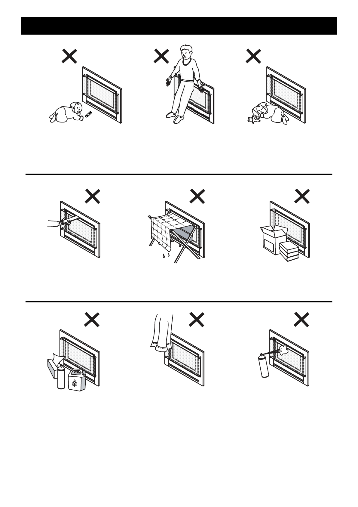
The appliance is not intended for use by young children or infirm persons without supervision.Young children
should always be supervised to ensure that they DO NOT play with the appliance.
DO NOT sit or lean against the heater.
DO NOT allow children or elderly persons to sleep in the warm air discharge from the heater.
DO NOT post or allow children to post articles into the louvres of the heater.
DO NOT cover or place articles on this heater.
DO NOT place articles in front of the louvres.
DO NOT operate / install this heater in ar eas where painting is taking place, or in places such as hairdressing
salons, where there may be fluff and dust, and where aerosols are used.
DO NOT place articles on or against this appliance.
DO NOT use or store flammable materials in or near this appliance. Keep flammable materials away from heater.
Combustible materials MUST NOT be placed where the heater could ignite them.
DO NOT spray aerosols in the vicinity of this appliance while it is in operation. Most aerosols contain flammable
substances which can be a heater hazard if used near this heater when it is in use.
Rinnai 8 SAPPHIRE RIB2312 OIM
SAFETY
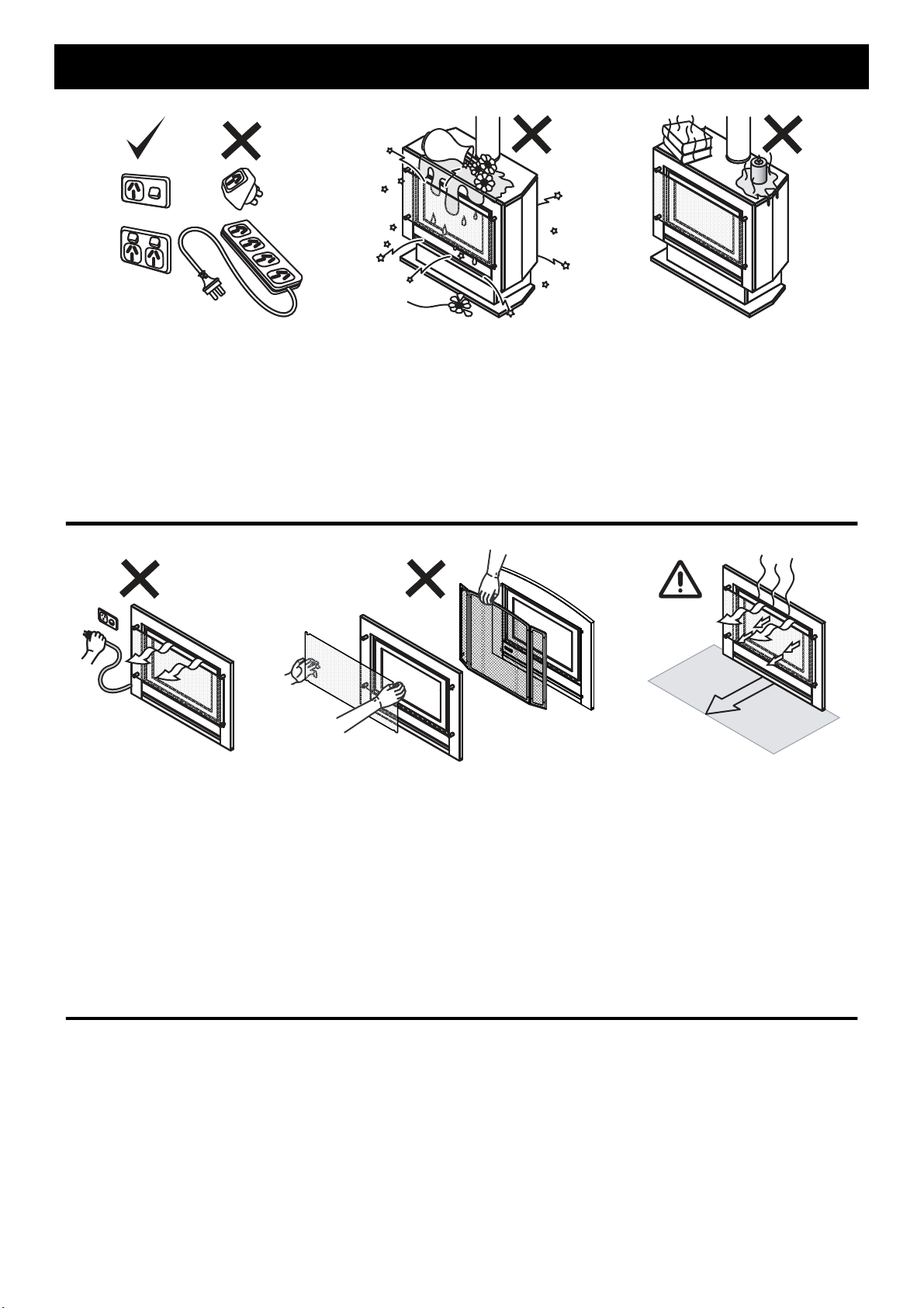
A dedicated 230V earthed 10 Amp power point must be used with this appliance.
DO NOT use power boards or double adaptors to operate this appliance. Th e heater MUST NOT be lo cated below
a power socket-outlet.
DO NOT place containers of liquid on top of the heater. Water spillage can cause extensive damage to the
appliance and create an electrocution hazard.
DO NOT place articles on or against this appliance.
DO NOT CONNECT TO AN LPG GAS CYLINDER INDOORS.
750mm
Turn the heater ‘OFF’ after use.
DO NOT unplug the heater while it is in operation or while the fan is still cycling.
DO NOT remove the Dress Guard. The dress guard is fitted to this appliance to reduce the risk of fire o r injury from
burns and no part of it should be perman ently remove d. For protection of children or the infirm, a secondar y guard
is recommended.
Heat emanating from the front of the appliance may over time affect the appearance of some materials used for
flooring such as carpet, vinyl, cork or timber. This affect may be amplified if the air in the room contains cooking
vapours or cigarette smoke. To avoid this possibility, it is recommended that a mat be placed in front of the
appliance, extending at least 750 mm in front of the heater.
When the heater is operated for the first time or after long periods of no n use a sli ght odour may be emitted, this is
normal. However if odours persist switch ‘OFF’ the appliance and contact Rinnai.
SAFETY DEVICES
Over Heat Switches: When the heater gets too hot during operation (for example when air outlet louvres are
blocked) these devices turn the gas off automatically and allow the heater to restart when cooled down.
Electrical Fuse: The electrical circuits are protected by a fuse.
Flame Failure Sensing System: This device automatically cuts off the gas supply to the heater in the event of a
flame failure.
Power Failure: In the event of a power failure or power cut, the gas valves will automatically close.
Rinnai 9 SAPPHIRE RIB2312 OIM
ABOUT YOUR HEATER
Note: Standard model
fascia shown for
illustrative purposes.
The Classic model
fascia is only
available for inbuilt or
masonry installations
GENERAL DESCRIPTION
Your Sapphire is a burning log effect, gas space heating appliance with natural draft comb ustion system, intended
for use with Natural Gas, Propane and ULPG. The Bur ning log effect is achieved using one single main burner with
strategically placed, 'life like', imitation logs and granules. Temperature control is achieved by pressing the up or
down marked arrows on the manual control switch or via a cordless wall mounted remote control.
This heater has an electronic ignition with intermittent pilot. The pilot is only on when the heater is in operation.
Burner, logs and granules are contained in a glass fronted, sealed burne r box.
Combustion air is drawn from the room. Combustion product is exhausted via the flue discharge vent when
installed in a masonry chimney or when installed in a zero clearance box or as a stand alone unit through a
100mmØ x 150mmØ twin skinned flue to the outside of the house.
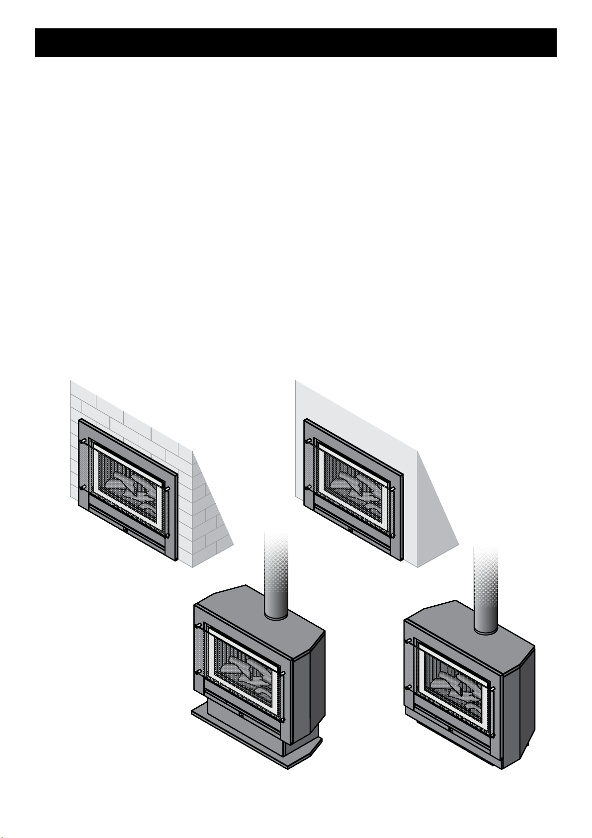
This appliance is modular and primarily consists of an 'Engine' that is utilized in any of the 3 configuration types as
listed below.
1. Fireplace / Masonry installation - Engine:
The appliance is directly mounted into an existing masonry fire place or a non- combustible/mason ry enclosure
that has a chimney. When installed correctly the appliance is a flush to wall mount.
2. Zero Clearance installation:
The Appliance is fitted within a sheet metal Zero Clearance Box Assembly that has been installed into a wall or
other suitable structure. Materials need not be non-combustible. When installed correctly the appliance is a
flush to wall mount.
3. Freestanding Plinth or Console appliance:
The appliance is housed in a decorative fabricated sheet metal box that is in tende d to be freestanding and not
inbuilt.
ZERO CLEARANCE
MASONRY
Rinnai 10 SAPPHIRE RIB2312 OIM
PLINTH
CONSOLE
DESIGN FEATURES
1a
7
3
4
5
1b
4
5
a
b
8
c
d
e
2
6
9
7
3
7
7
2
2
10
6
9
10
1a
1b
2
ab3
4
567
8cde9
10
ABOUT YOUR HEATER
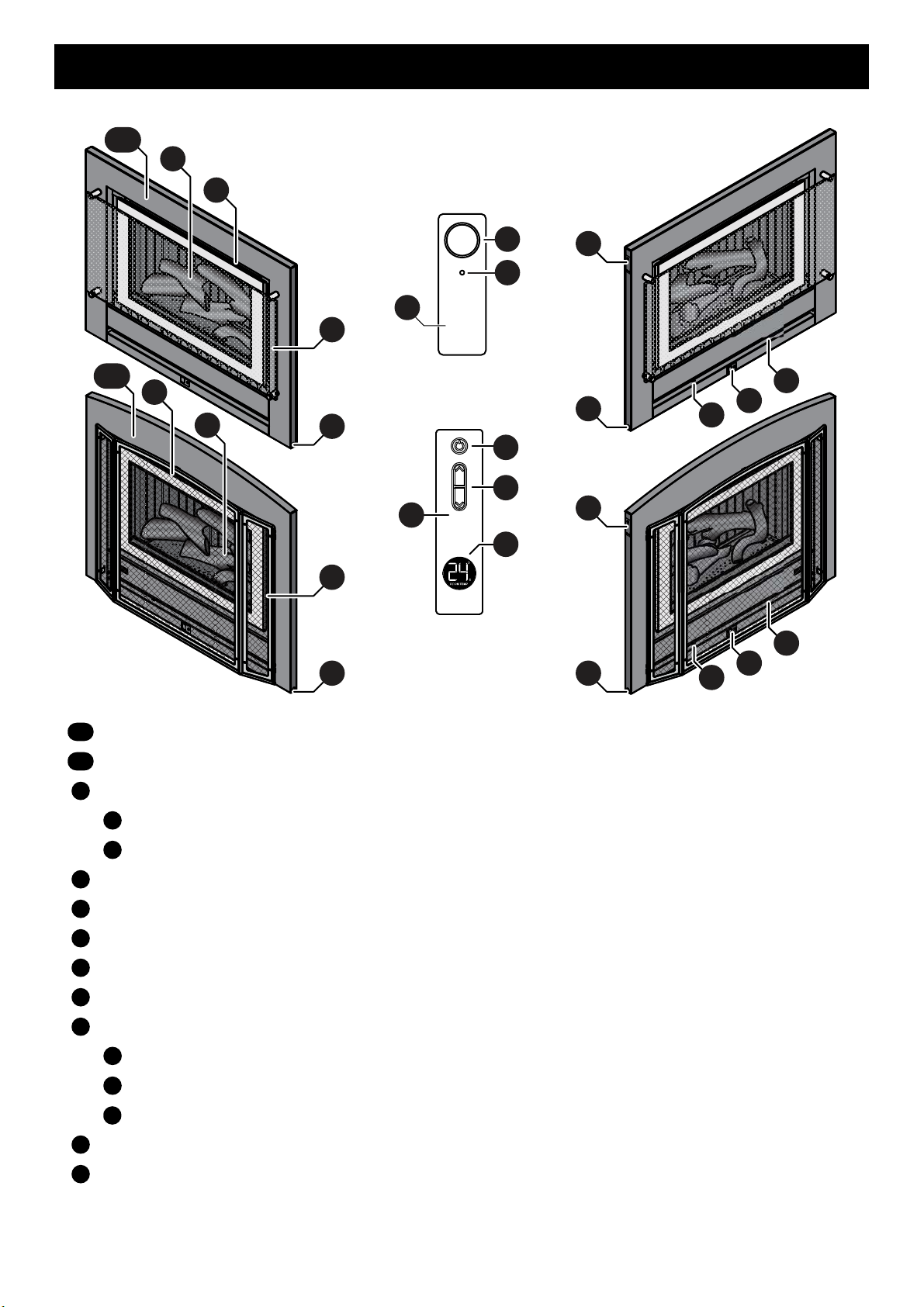
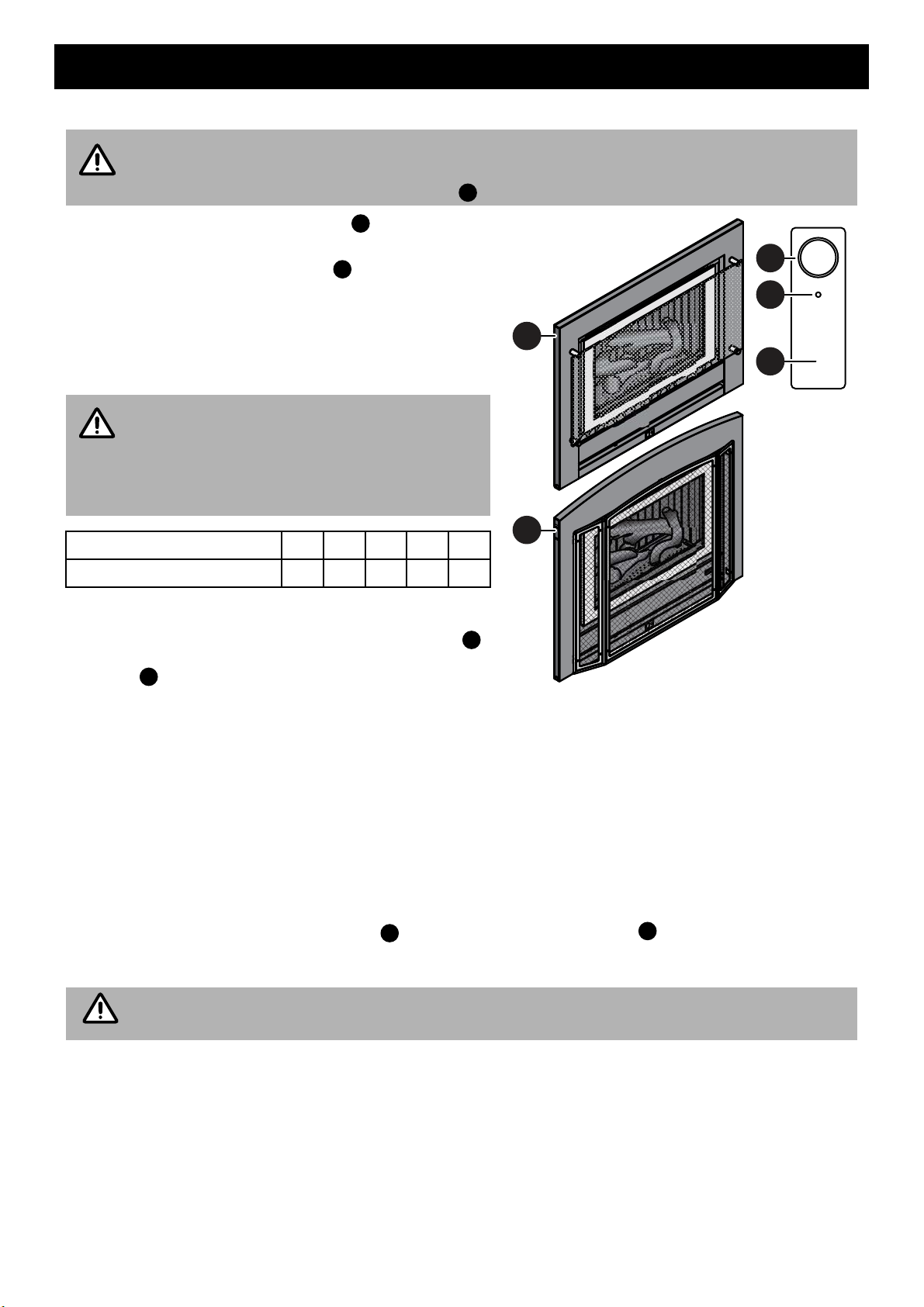
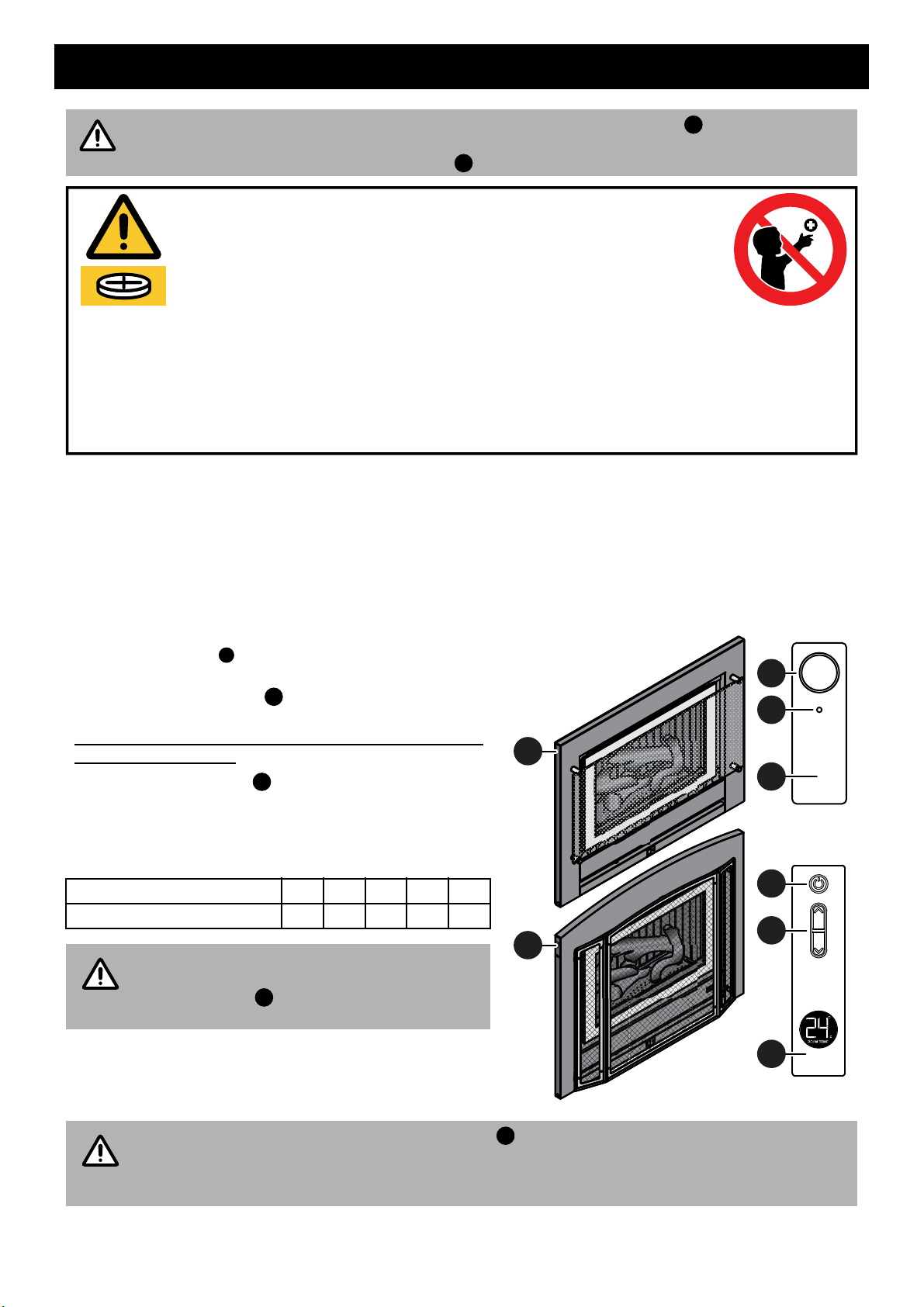
Rinnai Sapphire Heater - Standard fascia model
Rinnai Sapphire Heater - Classic fascia model (Masonry and Inbuilt installations only)
Appliance push button control panel
ON / OFF button
Standby Indicator (Red)
Glass dress guard (standard model) / Mesh dress guard (classic model)
Flame window - artificial log set and burn media
Warm air discharge vent
Return air vent
Alternative power cable outlet location on front panel can be left or right handed
Remote (IR) control
Standby / ON button
Flame Up / Down buttons
Room temperature display (displays the current temperatur e of the r oom in which the contr ol is locate d)
Remote (IR) control receiver window
Viewing window cut outs for error code display (This is located behind the fascia, see page 16 for details)
Rinnai 11 SAPPHIRE RIB2312 OIM
CONTROL PANEL OPERATION
NOTE
b
b
a
1
1
1
1
a
NOTE
aba
1
NOTE
TO TURN YOUR HEATER ON
BEFORE PROCEEDING ENSURE THE GAS AND ELECTRICITY ARE TURNED ON.
When the heater is in the OFF condition (the power supply connected and switched ON but the
heater turned OFF) the Red Power Indicator will be extinguished. This is normal.
Access the 'Push Button Control Panel' . This is located
on the top left hand side of the appliance.
Step 1. Press the ON / OFF button once. You will be
able to hear the ignition sparking.
Step 2. The sparking ignition stops when the pilot flame
has been established.
The main burner then ignites off the pilot flame and
is automatically preset to Stage 5 - High Flame.
FLAME HEIGHT AND FAN SPEED
The relationship between flame height and fan
speed is factory preset and ca nnot be ad ju st ed.
Refer to “REMOTE CONTROL OPERATION” on
the next page for Flame / Fan options.
Flame Height 12345
Fan Speed
TO TURN YOUR HEATER OFF
To turn the heater ‘OFF’ press the ‘ON’/’OFF’ button
once, when the heater is in the off state the Red Power
Indicator will be extinguished.
INTERRUPTION TO ELECTRICITY OR GAS SUPPLY DURING OPERATION
Interruption to the power or gas supply will turn your heater off and a restart will be required. This is a safety feature
designed to ensure that un-attended starts do not occur after power or gas interruptions.
RESTART PROCEDURE AFTER INTERRUPTION TO ELECTRICITY SUPPLY
To restart your heater once power has been restored follow the steps for “TO TURN YOUR HEATER ON” as
above.
FULL CONTROL AND PARTIAL CONTROL
Full operation of the heater is only possible by using the remote control. In the event of a mispla ced or broken
remote control or if the batteries for the remote control are flat, this appliance may still be operated in a limited
capacity by using the power ON/OFF button of the 'Push Button Control Panel' located on the top left hand
side of the appliance.
The heater will automatically modulate between flame settings to maintain the default set temperature of 22°C.
(2 speed only) Low Low Low High High
No control of the flame or heat output is possible via the appliance ON/OFF button.
Rinnai 12 SAPPHIRE RIB2312 OIM
REMOTE CONTROL OPERATION
IMPORTANT
a
b
Dispose of used button batteries immediately and safely. Flat batteries can still be dangerous and may be a choking hazard.
Inform others about the risk associated with button batteries and how to keep their children safe.
Remove the batteries if the remote is not going to be use for prolonged periods. This will help prevent damage from leaking
batteries. If leakage has occurred and corrosion is evident the remote will need to be replaced.
Leaking chemicals are toxic and MUST NOT be touched or ingested.
NEVER mix old and new batteries.
DO NOT immerse the remote control in any liquid, this will damage the remote control, rendering it inoperable and voiding
its warranty.
WARNING KEEP BATTERIES OUT OF REACH OF CHILDREN.
Swallowing may lead to serious injury in as little as 2 hours or death, due to chemical burns
and potential perforation of the oesophagus.
If you suspect your child has swallowed or inserted a button battery immediately call the
24-hour Poisons Information Centre on 13 11 26 for fast, expert advice.
Examine devices and make sure the battery compartment is correctly secured, e.g.
that the screws or other mechanical fasteners are tight. DO NOT use if compartment is not secure.
y
y
y
y
y
y
y
y
y
y
b
a
1
1
1
c
d
8
8
c
d
NOTE
d
NOTE
e
For the remote control to be able to function, the appliance ON/OFF button must be in the "ON"
position. Using the remote control to turn off the heater will place the heater into STANDBY mode,
when in this mode the Red Power Indicator will be on. This is normal.
BATTERIES AND ACTIVATING THE REMOTE CONTROL
• 2 x Button Batteries are supplied with the remote control.
• Remove th e plastic tab to activate.
• This remote control uses 2 x Lithium CR2450 or equivalent batteries.
• The appliance will flash and emit 'Beep s' to confirm the setting has been received from the remote control unit;
this indicates your remote control is now working.
BUTTON FUNCTIONS, DISPLAY & OPERATION
This remote control, selects flame height and fan speed
in five levels.
The ST ANDBY / ON button switches the heater between
the STANDBY and ON modes.
Flame height may only be adjusted after at least 30
seconds of operation.
The UP / DOWN buttons control the height of the flame
and heat output.
The relationship between flame height and fan speed is
factory preset and cannot be adjusted, there are five flame /
fan settings as listed below.
Flame Height 12345
Fan Speed
(2 speed only) Low Low Low High High
On initial start-up the appliance default flame
height setting is setting 5 - High. Use the UP /
DOWN buttons to control the height of the
flame / heat output.
The remote control temperature sensor (located base of the
controller) reads the temperature of where control is
currently located, this temperature reading is refreshed once
a minute.
Rinnai 13 SAPPHIRE RIB2312 OIM
The degrees Celsius room temperature display has a motion activated back light which will
remain illuminated for approximately 5 seconds after a movement is sensed or when a button is
pressed. Frequent illumination of the back light greatly reduces the remote controls operational
battery life, ensure that unnecessary illumination of the display is avoided.
REMOTE CONTROL OPERATION
f
g
g
h
j
i
j
i
f
Note: Remote contol is shown with back cover removed for illustrative purposes
g
h
ijh
i
1
b
a
1
1
1
NOTE
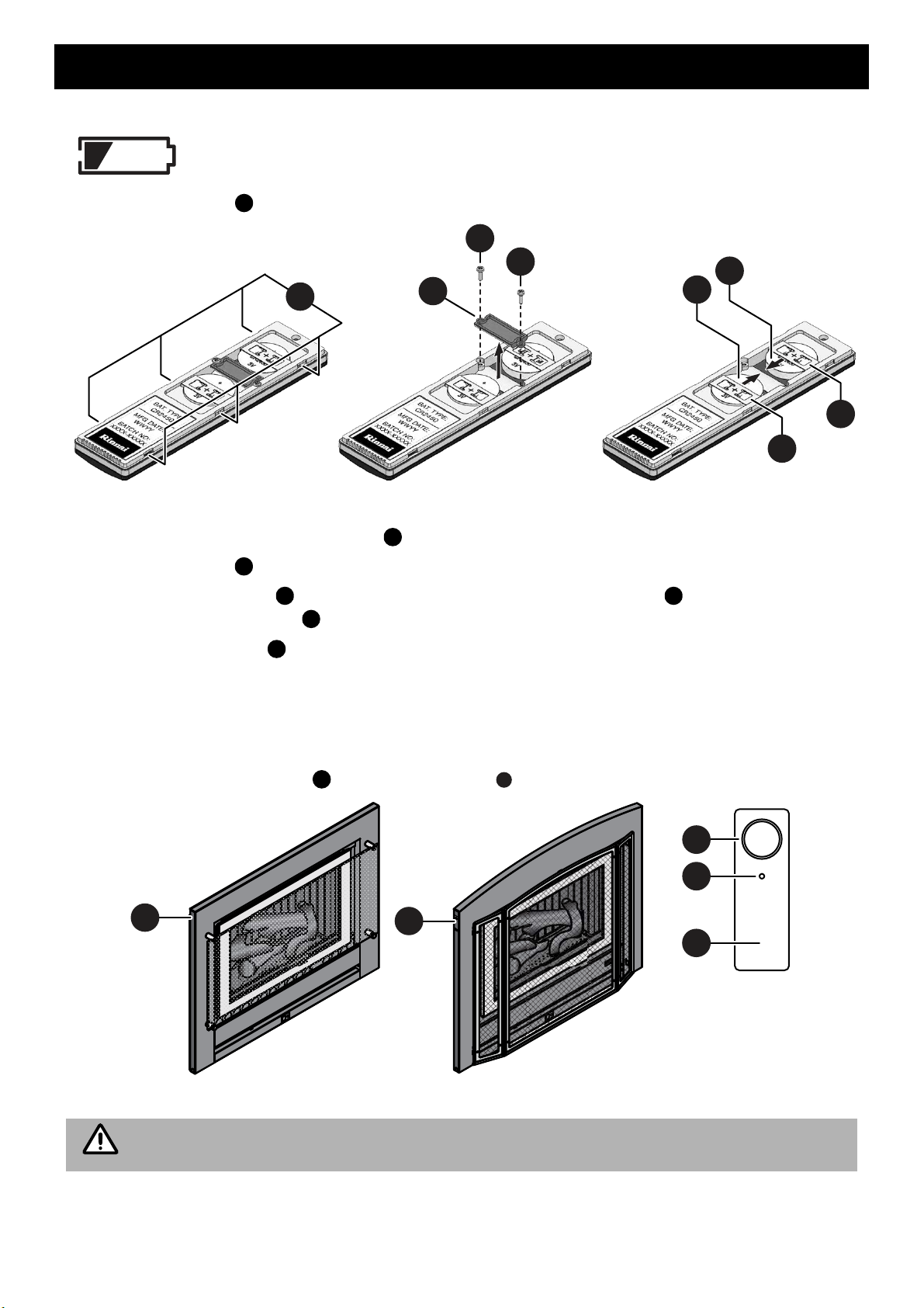
REPLACING THE CR2450 BUTTON BATTERIES
When this low power symbol appears the batteries are near to being fully discharged and are
unable to power the remote control properly. Replacement of batteries is now required.
1.Using a suitable lever remove the back cover by care fully pry i ng off the back cover at the 6 pr y
points .
2. Remove the two bridge retaining screws, using a small (No.0) Phillips head screw driver or equivalent.
3. Remove the bridge .
4. Remove the old batteries by carefully sliding them out from under the retainers , and into the space that
was created when the bridge was removed in step 3.
5. Insert two new batteries (CR2450), ensuring the positive “
6. Reassemble the bridge in reverse order as per steps 2 & 3 above.
7. Re-attach the rear cover by carefully clipping it back into place.
LOST, MISPLACED OR BROKEN REMOTE CONTROL
In the event of a lost, misplaced or broken remote control the appliance may still be operated in a limited capacity.
By using the manual control panel, power ON/OFF button , located on the top left hand side of the heater.
+ ” terminals are facing up.
a
The heater will automatically modulate between flame settings to maintain the default set temperature of 22°C.
No control of the flame or heat output is possible via the appliance ON/OFF button.
Rinnai 14 SAPPHIRE RIB2312 OIM
CARE AND MAINTENANCE
IMPORTANT
NOTE
NOTE
Your heater needs very little maintenance, but the following information will help you to keep it looking good and
working efficiently.
DO NOT attempt to clean the heater while the appliance is hot or operating.
All parts of the heater can be cleaned using a soft, damp cloth.
DO NOT use solvents or abrasives to clean any parts.
DO NOT spray aerosols in the vicinity of the heater whilst in operation.
DO NOT place articles on or against this heater.
DO NOT use or store flammable materials in or near this appliance.
SERVICE
Rinnai recommend that this appliance and installation be inspected and serviced every 2 yea rs or more frequently.
If the power supply cord or any other component of the heater are damaged, they must be replaced by Rinnai or
a suitably qualified person.
Any service or repair work should only be carried out only by an authorised person. Rinnai has service and spare
parts departments nationally. See back cover for contact details.
Service calls for general cleaning, maintenance and wear and tear are not necessarily covered
under the warranty. Service calls of this nature may be chargeable.
Faults caused by insufficient gas supply, gas quality, installation err ors or operation errors are not
covered by the Rinnai warranty. Refer to separate Warranty Booklet for details or go online at
www.rinnai.com.au//support-resources/warranty-registration/
TROUBLE SHOOTING
General Operation Characteristics
Before asking for a service call please check the following table as these characteristics are part
of the normal operation of the appliance and do not indicate a fault.
CHARACTERISTIC EXPLANATION
At ignition:
Warm air does not start when the burner
lights.
Smoke or strange smells are produced on
the first start up after installation.
Sharp clicking noises at ignition, or when
the unit thermostat modulates to a lower
or higher setting, or shuts down.
During combustion:
Dull clunking noise when the thermostat
operates.
The fan is started automatically after a short delay. This is to
allow the heat exchanger to warm up, helping to avoid cold
draughts.
This is normal operation.
This is caused by grease, oil or dust on the heat exchanger.
This is to be expected and will cease after a short time.
This is simply expansion and contraction noise from the heat
exchanger.
This is a normal operation sound.
This is the sound of the solenoid gas valves opening and
closing to regulate the gas flow.
These are normal operation noises.
When the appliance is turned off:
Convection fan continues to run after
turning ‘OFF’.
Rinnai 15 SAPPHIRE RIB2312 OIM
This is to remove residual heat from the heat exchanger and
stops once the appliance cools sufficiently.

CARE AND MAINTENANCE
WARNING
b
a
1
10
1
6
standard fascia shown for illustrative purposes
10
6
The error code viewing windows, are
on the top edge of the return air vent
and can only be viewed from above.
1061
a
ERROR CODES
In all cases, you may be able to clear the Error Message simply by turning the heater ‘OFF’, then
‘ON’ again. If the Error Message still remains or returns on the next operation, contact Rinnai or
your nearest service agent and arrange for a service call.
Your Rinnai appliance is also fitted with self diagnostic electronics that monitor the appliance during start-up and
operation.
Should a fault occur the appliance will then shut down, the fault that has caused the shut down will be indicated by
a pair of flashing digits in the error display window cut outs , which is located behind the fascia and can be
viewed by looking down through the upper edge of the return air vent .
Refer to the table below for probable cause and the suggested remedy.
Code Probable Cause Suggested Remedy
Interruption to the power or gas supply will turn your heater off and a
restart will be required. This is a safety feature designed to ensure
that un-attended starts do not occur after power or gas interruptions.
Access the 'Push Button Control Panel' . This is located on the
00 Mains power failure
11 Ignition failure
12 Incomplete combustion
14 Inlet Blockage / Overheat Clean inlets, if the error persists a service call will be required.
16 Room overheat Lower room temp to below 40°C.
31 Room temperature sensor faulty A service call will be required.
32 Overheat temperature sensor faulty A service call will be required.
33 Overheat temperature sensor faulty A service call will be required.
53 Spark sensor faulty A service call will be required.
61 Combustion fan motor faulty A service call will be required.
71 Solenoids faulty A service call will be required.
72 Flame detection circuit fault A service call will be required.
73 Communication error A service call will be required.
front of the heater at the lower right hand corner.
Press ON / OFF button twice, after which you will be able to hear
the ignition sparking and the heater will restart and return to normal
operation, after 30 seconds of operation the remote control may then
be used to select the desired flame height and fan speed.
Check gas supply is turned on, switch the heater to Standby and
then On again. If the error persists a service call will be required.
Check gas supply is turned on, switch the heater to Standby and
then On again. If the error persists contact Rinnai.
Rinnai 16 SAPPHIRE RIB2312 OIM
 Loading...