

Rinnai RHFE-952ER, RHFE-1252ER Operation & Installation Manual
This appliance shall be installed in accordance with:
• Manufacturer’s Installation Instructions
• Current AS/NZS 5601 AS/NZS 3000
• Local Regulations and Municipal Building Codes including local OH&S requirements
This appliance must be installed, maintained and removed only by an Authorised Person.
For continued safety of this appliance it must be installed and maintained in
accordance with the manufacturers instructions.
All Rinnai gas products
are A.G.A. certified.
RHFE-952ER
RHFE-1252ER
OPERATION & INSTALLATION MANUAL
Power Flued Flamefire Gas Space Heaters
RHFE-952ER & RHFE-1252ER

Rinnai 2 RHFE 952_1252 OIM
Congratulations on the purchase of your Rinnai RHFE-952ER & RHFE-1252ER Flamefire.
We trust you will have many years of comfort and enjoyment from your appliance.
BEFORE PROCEEDING WITH THE OPERATION OR INSTALLATION OF YOUR NEW HEATER
PLEASE READ THIS MANUAL THOROUGHLY AND GAIN A FULL UNDERSTANDING OF THE
REQUIREMENTS, FEATURES AND OPERATION OF YOUR NEW APPLIANCE.

Rinnai 3 RHFE 952_1252 OIM
BEFORE YOU START........................................ ........................... ..................................................4
INSTALLATION REQUIREMENTS.................................. ... ... .... ... .......................................... ... ... ... ................ 4
CERTIFICATION .............................................................................................................................................. 4
FLUE INSTALLATION MANUAL..................................................................................................................... 4
CARTON CONTENTS / ITEM CHECKLIST..................................................................................................... 4
INSTALLATION RECORD...............................................................................................................5
ABOUT RHFE-952ER / RHFE-1252ER SPACE HEATERS...............................................................6
GENERAL DESIGN LAYOUT...... .... ... ... ... .... ... ... ... .......................................... ... .... ......................................... 6
FEATURES....................................................................................................................................................... 6
SAFETY..........................................................................................................................................7
SAFETY DEVICES........................................................................................................................................... 9
CONTROL PANEL OPERATION ............................................... .. ............................ .. .. ..................10
TO TURN YOUR HEATER ON ...................................................................................................................... 10
TO TURN YOUR HEATER OFF..................................................................................................................... 10
INTERRUPTION TO ELECTRICITY OR GAS SUPPLY DURING OPERATION .......................................... 10
RESTART PROCEDURE AFTER INTERRUPTION TO ELECTRICITY SUPPLY........................................ 10
FULL CONTROL AND PARTIAL CONTROL................................................................................................10
REMOTE CONTROL OPERATION ................................................................................................11
BATTERIES AND ACTIVATING THE REMOTE CONTROL ........................................................................ 11
BUTTON FUNCTIONS, DISPLAY & OPERATION ....................................................................................... 11
REPLACING THE CR2450 BUTTON BATTERIES ....................................................................................... 12
LOST, MISPLACED OR BROKEN REMOTE CONTROL ............................................................................. 12
CARE AND MAINTENANCE .........................................................................................................13
CLEANING ..................................................................................................................................................... 13
FILTERS......................................................................................................................................................... 13
WARM AIR VENT............ .... ... ... ... .... ... ... ... .......................................... .... ....................................................... 13
GENERAL HEATER CHARACTERISTICS ............................... ... .......................................... ... ... ... .... ... ... .... 14
SERVICE ........................................................................................................................................................ 14
TROUBLE SHOOTING CHECKLIST............................................................................................................. 15
ABNORMAL FLAME PATTERN......................................... ... .... ... ... .......................................... ... ... .............. 15
ERROR CODES ............................................ ... .......................................... ... ................................................. 16
INSTALLATION MANUAL ............................................................................................................17
CONTACT INFORMATION .......................... ........................... ............................ .. ........................32
OPERATION MANUAL
Rinnai 4 RHFE 952_1252 OIM
BEFORE YOU START
INSTALLATION REQUIREMENTS
This heater must be installed only by an authorised per son. The installation must conform to loca l regulations. The
installation must also comply with the instructions supplied by Rinnai.
Service and removal must be carried out by only an autho ris ed perso n.
CERTIFICATION
The Rinnai RHFE-952ER / RHFE-1252ER has been certified by the Australian Gas Association.
The AGA Certification Number is sh own on the applianc e dataplate.(Located on the top right hand corner of the
right hand side panel).
No parts or functions should be modified or permanently removed from the heater.
Please keep these instructions in a safe place for future reference.
FLUE INSTALLATION MANUAL
These instructions are to be used in conjunc tion with the Rinnai “Power Flued Flam efire Space Heater Co-axial
Flue System Installation Manual” supplied with flue kits ASPDFK or ASPKIT03.
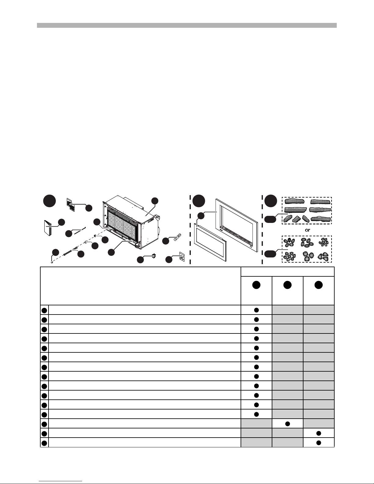
CARTON CONTENTS / ITEM CHECKLIST
The components for RHFE-952ER / RHFE-1252ER Flamefires are supplied in 3 separate cartons, the following
tables list which components are in each carton. Ensure that the components listed are present befo re proceeding
with the installation.
Component Descriptions
(Image of RHFE-952ER shown)
Carton Contents
Engine Fascia Burner
Media
RHFE-952ER / RHFE-1252ER Engine and dress guard.
Remote Control.
Fixings: Screw M4 x 20 Pan Phil Zinc (x1).
Flue Exhaust Lock (see separate Co-axial Flue Installation Manual for details).
Cable Tie 300mm.
Fascia Mounting Screws (x2 pre-installed in the engine fascia mounting brackets).
This Operation and Installation Manual.
Ceramic Granules (x2 Bags RHFE-952ER/ x3 Bags RHFE-1252ER use with Log set inst).
1/2” BSP x 5/8” UNF Flare Brass Adaptor (x1).
1/2” Flare Brass Nut (x1).
5/8” UNF Flare Brass Plug (x1).
Semi-rigid Stainless Steel gas pipe with 5/8” connections (x1).
RHFE-952ER / RHFE-1252ER - Fascia.
A. Ceramic Log Set (RHFE-952ER x8 logs, RHFE-1252ER x10 logs).
B. Ceramic Stone Set (RHFE-952ER x30 stones, RHFE-1252ER x40 stones).
A B C
1
8
6
3
4
5
7
10
11
12
13
9
14 A
or
14 B
13
2
ABC
1
2
3456789101112131414

Rinnai Australia 5 Operation & Installation Manual
INSTALLATION RECORD
INSTALLERS / GAS FITTERS DETAILS
Installer Name: ____________________________________________________________________
Company Name: ____________________________________________________________________
Company Address: ____________________________________________________________________
____________________________________________________________________
____________________________________________________________________
Company Contact Details
Telephone: ____________________________________________________________________
Mobile Phone: ____________________________________________________________________
Certificate of Compliance / Certification Number: _____________________________________________
Authorised Persons - Licence Number: _____________________________________________________
Installers Signature: ____________________________________________________________________
Installation Date: ____________________________________________________________________
APPLIANCE DETAILS
Model Number: ____________________________________________________________________
Serial Number: ____________________________________________________________________
Installation Address: ____________________________________________________________________
____________________________________________________________________
____________________________________________________________________
____________________________________________________________________
THIS APPLIANCE MUST BE INSTALLED, SERVICED AND REPAIRED ONLY BY AN AUTHORISED
PERSON.
The mesh dress guard supplied with this appliance must not be permanently re moved as it fulfils
an operational safety function. Additional dress guards including free standing types may be
used in conjunction with, but not replace, the dress guard supplied with this appliance.
WARNING
Rinnai 6 RHFE 952_1252 OIM
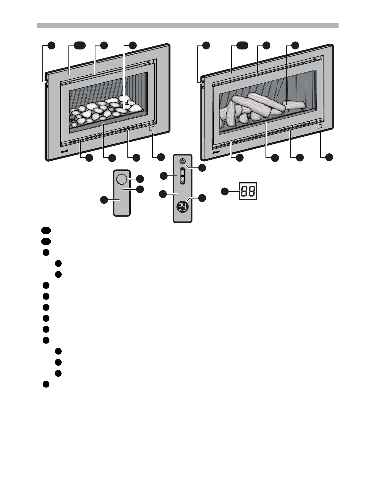
ABOUT RHFE-952ER / RHFE-1252ER SPACE HEATERS
GENERAL DESIGN LAYOUT
FEATURES
Rinnai RHFE952ER - (shown with the ceramic stone set installed)
Rinnai RHFE1252ER - (shown with the ceramic log set installed)
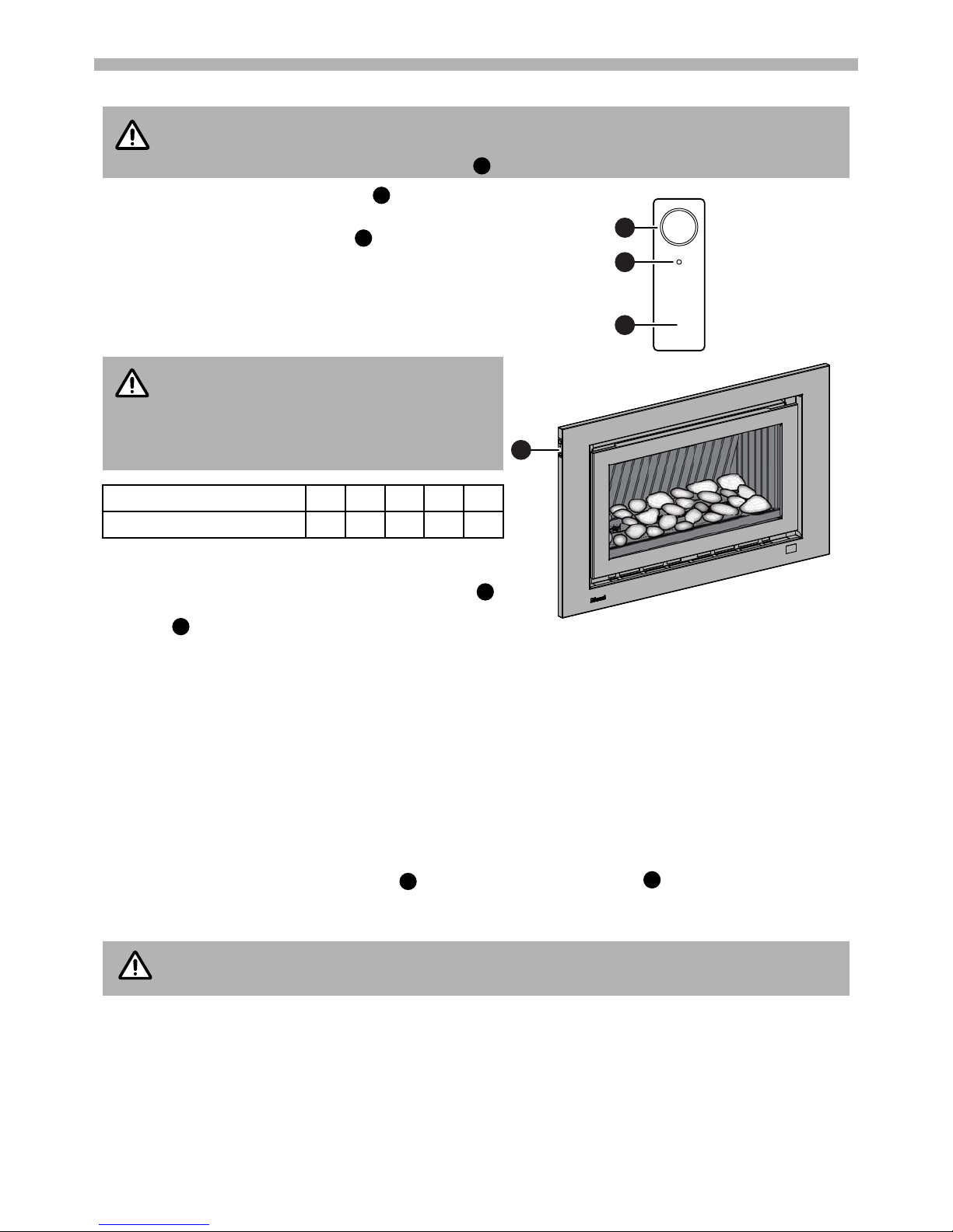
Appliance push button control panel
ON / OFF button
Standby Indicator (Red)
Room air return / Inlet filters - Dust filter meshing is fixed to the inlets of the room air return.
Glass flame window
Burner box - ceramic stone set / ceramic log set and burn media
Warm air discharge vent
Remote (IR) control receiver window
Remote (IR) control
Standby / ON button
Flame Up / Down buttons
Room temperature display (displays the current temperature of the r oom in wh ich the control is located )
Viewing window for error code display (This is located behind the fascia, see page 15 for details)
• Room Sealed: Air for combustion is taken from the outside and the flue products are exhauste d to the outside.
This means heater operation has no effect on the composition and quality of air in the room.
• Push Button Ignition: Only one touch of the STANDBY/ON switch is all that is required to operate the heater.
• Remote (IR) Control: Infra Red remote for flame height adjustment with inbuilt room temperature display.
a
b
d
e
9
2
8
9
4
3
7
9
4
3
7
2 6 5 2 61a 51b
c
1a
1b
2
a
b345678
c
d
e
9
Rinnai 7 RHFE 952_1252 OIM
SAFETY
DO NOT MODIFY THIS APPLIANCE.
Failure to comply with these instructions could result in a fire or explosion, which could cause
serious injury, death or property damage.
Improper installation, adjustments, service or maintenance can cause serious injury, death or
property damage. Such work must only be performed by an authorised person.
• The appliance must be installed in accordance with the local gas and electrical authority
regulations.
• Flue terminal must always vent directly to outdoors.
• DO NOT extend the flue vertically or horizontally in ways othe r than prescr ibed in this a ppliance
manufacturer’s installation instructions.
• For information on gas consumption, see data plate on the appliance.
• WARNING: This heater MUST NOT be used if either of the glass panels are damaged.
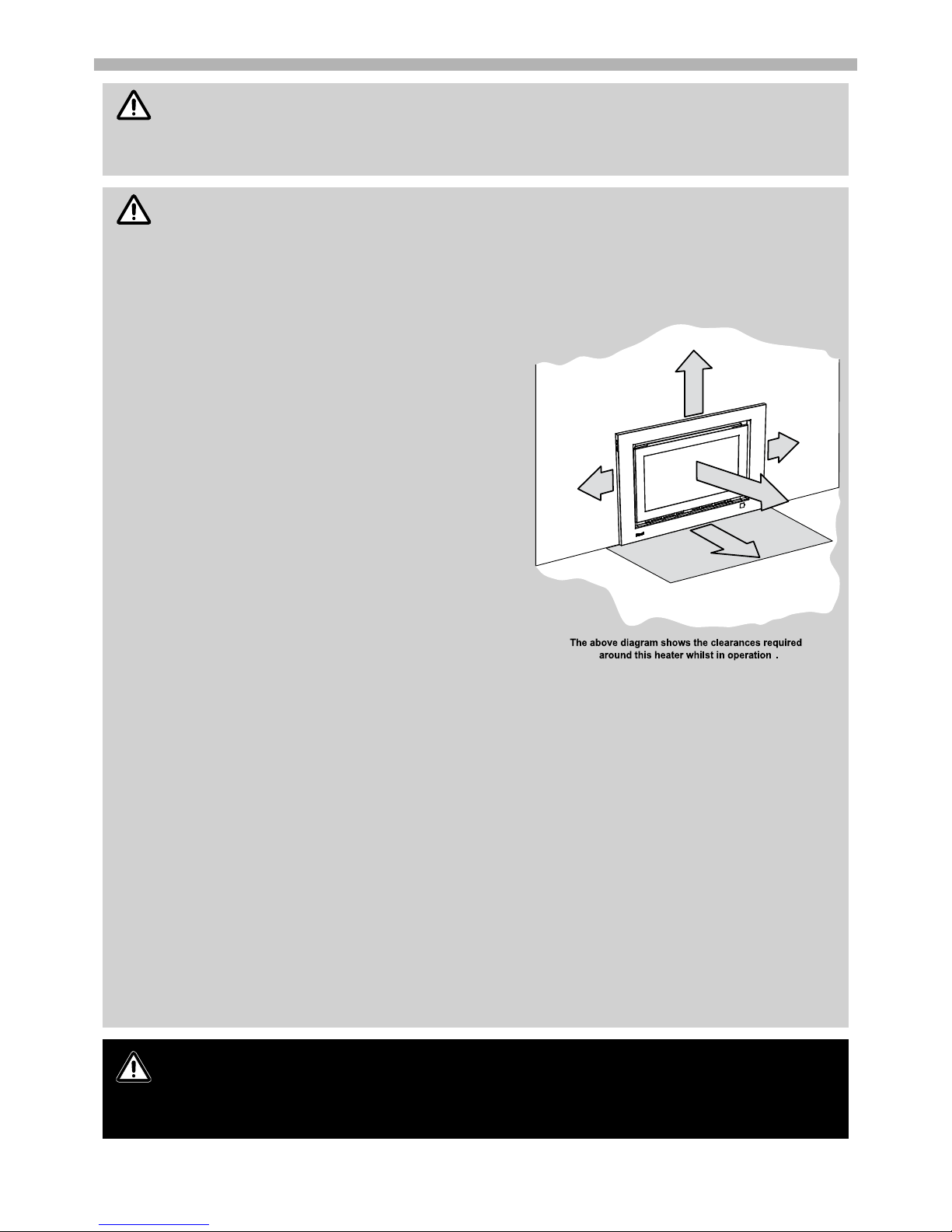
• When considering installation ensure minimum
clearances as follows are adhered to:
• Heat radiating from the front of this heater may
over time affect the appearance of some materials
used for flooring such as carpet, vinyl, cork or
timber. This effect may be amplified if the air in the
room contains cooking vapours, candle vapours
and cigarette smoke, etc. To avoid this possibility,
it is recommended that a mat or similar protective
sheet be placed in front of the appliance,
extending at least 750 mm in front of the dress
guard. Refer to page 20 for mantle clearances,
additional installation information and warnings.
• This appliance MUST NOT be installed where
curtains or other combustible materials could
come into contact with it. In some cases curtains
may need restraining.
• This appliance is NOT intended for u se by persons
(including children) with reduced physical,
sensory or mental capabilities or lack of
experience and knowledge, unless they have been
given supervision or instruction concerning use of
the appliance by a person responsible for their
safety.
• The appliance is NOT intended for use by young
children or infirm persons without supervision.
• Young Children must be supervised when in the vicinity of this heater while it is in operation.
• For protection of young children or the infirm a secondary guard is required.
• If the supply cord is damaged or requires replacing, it must be replaced by the manufacturer or
the manufacturer's agent or similarly qualified person in order to avoid a hazard.
• The heater MUST NOT be located immediately below a power socket outlet.
• A dedicated 230 V earthed 10 Amp power point must be used with this appliance.
• DO NOT modify this appliance. Modifying from original specifications may create a dangerous
situation and will void your warranty.
• Only the flue components specified by Rinnai must be used.
• Unpack the heater and check for damage. DO NOT INSTALL A DAMAGED HEAT ER. If t he hea te r
is damaged, contact your supplier for advice.
• Before installing the heater, check the label for the correct gas type (refer rating plate, inside the
appliance).
• Refer to local gas authority for confirmation of the gas type if you are in doubt.
• Suitable ONLY for indoor installation.
• DO NOT operate this appliance before leak checking hoses and gas cylinder connection.
• NOT to be connected to an LP gas cylinder located indoors.
THIS APPLIANCE MUST BE INSTALLED, SERVICED AND REPAIRED ONLY BY AN AUTHORISED
PERSON.
The mesh dress guard supplied with this appliance must not be permanently re moved as it fulfils
an operational safety function. Additional dress guards including free standing types may be
used in conjunction with, but not replace, the dress guard supplied with this appliance.
WARNING
IMPORTANT
100mm
100mm
250mm
1000mm
750mm
WARNING
Rinnai 8 RHFE 952_1252 OIM
SAFETY
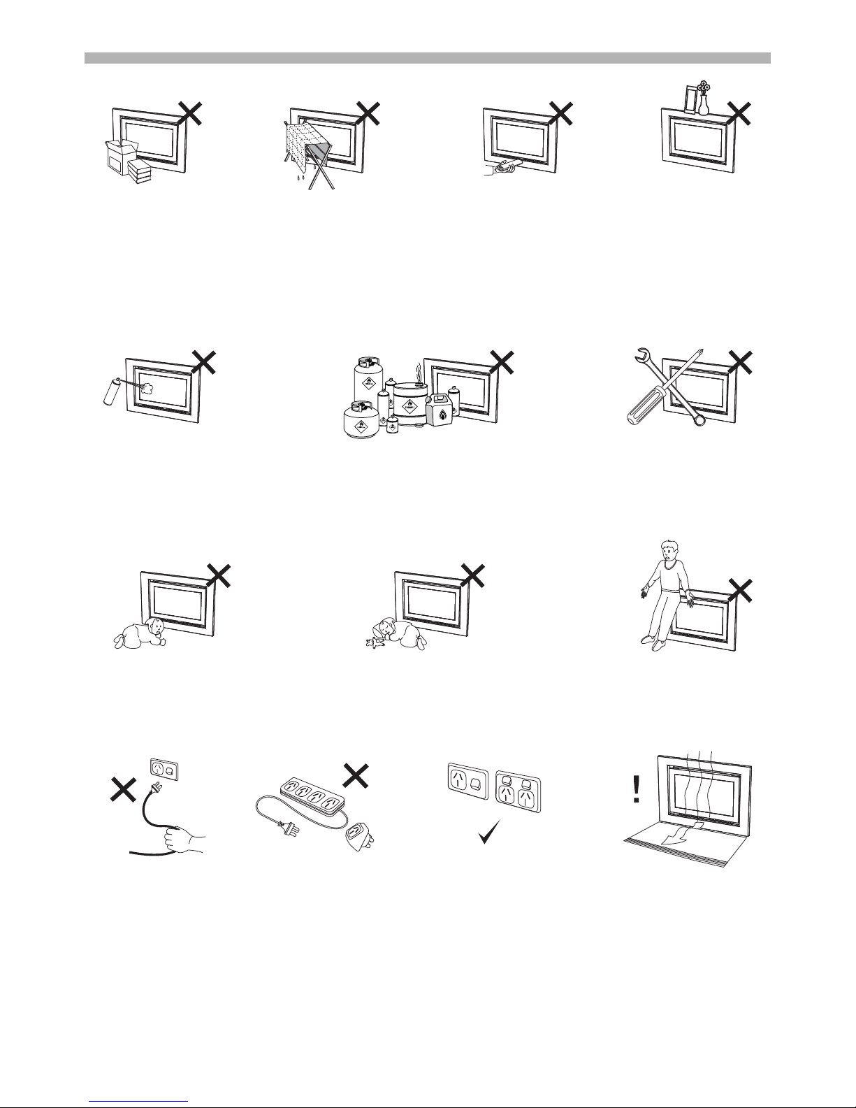
DO NOT restrict the warm air discharge by placing articles in front of the heater. This appliance must not be used
for any purpose other than heating.
DO NOT allow anyone to post articles through the louvres or let flammable and combustib le materials to come into
contact with the heater.
DO NOT place articles on or against this appliance, on the heaters top panel or obstruct the auto overheat
discharge vent.
DO NOT spray aerosols in the vicinity of this appliance whilst the heater is operating. Most aerosols contain
flammable gas, which can be a fire hazard if used near the heater when it is in use.
DO NOT store flammable materials near this appliance.
DO NOT modify this appliance.
Young children should be supervised at all times. Hand or body contact with the warm air discharge louvres and
glass must be avoided.
DO NOT allow young children or the infirm to sleep directly in front of the heater while in operation.
DO NOT allow anyone to sit on or lean against the appliance.
DO NOT unplug the heater while it is in operation or while the fans are still cycling. Unplugging the heater while in
operation may cause the over-temperature switch to activate preventing the heater from restarting.
A dedicated 230~240V 50Hz 10 Amp power point must be used with this appliance. DO NOT use power boards or
double adaptors to operate this appliance. The appliance MUST NOT BE located below a power point.
Heat emanating from the front of this appliance may over time affect the appearance of some materials used for
flooring such as carpet, vinyl, cork or timber. This effect may be amplified if the air in the room contains cooking
vapours or cigarette smoke. To avoid this possibility, it is recommended that a mat be placed in front of the
appliance, extending at least 750 mm in front of it.

Rinnai 9 RHFE 952_1252 OIM
SAFETY
SAFETY DEVICES
Initial start-up: This heater has a one-time start up cycle. Should there be a fault in the heater no more than 3
manual restarts should be attempted. If the heater still fails to operate a service call will be required. Refer to the
“CARE AND MAINTENANCE” pages; 13 through 15 for further information.
Over Heat Thermistor: Should the heater get too hot during operation, (for example when the air outlet louvres
are blocked), this device will automatically turn the gas off and allow the heater to be manually restarted, (automatic
re-start will not occur). Refer to the “CARE AND MAINTENANCE” pages; 13 through 15 for further information.
Over heat Thermal Fuse: In the unlikely event of the Over Heat Thermistor failing or some other fault occurring
the Over Heat Thermal fuse will operate completely shutting the appliance down. This device is a 'one hit' only
function, a service call will be required to reinstate operational ability to your heater. Refer to the “CARE AND
MAINTENANCE” pages; 13 through 15 for further information.
Power Failure: Refer to page 10. In the event of power failure or power disruption your heater will shut down
completely, manual restarting will be required. Refer to the “CARE AND MAINTENANCE” pages; 13 through 15
for further information.
Electric fuse: The electrical circuits are protected by a fuse. Refer to the “CARE AND MAINTENANCE” pages; 13
through 15 for further information.
Flame Failure Sensing System: These devices within the appliance automatically cut of the gas supply to the
burners in the event of a flame failure. Refer to the “CARE AND MAINTENANCE” pages; 13 through 15 for further
information.
Pressure Relief: The burner box glass panel is secured to the burner box via spring loaded pressure relief
fasteners.
Rinnai 10 RHFE 952_1252 OIM
CONTROL PANEL OPERATION
TO TURN YOUR HEATER ON
Access the 'Push Button Control Panel' . This is located
on the top left hand side of the appliance.
Step 1. Press the ON / OFF button once. You will be
able to hear the ignition sparking.
Step 2. The sparking ignition stops when the pilot flame
has been established.
The main burner then ignites off the pilot flame and
is automatically preset to Stage 5 - High Flame.
TO TURN YOUR HEATER OFF
To turn the heater ‘OFF’ press the ‘ON’/’OFF’ button
once, when the heater is in the off state the Red Power
Indicator will be extinguished.
INTERRUPTION TO ELECTRICITY OR GAS SUPPLY DURING OPERATION
Interruption to the power or gas supply will turn your heater off and a restart will be required. This is a safety feature
designed to ensure that un-attended starts do not occur after power or gas interruptions.
RESTART PROCEDURE AFTER INTERRUPTION TO ELECTRICITY SUPPLY
To restart your heater once power has been restored follow the steps for “TO TURN YOUR HEATER ON” as
above.
FULL CONTROL AND PARTIAL CONTROL
Full operation of the heater is only possible by using the remote control. In the event of a mispla ced or broken
remote control or if the batteries for the remote control are flat, this appliance may still be operated in a limited
capacity by using the power ON/OFF button of the 'Push Button Control Panel' located on the top left hand
side of the appliance.
The heater will automatically modulate between flame settings to maintain the default set temperature of 22°C.
BEFORE PROCEEDING ENSURE THE GAS AND ELECTRICITY ARE TURNED ON.
When the heater is in the OFF condition (the power supply connected and switched ON but the
heater turned OFF) the Red Power Indicator will be extinguished. This is normal.
FLAME HEIGHT AND FAN SPEED
The relationship between flame height and fan
speed is factory preset and cannot be adju st ed.
Refer to “REMOTE CONTROL OPERATION” on
the next page for Flame / Fan options.
Flame Height 12345
Fan Speed
(2 speed only) Low Low Low High High
No control of the flame or heat output is possible via the appliance ON/OFF button.
NOTE
b
b
a
2
2
2
a
NOTE
aba
2
NOTE
 Loading...