

Rinnai RHFE-950ETR, RHFE-1250ETR Operation & Installation Manual

This appliance shall be installed in accordance with:
• Manufacturer’s Installation Instructions
• Current AS/NZS 5601 AS/NZS 3000
• Local Regulations and Municipal Building Codes including local OH&S requirements
This appliance must be installed, maintained and removed by an Authorised Person.
For continued safety of this appliance it must be installed and maintained in
accordance with the manufacturers instructions.
All Rinnai gas products
are A.G.A. certified.
RHFE-950ETR
RHFE-1250ETR
OPERATION & INSTALLATION MANUAL
Power Flued Flamefire Gas Space Heaters
RHFE-950ETR & RHFE-1250ETR

Rinnai Australia 2 Operation & Installation Manual
Congratulations on the purchase of your Rinnai RHFE-950ETR or RHFE-1250ETR Flamefire.
We trust you will have many years of comfort and enjoyment from your appliance.
BEFORE PROCEEDING WITH THE OPERATION OR INSTALLATION OF YOUR NEW HEATER
PLEASE READ THIS MANUAL THOROUGHLY AND GAIN A FULL UNDERSTANDING OF THE
REQUIREMENTS, FEATURES AND OPERATION OF YOUR NEW APPLIANCE.

Rinnai 3 Operation Manual
BEFORE YOU START ................................................................................................................. 4
INSTALLATION REQUIREMENTS .................................................................................................................. 4
CERTIFICATION .............................................................................................................................................. 4
FLUE INSTALLATION MANUAL ...................................................................................................................... 4
CARTON CONTENTS / ITEM CHECKLIST ..................................................................................................... 4
ABOUT THE RHFE-950ETR / RHFE-1250ETR SPACE HEATER ............................................. 5
GENERAL DESIGN LAYOUT........................................................................................................................... 5
REMOTE CONTROL GENERAL LAYOUT ...................................................................................................... 6
REMOTE CONTROL DISPLAY ........................................................................................................................ 7
FEATURES....................................................................................................................................................... 7
UNPACKING THE APPLIANCE: ...................................................................................................................... 7
SAFETY........................................................................................................................................ 8
BASIC HEATER OPERATION .................................................................................................. 10
GENERAL NOTES ABOUT IGNITION ........................................................................................................... 10
OPERATION WITHOUT THE REMOTE CONTROL (AUTOMATIC MODE) ................................................. 10
OPERATION WITH THE REMOTE CONTROL ............................................................................................. 10
TURNING ON THE POWER .......................................................................................................................... 11
USING THE REMOTE CONTROL TO OPERATE THE HEATER ................................................................ 11
FLAME FUNCTION ........................................................................................................................................ 12
PROGRAMMED HEATER OPERATION................................................................................... 13
PROGRAMMING THE CLOCK AND TIMERS ............................................................................................... 13
USING THE TIMERS...................................................................................................................................... 13
PRE-HEAT...................................................................................................................................................... 14
USING THE OVERRIDE FUNCTION ............................................................................................................. 14
USING THE EXTRA LOW FUNCTION........................................................................................................... 14
THE LOCK FUNCTION .................................................................................................................................. 14
CARE AND MAINTENANCE ..................................................................................................... 15
CLEANING...................................................................................................................................................... 15
FILTERS ......................................................................................................................................................... 15
WARM AIR VENT ........................................................................................................................................... 15
GENERAL HEATER CHARACTERISTICS .................................................................................................... 16
SERVICE ........................................................................................................................................................ 16
TROUBLE SHOOTING CHECKLIST.............................................................................................................. 17
ERROR CODES ............................................................................................................................................. 17
INSTALLATION MANUAL......................................................................................................... 18
CONTACT INFORMATION........................................................................................................ 32
OPERATION MANUAL
Rinnai Australia 4 Operation & Installation Manual
BEFORE YOU START
INSTALLATION REQUIREMENTS
This heater must be installed by an authorised person. The installation must conform to local regulations. The
installation must also comply with the instructions supplied by Rinnai.
Service and removal must be carried out by an authorised person.
CERTIFICATION
The Rinnai RHFE-950ETR / RHFE-1250ETR has been certified by the Australian Gas Association.
The AGA Certification Number is shown on the appliance dataplate.(Located on the top right hand corner of the
right hand side panel).
No parts or functions should be modified or permanently removed from the heater.
Please keep these instructions in a safe place for future reference.
FLUE INSTALLATION MANUAL
These instructions are to be used in conjunction with the Rinnai “Power Flued Flamefire Space Heater Co-axial
Flue System Installation Manual” supplied with flue kits ASPDFK or ASPKIT03.
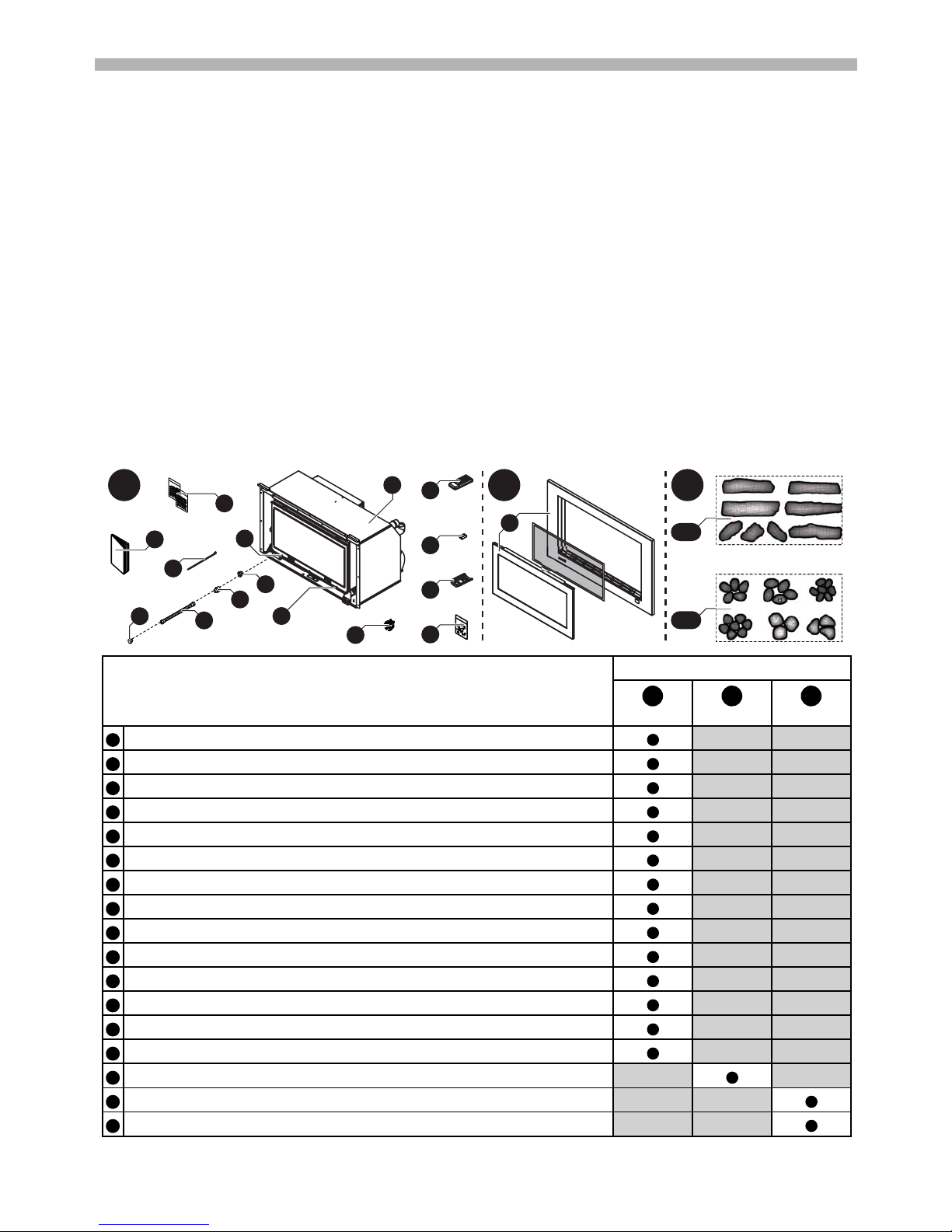
CARTON CONTENTS / ITEM CHECKLIST
The components for RHFE-950ETR / RHFE-1250ETR Flamefires are supplied in 3 separate cartons, the following
tables list which components are in each carton. Ensure that the components listed are present before proceeding
with the installation.
Component Descriptions
(Image of RHFE-950ETR shown)
Carton Contents
Engine Fascia Burn Media
RHFE-950ETR Engine only / RHFE-1250ETR Engine and dress guard.
Remote Control.
1.5V AAA Batteries (x2)
Remote Control Mounting Bracket.
Fixings: Screw 8x1 Truss PH ZP (x2), Screw M4 x 20 Pan Phil Zinc (x1).
Flue Exhaust Lock (see Co-axial Flue Installation Manual for details).
Cable Tie 300mm.
Fascia Mounting Screws (x2 pre-installed in the engine fascia mounting brackets).
This Operation and Installation Manual.
Ceramic Granules (x2 Bags RHFE-950ETR/ x3 Bags RHFE-1250ETR use with Log set inst).
1/2” BSP x 5/8” UNF Flare Brass Adaptor (x1).
1/2” Flare Brass Nut (x1).
5/8” UNF Flare Brass Plug (x1).
Semi-rigid Stainless Steel gas pipe with 5/8” connections (x1).
RHFE-950ETR - Fascia and dress guard / RHFE-1250ETR - Fascia only.
A. Ceramic Log Set (RHFE-950ETR x8 logs, RHFE-1250ETR x10 logs).
B. Ceramic Stone Set (RHFE-950ETR x30 stones, RHFE-1250ETR x40 stones).
A B C
1
8
8
2
3
4
5
6
7
9
11
12
13
14
10
16 A
or
16 B
15
A
B
C
1
2345678910111213141516
16
Rinnai Australia 5 Operation Manual
ABOUT THE RHFE-950ETR / RHFE-1250ETR SPACE HEATER
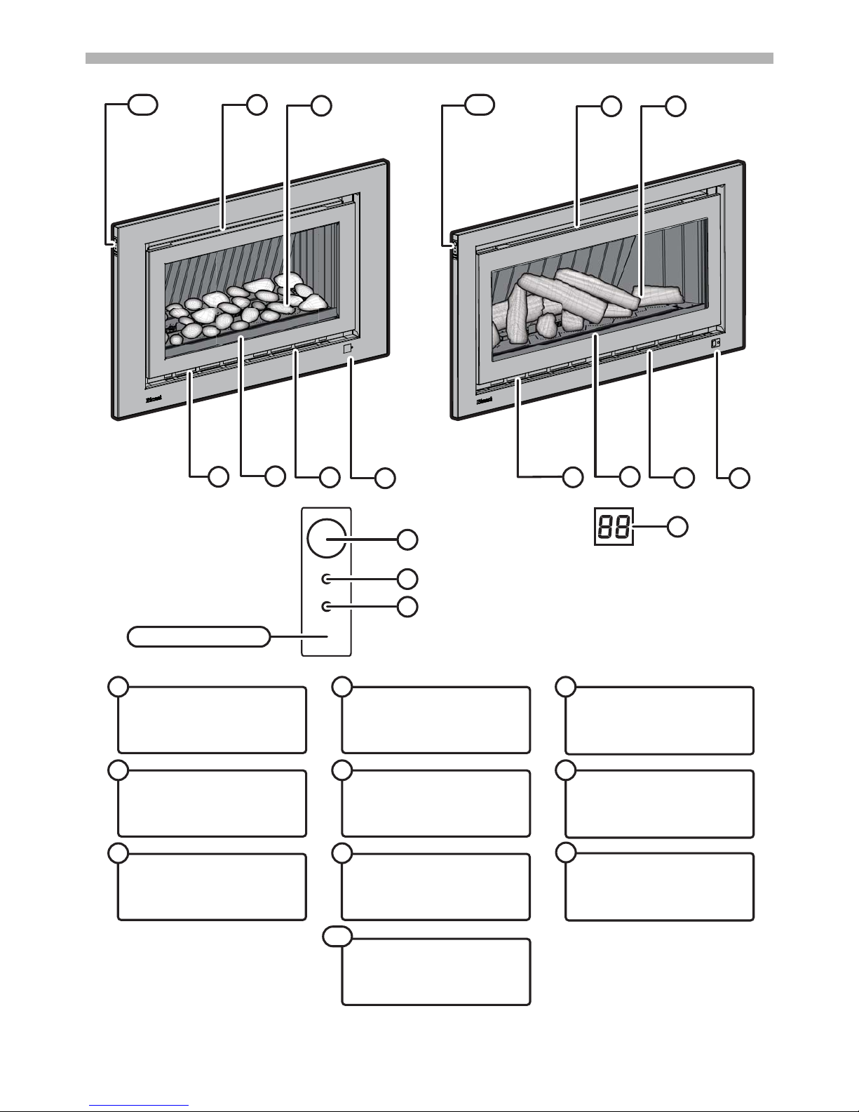
GENERAL DESIGN LAYOUT
ERROR DISPLAY
Displays error codes (located behind
fascia and viewed through grill).
1
GLASS FLAME WINDOW
2
WARM AIR DISCHARGE VENT
5
ROOM AIR RETURN /
INLET FILTERS
Dust filter meshing is fixed to the
inlets of the room air return.
3
ON / OFF BUTTON
Turns the heater On or Off.
7
RECEIVER WINDOW /
BLOCKAGE INDICATOR
Remote control receiver/
Indicator for filter/louvre blockages.
6
TIMER INDICATOR
Indicates timer program status.
9
BURNER MEDIA
Both models have the option of either
logs or stones as burner media.
4
CONTROL PANEL
10
OPERATION INDICATOR
Indicates operation status
8
6
2
4
6
2
1
1
4
3
3
5
5
10
7
1
8
CONTROL PANEL DETAIL
9
10
Rinnai Australia 6 Operation Manual
ABOUT THE RHFE-950ETR / RHFE-1250ETR SPACE HEATER
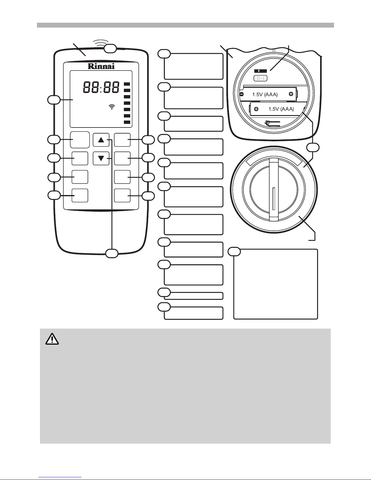
REMOTE CONTROL GENERAL LAYOUT
• Use 2 x 1.5V AAA batteries. NEVER mix old and new batteries.
• Remove batteries if the remote control is not going to be used for a long period. This will help
avoid damage from leaking batteries.
• When using “Timers” press “Override” to activate remote control functions.
• If the heater is operating in “Override” mode, using the STANDBY/ON button will cancel any
future timer operations, these will have to be reset manually.
• Some fluorescent lights may interfere with the transmission of remote control signals, in this
case changing the position from which you are operating the remote control may help.
• Avoid leaving the remote control in direct sunlight and do not place it close to the warm air
discharge louvres of the heater.
• Avoid dropping the remote control or getting it wet.
Front
Rear
STANDBY
ON
Flame
Lock
Timer 2
Timer 1
Override
Time
Set
Temperature
Lock
Clock
AM
PM
Timer 1
Set
Set ON OFF
ON OFFTimer 2 Set
Override
Extra Low
Time
Flame
20
11
21
14
15
1617
19
18
CONTROL BUTTONS
Used to select the temperature,
flame picture and adjust timers.
STANDBY / ON
BUTTON
Stops and Operates the heater
remotely.
FLAME BUTTON
Sets the flame picture.
TIME SET BUTTON
Sets clock and timers.
REMOTE DISPLAY
TIMER 1 BUTTON
Sets timer program 1.
TIMER 2 BUTTON
Sets timer program 2.
OVERRIDE BUTTON
Manually overrides
current timer operation.
LOCK BUTTON
Locks out control to
prevent tampering.
EXTRA LOW
Energy saving room temperature
control.
17
INFRA RED
EMITTER
18
20
21
19
11
12
13
14
15
16
12
13
Extra
Low
BATTERY COMPARTMENT
22
The remote control is powered by a pair of
1.5V AAA batteries. To replace batteries simply
unscrew the battery compartment cover
located on the back of the remote control
anti-clockwise, when installing new batteries
ensure that the correct polarity is observed.
The controller can display temperatures in
either Celsius or Fahrenheit, this being set
through the display switch located in the
battery compartment. To display temperatures
in Celsius (°C) set the display switch to position
`O´, to display temperatures in Fahrenheit (°F)
set the display switch to position `I´.
Display Switch (°C / °F)
Battery Compartment Cover
22
NOTE

Rinnai Australia 7 Operation Manual
ABOUT THE RHFE-950ETR / RHFE-1250ETR SPACE HEATER
REMOTE CONTROL DISPLAY
FEATURES
UNPACKING THE APPLIANCE:
Check for damage and missing parts. If the heater is damaged or missing any parts, contact your supplier for
advice. Before installing the appliance, check it is labelled for the correct gas type (see label on top rear of heater).
Refer to local gas authority for confirmation of gas type if you are in doubt.
• Room Sealed: Air for combustion is taken from the outside and the flue products are exhausted to the outside.
This means heater operation has no effect on the composition and quality of air in the room.
• Push Button Ignition: Only one touch of the STANDBY/ON switch is all that is required to operate the heater.
•Lock: When the Lock function is activated all controls other than the STANDBY/ON switch will be locked.
Deactivating the lock releases the controls. If the lock is activated when the appliance is in STANDBY, all
functions will be locked.
•Memory: The heaters micro-computer records preset temperatures, timer programming, and operational
modes. Even in the event of a power failure, the need for reprogramming is minimised.
• Dual Timer: The Dual Timer allows you to program the appliance to operate for two separate periods each
day. Once programmed the heater can then be controlled by selection of the Timer 1 and or Timer 2
functions.
The Dual Timer feature means that you can "Set and Forget" your heater. It will turn itself ON or to STANDBY
at the times you have programmed until you cancel the Timer program.
• Pre-Heat: This function automatically operates the appliance before the programmed ON time of the Timer,
in order to heat a room to the pre-set temperature by the programmed ON time.
• Remote Control: Full function cordless remote for the convenience of operating the heater from a distance.
• Extra Low Function: The Extra low function is an energy saving feature designed to control the room
temperature economically. If the room temperature continues to rise above the set temperature on thermostat
the main burner will turn down to its lowest setting. When the room temperature requires further heating the
heater will automatically re-ignite to warm the room.
MAIN DISPLAY
Displays current Clock, Timer or
Temperature status.
23
MAIN DISPLAY MODE
Indicates that controller is in Time
or Temperature display modes.
24
CLOCK SET INDICATOR
Displays when the Clock Set mode
is selected.
25
TIMER 1 INDICATOR
Displays to indicate current status
of Timer 1.
26
TIMER 2 INDICATOR
Displays to indicate current status
of Timer 2.
27
LOCK INDICATOR
Displays when the Lock mode is
activated.
28
OVERRIDE INDICATOR
Displays when Override has been
selected.
29
FLAME INDICATOR
Displays current flame picture setting
when Flame mode is activated.
31
TRANSMISSION SIGNAL
Displays when data is transmitted.
32
EXTRA LOW INDICATOR
Displays when Extra Low function
has been selected.
30
23
24
25
26
27
28
29
30
32
31
Rinnai Australia 8 Operation Manual
SAFETY
DO NOT MODIFY THIS APPLIANCE.
Failure to comply with these instructions could result in a fire or explosion, which could cause
serious injury, death or property damage.
Improper installation, adjustments, service or maintenance can cause serious injury, death or
property damage. Such work must be performed by an authorised person.
a. The appliance must be installed in accordance with the local gas and electrical authority
regulations.
b. For information on gas consumption, refer to the data plate on the appliance.
c. This appliance must not be installed where curtains or other combustible materials could
come into contact with it. In some cases curtains may need restraining.
d. Heat emanating from the front of this appliance may over time affect the appearance of
some materials used for flooring such as carpet, vinyl, cork or timber. This effect may be
amplified if the air in the room contains cooking vapours or cigarette smoke. To avoid this
possibility, it is recommended that a mat be placed in front of the appliance, extending at
least 750 mm in front of it.
e. The appliance is not intended for use by young children or infirm persons without
supervision.
f. Young children should be supervised to ensure they do not play with the appliance.
g. If the supply cord is damaged or requires replacing, it must be replaced by the
manufacturer or the manufacturer's agent or similarly qualified person in order to avoid a
hazard.
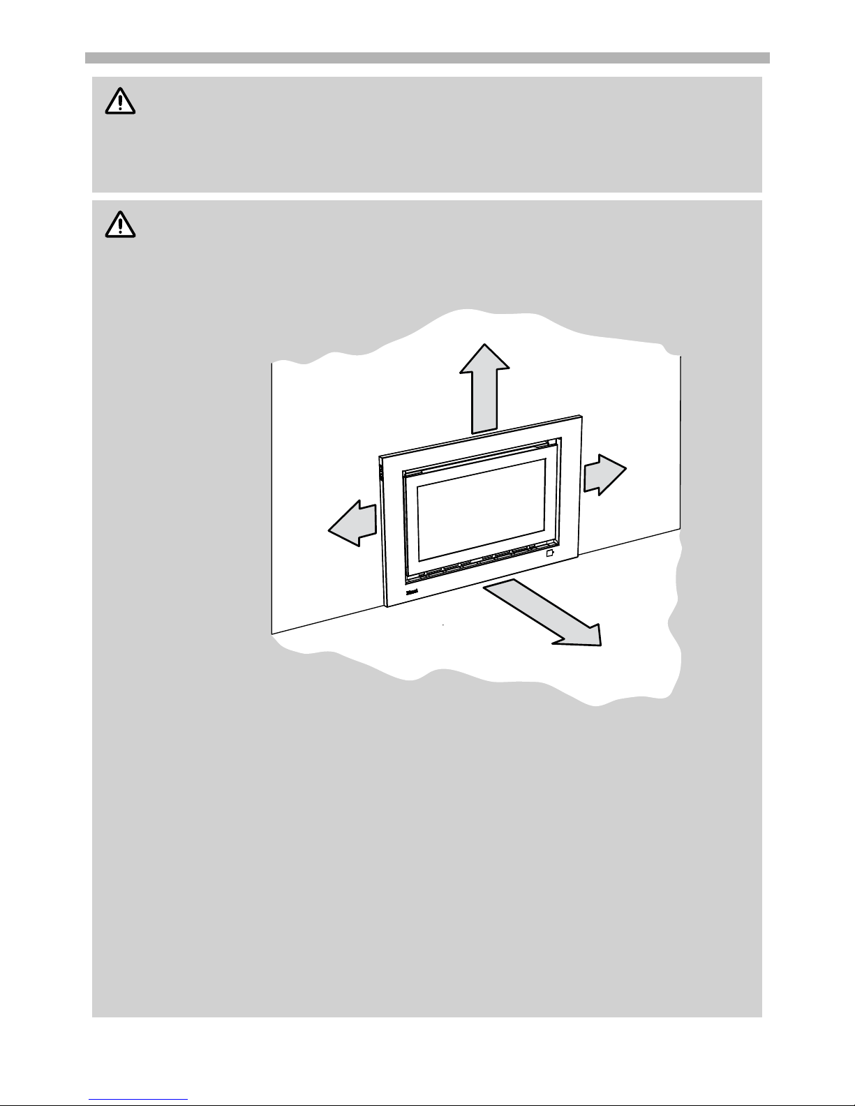
WARNING
IMPORTANT
100mm
1000mm
100mm
250mm
The above diagram shows the clearances required
around this heater whilst in operation .
Rinnai Australia 9 Operation Manual
SAFETY
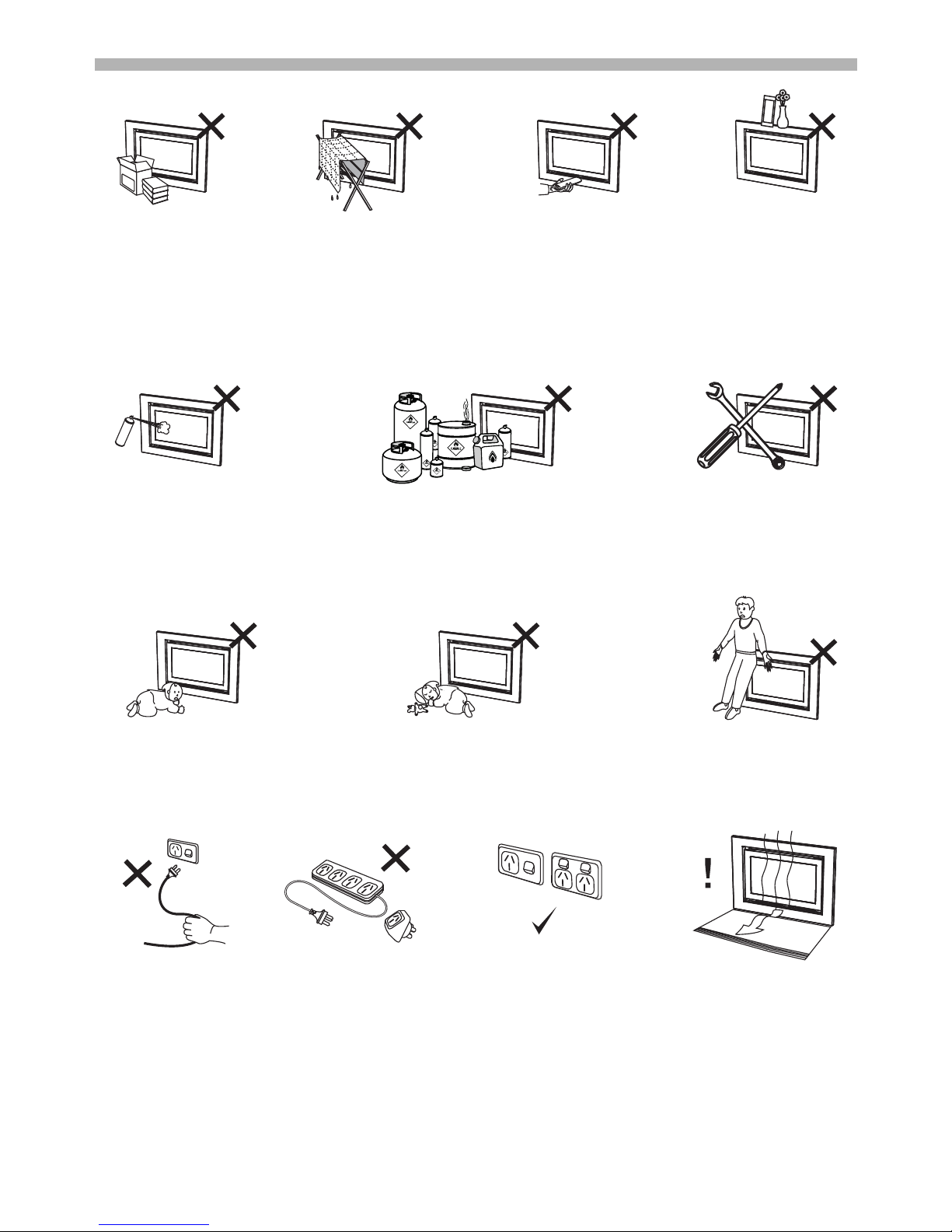
DO NOT restrict the warm air discharge by placing articles in front of the heater. This appliance must not be used
for any purpose other than heating.
DO NOT allow anyone to post articles through the louvres or let flammable and combustible materials to come into
contact with the heater.
DO NOT place articles on or against this appliance, on the heaters top panel or obstruct the auto overheat
discharge vent.
DO NOT spray aerosols in the vicinity of this appliance whilst the heater is operating. Most aerosols contain
flammable gas, which can be a fire hazard if used near the heater when it is in use.
DO NOT store flammable materials near this appliance.
DO NOT modify this appliance.
Young children should be supervised at all times. Hand or body contact with the warm air discharge louvres and
glass must be avoided.
DO NOT allow young children or the infirm to sleep directly in front of the heater while in operation.
DO NOT allow anyone to sit on or lean against the appliance.
DO NOT unplug the heater while it is in operation or while the fans are still cycling. Unplugging the heater will cause
any timer operation to stop. Timer programs are stored in the memory of the remote control.
A dedicated 230~240V 50Hz 10 Amp power point must be used with this appliance. DO NOT use power boards or
double adaptors to operate this appliance. The appliance MUST NOT BE located below a power Point.
Heat emanating from the front of this appliance may over time affect the appearance of some materials used for
flooring such as carpet, vinyl, cork or timber. This effect may be amplified if the air in the room contains cooking
vapours or cigarette smoke. To avoid this possibility, it is recommended that a mat be placed in front of the
appliance, extending at least 750 mm in front of it.
Rinnai Australia 10 Operation Manual
BASIC HEATER OPERATION
GENERAL NOTES ABOUT IGNITION
OPERATION WITHOUT THE REMOTE CONTROL (AUTOMATIC MODE)
OPERATION WITH THE REMOTE CONTROL
This appliance has a sealed combustion chamber that requires purging before gas is
allowed to flow and the ignition sequence begins. As a result the combustion fan starts
several seconds before there are any signs of ignition. The normal ignition sequence is as
follows:
1. When the On/Off button is pressed the Operation Indicator LED will glow ‘BLUE’
and Combustion fan will rotate to purge the system.
2. Ignition sparker operates.
3. As soon as a spark is sensed, gas will flow to the main burner.
4. When the main burner has established the heater will automatically modulate between
burner settings to achieve and maintain the default set temperature of 22°C.
When using the heater for the first time or after long periods of non use, ignition may not occur the
first time it is operated due to air in the gas pipes.
If ignition does not occur within approximately 60 seconds the appliance will attempt to re-light,
however if ignition continues to fail the unit will cease operation automatically. Try operating the
heater again if this occurs.
The heater may make noises after ignition or extinction. This is due to expansion and contraction
of the internal components and is normal page 16 for details.
The heater will not ignite if the ON/OFF button is pressed straight after extinction. After
approximately 20 seconds “purge period” has passed the unit will automatically go into ignition
mode.
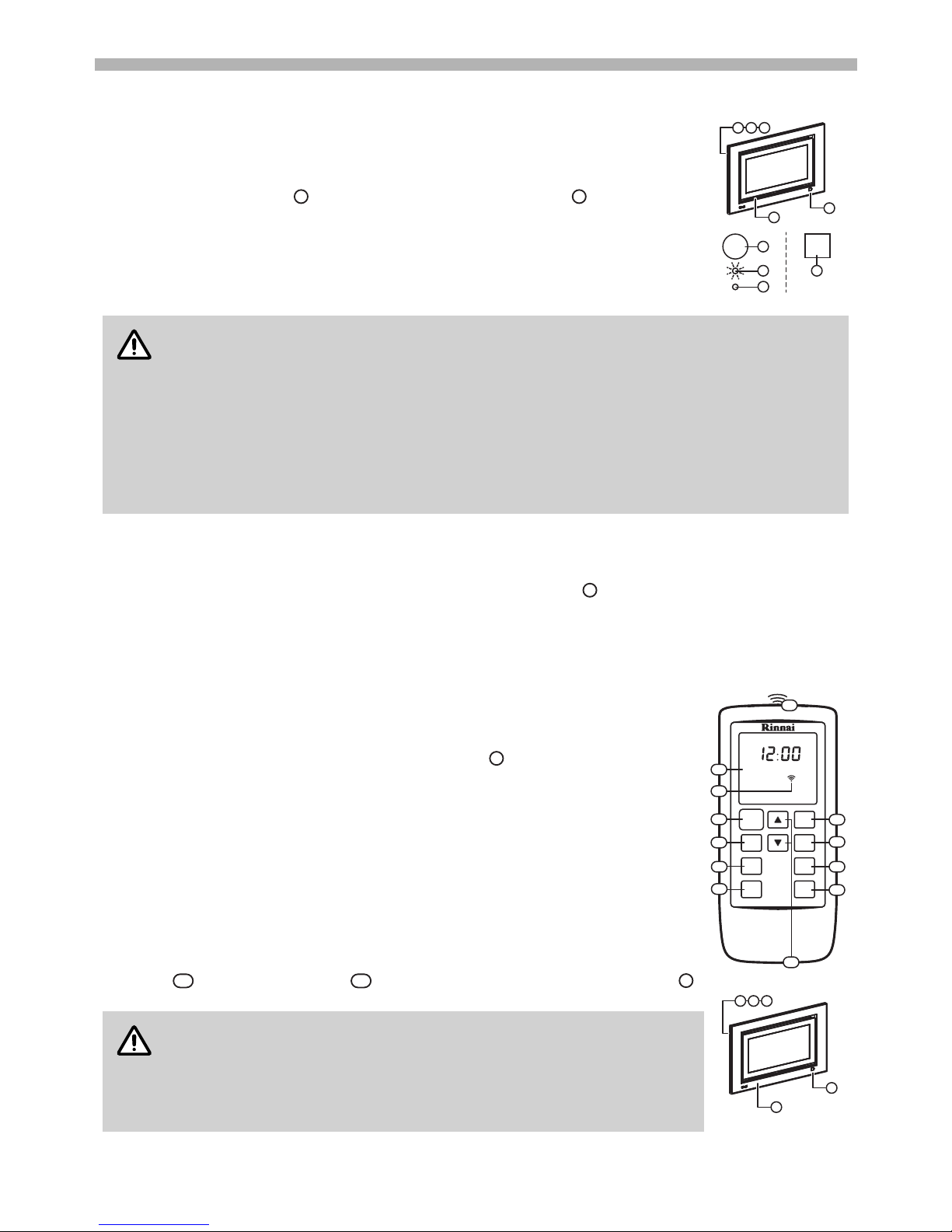
The remote control stores the clock, timer and temperature settings for the heater. The heater can be operated and
stopped without the remote control by simply using the On/Off button on the left hand side of the heater.
Operation in this manner is known as automatic mode. In automatic mode the default set temperature is 22°C. For
operation in other modes the remote control must be used.
For the remote control functions to be available, the heater must be switched between
standby and off using the remote control.
The remote control emits an Infra Red (IR) signal and must be aimed at the receiver unit
located on the bottom right hand corner of the front panel . The normal operating range
is approximately 5 metres, up to an angle of approximately 40 degrees to the horizontal. This
range may vary depending on the position of the installation and the strength of the remote
controller batteries. The remote control transmits information to the heater whenever a
button is pressed except as follows:
1. When the remote control display is de-activated and any button is pressed to restore
the display
2. When the lock function is activated
When the timers are being set, timer information is transmitted only when the ‘Time Set’
button is pressed.
Signal transmissions are confirmed by a brief illumination of the Transmission Signal
Indicator on the Remote Display and at the heater the Remote Control Indicator
will flash and a beep will sound to confirm that the settings have been received.
When the remote control is not used for a period of approximately 5 seconds
the display will then default to stand-by mode, displaying only the time.
To re-activate the remote control press any button on the keypad. This
returns the display to the previous mode. No information is transmitted from
the controller to the heater when re-activating the display.
7
8
7
8
9
1
6
1
987
NOTE
7
6
32
20
6
STANDBY
ON
Flame
Extra
Low
Lock
Timer 2
Timer 1
Override
Time
Set
Temperature
Lock
Clock
AM
PM
Timer 1
Set
Set ON OFF
ON OFFTimer 2 Set
OverrideAuto O
Time
Flame
20
32
21
14
15
1617
19
18
11
13
12
6
1
987
NOTE
 Loading...