

Rinnai RHFE-557FTR, RHFE-309FT, RHFE-556FTR, RHFE-556FDT, RHFE-559FT Installation Manual
...
To Suit Models:
RHFE-308FTR
RHFE-309FT
RHFE-556FTR
RHFE-556FDT
RHFE-557FTR
RHFE-559FT
RHFE-1004FTR
RHFE-1004FDT
Energysaver Space Heater
Co-Axial Flue System
Installation Manual
These components shall be installed in accordance with:
• Manufacturer’s Installation Instructions
• Current AS/NZS 3000, AS/NZS 3500 & AS 5601
• Local Regulations and Municipal Building Codes
THESE COMPONENTS MUST BE INSTALLED, SERVICED AND REMOVED BY AN AUTHORISED PERSON!
ONLY THE FLUE SYSTEM COMPONENTS SPECIFIED IN THIS MANUAL MUST BE USED. COMPONENTS
NOT SPECIFIED IN THIS MANUAL, WHETHER MANUFACTURED BY RINNAI OR OTHERWISE, ARE NOT
COMPATIBLE AND “MUST NOT” BE USED!

The Rinnai Energysaver® Co-Axial flue is certified as part of the
Rinnai Energysaver space heaters that have the designation ‘RHFE’ in
the model number .
Only an authorised person must install, service and remove the
Rinnai Energysaver® space heater & flue system.
Only the flue system components described in this manual must be
used.
Components that are not described in this manual, whether
manufactured by Rinnai or otherwise, are not compatible and must
not be used. Rinnai appliance warranty conditions may be voided if
non Rinnai flue components are fitted.
Rinnai New Zealand Ltd. i ES Flue Installation Manual
CONVENTIONS USED IN THIS MANUAL . . . . . . . . . . . . . . . . . . . . . . . . . . . . . . . . . . . . . . . . . . . . . . . . . . . . . . . . 1
REGULATIONS, CLEARANCES & GENERAL INFORMATION . . . . . . . . . . . . . . . . . . . . . . . . . . . . . . . . . . . . . . . 2
FLUE TRANSITION CONNECTIONS . . . . . . . . . . . . . . . . . . . . . . . . . . . . . . . . . . . . . . . . . . . . . . . . . . . . . . . . . . . . . . . . . . . .3
LOCATION. . . . . . . . . . . . . . . . . . . . . . . . . . . . . . . . . . . . . . . . . . . . . . . . . . . . . . . . . . . . . . . . . . . . . . . . . . . . . . . . . . . . . . . . .3
LUBRICATING INNER PIPE COMPONENTS. . . . . . . . . . . . . . . . . . . . . . . . . . . . . . . . . . . . . . . . . . . . . . . . . . . . . . . . . . . . . .3
INSTALLATION CONFIGURATIONS. . . . . . . . . . . . . . . . . . . . . . . . . . . . . . . . . . . . . . . . . . . . . . . . . . . . . . . . . . . . 4
WALL PENETRATIONS . . . . . . . . . . . . . . . . . . . . . . . . . . . . . . . . . . . . . . . . . . . . . . . . . . . . . . . . . . . . . . . . . . . . . . 6
FLUE KIT COMPONENTS . . . . . . . . . . . . . . . . . . . . . . . . . . . . . . . . . . . . . . . . . . . . . . . . . . . . . . . . . . . . . . . . . . . . 8
FLUE COMPONENT ASSEMBLY . . . . . . . . . . . . . . . . . . . . . . . . . . . . . . . . . . . . . . . . . . . . . . . . . . . . . . . . . . . . . . 9
CREATING A “DIRECT” FLUE INSTALLATION . . . . . . . . . . . . . . . . . . . . . . . . . . . . . . . . . . . . . . . . . . . . . . . . . . . . . . . . . . .9
CREATING A “DIRECT EXTENDED” FLUE INSTALLATION. . . . . . . . . . . . . . . . . . . . . . . . . . . . . . . . . . . . . . . . . . . . . . . .10
CREATING AN “EXTERNAL WALL” FLUE INSTALLATION . . . . . . . . . . . . . . . . . . . . . . . . . . . . . . . . . . . . . . . . . . . . . . . .11
CREATING A “SIDEWAYS” FLUE INSTALLATION . . . . . . . . . . . . . . . . . . . . . . . . . . . . . . . . . . . . . . . . . . . . . . . . . . . . . . .13
CREATING AN “UNDER FLOOR” FLUE INSTALLATION . . . . . . . . . . . . . . . . . . . . . . . . . . . . . . . . . . . . . . . . . . . . . . . . . .15
CUTTING ~ ESDFK
, ESPIPE900 & ESROOFCOWL . . . . . . . . . . . . . . . . . . . . . . . . . . . . . . . . . . . . . . . . . . . . . . . . . . . . . . .17
COMPONENT ASSEMBLY & CONNECTION ~ ESPIPE900 . . . . . . . . . . . . . . . . . . . . . . . . . . . . . . . . . . . . . . . . . . . . . . . . .17
ASSEMBLING WALL TERMINAL ~ ESDFK & ESPIPE900. . . . . . . . . . . . . . . . . . . . . . . . . . . . . . . . . . . . . . . . . . . . . . . . . .18
ASSEMBLING AN ON-WALL TERMINAL ~ ESWTERM, ESBEND & ESPIPE900. . . . . . . . . . . . . . . . . . . . . . . . . . . . . . . .18
COMPONENT ASSEMBLY & CONNECTION ~ ESBEND . . . . . . . . . . . . . . . . . . . . . . . . . . . . . . . . . . . . . . . . . . . . . . . . . . .19
COMPONENT ASSEMBLY & CONNECTION ~ ESCONDK. . . . . . . . . . . . . . . . . . . . . . . . . . . . . . . . . . . . . . . . . . . . . . . . . .19
COMPONENT ASSEMBLY & CONNECTION ~ ESROOFCOWL . . . . . . . . . . . . . . . . . . . . . . . . . . . . . . . . . . . . . . . . . . . . .19
CREATING AN “IN-WALL” FLUE INSTALLATION ~ ESFKIT03 . . . . . . . . . . . . . . . . . . . . . . . . . . . . . . . . . . . . . . . . . . . . .20
CONNECTING HEATER EXHAUST & AIR SUPPLY. . . . . . . . . . . . . . . . . . . . . . . . . . . . . . . . . . . . . . . . . . . . . . . 23
CONNECTING HEATER EXHAUST . . . . . . . . . . . . . . . . . . . . . . . . . . . . . . . . . . . . . . . . . . . . . . . . . . . . . . . . . . . . . . . . . . . .23
CONNECTING COMBUSTION AIR HOSE . . . . . . . . . . . . . . . . . . . . . . . . . . . . . . . . . . . . . . . . . . . . . . . . . . . . . . . . . . . . . . .24
CONTACT INFORMATION . . . . . . . . . . . . . . . . . . . . . . . . . . . . . . . . . . . . . . . . . . . . . . . . . . . . . . . . . . . . . . . . . . 26
TABLE OF CONTENTS
Rinnai New Zealand Ltd. 1 ES Flue Installation Manual
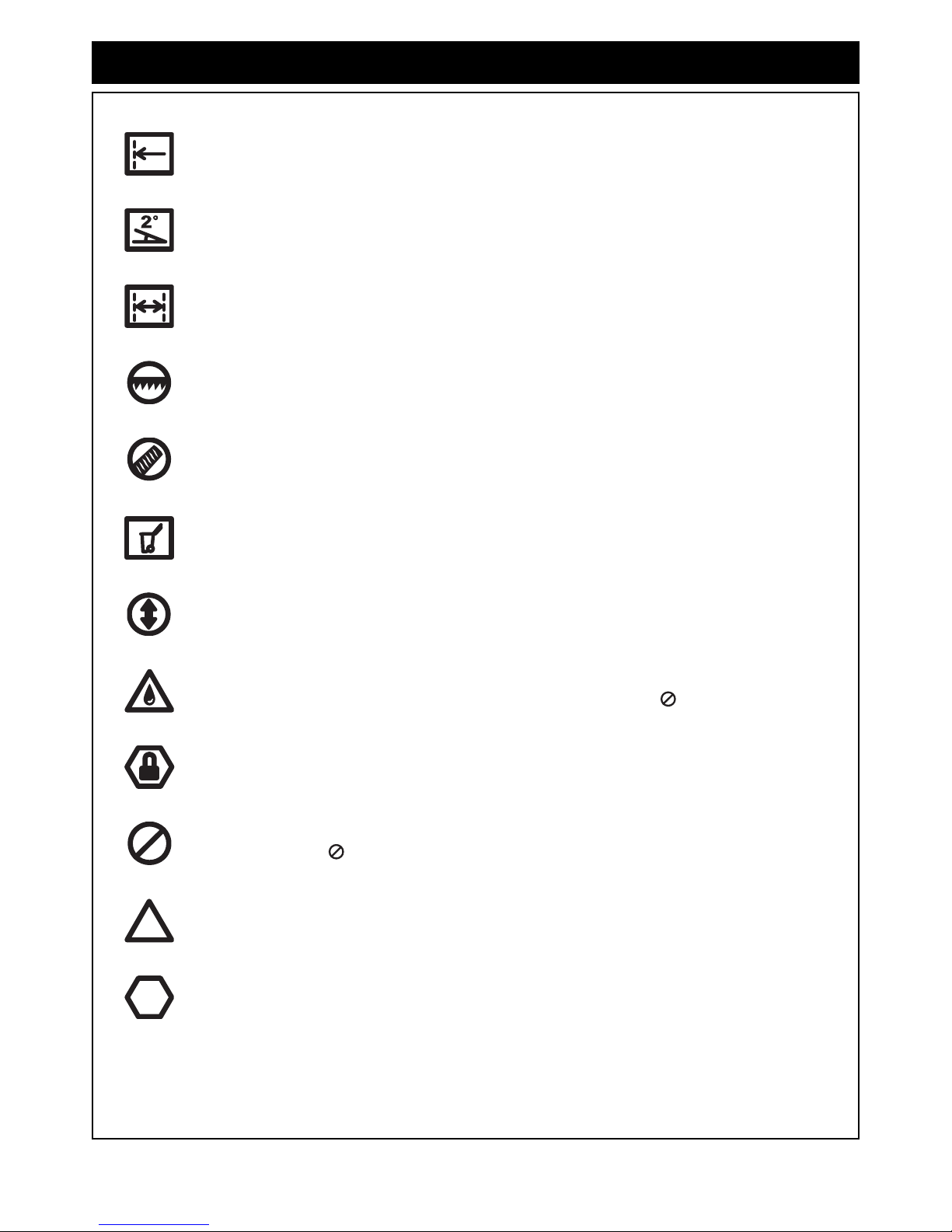
CONVENTIONS USED IN THIS MANUAL
The following symbols are used to highlight sp ecic requirements during installation steps.
The heater and the flue system shall be installed in accordance with the following:
CLEARANCES
Where required clearances will be provided and must be observed.
FALL
Ensure that the specified 2° fall is maintained to either the terminal or condensate trap.
MEASURE
Required measurements will be provided and MUST BE observed for correct installation.
CUT
Cut as required to the specified measurements.
FINISH
Ensure that burrs and swarf are removed from all cut ends.
DISCARD
Denotes items that are not required for the specific installation.
OBSERVE CORRECT ORIENTATION
Where specified ensure that components are installed with the correct vertical or horizontal
orientation.
LUBRICATE
Use the supplied container of silicon grease to lubricate components. DO NOT use other
lubricants as these may damage the flue components.
SECURE
Where specified secure components with either install
er provided or component supplied fixings.
DO NOT
Failure to observe DO NOT instructions will void the warranty of an appliance and may cause
injury or death.
NOTE / IMPORTANT
Important notes or general hints and guides provided to ease the installation.
CAUTION
Caution notes and or warnings that MUST BE observed for safe and correct installations.
!
!
Rinnai New Zealand Ltd. 2 ES Flue Installation Manual
REGULATIONS, CLEARANCES & GENERAL INFORMATION
• The requirements of the current version of AS 5601 (Gas Installations)
Note that AS 5601-2004 is referred to in this instruction and was current at the time of printing, but may have
since been superseded. It is the Installer’s responsibility to ensure that requirements of the current version of
AS 5601 are met.
• Manufacturers installation instructions.
Before commencing an installation, read the installation sections of the ‘Customer and Installation Manual’
supplied with the heater.
• Local & Municipal building codes.
• Any other relevant Statutory Regulation.
• Rinnai Energysaver space heater when co rrectly installed with Rin nai a pproved flue components are roomsealed appliances and no internal ventilation is required.
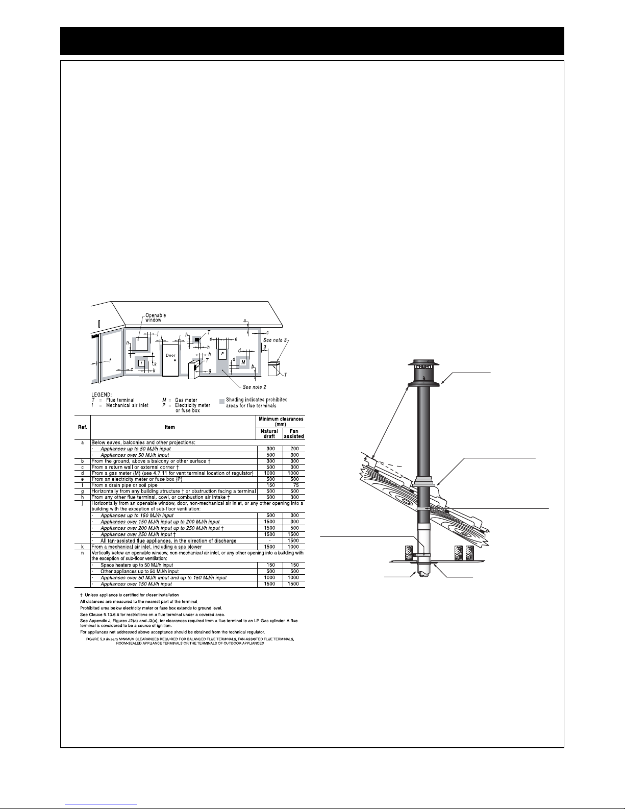
• Rinnai Energysaver space heater is fan-assisted. Therefore the fan assisted flue clearance dimensions from
AS 5601 extract shown on this page must be used.
• The o uter pla stic se ction o f the Co-Axial flue complies with temperature ha zard requirements an d ca n be
installed with zero clearance to combustible material.
• Vertical clearances when using a roof terminal (ESROOFCOWL) are shown in Fig.1.
If in doubt contact Rinnai.
Horizontal Clearances (Extract AS 5601-2004 5.13.6.5 Fig. 5.3)
Vertical Clearances Fig.1
Minimum Clearance 500 mm
ESROOFCOWL
Decktite or lead collar flashing
ESPLATE
ESPIPE900
Flue pipe clip supplied with ESPIPE900
Flue pipe clip supplied with ESROOFCOWL
Rinnai New Zealand Ltd. 3 ESFlue Installation Manual
REGULATIONS, CLEARANCES & GENERAL INFORMATION
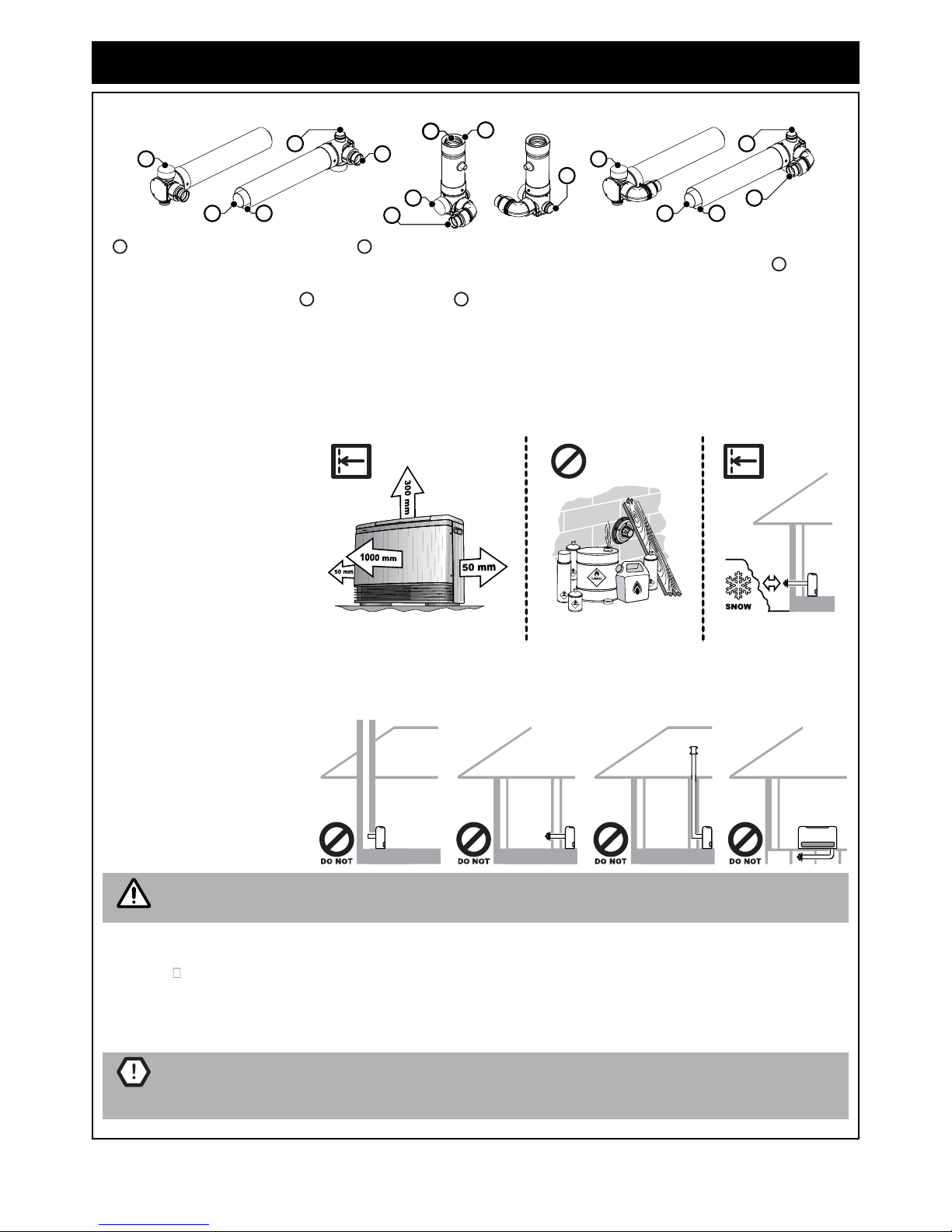
FLUE TRANSITION CONNECTIONS
Flue exhaust connection to heater. Combustion air inlet connection to heater (Right hand ~ Small connection
for models 308, 309, 556, 557, 559 heaters. Left hand ~ Large connection for model 1004 heaters). Rubber
combustion air inlet cap (when fitted) is designed to fit both the large and small combustion air inlet and MUST
cover the air inlet not in use. Combustion air inlet. Exhaust outlet.
LOCATION
LUBRICATING INNER PIPE COMPONENTS
The inner
ue pipe joints are sealed with an “O” ringseal.
To help ensure a good seal and to ease assembly, a small tub of silicone grease is provided with the Direct Flue
Kit (ESDFK) and the In-Wall Transition Kit (ESKIT03). Use this silicone grease tolubricatethe “O” ring on the inner
pipes prior to assembly.
This appliance is NOT suitable for inbuilt installations.
This appliance MUST NOT be installed where curtains or other combustible materials could come into contact with
it. In some cases curtains may need restraining.
Heat emanating from the front
of this appliance may over time
affect t
he appearance of some
materials used for flooring such
as carpet, vinyl, cork or timber.
This effect may be amplified if
the air in the room contains
cooking vapours or cigarette
smoke. To avoid this possibility
it is recommended that a mat be
placed in front of the appliance,
extending at least 750 mm in
front of it.
The flue terminal MUST BE positioned away from flammable materials.
In areas subject to heavy snowfall, keep snow clear of flue terminal at all times.
• DO NOT flue into natural
draught flues or fireplaces.
• DO NOT flue into other
rooms, roof spaces or into
under floor spaces.
• DO NOT install the heater
an unusually dust
y area.
For other important information regarding the location of the heater refer to the instructions
supplied with the appliance.
Use ONLY the supplied silicone based “O Ring” seal lubricant.
DO NOT use petroleum based lubricants such as petroleum jelly. Petroleum jelly or similar
petroleum based lubricants will cause deterioration of the ‘O’ ring seals.
2
1
3
1
3
5
4
3
1
4
2
5
2
5
4
1 2
3
4 5
DO NOT
IMPORTANT
CAUTION
Rinnai New Zealand Ltd. 4 ES Flue Installation Manual
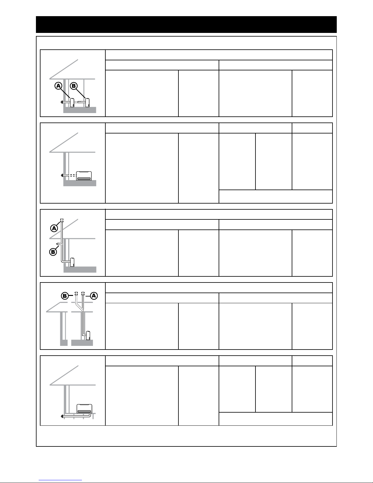
INSTALLATION CONFIGURATIONS
The following configurations are currently available. For alternative configurations contact Rinnai.
DIRECT/EXTENDED Components
Option A (Direct) Option B (Direct Extended)
Direct Flue Kit ESDFK Direct Flue Kit
Co-Ax Pipe 900mm (Optional) #
ESDFK
ESPIPE900
SIDEWAYS Components Back Cover Kit Depth
Direct Flue Kit
Co-Ax Pipe 900mm #
Back Cover Kit
ESDFK
ESPIPE900
(refer page 8 for Kit
contents)
308
309
556
557
559
1004
ESBSKA
ESBSKE
ESBSKB
ESBSKC
ESBSKF
ESBSKD
200 mm
205 mm
200 mm
200 mm
205 mm
200 mm
A Back Cover Kit is required when the flue system is installed
in a sideways configuration.
EXTERNAL WALL Components
Option A (Vertical Termination) Option B (On Wall Termination)
Direct Flue Kit
Co-Ax Pipe 900mm #
Bend (2 x 45º)
Condensate Trap
Roof Cowl
ESDFK
ESPIPE900
ESBEND
ESCONDK
ESROOFCOWL
Direct Flue Kit
Co-Ax Pipe 900mm #
Bend (45º) x2
Condensate Trap
Wall Terminal Kit
ESDFK
ESPIPE900
ESBEND
ESCONDK
ESWTERM
IN-WALL Components
Option A (Direct) Option B (Offset)
Vertical Adaptor Kit §
Co-Ax Pipe 900mm #
Roof Cowl
ESKIT03
ESPIPE900
ESROOFCOWL
Vertical Adaptor Kit §
Co-Ax Pipe 900mm #
Bend (45º) x2
Roof Cowl
ESKIT03
ESPIPE900
ESBEND
ESROOFCOWL
UNDER FLOOR Components Back Cover Kit Depth
Direct Flue Kit
Co-Ax Pipe 900mm #
Bend (2 x 45º)
Wall Terminal Kit
Back Cover Kit
ESDFK
ESPIPE900
ESBEND
ESWTERM
(refer page 8 for Kit
contents)
308
309
556
557
559
1004
ESBSKA
ESBSKE
ESBSKB
ESBSKC
ESBSKF
ESBSKD
200 mm
205 mm
200 mm
200 mm
205 mm
200 mm
A Back Cover Kit is required when the flue system is installed
in a under floor configuration.
# Order lengths as required § Includes Condensate Trap (ESCONDK)
Rinnai New Zealand Ltd. 5 ES Flue Installation Manual
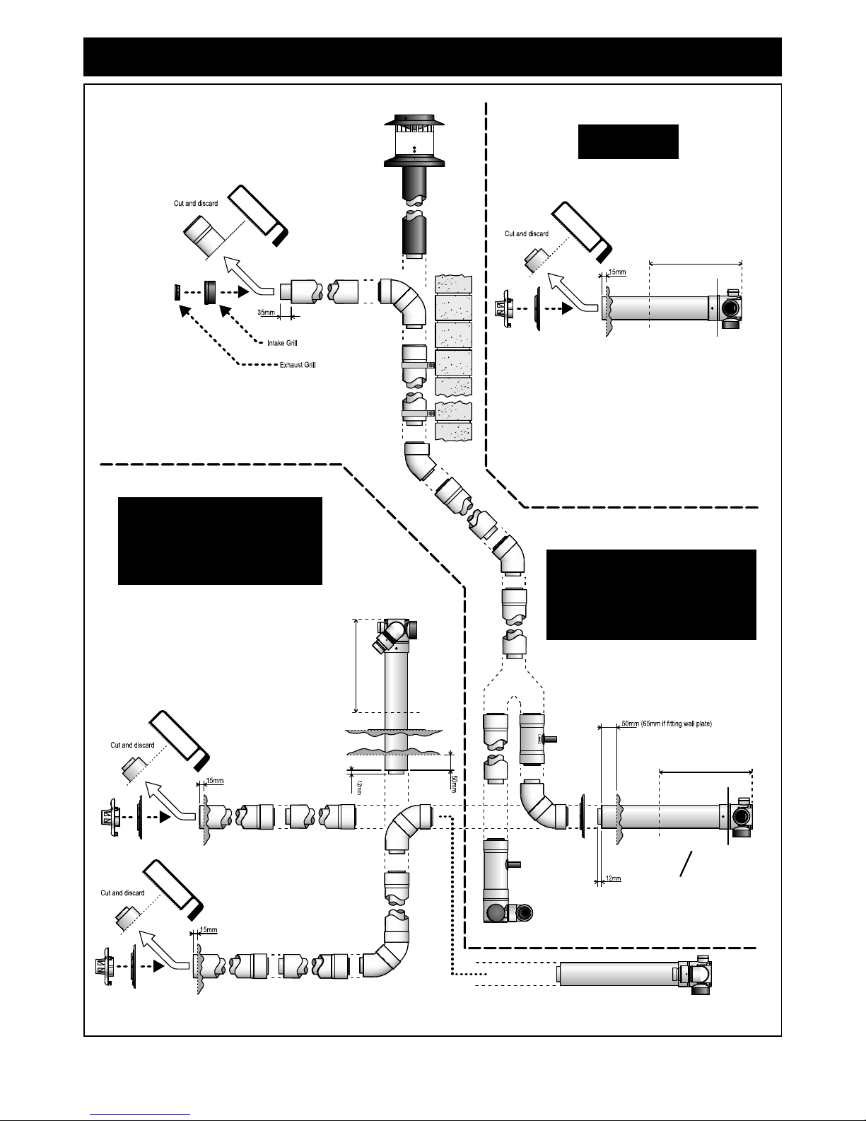
INSTALLATION CONFIGURATIONS
When cutting the flue transition
for joining to other components
the minimum total length is not
to be less than 300mm!
When cutting the flue transition
for joining to other components
the minimum total lengthis not
to be less than 300mm!
• DIRECT EXTENDED
• EXTERNAL WALL
• IN-WALL
• DIRECT EXTENDED
• UNDER FLOOR
•SIDEWAYS
SIDEWAYS
IN-WALL
EXTERNAL
WALL
DIRECT
EXTENDED
UNDER FLOOR
When cutting the flue transition
for joining to other components
the minimum total length is not
to be less than 300mm!
DIRECT
•DIRECT
Rinnai New Zealand Ltd. 6 ES Flue Installation Manual
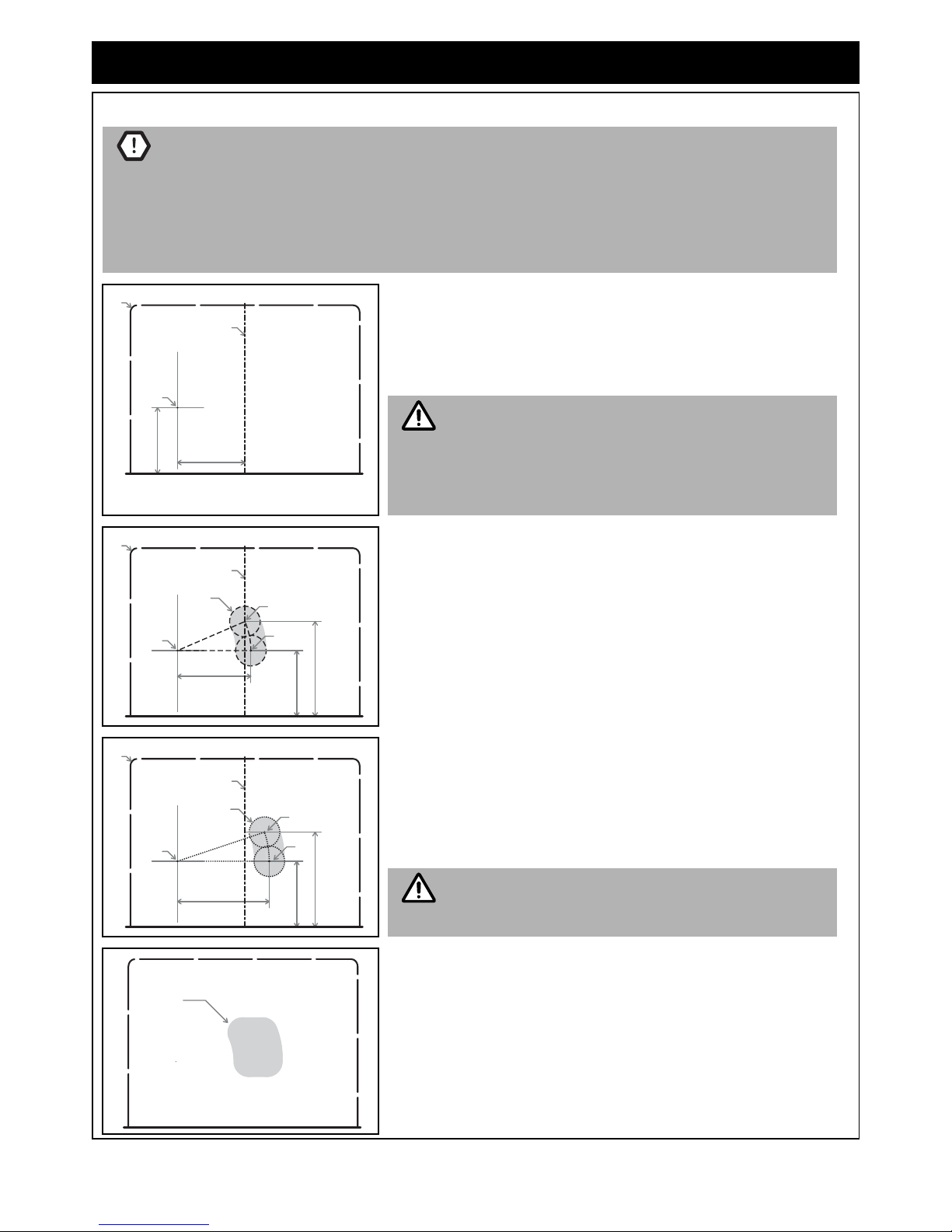
WALL PENETRATIONS
It is critical that any wall penetrations are located correctly.
Ensure there are no wall studs, noggins, wiring or other obstruction within the wall cavity where
the flue is proposed to penetrate.
Ensure the location of the flue terminal can comply with the requirements of AS 5601. Figure 5.3
from AS 5601-2004 and additional information is shown on page 2.
Especially relevant is the requirement to have a minimum of 300mm clearance between the flue
terminal a nd t he finish ed ground lev el. It is not pe rmissible to excavate a ho le t o ob tain the
required 300mm clearance, unless there is sufficient drainage provision.
1. Select the desired location i for the Energysaver Heater.
2. Find th e v ertical ce ntre lin e of the a ppliance ii an d mar k th is
location on the wall.
3. Using Measurements A & B from Table 1, mark off the arc centre
iii on the wall.
The arc centre iii corresponds to the pivot point centre
of the telescopic flue elbow on the heater.
The RHFE-308 and RHFE-309 have a fixed length nontelescopic flue elbo w. Hen ce ac curate marking of th e
penetration a rc a nd a ssociated a rea are th erefore
especially critical.
4. From the arc axis iii use the measurements C, D & E from Table
1. to draw an arc on the wall.
The lowe r end poin t of th e ar c iv will be the lower limit of the
minimum horizontal and vertical centre of penetration G.
The upper end point of the arc v will the be the upper limit of the
minimum horizontal and vertical centre of penetration G.
5. From the arc axis iii use the measurements F, D & E from Table
1. to draw an arc on the wall.
The lowe r end poin t of th e ar c vi will be the lower limit of the
maximum horizontal and vertical centre of penetration G.
The upper end point of the arc vii will be the upper limit of the
maximum horizontal and vertical centre of penetration G.
Due to the fixed length non-telescopic flue elbow of the
RHFE-308 and RHFE-309 model heaters measurements
C & F are the same for these model only.
6. The penetration may be mad e anywhere within the confines of
the shaded minimum and maximum areas viii defined by the two
arcs.
CAUTION
B
A
iii
i
ii
IMPORTANT
G
D
E
C
iii
iv
v
i
ii
D
E
F
iii
vi
vii
G
i
ii
IMPORTANT
viii
Rinnai New Zealand Ltd. 7 ES Flue Installation Manual
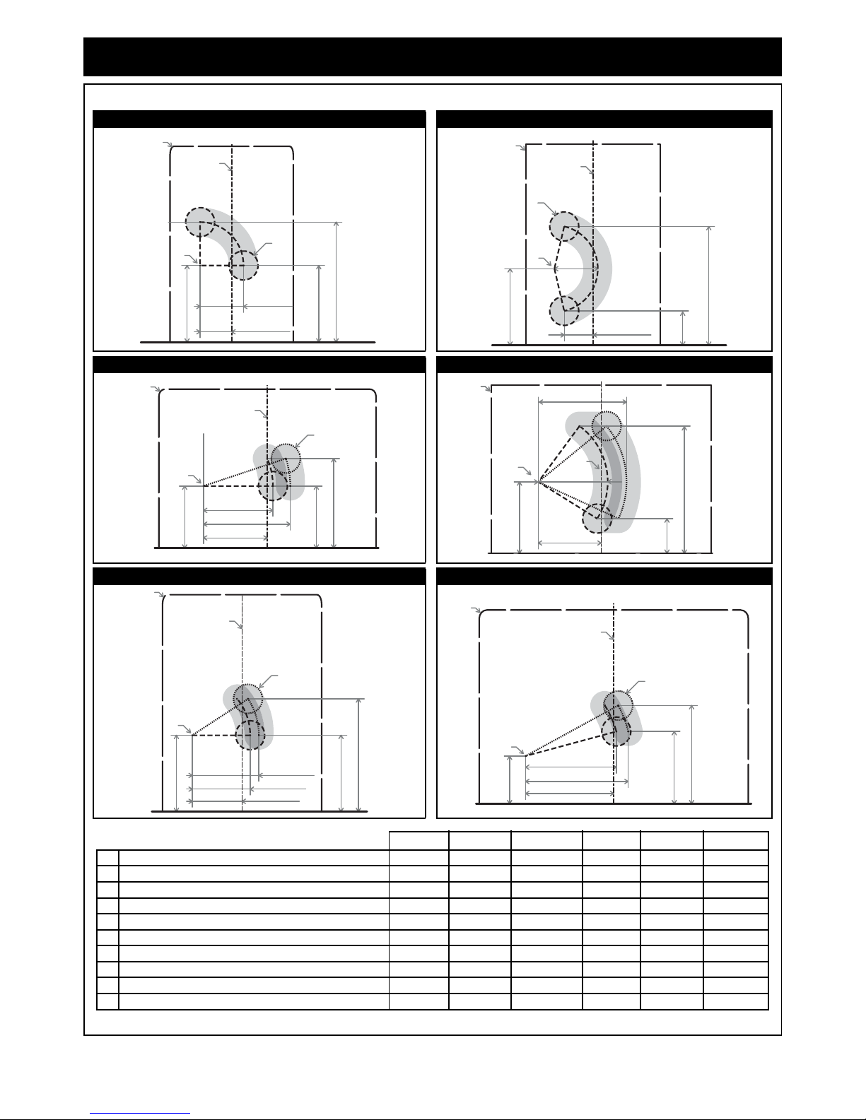
WALL PENETRATIONS
Below are diagrams and associated dimension tables for wall penetrations for each Energysaver heater model.
Table 1.
RHFE 308 RHFE 309
RHFE 556 RHFE 559
RHFE 557 RHFE 1004
All dimension are in millimetres
RHFE 308 RHFE 309 RHFE 556 RHFE 557 RHFE 559 RHFE 1004
i Width of appliance 426 465 750 550 760 930
ii Centre-Line of appliance 213 233 375 275 380 465
iii Arc axis (Axis point of the flue elbow) — — — — — —
A Horizontal distance from Centre-Line to arc centre 110 100 220 172 217 305
B Vertical distance from base to arc centre 265 265 215 264 247 165
C Minimum horizontal limit of arc 150 150 240 200 240 325
D Minimum vertical limit of arc 265 120 215 264 120 250
E Maximum vertical limit of arc 415 410 310 390 440 340
F Maximum horizontal limit of arc 150 150 300 230 305 365
G Penetration diameter 100 100 100 100 100 100
D
B
E
A
i
ii
G
C & F
iii
i
C & F
iii
ii
B
D
E
A
G
D
B
E
A
C
F
G
ii
I
iii
A
iI
ii
C
F
D
E
B
iii
D
B
E
A
C
F
G
ii
i
iii
D
B
E
A
F
C
G
ii
i
iii
 Loading...