

Rinnai RHFE1000, RHFE0800, RHFE1500 Installation Manual
Models: RHFE0800, RHFE1000, RHFE1500
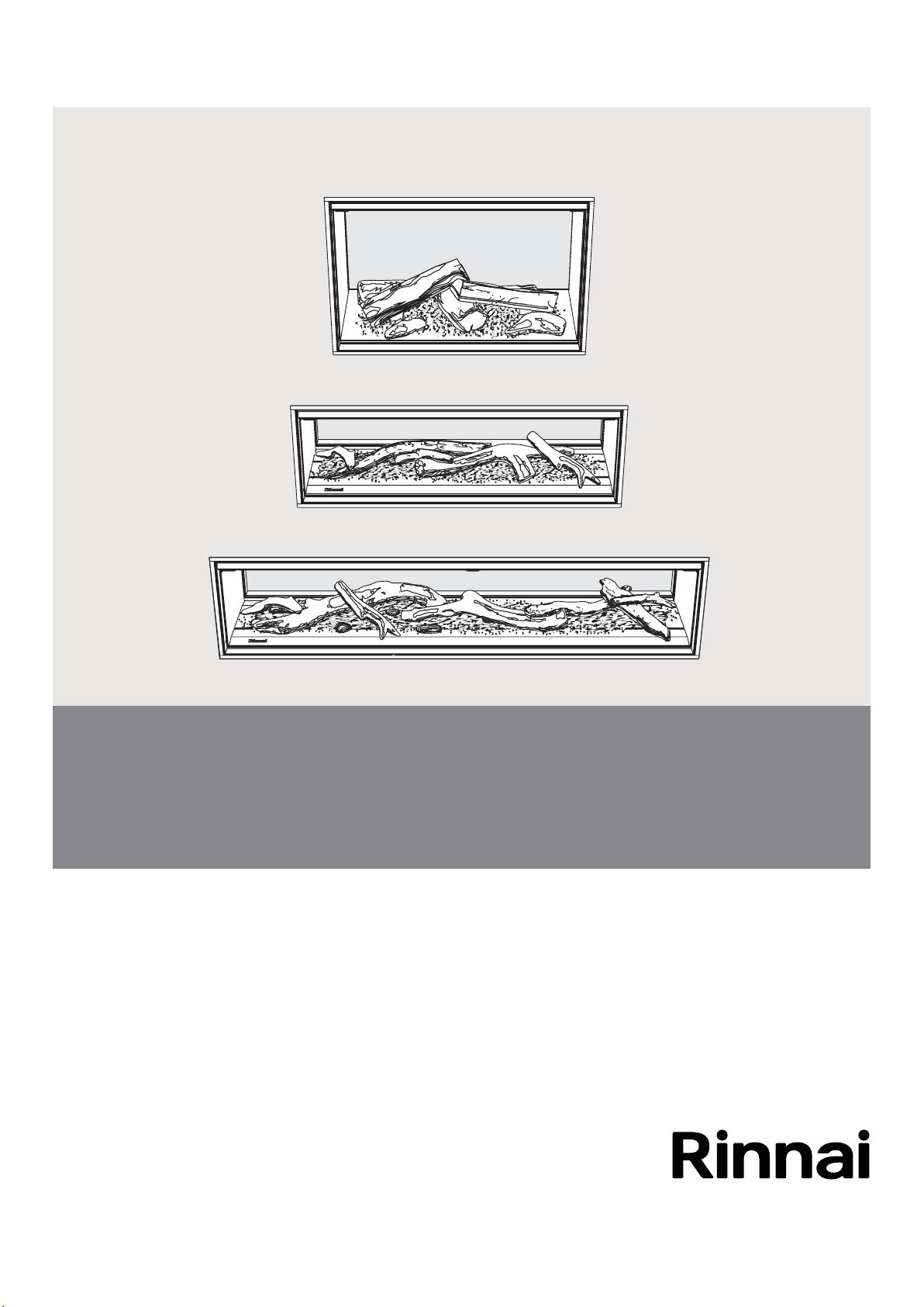
Linear collection gas fireplaces
Installation guide

Important
Appliance must be installed with a Rinnai approved ue
system.
This appliance shall be installed in accordance with:
- Manufacturer’s installation instructions
Current:
- AS/NZS 5601 Gas Installations
- AS/NZS 5263 Gas Appliances General Requirements
- AS/NZS 3000 Electrical Standards
- AS/NZS 3500 Plumbing and Drainage Standards
Installation, servicing and repair shall be carried out only by
authorised personnel.
Warning
Improper installation, adjustment, alteration, service or
maintenance can cause property damage, personal injury or
loss of life.
For more information about buying, using, and servicing of
Rinnai appliances call: 0800 RINNAI (0800 746 624).
Rinnai New Zealand Limited
105 Pavilion Drive, Mangere, Auckland
PO Box 53177, Auckland Airport, Auckland 2150
Phone: (09) 257 3800
Email: info@rinnai.co.nz
Web: www.rinnai.co.nz
www.youtube.com/rinnainz
www.facebook.com/rinnainz
Installer please note
When completing the installation it is ideal to have the homeowner present to test the Wi-Fi
connectivity and correct operation of the re.

Contents
Before you start ....................................................4
Specication .........................................................5
Unit dimensions (mm)...........................................6
Clearances from combustibles .............................7
Hearths .................................................................9
TV installation .......................................................10
Installation overview .............................................11
Cavity ventilation ..................................................12
Framing dimensions .............................................13
Gas supply............................................................17
Room thermistor ...................................................17
Electrical supply....................................................18
Flue terminal position ...........................................18
Installing the Linear into the cavity .......................19
Removing the glass front ......................................20
Commissioning .....................................................21
Wiring diagram .....................................................25
Burn media installation .........................................26
Test operation and lighting sequence ...................27
Check Wi-Fi connection........................................28
Installing the wall lining .........................................29
Flueing
General ueing guidelines ....................................36
Flueing options .....................................................38
Air hose connection ..............................................44
Linear ue components ........................................45
Before you start
H
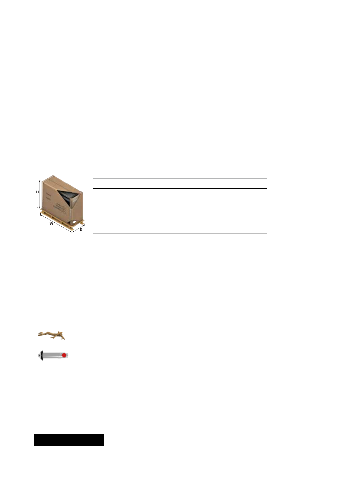
Unpack the appliance and components and check for damage. DO NOT install any damaged
items. Check all components have been supplied, refer table below, and that you have the
correct gas type.
Read these instructions to get an overview of the steps required before starting the installation.
Failure to follow these instructions could cause a malfunction of the appliance. This could result in
serious injury and/or property damage. There are also some sections in this guide that are crtical
to a successful installation, for example:
• Preline instructions regarding combustible and non-combustible materials
pages 7, 9, 29-35
• Cavity ventilation considerations page 12
• Framing dimensions in order to centre the glass of the re pages 13-16
Linear boxed dimensions
Linear 800 Linear 1000 Linear 1500
Height
Width
Depth
W
D
Weight
1156 mm
1350 mm
530 mm
120 kg
931 mm
1550 mm
530 mm
125 kg
931 mm
2050 mm
530 mm
140 kg
With the Linear engine comes the:
- Glass front
- Remote control (batteries included)
- Flue lock bracket and truss screws (x2)
- Operation and Installation guides
- Burn media installation guide
- Colour burn media placement sheet (attached to the glass frame)
- Commissioning sheet (in a plastic pouch inside the unit)
- Reducing are
- Linear 800 FlameTech or standard log set (inside the engine)
The burn media for the Linear 1000 and 1500 models will come packaged separately
in one large box.
Flue components and accessory items are ordered separately.
Installer please note
The Linear carton has a unit protection cutout that can be xed to the appliance to protect the
re from damage, debris, and dust, until nal commissioning can be completed.
4 | Linear installation guide 13563-H 08-19

Specication
Inbuilt power ued convection fan re operated by a simple infra-red remote, or by the Rinnai Wi-Fi
app that allows full thermostatic control as well as other features such as timers. Dierent burn media
options available.
Specication summary
Input Output* Heating area**
800 15-35 MJ/h 3.1-7.5 kW 70-120 m
800FT 15-35 MJ/h 3.1-7.7 kW 71-123 m
1000 14-34 MJ/h 3.1-7.4 kW 69-118 m
1500 14-40 MJ/h 3.1-8.5 kW 79-135 m
2
2
2
2
Eciency = > 75% (all models on high)
Gas type = NG or ULPG
* Will vary according to gas type and ue conguration
** Will vary depending on geographical location in NZ
Suitability
Ideal for living rooms and open plan areas.
Versatile power ue system makes for easy
installation in almost any living space, including
bedrooms.
The Linear is ideal for a new build installation.
Installation considerations
Room size—smaller rooms will heat up quickly,
and due to the eciency of the appliance, if in
thermostatic mode, will reduce to a low ame
prole.
Installation of the Linear higher up the wall, in
some room congurations, can create draughts
due the convection air being pushed out from
the top of the appliance.
For more accurate room temperature control
and to prevent heat build-up inside the cavity,
it is strongly recommended to ventilate the
replace enclosure. Refer p.12 for more
information.
Convection fan
2-speed fan. Heat is distributed from the top of
the appliance.
800/1000
Base of the combustion chamber, LHS, on the
convection fan access panel.
Gas connection
½ “ BSP, the gas supply terminates inside the
unit—lower left hand side of the appliance.
Ignition: Continuous spark electronic ignition.
Noise level: 37-45 dB(A)
Power ue
Inner 50 mm, outer 70~80 mm. Appliance must
be installed with a Rinnai ue system.
Power consumption/electrical supply
High = 50 W
Standby = <8 W
The Linear has a 1.5 m power cord with a three
pin plug supplied. The power cord passes
through a slot in the right hand side of the
appliance.
Safety devices
Flame failure sensing system, pressure relief,
overheat safety switch, air temperature sensor,
thermal fuse, overcurrent fuse, and spark
detection.
Temperature control
The Linear can be operated using the basic
infra-red remote, or for more features, such as
timers and thermostatic control, using Rinnai’s
Wi-Fi replace controller app.
Weights
Unit Packaged
800 100 kg 120 kg
Data plate
1500
Base of the combustion chamber towards the
LHS, between the gas control and convection
fan access panel.
1000 100 kg 125 kg
1500 110 kg 140 kg
Linear installation guide 13563-H 08-19 | 5
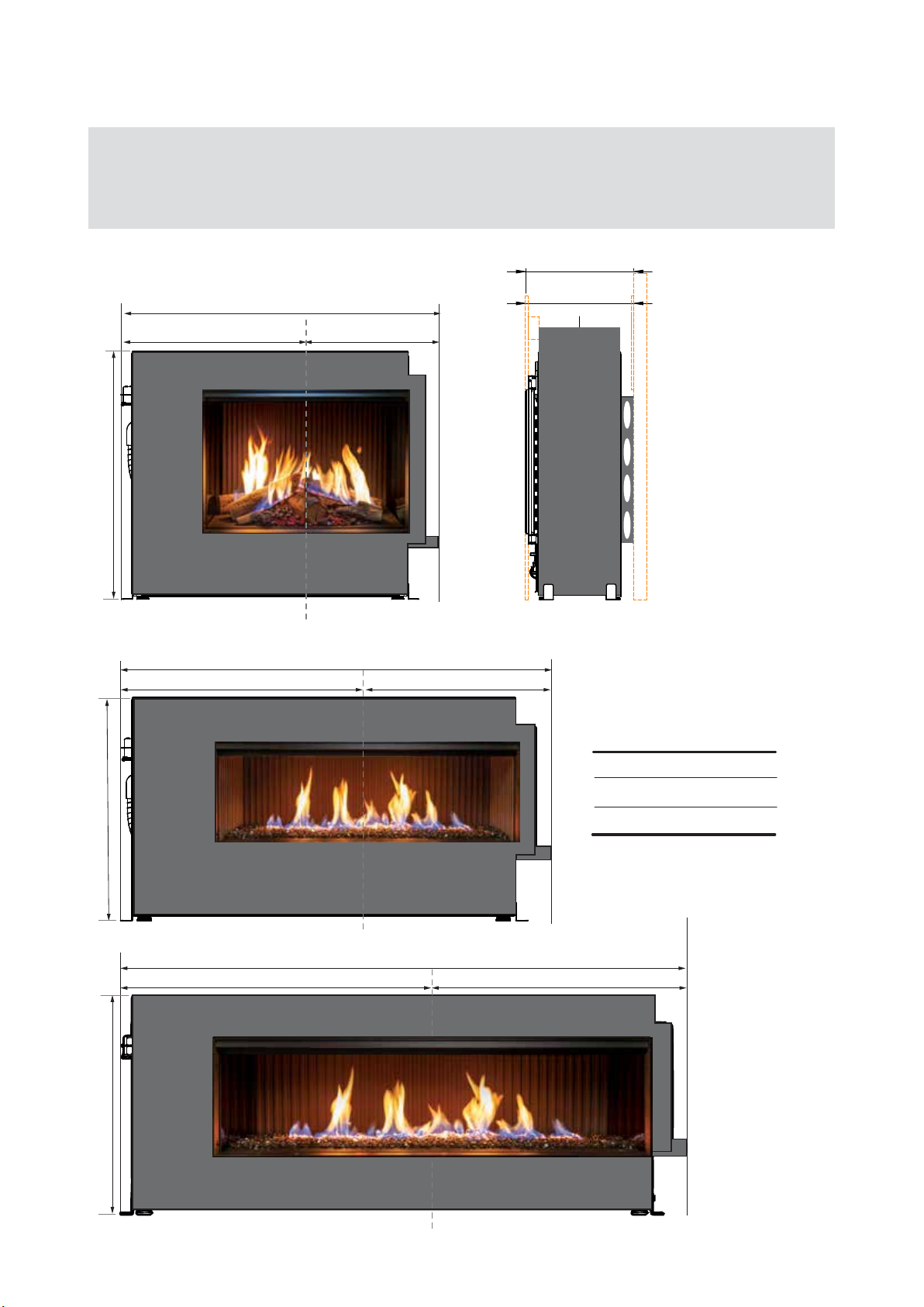
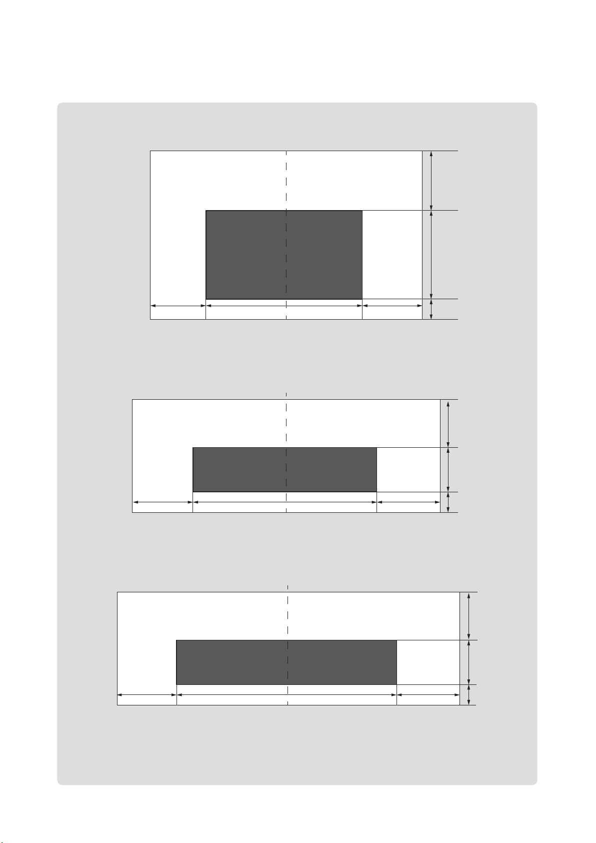
Unit dimensions (mm)
IMPORTANT
• These are the unit dimensions only, not the framing/cavity dimensions, refer p.14-16
• The centre of the glass is NOT the centre of the appliance
• Depth dimension is the same for all models
425 min.
singled sided
425 face-to-face
1245 mm
726 mm 519 mm
966 ± 5 mm
double sided
Adjustable feet on all models
Glass centreline
741 ± 5 mm
Glass centreline
1435 mm
816 mm 619 mm
Glass centreline
1935 mm
1066 mm
Glass dimensions
800 800 x 505 mm
1000 1000 x 280 mm
1500 1500 x 280 mm
869 mm
741 ± 5 mm
6 | Linear installation guide 13563-H 08-19
Glass centreline
Clearances from combustibles
B - mantel depth
The clearances listed below, measured from the edge of the glass, are minimum
clearances unless otherwise stated.
While the heater is operating
The appliance must not be installed where
curtains or other combustible materials could
come into contact with the re. The 400 mm side
clearance includes side walls. The 1000 mm
clearance is in front of the re.
Floor protection
Heat emanating from this re may over time
aect the appearance of some materials used
for ooring, such as, carpet, vinyl, cork or timber.
This may be amplied if the air contains cooking
vapours or cigarette smoke. To avoid this
occurring, it is recommended that a mat be placed
in front of the appliance.
Mantels and surrounds
Combustible mantels and surrounds require
clearance from the unit to minimise the risk of
re.
1000 mm
400 mm
400 mm400 mm
A
Mantels and surrounds, made of combustible
material such as wood are allowed providing
C
they are outside the minimum clearances shown
below.
A Mantel needs to be a minimum of 400 mm away from the edge of the glass
B Maximum mantel depth at 400 mm (A) is 250 mm maximum
C Surround needs to be a minimum of 400 mm away from the edge of the glass
For every 50 mm of added mantel depth there must be an additional 100 mm of clearance from the
edge of the glass. For example:
Mantel depth A: clearance required
300 mm 500 mm
350 mm 600 mm
400 mm 700 mm
Linear installation guide 13563-H 08-19 | 7
The below diagrams are to assist in determining the full clearance area around the
Linear.
1600
400
Clearance
1157-1167
505
Glass height
Linear 800Linear 1000Linear 1500
257 ± 5*
400
Clearance
800
Glass width
400
Clearance
* Adjustable
firebox feet
932-942
Clearance
932-942
400
1800
1000
Glass width
2300
400
Clearance
400
Clearance
280
Glass
height
257 ± 5*
* Adjustable
firebox feet
400
280
Clearance
Glass
height
400
Clearance
8 | Linear installation guide 13563-H 08-19
1500
Glass width
400
Clearance
257 ± 5*
* Adjustable
firebox feet
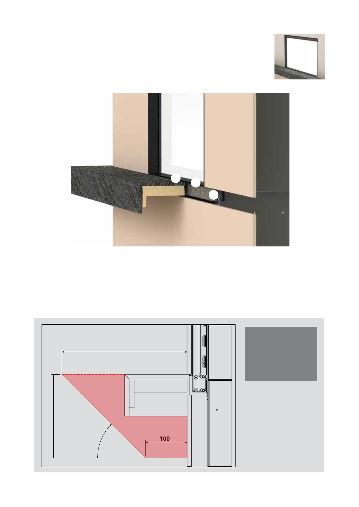
Hearths
Any hearth that is installed in the shaded area (shown below) must
be capable of withstanding temperatures up to 100 °C. Some
laminated materials may buckle or delaminate when exposed to
high levels of heat.
1
3
2
1. A 3 mm air gap between the hearth and lower re lip is critical. This allows for air ow to critical
components and for correct operation of the IR receiver.
2. The lower support rail is only required if the side rails are used, side rails are required for
combustible wall linings.
3. The nishing trims latches are not needed if a hearth is installed, they can be snapped o if
they are in the way.
Please note:
Shaded area
300
must be capable
of withstanding
temperatures up to
100 °C.
200
45°
100
Linear installation guide 13563-H 08-19 | 9
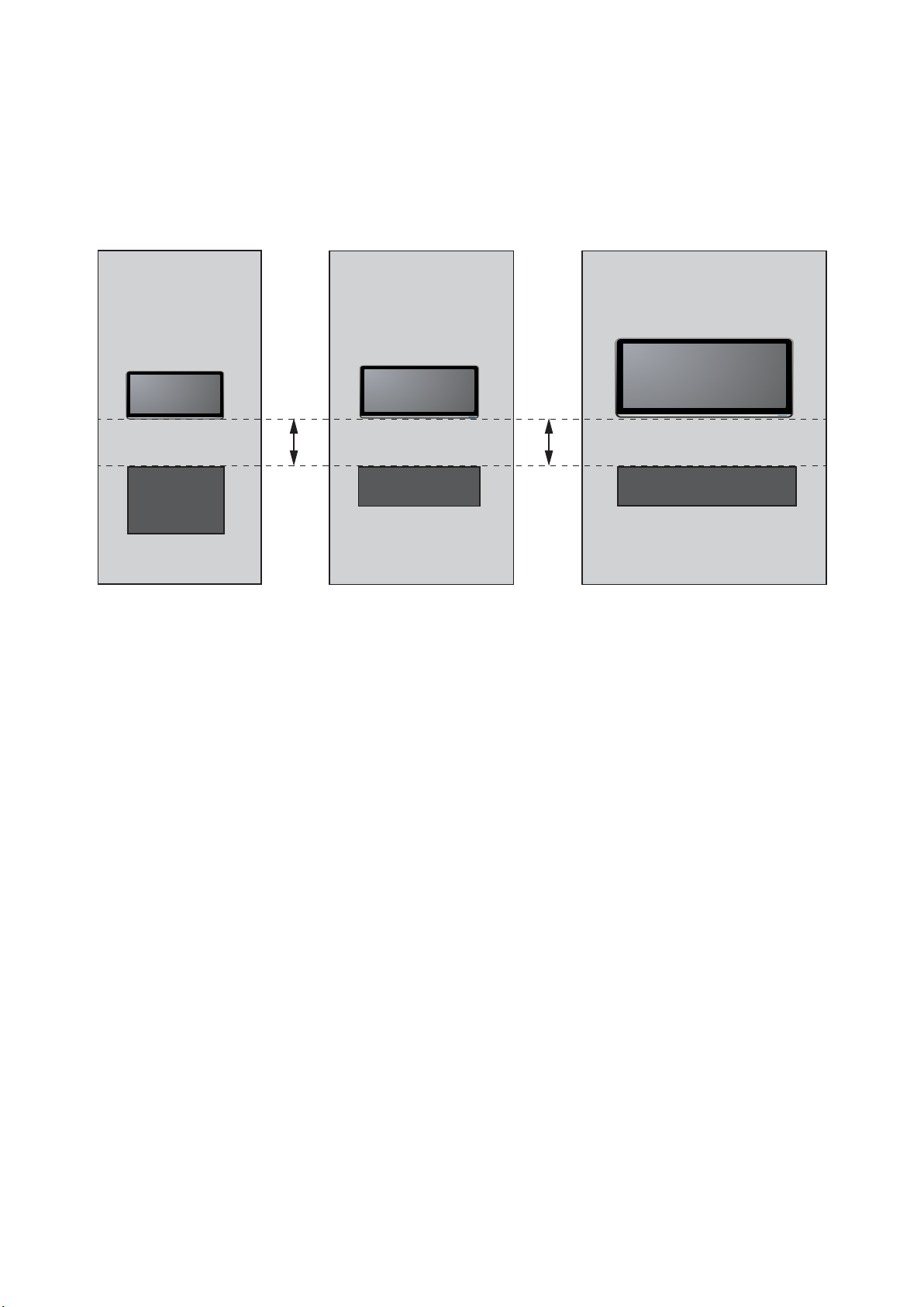
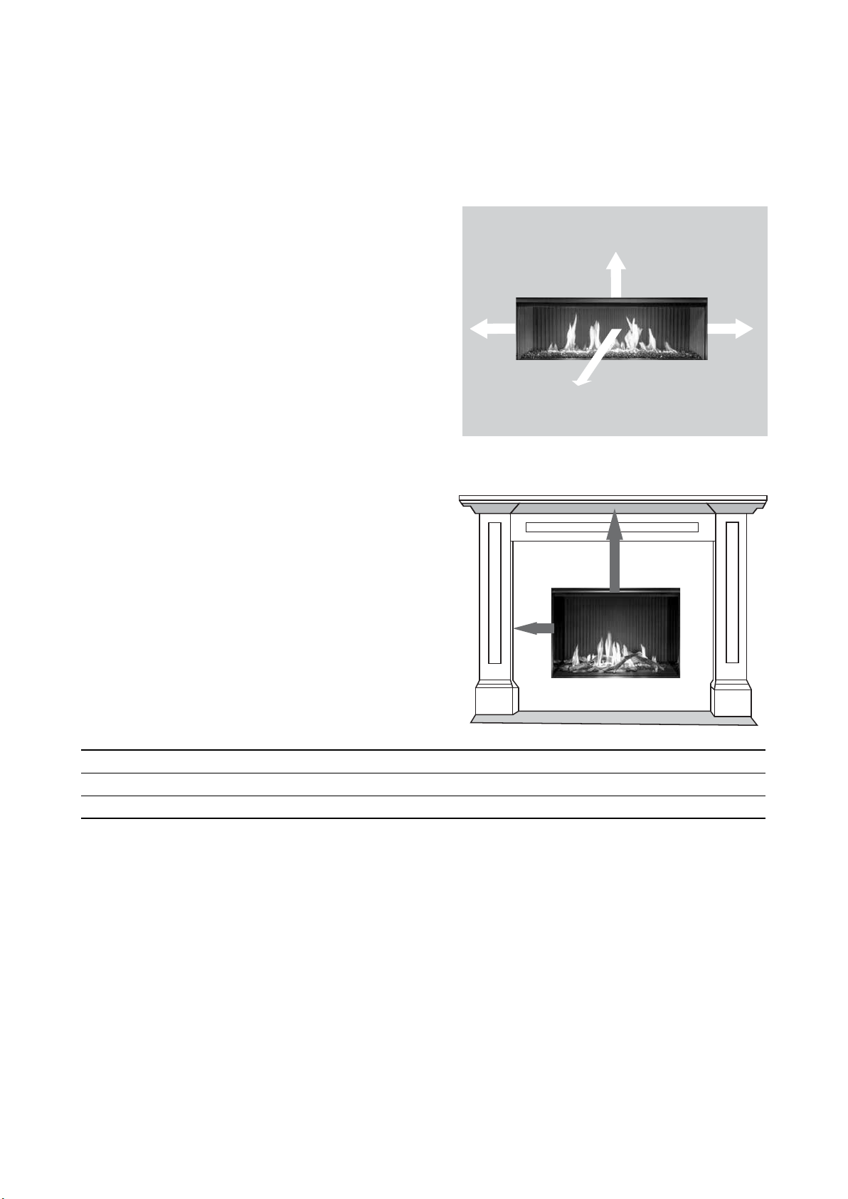
TV installation
The Linear has a fan that distributes warm air from the top of the appliance out into
the room. As warm air is dispersed outwards and not directly upwards, installation
of a TV may be an option.
400 mm 400 mm
The diagram shows recommended clearances when installing a TV directly above the Linear, or
into a recess. All dimensions are in millimetres.
Always check with the TV manufacturer
It is up to the owner to check the TV installation with the TV manufacturer—some have warranty
conditions that state a TV is not to be installed above a replace.
Rinnai does not accept any responsibility for damage to a TV resulting from the use of this
information.
10 | Linear installation guide 13563-H 08-19

Installation overview
Complete framing and base panel, p.12-16.
Prepare gas and electrical connections, and cavity ventilation.
Fit the Linear
Move the Linear into the cavity. Tip forward slightly to get the two back feet in rst. To reduce the
weight you can remove the glass rst (p.20). The Linear as adjustable feet on all corners. Use these
feet to level the re. This is critical so the wall lining can be installed ush to the lips of the re. Once
level, secure the Linear to the base of the enclosure using the four brackets, which also act as
seismic restraints (p.19).
Complete the gas connection
To access the gas connection and gas control, remove the screws holding the Wi-Fi panel in place
(refer image on p.28 for Wi-Fi assembly position). At this stage also check the ue conguration to
see if a dip switch change is required. Check for gas leaks.
Fit the ue, refer p.36-47 for more information.
Commission with the glass o
Follow the commissioning instructions, p. 21-24.
Install the burn media
Placement of the burn media is critical to the performance and safe operation of the appliance. Refer
p.26 for more information.
New build
Install the glass front
Reinstall the glass front, check operation of the re, check the remote and Wi-Fi module is working
(p.28).
Complete nal framing and install the wall lining
Complete the nal framing once you are satised the re is working correctly—there will be limited
access to the unit once nal framing is completed.
Install the wall lining as one piece (so it doesn’t crack), with a cutout for the glass, up to the lips of
the unit. DO NOT go over the lips. There is an air gap of at least 3 mm around the lips of the re,
which is CRITICAL to safe operation, to ensure air ow in and around the unit.
Fix the wall lining in place. We recommend gluing as screws will transfer heat, and during installation
there is the potential to damage some controls of the re if screws are used, refer p. 29-35 for more
information.
N.B: For new builds the nal stage could be completed prior to commissioning.
Helpful tips
To level the unit and not aect where the feet go, the seismic brackets need to be elevated
once the unit is o the pallet.
We STRONGLY recommend the gas is on to check the inlet pressure as access to controls
after the wall lining is on is more dicult.
Linear installation guide 13563-H 08-19 | 11
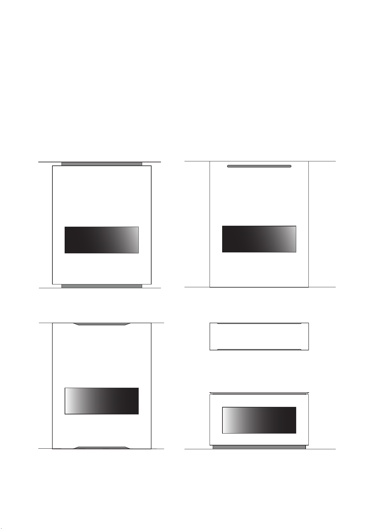
front view front view
Cavity ventilation
Ventilation of at least 2000 mm2 is recommended in the cavity, ideally below the base of the re.
This
is to provide room air at ambient room temperature to the re thermistor located in the base of the
1
. Ventilation can be via a vent or an open toe kick at the base of the cavity—it must be in the
re
same room as the re.
Additionally the top of the cavity needs to be ventilated into the room or another space. This
2.
ventilation opening must also be at least 2000 mm
This opening prevents heat build up inside the
cavity, which if left unvented could cause damage to wall surfaces or coverings and/or cause the
re to cut out.
Cavity ventilation design ideas
front view peninsular top view
peninsular side view
1
Alternatively provide a way of moving the room temperature thermistor into the room, for example under the hearth—ensure it can be
accessed/removed for service.
12 | Linear installation guide 13563-H 08-19
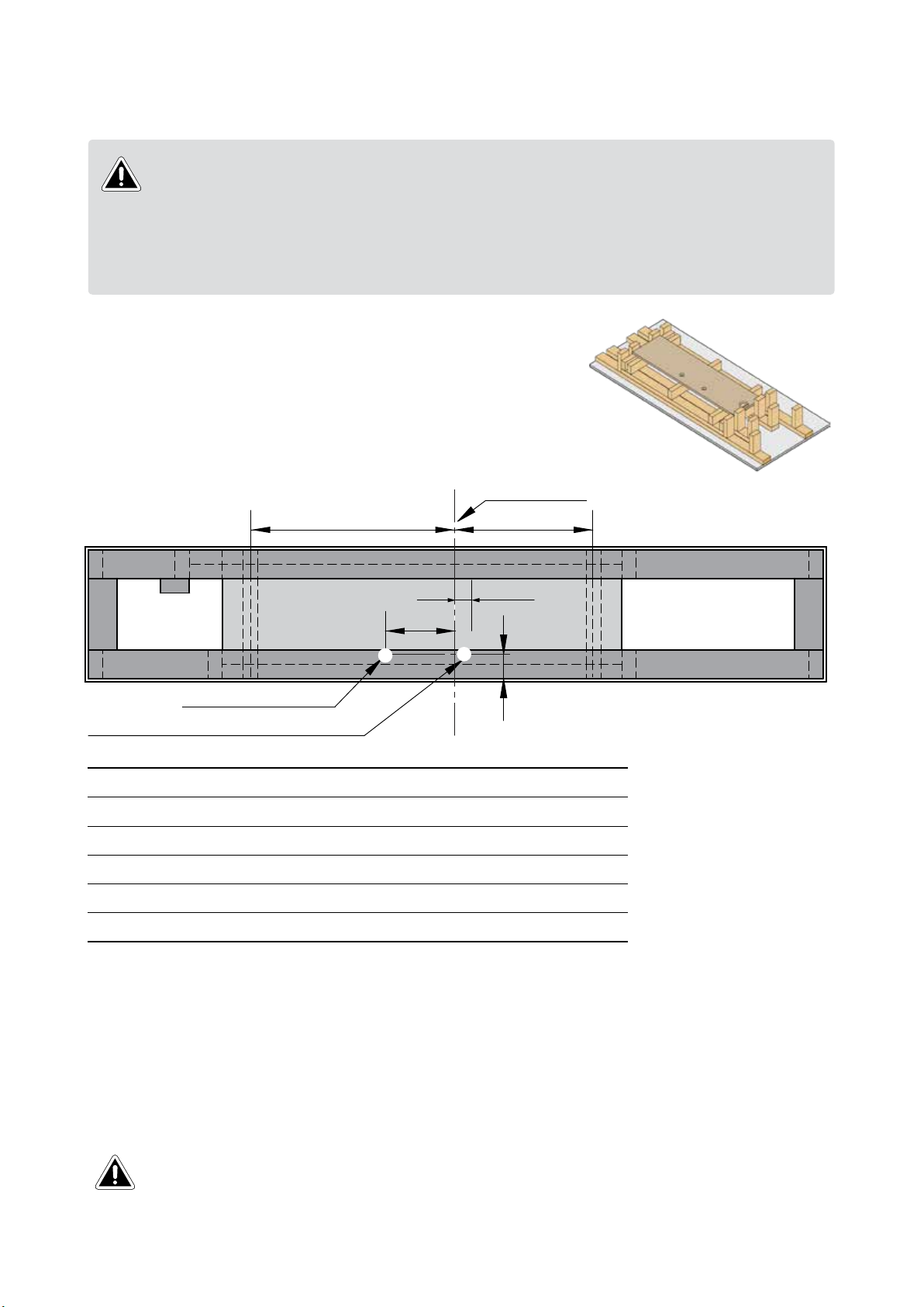
Framing dimensions
The framing dimensions have the studs oset. This is because the cavity needs to be
IMPORTANT
Base board and connection cutouts
To ensure everything lines up and ts properly it’s recommended
that on the base the following dimensions are pencilled; glass
centreline, unit depth centreline, feet position, gas and room
thermistor cutouts.
framed based on the centreline of the Linear glass, NOT the opening size.
Where there is a requirement for a symmetrical installation, the cavity size will need to
increase. To calculate a rough opening width, double the ue to centreline gure on the
following pages.
Glass centreline
C D
A
B
Gas supply access
Thermistor / room supply air Ø 40 mm
Linear 800 Linear 1000 Linear 1500
A (room supply air) 50 mm 50 mm 255 mm
B (gas supply) 220 mm 220 mm 220 mm
C (support feet centres) 640 mm 740 mm 990 mm
D (support feet centres) 360 mm 460 mm 710 mm
E* (from front of cavity) 77 mm 77 mm 77 mm
* E asssumes 10 mm wall board
E
Additional framing notes
• Wallboard is set 1 mm back from the front edge of the lips to allow for a slim edge plaster nish.
• To ensure the appliance performs correctly, without rattling, the Linear MUST BE installed on
a at level support base. The joists must be capable of supporting a minimum of 1.5 times the
weight of the appliance—base panel is also designed to take the weight of the wallboard.
Issues caused by rattling res not installed on a at level base, as detailed in this guide,
IMPORTANT
will not be covered by warranty.
Linear installation guide 13563-H 08-19 | 13
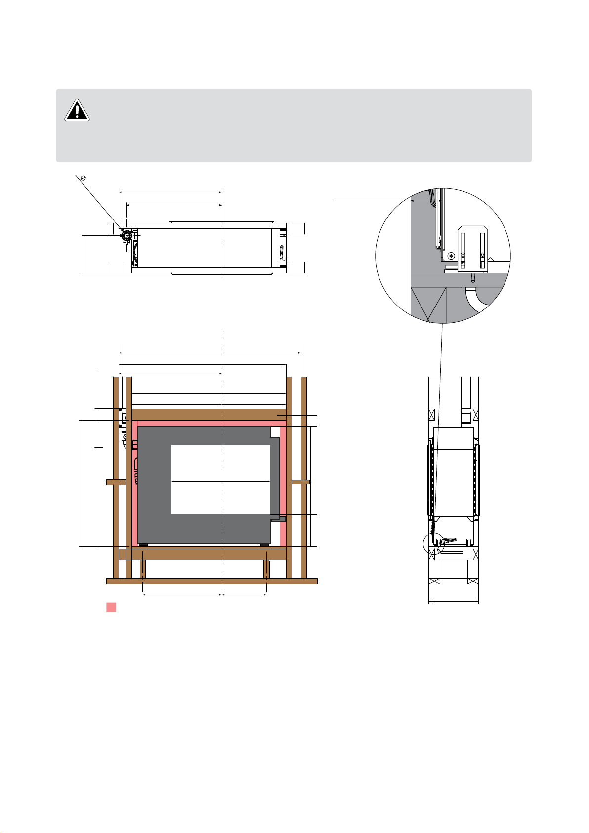
Linear 800 minimum framing dimensions (mm)
The framing dimensions have the studs oset. This is because the cavity needs to be
framed based on the centreline of the Linear glass, NOT the opening size.
IMPORTANT
Where there is a requirement for a symmetrical installation, the cavity size will need to
increase, refer diagram below.
80**
Front face to
center of flue
300
500 **
845
770
Glass centreline
1690 (for symmetrical cavity)
1365
845
1250
Clearance (approx. 50 mm)
39 assumes
10 mm wallboard
520 730
Recommend that the lintel is left
until the fire is installed so min.
clearances can be maintained
816*
1020 min.
~800
257±5* 566*
640 360
Shaded area denotes a clearance around the fire of approx. 50 mm.
On the RHS this is automatically achieved with the carry bar.
403 mm assumes a 10 mm wallboard
on both sides of a double-sided unit.
415 mm is the min. for a single-sided
unit to maintain 50 mm clearance to
the back of the fire.
* Minimum wallboard cutout, refer table on p.29
** Maintain 25 mm clearance to combustibles for the rst 500 mm of ue
• All dimensions are assuming a 10 mm wallboard
• Studs and joist are required directly below the support feet of the re
• Framing shown is 90 x 45 mm
• Fire platform shown is 18 mm plywood
• Allow room underneath the appliance for the gas supply to enter the re cavity (min. 100 mm)
403
14 | Linear installation guide 13563-H 08-19
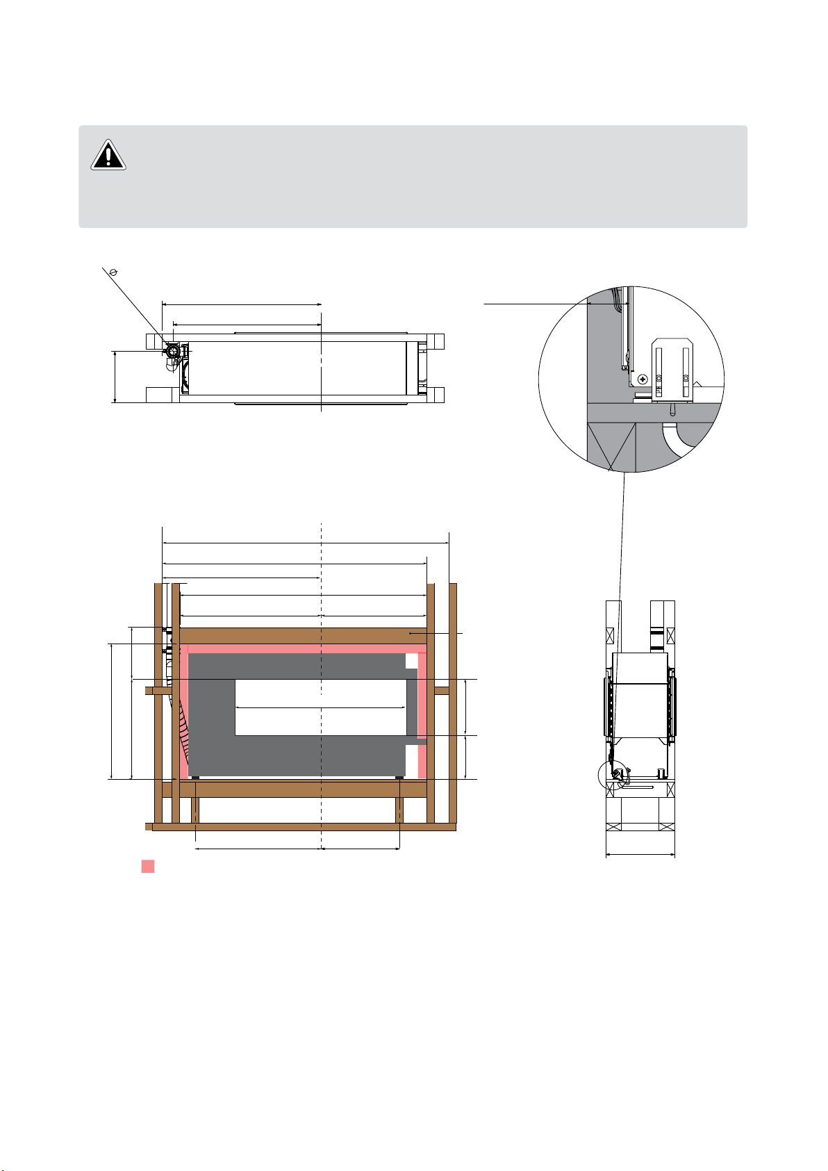
Linear 1000 minimum framing dimensions (mm)
The framing dimensions have the studs oset. This is because the cavity needs to be
framed based on the centreline of the Linear glass, NOT the opening size.
IMPORTANT
Where there is a requirement for a symmetrical installation, the cavity size will need to
increase, refer diagram below.
80**
Front face to
center of flue
300
945
870
39 assumes
10 mm wallboard
500 **
796 min
~ 575
Glass centreline
1890 (for symmetrical cavity)
1565
945
1450
620 830
Clearance (approx. 50 mm)
1016*
740 460
Shaded area denotes a clearance around the fire of approx. 50 mm.
On the RHS this is automatically achieved with the carry bar.
Recommend that the lintel is left
until the fire is installed so min.
clearances can be maintained
257±5* 341*
403 mm assumes a 10 mm wallboard
on both sides of a double-sided unit.
415 mm is the min. for a single-sided
unit to maintain 50 mm clearance to
the back of the fire.
403
* Minimum wallboard cutout, refer table on p.29
** Maintain 25 mm clearance to combustibles for the rst 500 mm of ue
• All dimensions are assuming a 10 mm wallboard
• Studs and joist are required directly below the support feet of the re
• Framing shown is 90 x 45 mm
• Fire platform shown is 18 mm plywood
• Allow room underneath the appliance for the gas supply to enter the re cavity (min. 100 mm)
Linear installation guide 13563-H 08-19 | 15
 Loading...