

Rinnai Galley series, Grand Monaco series, Buffet series, Grand Cafe series, Grand Gourmet series Operating & Assembly Instruction
Page 1
These instructions are a guide
to assembling and using
the propane and natural gas
versions of the Rinnai Outdoor
Kitchen range: Galley, Buffet,
Grand Café, Grand Gourmet
& Grand Monaco models.
Please read carefully, and
retain for future reference.
All reference to propane applies to LPG
in New Zealand.
Only to be used outdoors.
Illustration may vary from barbecue
contained in carton.
Customers operating & assembly instructions
PART NO. 8417100
FOR YOUR SAFETY
.
1. Do not store or use
gasoline or other flammable
vapours and liquids in the
vicinity of this or any other
appliance.
2. An LP-gas cylinder not
connected for use shall not
be stored in the vicinity of
this or any other appliance.
FOR YOUR SAFETY
.
IF YOU SMELL GAS:
1. Shut off gas to the appliance.
2. Extinguish any open flame.
3. Open lid or hood.
4. If odour continues,
immediately call your gas
supplier or fire department.
Page 2
CONGRATULATIONS!
You have just purchased a state of the art Rinnai Modular Kitchen Cooking System.
At Rinnai, we understand your desire to protect an investment of this nature.
As such this booklet has been designed to assist you in the assembling, testing and operating
your new barbecue, along with important safety information, helpful maintenance tips
and troubleshooting.
We thank you for choosing Rinnai and trust that you enjoy years of outdoor entertainment
with our product.
Happy Gourmet cooking!
QUICK FIND INDEX
SAFETY INFORMATION
Hose and regulator safety 3
Locating your barbecue 4
Checking for gas leaks 4
Propane cylinders 4
ASSEMBLY
What tools you need 5
List of your barbecue’s contents 6~7
Assembly of trolley 8~14
Connecting to gas source 15
Burner operation and ignition system check 15
Installation of side burner gas piping connection 16
Cooker component installation 17
Temperature gauge 17
OPERATION
Lighting procedure - main barbecue 18
Operation procedure 18
Lighting procedure - side burner 19
Cooking with hood down 19
Rotisserie cooking 20
Failure check procedures 21
MAINTENANCE
General cleaning 22
Annual cleaning 23
RINNAI GUARANTEE OF QUALITY
Storage 23
Guarantee 24
Rinnai branches 24
CONGRATULATIONS!
You have just purchased a state of the art Rinnai Outdoor Kitchen Cooking System.
At Rinnai, we understand your desire to protect an investment of this nature. As such this booklet has been
designed to assist you in the assembling, testing and operating your new barbecue, along with important safety
information, helpful maintenance tips and troubleshooting. We thank you for choosing Rinnai and trust that you
enjoy years of outdoor entertainment with our product.
Happy Gourmet cooking!
Note: All reference relating to the Rinnai Outdoor Kitchen GRAND GOURMET model is applicable to Australia ONLY.
For New Zealand, this model is distributed as the MAX model.
CONTENTS
2
2
Page 3
Minimum clearances from combustible materials must
be: Rear - 800 mm (32"). Sides - 300 mm (12").
CLEARANCES
Height – Hood closed 1140 mm. Hood open 1530 mm
Width – 1650 mm
(including trolley)
Depth – 575 mm
OVERALL DIMENSIONS
Appliance specifications can be found on the data
label attached to the fascia of the barbecue.
SPECIFICATIONS
Australian Gas Association Certificate No. 5881.
Barbecues must be used in accordance with the
installation requirements of your local gas supply
authority, or the appropriate installation code issued
by the Australian Gas Association and the Australian
Liquified Petroleum Gas Association.
Barbecues for use with bottled gas are labelled
‘Propane Gas’. Barbecues for use with natural gas are
labelled
‘Natural Gas’ and must be installed by an
authorised person. Check the gas type sticker attached
to the barbecue. Check that the label matches the gas
type for the area in which it is to be installed.
GAS INSTALLATION CODES
The regulator and hose assembly supplied with the
barbecue are suitable for liquified petroleum gas (LPG).
A gas regulator adjusted to have an outlet pressure
of 2.75 kPa is supplied for connection to the LP gas
cylinder. The pressure regulator and hose assembly
supplied with the appliance must be used.
Replacement pressure regulators and hose assemblies
must be those specified by the appliance manufacturer.
When connecting the hose and regulator assembly
to the gas cylinder, take care to avoid unnecessary
twisting of the flexible hose. After the assembly has
been secured, turn on the gas and check for leaks by
brushing a soap and water solution over all connections.
The presence of bubbles will indicate a gas escape.
DO NOT TEST FOR GAS ESCAPES WITH AN
OPEN FLAME
(Match, lighter etc).
If you are unable to correct the leak by tightening
the connections, turn off the gas and contact the Rinnai
immediately.
Always ensure the appliance is kept away from
flammable materials and the gas cylinder clear of any
heat source.
When changing over from an empty gas cylinder
to a full one, make sure this procedure is carried out in
a flame free atmosphere.
Inspect the gas hose when replacing the gas
cylinder or once a year whichever is more frequent. If
the hose is cracked, cut, abraded or damaged in any
way, the appliance must not be operated. The hose
must be replaced if damaged and when statutory
conditions require it. Contact Rinnai if uncertain.
The hose and regulator should be disconnected
from the cylinder when the outdoor appliance is not in
use.
HOSE AND REGULATOR SAFETY
NEVER OPERATE THIS BARBECUE
WITHOUT A REGULATOR.
!
FAILURE TO COMPLY WITH THESE
INSTRUCTIONS COULD RESULT IN A
FIRE OR EXPLOSION WHICH COULD
CAUSE SERIOUS BODILY INJURY,
DEATH OR PROPERTY DAMAGE.
!
ACCESSIBLE PARTS MAY BE
VERY HOT.
KEEP YOUNG CHILDREN AWAY.
ANY MODIFICATION OF THIS
APPLIANCE MAY BE DANGEROUS.
DO NOT MOVE THIS APPLIANCE
DURING USE.
TURN OFF THE GAS SUPPLY AT THE
GAS CYLINDER AFTER USE.
READ THE INSTRUCTIONS BEFORE
USING THE APPLIANCE.
PARTS SEALED BY THE
MANUFACTURER OR THEIR AGENT
MUST NOT BE MANIPULATED BY
THE USER.
THIS BARBECUE IS ONLY TO BE
USED AND STORED OUTDOORS.
!
IF THIS INFORMATION IS NOT
FOLLOWED EXACTLY, A FIRE
CAUSING DEATH OR SERIOUS INJURY
MAY OCCUR!
DO NOT STORE A SPARE LP-GAS
CYLINDER UNDER OR NEAR THIS
APPLIANCE.
NEVER FILL THE CYLINDER BEYOND
80% FULL.
THIS BARBECUE IS ONLY TO BE
USED OUTDOORS.
FOLLOW STORAGE INSTRUCTIONS
WHEN NOT IN USE.
!
GENERAL INFORMATION
3
3
Page 4
FOR YOUR SAFETY...
DO NOT STORE OR USE PETROL OR
OTHER FLAMMABLE VAPOURS AND
LIQUIDS IN THE VICINITY OF THIS OR
ANY OTHER APPLIANCE.
DO NOT STORE EMPTY OR FULL SPARE
GAS CYLINDERS UNDER OR NEAR THIS
OR ANY OTHER APPLIANCE.
KEEP THE GAS HOSE AND ANY
ELECTRICAL CORD AWAY FROM HOT
SURFACES. PROTECT GAS HOSE FROM
DRIPPING GREASE. AVOID
UNNECESSARY TWISTING OF HOSE.
VISUALLY INSPECT HOSE PRIOR TO
EACH USE FOR CUTS, CRACKS,
EXCESSIVE WEAR OR OTHER DAMAGE.
REPLACE HOSE, IF NECESSARY.
NEVER TEST FOR GAS LEAKS WITH A
LIT MATCH OR OPEN FLAME.
NEVER LIGHT BARBECUE WITH HOOD
CLOSED OR BEFORE CHECKING TO
ENSURE BURNER TUBES ARE FULLY
SEATED OVER GAS VALVE ORIFICES.
NEVER LEAN OVER COOKING
SURFACE WHILE LIGHTING BARBECUE.
USE GOOD QUALITY INSULATED
OVEN MITTS WHEN HANDLING
BARBECUE TOOLS.
NEVER ALTER OR MODIFY THE
REGULATOR OR GAS SUPPLY ASSEMBLY.
THIS BARBECUE MUST NOT BE USED
INDOORS.
!
SAFETY
4
4
DANGER: IF YOU SMELL OR HEAR
THE HISS OF ESCAPING GAS FROM
THE PROPANE GAS CYLINDER:
KEEP CLEAR OF THE PROPANE GAS
CYLINDER.
DO NOT ATTEMPT TO CORRECT THE
PROBLEM YOURSELF.
CALL YOUR FIRE DEPARTMENT
(DO NOT MAKE THE CALL FROM
ANYWHERE NEAR THE PROPANE GAS
CYLINDER - YOUR TELEPHONE IS AN
ELECTRICAL DEVICE, AND COULD
PRODUCE A SPARK).
YOUR BARBECUE IS PRESET AT THE
FACTORY TO OPERATE ON PROPANE
GAS ONLY, UNLESS SPECIFIED
OTHERWISE.
!
IF YOU SMELL GAS:
1. SHUT OFF GAS TO THE APPLIANCE
AT ITS SOURCE, IF POSSIBLE.
2. EXTINGUISH ANY OPEN FLAME.
3. OPEN HOOD.
4. IF ODOUR CONTINUES, IMMEDIATELY
CALL YOUR GAS SUPPLIER OR FIRE
DEPARTMENT.
!
READ CAREFULLY BEFORE
ASSEMBLING AND OPERATING
YOUR BARBECUE.
!
NEVER CONNECT AN UNREGULATED
PROPANE GAS CYLINDER TO YOUR
BARBECUE.
!
NEVER STORE YOUR PROPANE GAS
CYLINDER INDOORS
!
DO NOT use your barbecue in garages, porches,
breezeways, sheds or other enclosed areas. Your barbecue is to be used OUTDOORS ONLY. The barbecue is not
intended to be installed in or on recreational vehicles
and/or boats and should not be placed under any surface
that will burn. Do not obstruct the flow of combustion
and ventilation air around the barbecue housing.
LOCATION OF YOUR BARBECUE
Keep children away from barbecue during use and
until barbecue has cooled after you are finished. Do not
allow children to operate barbecue.
PROTECT CHILDREN
NEVER TEST FOR LEAKS WITH A FLAME
Prior to first use, and at the beginning of each new
season
(or, if using propane, whenever gas cylinder is
changed)
, it is a must for you to check for gas leaks.
Follow these steps:
1. Make soap solution by mixing one part liquid detergent and one part water.
2. Turn burner control(s) to
‘OFF’, then turn on gas at
source.
3. Apply the soap solution to all gas connections.
Bubbles will appear in the soap solution if connections are not properly sealed. Tighten or repair as
necessary.
4. If you have a gas leak you cannot repair, turn off the
gas at the source, disconnect hose from barbecue
and immediately call Rinnai/Rinnai supplier for
professional assistance.
CHECKING FOR GAS LEAKS
The propane gas cylinder should be filled by a
reputable propane gas dealer, and visually inspected and
re-qualified at each filling.
Always keep cylinder in an upright position.
Always close the cylinder valve when the barbecue is not
in use.
Do not subject propane gas cylinder to excessive heat.
If you store your barbecue indoors, ALWAYS
disconnect propane gas cylinder FIRST, and store
propane gas cylinder safely outside. Cylinders must be
stored outdoors in a well ventilated area out of reach of
children, and must not be stored in a building, garage or
any other enclosed area.
This is a low pressure barbecue and must only be
used with the hose and regulator supplied.
Your barbecue is designed for use with 4.5 kg or 9 kg
PROPANE gas cylinder. DO NOT CONNECT YOUR
BARBECUE TO A PROPANE GAS CYLINDER
EXCEEDING THIS CAPACITY.
PROPANE GAS CYLINDER USE & SAFETY
Page 5
Before attempting to assemble your barbecue, it
is advisable to check that all the necessary parts have
been included using the parts list on the following
pages. Inspect barbecue and trolley parts as you proceed.
Contact Rinnai dealer for assistance regarding
replacement of any damaged or missing parts.
Do not assemble or operate a barbecue that
appears damaged.
Check that the barbecue supplied is correct for
the gas type being used. There is a label on the side
panel of the barbecue above the gas connection.
Barbecues for use with gas cylinders are labelled
‘Propane Gas’.
CHECK BARBECUE FOR ANY DAMAGE
PARTS SUPPLIED SEALED IN THE
CARTON OR BY YOUR DEALER MUST
NOT BE ALTERED IN ANY WAY.
!
BARBECUES ON TROLLEYS ARE
HEAVY:
TO AVOID POSSIBLE INJURY CAUSED
WHEN MOVING THE BARBECUE AND
TROLLEY, THE BARBECUE SHOULD BE
PUSHED FORWARD,
AND NOT PULLED FROM BEHIND.
!
While it is possible for one person to assemble the
barbecue, we recommend asking for the assistance of
another person when manoeuvring some of the larger
or heavier pieces, particularly the main barbecue body.
Remove the barbecue and components from the
packing cartons. Check against parts list and lay
components out within easy reach. Do not throw the
shipping carton away; unfold flat and use as a protective work surface.
Contact Rinnai dealer for replacement parts if
necessary.
GENERAL
Standard phillips-head screwdriver.
Adjustable spanner
(open end shifter).
TOOLS YOU WILL NEED
1. Flatten cardboard packaging and use this as a
protective work surface to assemble upon.
2. Do not tighten screws and nuts until trolley is
fully assembled.
3. Pre-screwing of connection points for securing
the side shelves will assist in securing shelves
smoothly.
4. Gas cylinder support bracket should always
be assembled over wheel-side of trolley.
ASSEMBLY TIPS
TURN OVER TO THE
NEXT PAGE AND
CHECK TO ENSURE
YOUR CARTONS
CONTAIN ALL THE
NECESSARY PARTS
REQUIRED TO
ASSEMBLE YOUR NEW
OUTDOOR KITCHEN
SYSTEM.
CONTACT RINNAI ON
ANY OF THE NUMBERS
ON THE BACK COVER
OF THIS BOOKLET IF
IN DOUBT, OR PARTS
ARE MISSING.
ASSEMBLY
5
5
Page 6
ASSEMBLY
6
6
PACK 1
BBQ CARTON
CONTAINS:
PACK 3
PLATE PACK
CONTAINS:
PACK 4
CONTAINS:
PACK 5
CONTAINS:
PACK 2
TROLLEY
CARTON
CONTAINS:
OUTDOOR KITCHEN GALLEY
3 packs
OUTDOOR KITCHEN BUFFET
3 packs
Barbecue body with hood and 6 burners
attached.
Chrome plated swing-away wire rack.
Fat/grease receptacle.
Fat/grease draining tray.
1 Cast iron flametamer plate.
Operating & assembly instructions.
Temperature gauge.
88 page colour cookbook.
POL regulator with hose.
Diecast aluminium side shelf.
Diecast aluminium side shelf with
integral side burner.
200 mm hose to connect side burner to
manifold.
2 Long legs
.
2 Short legs (with axle holes)
.
2 Brace rails (right angled).
1 Solid base tray.
2 Wheels.
2 Large plastic hubcaps.
2 Castors.
1 Gas cylinder hook.
1 Gas cylinder support.
1 Brace.
1 Assembly pack.
Barbecue body with hood and 6 burners
attached.
Chrome plated swing-away wire rack.
Fat/grease receptacle.
Fat/grease draining tray.
Cast iron flametamer plate.
Operating & assembly instructions.
Temperature gauge.
88 page colour cookbook.
POL regulator with hose.
Diecast aluminium side shelf.
Diecast aluminium side shelf with
integral side burner.
200 mm hose to connect side burner to
manifold.
Wok.
Vinyl cover (Rinnai Aust).
Solid cast iron hotplate.
Slotted cast iron grillplate.
Cast iron cooking pan.
Solid cast iron hotplate.
Slotted cast iron grillplate.
Cast iron cooking pan.
2 Trolley legsets with storage
cabinet end panels.
(1 with axle mounts, 1 with castors).
4 Leg assembly caps.
1 Back panel (storage cabinet) 900 x 245 mm.
1 Top panel (storage cabinet) 900 x 415 mm.
1 Bottom panel (storage cabinet) 900 x 415 mm.
2 Door assemblies.
1 Gas cylinder hook.
1 Gas cylinder support.
2 Castors.
2 Wheels.
2 Large plastic hubcaps.
2 Magnetic door stoppers.
2 Door handles.
1 Assembly pack.
Page 7
ASSEMBLY
7
7
OUTDOOR KITCHEN
GRAND CAFE
4 packs
OUTDOOR KITCHEN
GRAND GOURMET
5 packs
Barbecue body with hood and 6 burners
attached.
Chrome plated swing-away warming rack.
Fat/grease receptacle.
Fat/grease draining tray.
Cast iron flametamer plate.
Operating & assembly instructions.
Temperature gauge.
88 page colour cookbook.
POL regulator with hose.
Rotisserie kit (batteries not included).
Wok.
Vinyl cover.
Barbecue body with hood and 6 burners
attached.
Chrome plated swing-away warming rack.
Chrome plated fixed warming rack.
Fat/grease recepatcle.
Fat/grease draining tray.
Operating & assembly instructions.
Temperature gauge.
88 page colour cookbook.
POL regulator with hose.
Rotisserie kit (batteries not included).
Chrome plated fixed warming rack.
Vinyl cover.
Cutting board.
Toolset.
Diecast aluminium side shelf.
Diecast aluminium side shelf with
integral side burner.
200 mm hose to connect side burner to
manifold.
Diecast aluminium side shelf.
Diecast aluminium side shelf with
integral side burner.
200 mm hose to connect side burner to
manifold.
Diecast aluminium side shelf.
Diecast aluminium side shelf with
integral side burner.
200 mm hose to connect side burner to
manifold.
Stainless steel ceramic flametamer rack.
1 Set (4 pcs) ceramic flametamer blocks.
Wok.
Chrome wire fry basket.
Chrome wire roast rack.
Cast iron cooking pan lid.
Stainless steel ceramic flametamer rack.
1 Set (4 pcs) ceramic flametamer blocks.
Wok.
Chrome wire fry basket.
Chrome wire roast rack.
Cast iron cooking pan lid.
2 Trolley legsets with storage
cabinet end panels.
(1 with axle mounts, 1 with castors).
4 Leg assembly caps.
1 Back panel (storage cabinet) 900 x 245 mm.
1 Top panel (storage cabinet) 900 x 415 mm.
1 Bottom panel (storage cabinet) 900 x 415 mm.
2 Door assemblies.
1 Utensil drawer.
1 Gas cylinder hook.
1 Gas cylinder support.
2 Castors.
2 Wheels.
2 Large plastic hubcaps.
2 Drawer track panels.
2 Magnetic door stoppers.
2 Door handles.
1 Assembly pack.
2 Trolley legsets with storage
cabinet end panels.
(1 with axle mounts, 1 with castors).
1 Back panel (storage cabinet) 900 x 245 mm.
1 Top panel (storage cabinet) 900 x 415 mm.
1 Bottom panel (storage cabinet) 900 x 415 mm.
2 Door assemblies.
1 Utensil drawer.
1 Gas cylinder hook.
1 Gas cylinder support.
2 Castors.
2 Wheels.
2 Large plastic hubcaps.
2 Drawer track panels.
2 Magnetic door stoppers.
2 Door handles.
1 Assembly pack.
Solid cast iron hotplate.
Slotted cast iron grillplate.
Cast iron cooking pan.
Solid cast iron hotplate.
Slotted cast iron grillplate.
Cast iron cooking pan.
OUTDOOR KITCHEN
MONACO
5 packs
Barbecue body with hood and 6 burners
attached.
Chrome plated swing-away warming rack.
Chrome plated fixed warming rack.
Fat/grease receptacle.
Fat/grease draining tray.
Operating & assembly instructions.
Temperature gauge.
88 page colour cookbook.
POL regulator with hose.
240 Volt rotisserie kit.
Chrome plated fixed warming rack.
Vinyl cover.
Cutting board.
Toolset.
Stainless steel tool rack.
Solid cast iron hotplate.
Slotted cast iron grillplate.
Cast iron cooking pan.
Page 8
TROLLEY ASSEMBLY
8
8
Side panel
Top panel
Openings for
magnetic door
stopper
Diagram 3.
NOTE: Study the assembly diagram and check the
parts as listed. Identify and separate into groups.
Do not tighten bolts until all fittings are in position.
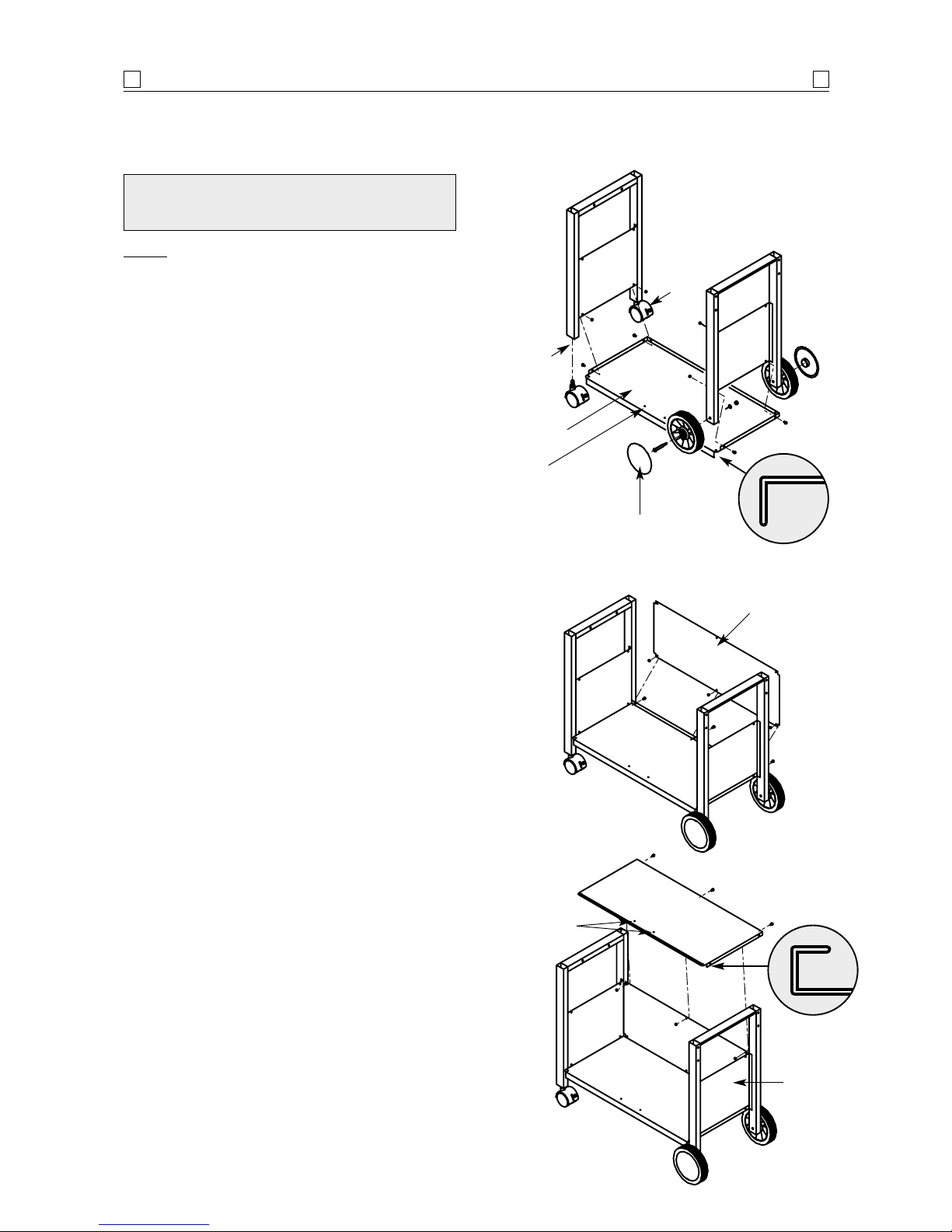
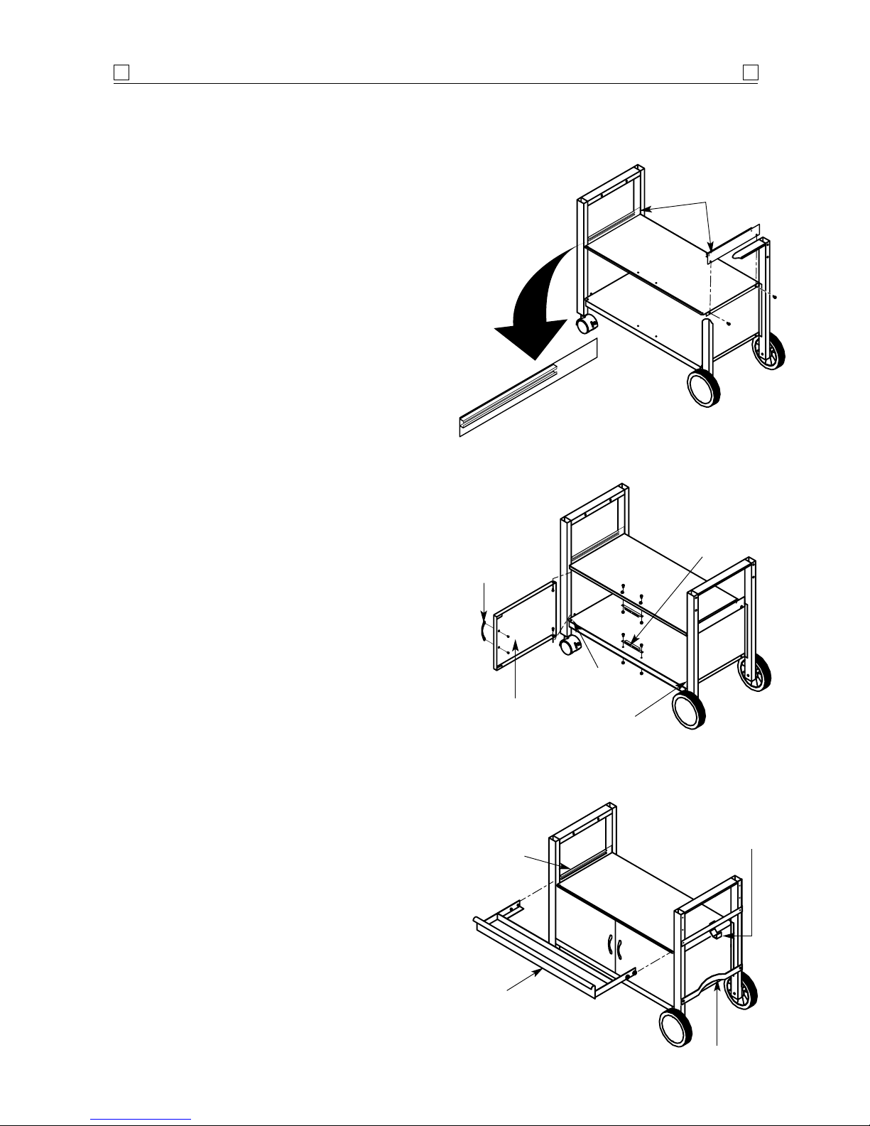
1. Before attaching the trolley legs to bottom shelf
(broader fold), ensure the two (2) holes for magnetic
door stopper are in the front.
See diagram 1.
Install the trolley legs with castor seats to the left
side of bottom shelf. Secure using two (2)
1
/4" x
1
/2" roundhead screws and nuts provided. Install
the remaining trolley leg to the opposite side of
bottom shelf using the same screws and nuts.
Finger tighten only.
Ensure fold of bottom panel is to outer surface.
2. Secure castors to the castor seats of left trolley leg
in a clockwise direction. Tighten securely with
adjustable spanner.
3. Install wheels to right trolley legs by inserting the
wheel bolt through the wheel and axle hole on
the trolley leg as shown below. Tighten securely
using spring washer and
3
/8" nuts provided. Clip
the hubcaps onto the wheels.
4. Install rear panel by using the three (3) 1/4" x 1/2"
phillips-head screws and nuts.
See diagram 2.
Ensure fold of bottom panel is to outer surface.
5. Before installing top panel, ensure the two (2)
holes for door stopper are in the front. Place top
panel onto the rear and side panels.
Ensure fold
is located to the outer surface.
See diagram 3.
Secure firmly using the three (3)
1
/4" x 1/2"
phillips-head screws and nuts provided.
TROLLEY ASSEMBLY This section applies to the
Grand Monaco/Grand Gourmet/Grand Café/Buffet
models. (Refer page 11 for Galley model
)
Hubcap
Castor
seat
Castor
Bottom
shelf
Rear panel
Openings for
magnetic door stopper
Diagram 1.
Diagram 2.
Page 9
Front
door
Threaded
opening
Install second
door this side
Door handle
Magnetic
door stopper
Diagram 5.
TROLLEY ASSEMBLY
9
9
Drawer back panel
Track insert
must be
positioned
to front
Diagram 4.
6. Ignore this step for Buffet model.
Attach drawer track panels to both sides of top
panel refer
diagram 4. Insert the bracket between
the securing screw and fold of top panel. Secure
firmly using the
1
/4" x 1/2" phillips-head screws
and nuts.
7. Install magnetic door stoppers to bottom shelf
and top panel.
See diagram 5. Fix firmly using the
four (4)
1
/4" x 1/2" phillips-head screws and nuts.
8. Remove protective coating on the doors. Install
door handle to front door by using two (2) M4
x6 mm phillips-head screws provided.
See diagram 5.
9. Before installing front doors, visually check and
ensure the threaded integral spacers of the bottom
panels are located in position on the hinge sides
of trolley.
10. Install either front door by inserting
1
/4" x 5/8"
part-threaded bolt through the lower integral
spacer of front door, and then secure to the bottom
panel. Tighten securely. Align the upper spacer
of front door with the top panel and tighten
securely using
1
/4" x 5/8" part-threaded bolt
provided.
11. Repeat the above step to install the other front
door.
12. Attach gas cylinder support to the wheel-side
trolley legs using two (2)
1
/4" x 1/2" roundhead
screws provided.
See diagram 6.
13. Install gas cylinder hook bracket using two (2)
1
/4"
x
1
/2" roundhead screws and wing nut provided.
Gas cylinder
hook bracket
Gas cylinder
support
Drawer
Drawer track
Diagram 6.
Page 10
Side shelf
Side burner
TROLLEY ASSEMBLY
10
10
Diagram 9.
Side shelf
Side burner
Grand Café
Grand Gourmet
Grand Buffet
Grand Monaco
Grand Monaco
(Rinnai Aust)
Diagrams shown without
barbecue body for simplicity.
14. Ignore this step for Buffet model.
Slide the drawer into the tracks on both sides.
15.
Ignore this step for Buffet model.
Install the four (4) 1/4" x 1/2" roundhead screws
into the two (2) threaded screw mounts of both
drawer track panels to restrict the drawer from
being slid beyond the tracks.
See diagram 7.
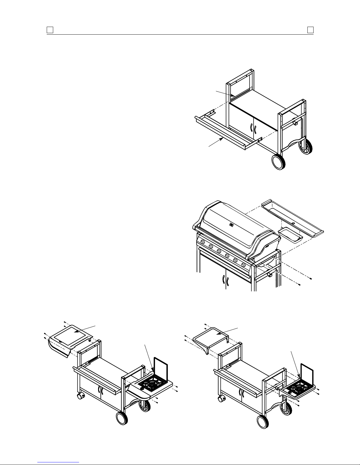
17. You are now ready to install the barbecue into the
trolley. Remove all the loose contents from inside
the barbecue body to lighten the weight. The
installation of the barbecue into the trolley
requires two (2) people to lift it up and into position
so that the edge on the side panels rest firmly on
the trolley leg assembly horizontal braces.
Remove protective coating from hood in the case of the
Grand Monaco.
18. Secure barbecue to trolley with two (2) bolts and
nuts on each side, connecting through the leg
assembly as shown in
diagram 8.
19. Slide the fat/grease draining tray and receptacle
under the barbecue body on the ledges provided,
from the rear of the barbecue.
20. Install the side shelf and side burner to the trolley
by using eight (8)
1
/4" x 3/4" roundhead screws
provided.
See diagram 9.
21. Tighten and secure all screws, bolts and nuts used
throughout this assembly procedure
.
Drawer
Drawer track
Diagram 7.
Diagram 8.
Page 11

TROLLEY ASSEMBLY
11
11
Diagram 10.
Diagram 12.
Bottom shelf
Gas
cylinder
support
Gas
cylinder
hook
Right-angled
brace
Wheel
Hubcap
Castor
legs
Castor
Short
axle legs
Do not tighten bolts until all fittings are in position.
1. Place the legs with axle holes together on a clean
surface on their narrow sides. Position a rightangled brace between the legs as shown in diagram
10 and connect each leg to the brace using four (4)
1
/4" x 1/2" screws provided.
2. Repeat steps above using the remaining two leg
pieces.
3. Position the solid base tray in alignment with the
openings provided in each leg as shown in
diagram
10. Secure the base tray using eight (8) 1/4" x
21/2" bolts and nuts provided. Finger tighten
only.
4. Attach the gas cylinder hook bracket to the rear
of wheel-side trolley leg with
1
/4" x 21/2" bolt
and nut. Secure the front end of the bracket
along with the support brace to the same mounting
hole. Secure the other end of the support brace to
the front castor leg.
5. Attach the gas cylinder support as shown with
two (2)
1
/4" x 3/4" roundhead screws.
6. Carefully place the partly assembled trolley to a
laying down position and screw the castors into
the legs with the pre-fitted castor seats in them.
Fasten firmly using a shifter.
7. Secure wheels to other legs using the long axle
bolts and nuts provided. Be sure to insert the
washer onto the axle bolt so that it is positioned
between the trolley leg and securing nut. Clip
hubcaps into centre of wheels.
Refer diagram 10.
8. You are now ready to install the barbecue into the
trolley. Remove all the loose contents from inside
the barbecue body to lighten the weight. The
installation of the barbecue into the trolley
requires two (2) people to lift it up and into
position so that the edge on the side panels rest
firmly on the trolley leg assembly horizontal
braces.
9. Secure barbecue to trolley with two (2) 1/4" x 1"
bolts and nuts on each side, connecting through
the leg assembly as shown in diagram 11.
10. Slide the fat/grease draining tray and receptacle
under the barbecue body on the ledges provided,
from the rear of the barbecue.
11. Install the side shelf and side burner to the trolley
by using eight (8)
1
/4" x 3/4" roundhead screws
provided. See diagram 12.
12. Tighten and secure all screws, bolts and nuts
used throughout this assembly procedure.
TROLLEY ASSEMBLY
(Galley model trolley assembly only)
Support
brace
Diagram 11.
Page 12

CABINET ASSEMBLY
12
12
Side panel
Top panel
Openings for
magnetic door
stopper
Diagram 3.
Bottom
shelf
Rear panel
Openings for
magnetic door stopper
Diagram 1.
Diagram 2.
CONTENTS OF KIT
2 Legsets with storage cabinet end panels.
1 Back panel (storage cabinet) 900 x 245 mm.
1 Top panel (storage cabinet) 900 x 415 mm.
1 Bottom panel (storage cabinet) 900 x 415 mm.
2 Door assemblies.
2 Magnetic door stoppers.
2 Door handles.
1 Accessory pack.
2 Trim plates.
1. Before attaching the cabinet legs to bottom shelf
(broader fold), ensure the two (2) holes for magnetic
door stopper are in the front.
See diagram 1.
Secure using two (2)
1
/4" x 1/2" roundhead screws
and nuts provided. Install the remaining cabinet
leg to the opposite side of bottom shelf using the
same screws and nuts. Finger tighten only.
2. Install rear panel by using the three (3)
1
/4" x 1/2"
phillips-head screws and nuts.
See diagram 2.
Ensure fold of bottom panel is to outer surface.
3. Before installing top panel, ensure the two (2)
holes for magnetic door stopper are in the front.
Place top panel onto the rear and side panels.
Ensure fold is located to the outer surface.
See
diagram 3
. Secure firmly using the seven (7) 1/4" x
1
/2" phillips-head screws and nuts provided.
STORAGE CABINET ASSEMBLY
(Built-in model)
Page 13

Threaded
opening
Door handle
Diagram 5.
CABINET ASSEMBLY
13
13
Magnetic
door stopper
Diagram 4.
4. Install magnetic door stoppers to bottom shelf
and top panel.
See diagram 4. Fix firmly using the
four (4)
1
/4" x 1/2" phillips-head screws and nuts.
5. Remove protective coating on the doors. Install
door handle to front door by using two (2) M4
x6 mm phillips-head screws provided.
See diagram 5.
6. Before installing front doors, visually check and
ensure the threaded integral spacers of panels are
located in position on the hinge sides of cabinet
top and bottom panels.
7. Install either front door by inserting
1
/4" x 5/8"
part-threaded bolt through the lower integral
spacer of front door, and then secure to the bottom
panel. Tighten securely. Align the upper spacer
of front door with the top panel and tighten
securely using
1
/4" x 5/8" part-threaded bolt
provided.
8. Repeat the above step to install the other front
door.
9. Place the trim-left and trim-right over the cabinet
legs. Align the hole in the trim plate with the
tapped hole on the cabinet. Tighten securely
using
1
/4" x 1/2" phillips-head screw.
See diagram 6.
Diagram 6.
Trim-left
Trim-right
Page 14

CABINET ASSEMBLY
14
14
NOTE: Study the assembly diagram and check the
parts listed.
Do not tighten bolts until all fittings are in position.
1. Before attaching the bowl support bracket to
frame A ensure that the two holes for the trim
plate are facing outward.
See diagram, right.
Secure the bowl support bracket to Frame A
using two (2)
1
/4" x 1/2" screws provided. Attach
Frame B to the other end of the bowl support
bracket using two (2)
1
/4" x 1/2" screws.
2. Install bracket to the above piece using two (2)
1
/4" x 1/2" screws.
3. Mount trim plate over the part completed in step
2 using two (2)
1
/4" x 1/2" screws on the front
panel as shown in diagram, right.
4. Using three (3)
1
/4" x 3/4" screws and 1/4" nuts to
secure the top section to the bowl support bracket.
5. Tighten and secure all screws, bolts and nuts
used throughout this assembly procedure.
NOTE: The additional two sets of 1/4" x 3/4" screws
and 1/4" nuts are for securing the barbecue body to the
Built in support brackets.
BUILT-IN SUPPORT BRACKET
Bracket
Trim plate
(left)
Frame B
Trim plate
(right)
Top
Front
Bowl support
bracket
Bowl support
bracket
Bracket Frame A
Part description
2 Bowl support bracket
2 Frame A with additional 2 holes
2 Frame B
2 Bracket
1 Trim plate left
1 Trim plate right
Accessories
161/4" x 1/2" screws
10
1
/4" x 3/4" screws
10
1
/4" nuts
ONLY AVAILABLE FOR USE WITH
NATURAL GAS INSTALLATIONS
!
Page 15

ASSEMBLY
15
15
TEST FOR LEAKS WITH A
SOAP SOLUTION.
NEVER WITH AN OPEN FLAME.
!
IMPORTANT:
Before connecting and disconnecting
barbecue to gas source, make sure burner controls are
in ‘OFF’ position.
1. Familiarise yourself with the general information
and safety guidelines located at the front of this
manual.
2. Check to see that gas cylinder is filled.
3. Check that end of each burner tube is properly
located over each valve orifice.
4. Set burner controls to
‘OFF’ position.
CONNECTING AND DISCONNECTING
TO GAS SOURCE
1. Hang filled gas cylinder on the cylinder hook.
2. Attach quick connect device of regulator and hose
assembly to cylinder valve outlet.
3. Open the gas cylinder
valve fully to allow gas
to flow.
4. Leak test all connec-
tions thoroughly with a
soapy water solution
prior to lighting the
barbecue.
(See Safety, page 4).
5. If a leak is found, turn gas cylinder valve off and
do not use barbecue until repairs or replacement
can be made by a local LP gas dealer.
CAUTION:
When the appliance is not in use, the gas
must be turned off at the gas cylinder.
DISCONNECTING FROM GAS SOURCE:
a) Turn the burner control ‘OFF’.
b) Turn the gas cylinder valve off fully.
c) Detach the regulator assembly from gas
cylinder valve by turning the quick coupling nut.
PROPANE INSTALLATION
1. A 300 mm hose is factory
fitted to the dual outlet
adaptor of the side
burner control valve.
Attach the other end to
the main barbecue
manifold inlet and
tighten with a shifter.
Take care not to overtighten.
2. Attach regulator hose
to outlet of dual outlet
adaptor. Tighten with
shifter taking, care not
to overtighten.
3. Leak test all connections thoroughly with a soapy
water solution prior to lighting the barbecue.
(Refer page 19 for lighting instructions for side burner).
INSTALLATION OF SIDE BURNER
GAS PIPING CONNECTION
1. Locate loose ignition wire under control panel on
right side of barbecue.
2. Pass wire under barbecue side panel and behind
trolley leg.
3. Connect to ignition wire hanging from side burner.
SIDE BURNER
IGNITION WIRE CONNECTION (Monaco)
Page 16

ASSEMBLY
16
16
NEVER USE VOLCANIC ROCK,
HEAT BEADS OR OTHER MATERIAL
ON FLAMETAMER.
!
CHECK PERFORMANCE OF
BURNERS PRIOR TO INSTALLING
BARBECUE PLATE COMPONENTRY.
DO NOT SMOKE WHEN ATTEMPTING
TO IGNITE BARBECUE.
!
CAUTION: WHEN BARBECUE IS NOT
IN USE, DISCONNECT AND PROTECT
ALL GAS FITTINGS.
!
ALWAYS USE PROTECTIVE
GLOVES WHEN HANDLING HOT
COMPONENTS.
!
CONTENTS OF FAT/GREASE
DRAINING TRAY AND FAT/GREASE
RECEPTACLE MAY BE VERY HOT
DURING COOKING.
ALLOW TO COOL COMPLETELY
BEFORE DISPOSING OF THE
CONTENTS.
LINING THE FAT/GREASE
RECEPTACLE WITH ALUMINIUM FOIL
ENABLES EASIER CLEANING.
REMEMBER:
REPLACE FAT/GREASE
RECEPTACLE FOIL REGULARLY.
AFTER CONTINUOUS USE, FAT AND/
OR COOKING JUICES MAY BUILD UP.
TO AVOID ANY FLARE-UPS, IT IS
RECOMMENDED THAT THE
FAT/GREASE TRAY AND RECEPTACLE
BE EMPTIED REGULARLY.
!
1. With burner controls in ‘OFF’ position, turn on
cylinder or connect to gas supply.
2. Upon first assembly the gas lines and burners
will be full of air. In order for the burners to light
properly the lines must fill with gas. It may
require several attempts at lighting the burners
before you are successful.
3. Push the electronic multi-spark button located in
the centre of the control panel and check for
sparking at the stainless steel gas collector, located
between burners.
4. If a spark is not evident at the gas collector, check
that the ignition lead is firmly attached to the
ignition pack and spark plug.
5. With sparking established at collector box, turn
the burner control to
‘HIGH’ while simultaneously
pressing the igniter button.
6. Push and turn the centre and left burner controls
in an anti-clockwise direction to the
‘HIGH’
position. Cross lighting channels inside the
barbecue body enables the flame to transfer across
to the centre and left burners to ignite them.
7. If any burners fail to light after 10 seconds, turn
off supply, wait 5 minutes and retry.
Wait until burners cool and inspect for obstructions to
gas flow.
See also Safety instructions (page 4), Lighting
and Operating instructions (page 18)
.
BURNER OPERATION AND
IGNITION SYSTEM CHECK
This barbecue is also certified for use on natural
gas. It must be converted by an authorised person.
Contact Rinnai or the supplier for advice in relation
to using your barbecue on natural gas.
If your barbecue is supplied direct from the factory
in a natural gas specification, then it must be installed
by an authorised person.
NATURAL GAS INSTALLATION
Burner control
Burner tube
Gas valve
assembly
Gas collector box
Foot
Cotter pin
Spark electrode
Burner Burner port
Page 17

The temperature gauge is
used as a guide to cooking temperatures when cooking with the
hood closed. There is a hole in the
centre, front of the hood to allow
installation of the temperature
gauge.
Install as shown in the diagram.
THE TEMPERATURE GAUGE
Diagram 13.
Swing-away
warming rack
Solid grillplate
Cooking pan
Ceramic
flametamer
(Grand Monaco/
Grand Gourmet)
Stainless
steel rack
(Grand Monaco/
Grand Gourmet)
Cast iron
flametamer
(Galley/Buffet/
Grand Café)
Fixed warming rack
(Grand Monaco/
Grand Gourmet)
Remove rubber antiscuffing sleeves from
both sides of barbecue
side panels
Slotted grillplate
ASSEMBLY
17
17
Check and ensure each burner is properly located over
orifice prior to installing the plates.
IMPORTANT: Before first use, wash the grillplates
and warming rack with warm, soapy water. Rinse
and dry thoroughly. Season with cooking oil regularly.
After cooking is completed, turn barbecue to high
setting for five minutes to burn-off excess grease or
food residue.
1. Place one (1) stainless steel rack on the lower
ledge above burners and in the centre of the
barbecue body. Lay four (4) pieces of ceramic
flametamer provided over rack evenly, with
small openings upward.
See diagram 13.
2. Place cast iron slotted grillplate in the barbecue
body on the ledge above the ceramic flametamer.
3. Position cooking pan to the right side and the
solid plate to the left.
4. The barbecue hood has a ‘U’ shaped notch on
each side of hood interior. Fix arms of the swingaway warming rack into these notches.
5. The fixed warming rack is located via two (2)
slots per side at the rear of the barbecue body
side panels.
COOKING COMPONENT INSTALLATION
(Grand Monaco/Grand Gourmet)
IMPORTANT: Before first use, wash the grillplates
and warming rack with warm, soapy water. Rinse
and dry thoroughly. Season with cooking oil regularly.
After cooking is completed, turn barbecue to ‘HIGH’
setting for five minutes to burn-off excess grease or
food residue.
1. The cast iron flametamer is designed
to reduce flaring. Fit onto the
ledges at the front and rear of the
barbecue body in the centre position with the flared slots to the
top, shown here.
2. Place cast iron slotted grillplate in the barbecue
body on the ledge directly above the flametamer.
3. Position cooking pan to the right side and solid
grillplate to the left.
4. The barbecue hood has a ‘U’ shaped notch on
each side of hood interior. Fix arms of the swingaway warming rack into these notches.
COOKING COMPONENT INSTALLATION
(Grand Café/Buffet/Galley)
Page 18

OPERATION
18
18
Burn-off:
Before cooking on your BBQ for the first time, burn-off
any residual oils or foreign matter by igniting the burners.
ENSURE THE LID IS REMOVED OR THE HOOD OPEN,
and operate at
‘HIGH’ setting for approximately 10 minutes.
Wipe with cloth to remove all residue. Allow to cool before
washing grill/plate/pan thoroughly with soap suds and
scrubbing brush. Wipe clean with cloth. Your grill/
plate/pan is ready to use.
Preheating:
It is necessary to preheat the BBQ for a short time
before cooking certain foods, depending on the type of
food and the cooking temperature. Food that requires a
high cooking temperature needs only a period of 2 - 3
minutes preheating.
OPERATING PROCEDURE
1. Become familiar with safety guidelines at front of
this manual.
2. Check to see that gas cylinder is filled.
3. Check that end of each burner tube is properly
located over each valve orifice.
4. Ensure all gas connections are securely tightened.
5. Always open hood before lighting.
6. Set burner controls to
‘OFF’ and connect the gas
supply.
LIGHTING PROCEDURE
The Rinnai Outdoor Kitchen 6 Burner is fitted with
electronic multi-spark ignition to each burner.
AFTER PERFORMING BURNER OPERATION AND
IGNITION SYSTEM CHECK
(page 16), THE BARBECUE
IS READY TO IGNITE.
Push and turn the required burner to
‘HIGH’;
while simultaneously pressing the electronic ignition
button located in the centre of the control panel.
The burner should light within 10 seconds. If the
burner does not light, turn to
‘OFF’ and wait 5 minutes.
Repeat lighting procedure for other burners. If
ignition cannot be achieved, re-perform ignition system
check procedure
(page 16).
NOTE: If for some reason, igniters fail to produce a
spark at the electrode tip, barbecue can be lit carefully
with a match.
To light burners with a match, insert lighted
fireplace-type match or long-necked butane lighter
through lighting hole located on left side of barbecue
body. Press in left burner control and rotate left to
‘HIGH’ setting to release gas. Burner should light
immediately.
If more than one burner is needed, press in and
rotate next burner control to light in sequence from
the lit burner.
Turn burners not needed to
‘OFF’ and adjust
other burner controls to desired cooking temperature.
IGNITION SYSTEM
‘HIGH’ setting - Use this setting only for fast warm
up, for searing steaks and chops, and for burning food
residue from the grillplates after the cookout is over.
Rarely, if ever, do you use the ‘
HIGH’ setting for extended
cooking.
‘MEDIUM’ setting (mid-way between ‘HIGH’ and
‘LOW’).
Use this setting for most grilling, and for cooking
hamburgers and vegetables.
‘LOW’ setting - Use this setting when cooking very
lean cuts such as fish.
These temperatures vary with outside temperature
and the amount of wind.
Flare-ups: The fats and juices that drip from the meat
cause flare-ups. Since flare-ups impart the distinctive
taste and colour for food cooked over an open flame, they
should be expected and encouraged within reason.
Nevertheless, uncontrolled flaring can result in a
ruined meal.
COOKING TEMPERATURES
HOOD MUST BE OPEN BEFORE
LIGHTING.
!
Before first use and at the beginning of each barbecue
season:
1. Please read
Safety, Lighting and Operating
instructions
carefully.
2. Check gas valve orifices, burner tubes and burner
ports for any obstructions.
3. Check and ensure the gas cylinder is full.
4. Ensure all connections are securely tightened. Check
for gas leaks.
See page 4.
NOW YOUR BARBECUE IS READY TO USE
THE HOOD MUST BE IN THE OPEN
POSITION FOR LIGHTING
DO NOT SMOKE AT ALL TIMES WHEN
ATTEMPTING TO IGNITE BARBECUE.
CAUTION:
DO NOT MOVE TROLLEY
WHILE BARBECUE IS IN OPERATION
!
Page 19

OPERATION
19
19
Cooking with the hood in the closed position
helps to cook food more quickly than in conventional
barbecues with a simple lid. The hood
(when closed)
helps to retain the heat more evenly and conserves
energy. For the best cooking results, always use the
burners on low or use the indirect cooking method
(explained below) when the hood is down. High direct
heat on the cooking plates when the hood is down
may result in burnt food, or damage to painted surfaces.
NEVER USE ALL BURNERS ON HIGH AT THE
SAME TIME WHEN COOKING WITH THE HOOD
DOWN.
The following method is referred to as
‘INDIRECT
COOKING’
. Poultry and large cuts of meat cook slowly
to perfection on the barbecue by indirect heat.
Use burners 1+2 and 5+6. The heat from the
selected burners circulates gently throughout the
barbecue, cooking the meat or poultry without any
direct flame touching it. This method greatly reduces
flare-ups when cooking extra fatty cuts, because there
is no direct flame to ignite the fats and juices that
drip during cooking.
Plate positions (without
cast iron cooking pan)
Remove solid hotplate and cooking pan. Position
slotted grillplates and flametamers together in centre
of barbecue over the centre burners. Remember, only
use outside burners for indirect cooking,
(as
described above)
.
Plate positions (with cast iron cooking pan)
Position the cooking pan over the two (2) centre
burners, position the slotted grillplate on either side of
the pan. Ignite the 2 outer left and right burners on
both sides of the barbecue,
(the 2 burners under the cooking
pan should remain ‘OFF’)
.
Burner control
The 6 burner design gives maximum control for oven
cooking. With the hood open, ignite the two (2) outer
left and right burners. Once ignition is established,
close the hood. Leave the burners
(4 maximum) on
‘HIGH’ for 5 - 7 minutes or until the temperature
reaches a suitable level for cooking. Modulate the
required temperature by turning the outermost left
and right burners progressively to
‘LOW’.
COOKING WITH THE HOOD DOWN
Lid must be open before lighting. For easy ignition,
push the burner control in fully. Slowly rotate the
control anti-clockwise through 90 degrees
(approx. 3 -
4 seconds)
until a click is
heard, this will trigger the
piezo, producing a spark at
the burner.
The 3 - 4 second duration
should provide enough gas to
light the burner. If the burner
does not light, immediately
return the burner control to
the
‘OFF’ position and repeat
the process.
Turn burner control to
‘HIGH’ following lighting
procedure until flame appears
on the burner. If for some
reason the igniter fails to
produce a spark at the electrode tip, the burner can be
lit using a standard match.
LIGHTING THE SIDE BURNER
(ROTARY PIEZO IGNITION)
(Grand Gourmet/Grand Café/Buffet/Galley
models only)
THE SIDE BURNER IS DESIGNED FOR
USE WITH A WOK OR COOKING POTS
UP TO 300 mm DIAMETER.
USE OF VERY LARGE POTS MAY
RESULT IN DISCOLOURATION OF THE
SURFACE FINISH.
!
The Grand Monaco side burner is ignited using
the same method as the main barbecue burners.
Push and turn the burner control to the
‘HIGH’
position while simultaneously pressing the electronic
ignition button located in the centre of the control
panel.
LIGHTING PROCEDURE
(Push button continuous spark)
Grand Monaco
Page 20

ROTISSERIE COOKING
20
20
The Grand Monaco model comes with a unique
240 Volt driven rotisserie motor. Grand Gourmet and
Grand Café come with a battery powered rotisserie
motor. In using each type of rotisserie there are some
important safety points to consider.
Always attach rotisserie to barbecue first before
commencing rotation of the spit via the motor.
Always plug 240 Volt model cord into the supply
socket. To disconnect, turn rotisserie
‘OFF’, then remove
plug from supply socket.
Most barbecue surfaces and accessories are hot
during and after cooking, so use reasonable care around
barbecue, wear protective mitts, and use rotisserie with
handle attached.
To protect against electrical shock, do not immerse
electrical cord, plug or motor in water or expose to
rain. Avoid contact between electrical elements and
burners, hot barbecue surfaces and grease.
Do not operate rotisserie with a damaged cord or
plug, or if the rotisserie malfunctions or has been damaged in any manner. Return rotisserie to the place of
purchase or authorised service facility for examination,
repair, or replacement.
Unplug rotisserie from electrical supply when
not in use, and before cleaning. Allow to cool before
handling.
This rotisserie is for use outdoors only, and on a
barbecue as described in the following instructions.
Do not leave the rotisserie on the bracket of the
barbecue during times when the barbecue is not in
use.
Do not use rotisserie on the barbecue at times
when it is exposed to inclement weather conditions.
If the supply cord of this appliance is damaged, it
must be replaced by the manufacturer or our authorised service agent.
Close supervision is necessary when rotisserie is
in use nearby children.
Do not allow children to operate barbecue or
rotisserie, and do not let children play nearby.
Unplug rotisserie from electrical supply when
not in use, and before cleaning. Allow to cool before
handling.
The use of accessory attachments is not recommended by the manufacturer and may cause injuries
or damage. Do not use rotisserie for other than intended
use, with barbecue.
IMPORTANT SAFETY POINTS
The fats and juices that drip from the meat may
cause flare-ups. Since flare-ups impart the distinctive
taste and colour for food cooked over an open flame,
they should be expected and encouraged within reason.
Nevertheless, uncontrolled flaring can result in a
ruined meal.
FLARE-UPS
To load the spit rods, begin with handle in place
on slot located in barbecue side panel. Slide one of the
holding forks
(with prongs facing away from the handle)
onto the spit rod. Push the spit rod through the centre
of the food to be basted, and then slide the second
holding fork,
(prongs toward the food) onto the spit rod.
It is very important to centre and balance the
food to be cooked on the spit rod, then push the meat
holding forks firmly together. Tighten the wing nuts
with pliers. It may also be necessary to wrap the food
with butcher string
(never use plastic or nylon string) to
secure any loose portions. Once the food is secure
insert the spit rod into the rotisserie motor.
It may be necessary to remove the barbecue cooking
plates depending upon the size of the meat. Place a
basting pan below the food to collect the falling juices
and drippings. It is normal for the spit rods to flex a
little when larger cuts of meats are being cooked.
Note: 240 V rotisserie – 5 kg maximum.
Battery rotisserie – 3 kg maximum.
LOADING THE SPIT RODS
When rotisserie cooking, place a drip pan of some
sort under the food to be cooked. This will capture the
drippings and keep barbecue clean of excess grease
which could cause a fire. Water may be added to drip
pan to retain moisture. Use caution when moving a
drip pan containing hot oils, or grease.
Never line the bottom of your barbecue body
with aluminum foil, sand or any grease absorbent
substance.
Should a grease fire occur, turn the burners and
gas off immediately and leave hood CLOSED until fire
is extinguished.
This rotisserie is for use outdoors only, and on a
barbecue as described in the following instructions.
Fit rotisserie bracket to opposite side of barbecue
where a side burner is fitted. The projection of the
rotisserie handle will preclude use of side burner.
Page 21

BEWARE OF SPIDERS.
BURNER TUBES SHOULD BE
INSPECTED AND CLEANED
PERIODICALLY.
SPIDERS AND SMALL INSECTS CAN
OCCASIONALLY SPIN WEBS OR MAKE
NESTS IN THE BURNER TUBES. THESE
WEBS CAN LEAD TO A GAS FLOW
OBSTRUCTION WHICH COULD
RESULT IN A FIRE IN AND AROUND
THE BURNER TUBES.
THIS TYPE OF FIRE IS KNOWN AS
‘FLASH-BACK’ AND CAN CAUSE
SERIOUS DAMAGE TO YOUR
BARBECUE AND CREATE AN UNSAFE
OPERATING CONDITION FOR THE
USER.
ALTHOUGH AN OBSTRUCTED BURNER
TUBE IS NOT THE ONLY CAUSE OF
‘FLASH-BACK’ IT IS THE MOST
COMMON CAUSE AND FREQUENT
INSPECTION AND CLEANING OF THE
BURNER TUBES IS NECESSARY.
!
Occasionally observe burner flame for correct
operation
. See diagram below.
VISUALLY CHECKING BURNER FLAMES
1. Turn off gas at source, turn burner control to
‘OFF’.
2. Wait five minutes before trying again.
3. Check gas supply/connections.
4. Repeat lighting procedure and, if barbecue still
fails to operate properly, TURN OFF GAS AT
SOURCE, TURN BURNER CONTROLS TO
‘OFF’,
wait for barbecue to cool and check the following:
a) Misalignment of burner tube(s) and over orifice(s).
CORRECTION: Reposition burner tube to properly
sit over orifice.
b) Obstruction in gas line
CORRECTION: Remove hose from barbecue.
DO NOT SMOKE! Open gas supply for one second to
blow any obstruction from fuel hose. Close off gas
supply at source and reconnect hose to barbecue.
c) Blocked orifice
CORRECTION: Remove grillplates, flametamers,
fat/grease draining tray and receptacle. Remove
burners from bottom of barbecue body by pulling
cotter pin from beneath burner ‘foot’ using a
screwdriver or needle nose pliers.
(See burner
diagram on page 15).
Carefully lift each burner up
and away from gas valve orifice. Remove the orifice
section of gas valve from each gas valve and gently
clear any obstruction with a fine wire. Re-install
each orifice section, re-install burners over orifices
and place each burner ‘foot’ into mounting bracket
at bottom of barbecue body. Replace cotter pins.
Replace cooking components, fat/grease draining
tray and receptacle.
d) Misalignment of igniter on burner
CORRECTION: Check for proper position of elec-
trode tip. The tip of the electrode should be
pointing toward the tip of the collector box. The
gap between the spark electrode and the tip of the
gas collector box should be 5 mm. Adjust if
necessary by carefully pressing the gas collector
closer to the spark electrode.
If re-ignition is necessary while the barbecue is
still hot, you must wait for a minimum of five minutes
before commencing to re-ignite.
(This allows accumulated
gas to clear).
If all check/corrections have been made and
barbecue still fails to operate properly, consult your
barbecue dealer or gas appliance service person.
IF BARBECUE FAILS TO OPERATE PROPERLY
CAUTION: IF BURNERS GO OUT
DURING OPERATION, CLOSE GAS
SUPPLY AT SOURCE, AND TURN ALL
GAS VALVES OFF.
OPEN HOOD AND WAIT 5 MINUTES
BEFORE RE-ATTEMPTING TO LIGHT
(THIS ALLOWS ACCUMULATED GAS
FUMES TO CLEAR).
CAUTION:
SHOULD A GREASE FIRE
OCCUR, CLOSE GAS SUPPLY AT
SOURCE, TURN OFF ALL BURNERS
AND REMOVE FOOD UNTIL FIRE IS
OUT.
KEEP THE VENTILATION OPENINGS
OF THE CYLINDER ENCLOSURE FREE
AND CLEAR FROM DEBRIS.
!
OPERATION
21
21
Page 22

MAINTENANCE
22
22
To reduce the chance of flash-back, the procedure
below should be followed at least once a month in late
summer or early autumn when spiders are most
active, or when your barbecue has not been used for
an extended period of time.
1. Remove grillplates, flametamers, fat/grease
draining tray and receptacle from barbecue.
2. Remove burners from bottom of barbecue body
by pulling cotter pin from beneath burner ‘foot’
using a screwdriver or needle nose pliers.
3. Carefully lift each burner up and away from gas
valve orifice.
We suggest several different ways of cleaning the
burner tubes. Use the procedure most convenient for
you:
1. Bend a stiff wire
(a light weight coat hanger works
well)
into a small hook. Run the hook through
each burner tube and into the burner several
times.
CLEANING THE BURNER TUBES AND
BURNER PORTS (TO PREVENT FLASH-BACK)
OR Using a narrow bottle brush with a flexible handle
(do not use a brass wire brush), run the brush
through each burner tube and into the burner
several times.
OR Use an air hose to force air through the burner
tube and out through the burner ports. Observe
each port and make sure air comes out every
hole. Wear eye protection.
Regardless of which burner cleaning procedure
you use, we recommend that you complete the following
steps to help prolong burner life.
1. Wire brush entire outer surface of burner to
remove food residue and dirt.
2. Clean any blocked ports with a stiff wire such as
an open paper clip.
3. Inspect the burner for damage
(cracks or holes)
and if such damage is found, order and install a
new burner. After installation, check to ensure
that gas valve orifices are correctly placed inside
ends of burner tubes. Also check position of
spark electrode.
If fire occurs in and around the burner tubes,
immediately turn off gas at its source and turn the
burner control(s) to
‘OFF’. Wait until the barbecue has
cooled, then clean the burner tubes and burner ports
as described below.
FLASH-BACK
As with all appliances, proper care and maintenance will keep them in top operating condition and
prolong their life. Your new gas barbecue is no exception. By following these cleaning procedures on a
timely basis, your barbecue will be kept clean and
working properly with minimum effort.
CARE AND MAINTENANCE
After cooking, turn burner controls to ‘OFF’ and
let barbecue cool before attempting to clean your
grillplates. Take care not to chip the porcelain coating.
Before first use and periodically it is suggested
that you wash the grillplates in a mild soap and warm
water solution. You can use a wash cloth, a vegetable
brush, or steel wool to clean your cooking plates if you
desire.
CLEANING THE GRILLPLATES
Rotate the chrome cap
anti-clockwise to remove it
completely. The ignition
pack is powered by a ‘AA’
battery.
The battery can be
easily removed using your
fingers.
IGNITION SYSTEM BATTERY REPLACEMENT
Washing the flametamer after every use is not
necessary but periodically it is suggested you wash the
flametamer in a mild soap and warm water solution.
Use a wire brush to remove stubborn burnt on cooking
residue. Dry the flametamer thoroughly before you
re-install it in the barbecue body.
CLEANING THE FLAMETAMER
The fat/grease draining tray should be emptied
and wiped down periodically and washed in a mild
detergent and warm water solution.
CLEANING THE FAT/GREASE DRAINING TRAY
& FAT/GREASE RECEPTACLE
IN COASTAL AREAS, MORE REGULAR
CLEANING AND THE USE OF A COVER
IS RECOMMENDED. SALTY AIR MAY
AFFECT THE TROLLEY. PLEASE WASH
DOWN WITH FRESH WATER.
!
Page 23

RINNAI GUARANTEE
23
23
✁
YOUR DETAILS
Mr Mrs Ms Other:
Surname: Given name:
Address:
Suburb/Town: State: P/code:
Telephone ( ) A/H, Bus.
YOUR BARBECUE DETAILS
Date of purchase:
Place of purchase:
Serial No. located on front/side panel:
ADDITIONAL DETAILS
(Optional questions to assist our continuous improvement program)
Before this purchase, were you aware of Rinnai Aust? Yes No
If yes, were you aware that Rinnai produced
an extensive barbecue range? Yes No
What was your final choice based on?
Colour Price Features Style Other:
Were you recommended to this product by
Retailer Friend Advertising Past Experience Other:
Did you previously own a barbecue? Yes No
If yes, what kind? Portable Kettle Inbuilt
Volcanic Rock/Charcoal Same Other:
If you changed, why?
Your age 20-25 26-30 31-35 36-40 41-45 46-50 50+
Burning-off the barbecue after cooking will keep it
ready for instant use, however, at least once a year you
should give the entire barbecue a thorough cleaning to
keep it in top operating condition.
Interior:
1. Turn the burner controls to ‘OFF’ position.
2. Turn the cylinder valve off fully.
3. Detach the regulator assembly from cylinder valve
by turning the quick coupling nut.
4. Remove and clean the cooking plates, flametamers
and burners. Lightly oil after cleaning.
5. Cover the gas valve orifices with a piece of aluminium
foil.
6. Brush the inside and bottom of the barbecue with a
stiff wire brush, and wash down with a mild soap
and warm water solution. Rinse thoroughly and let
dry.
7. Remove aluminium foil from orifices and check
orifices for any obstruction.
8. Check spark electrode, adjusting as instructed.
Electrode tip pointing toward the bottom of gas
collector and approximately 5 mm
(1/5") from the
bottom of collector box.
9. Replace burners and adjust spark electrode collector
box.
10. Replace flametamers, grillplates and warming rack.
11. Reconnect to gas and check for leaks then observe
burner flame for correct operation.
As with all appliances, proper care and maintenance
will keep them in a top operating condition and prolong
their life. Your barbecue is no exception. By following
these cleaning procedures on a timely basis, your barbecue
will be kept clean and working properly with minimum
effort.
Exterior:
Your gas barbecue is made of heavy steel, it should
provide you with years of trouble-free service. Touch-up
any scratches in the paint which may occur with use.
These scratches may expose bare metal and leave the unit
susceptible to material breakdown. A touch-up paint
designed for use with high temperatures is available in
most hardware stores and from your barbecue dealer.
Follow these steps for best results when applying touch-up
paint:
1. Shut off gas supply at source and disconnect gas hose
from gas valve manifold. Protect gas hose fitting.
2. Remove loose paint by lightly sanding surface(s)
with a medium grit emery cloth or a fine grit sand-
paper.
3. Remove any dirt or grease by washing the surface(s)
with a mild soap and warm water solution.
4. Rinse with clean water and allow surface to dry
thoroughly or wipe the area with vinegar.
5. Apply touch-up paint properly by following
instructions on can.
6. Allow paint to dry completely, and apply a second
coat if necessary.
IMPORTANT: Allow paint to dry at least 24 hours before
using your gas barbecue.
CLEANING OF BARBECUE HOUSING
Rinnai recommends that you minimise the units’
exposure to the elements. High moisture content in the
air
(rain, mist, salt spray etc.) can affect metal components
of this product and lead to material breakdown. If left in
an area subjected to high moisture content, we strongly
recommend that you observe the cleaning procedure on a
regular basis and cover the unit whilst not in use
(Covers
are available as an optional extra on some models)
. Material
breakdown from high moisture conditions may be considered as normal wear and tear unless full regular
cleaning has taken place.
STORAGE
Page 24
CONTACT POINTS
24
24
All specifications are subject to change without notification.
Printed 7/2001
REPLY PAID 50
RINNAI AUSTRALIA PTY LTD
ABN 74 005 138 769
MARKETING DEPARTMENT
PO BOX 460
MORDIALLOC VICTORIA 3195
No postage stamp required
if posted in Australia
As the purchaser of a high quality Rinnai barbecue, we
provide you with the following guarantee.
FREE Labour* 3 years
FREE Parts* 3 years
*except ignition, flametamers, accessories (1 year)
New Zealand 1 year free parts
and labour all models
The benefits conferred by this guarantee are in addition
to all other rights and remedies in respect of the product
which you have under the Trade Practices Act
(Consumer
Guarantees Act NZ)
and other state and territory laws.
Guarantee does not cover cleaning and normal wear
and tear; calls of this nature may be chargeable. Service
calls to a barbecue which is operating normally may be
chargeable, even when the barbecue is under guarantee.
Please complete and mail this card. This will assist
Rinnai in providing the best possible service.
Note: Where the appliance is installed within 500 m
of breaking surf, non-stainless steel components may be
subjected to material breakdown, and extra attention to
maintenance must be observed. These conditions may
affect a warranty.
GUARANTEE
Rinnai Australia has a service network in most states.
Our service network personnel are fully trained and
equipped to give the best service on your Rinnai appliance.
If your barbecue needs service please ring one of the contact
numbers on this page.
RINNAI AUSTRALIA PTY. LTD. ABN 74 005 138 769
Rinnai
Help Line: 1 300 366 388, 8.00am - 5.30pm EST Mon -Fri
(Cost of a local call. Higher from mobile or public phones).
Internet: www.rinnai.com.au
e-mail: enquiry@rinnai.com.au
Head Office:
10-11 Walker Street, Braeside, Vic 3195
Sales: Tel (03) 9271 6666. Fax (03) 9271 6611.
Spare Parts
& Service: Tel (03) 9271 6699. Fax (03) 9271 6688.
N.S.W. Branch:
62 Elizabeth Street, Wetherill Park,
NSW 2164.
Tel (02) 9609 2111. Fax (02) 9609 5260.
Sales: Tel (02) 9609 2888. Fax (02) 9609 5260
Service: Tel (02) 9609 2600. Fax (02) 9729 0487
S.A. Branch:
140 Days Rd, Ferryden Park, SA 5010.
Tel (08) 8345 0292. Fax (08) 8345 4760.
W.A. Branch:
18 Belgravia St, Belmont, WA 6014.
Sales: Tel (08) 9478 3355. Fax (08) 9277 2531.
Service: Tel (08) 9478 3345. Fax (02) 9277 2531.
QLD Branch:
1/6 Booran Dve, Logan City, QLD 4114.
Tel (07) 3209 4622. Fax (07) 3209 4722.
Tasmania: Contact Rinnai Melbourne on
Tel (03) 9271 6666. Fax (03) 9271 6611.
Service: Tel (03) 9271 6699. Fax (03) 9271 6688.
New Zealand Ltd.
Head Office: 691 Mt. Albert Rd, Royal Oak, Auckland.
PO Box 24-068.
Tel (09) 625 4285. Fax (09) 624 3018.
Failure to comply with these instructions may result in
serious personal injury or damage to the appliance.
Specifications are subject to change without prior notice.
OUR BRANCHES
 Loading...