


327

Rimoldi®
INSTRUCTION HANDBOOK
LIBRO
DE INSTRUCCIONES
LIVRET D'INSTRUCTIONS
GEBRAUCHSANWEISUNGEN
327
329
330
n.60


.-
SOMMA
RIO
INTRODUZIONE
...........................
,
................
pag.
3
INSTALLAZIONE
.........................
: .
..............•..
" 4
·
Testa
.......
, , ,
.. , ........ , ... : ...........
, . ,
...... , .....
" 4
·
Cinghia
...........................
, ,
.....
, . , , , . , ,
.........
" 6
RIFORNIMENTO
OLIO
..............
,
...................•....
·."
8
MONTAGGIO
E FASATURA ORGAN!
CUCITURA
... , .........
.'
....
" 10
Poslzionamento
ago
.... , .......... , ..................
, ,
.....
"
10
Sostituzione
ago
....................
,,
.. , ...
, , ,
.. , ...
, , . , . , .
''
12
Pasizionamento piedino e regolazione
pressione
...
, , . ,
........
, , . , "
14
Fasatura
crochet inferiore
...... , ..... , .... , ......... , .....
, .
~"
14
Fasatura
crochet
superiore
..
, . ,
.......... , ................
, ,
.. " 18
Montaggio e fasatura crochet punto catenefla (329·330)
...... , ......
"
20
Montaggio e regolazione spingi asola e
salva
ago
(3271
, ,
.............
"
22
Montaggio e regolazione spingi asola e
salva
ago
(3291
, . ,
......
, . ,
... " 24
Montaggio e regolazione spingi asola
(3301
. ,
...
, . , , ,
..... , .......
"
24
Montaggio
e regolazione coltelli
.... , ....
, . , ,
... , ........ , .. , ...
" 26
· Coltello
inferiore
... , ..
, .
..............
,
... , ... , ........
, . " 26
· Coltello
superiore
............
,
...............
,
... , .......
" 28
Variazione
larghezza
costa
.... , ...
, . ,
.... , .......
, ,
..........
, " 28
Montaggio
e regolazione griffe
.........
, . ,
...................
, . " 30
Regolazione
rapport
a trasporto differenziale
...
, , . , . ,
.......... , ..
" 32
Regolazione
lunghezzc
pun
to
....................
,
.. , ..........
'.'
32
Regolazlone tensioni
......... , ................
,
.. , ..........
, "
34
REGOLAZIONE
CAMMJ..
TENDIFILO 1329·330)
.. , ................
"
34
AFFILATURA
COL
TELL I ....................
,
................
"
34
MANUTENZIONE
................
,
.... , ........ , .... , .. , .....
" 36
Ognl
giorno
..... , .......................
, ,
................
" 36
·
Ogni
settimana
..... , .........
, . ,
...
, . , ,
..
, ,
... , ...... , .....
" 36
·
Ogni
tre
mesi
..............
,
.... , .... , ...
, . , . , ,
............
" 38
TABELLA ANOMAUE
OOVUTE A IMPROPRIA
CONDUZIONE
DELLA
MACCHINA
.. , .........
, . ,
...
, , . ,
........
"
39
J
• p
SOMMARY
INTRODUCTION
..............
,
.............................
page
3
INSTALLATION
..............................................
" 4
·
Head
........... , ......... : ................................
" 4
·
Bell
.. , ....................
,
...............................
" 6
?
LUBRICATION
.....•.........•............................
,
..
" 8
FITTING
AND
ADJUSTMENT
OF
THE
SEWING
MECHANISM
........
"
10
Positioning the needle
..•.....• , ..............................
::
10
Replacing the needle
....•.....
, . . . . . . . . • . . . . . . . . . . . . . . . . . . . . .
12
Positioning the presser· foot
and
adjustment ol its pressure
............
"
14
Adjustment of the lower looper·
................................
"
14
Adjustment
of
the upper looper
................................
"
18
· Fitting and adjustment
of
the
chain·stitch looper (329·330)
...........
" 20
Fitting and adjustment of front and rear needle·guard (3271
.......•..
" 22
Fitting and aujustment of front
and
rear needle-guard (329)
.....•....
"
24
Fitting and adjustment
of
the
front needle-guard (330)
...........•..
"
24
Fitting
and
adjustment of the
knives
.............................
"
26
·
lower
knife
.............................................
"
26
• Upper knife
..............................................
"
28
Variation or the width
of
the
bight
..............................
"
28
Fitting
ond
adjustment
of
thu
fued-dogs
..........................
" 30
Adjustment of the differential ratio
.................
,
...........
" 32
Adjustment of length of stitch
.................................
"
32
·Adjustment of tension
.........•.............................
"
34
ADJUSTMENT
OF
THREAD
TENSIONING
CAM
(329·330)
...........
"
34
SHARPENING
THE
KNIVES
......... , ..........................
"
34
MAINTENANCE
.............................................
"
36
Every
day , ................•...............................
·
Every
week
. ,
....... , ... · ......... , .........................
"
•
Every
three months
..........•....•...................•......
"
FAULTS
DUE
TO
INCORRECT
ADJUSTMENT
OF
THE
MACHINE
....
"
36
36
38
40
s
INTRODUZIONE
Abbiamo
raccolto
net
presente libretto
alcune
note
relative
~ll'in~tallazione,
messa
a
punta e manutenzione delle macchine
Rimoldi
serie TAGLIACUCE,che rltenlamo
possano esserVi utili per meglio
conosc~re
e
piU
convenientemente
usare
II
nostro
prodotto.
Questa
macchina
giunge
a Voi dopa
scrupolosi
controlli e
rigor,osi
col!audi
che
ci
permettono
di
garantirne
Ia
durata
e l'efficienza,
ma
VI
ricordiamo
lche
queste
dipendono notevolmente
dall'uso
e.
dalla
manutenzione che
sar:anno
rjservate
alia
macchina; pertanto prima dell'impiego,
VI
consigliamo.
nel
Vostro
Interesse
di
consultare attentamente questa fascicalo e
segulre
con
cura
Je.
istruzkml
In
esse
contenute.
;
INTRODUCTION
This
booklet contains some notes
on
the
illstallation, operation
and
maintenance
of
the
Rimoldi "OVERLOCK" mochine,
which
should
be
useful
to
owners
and
should
help them to
become
familiar with the machine and to derive the best
use
from
it.
Before delivery. the machine has been
carefully
checked
and
thoroughly tested
to
guarantee
its
life
and
ef"iciency;
it
must,
however,
be
remembered
that
these
depend
very
much
on
hov
the
machine
is
operated and maintained,
and
it
Is
thus
In
the
Interests
or
the owner
to
read
this
booklet carefully
and
follow
the
Instructions
In
it.
3
' .
INSt
Alli\~IONE
Tostd
Per l'instUIIilzione
dcHn
testa ed
ii
collegi.inmnto con il motore (gici montatc
sui
hancale}. mediante cinghia
di
trasmfssione, procedere come segue:
L prernere con forza i quattro tamponi ammortizzatori
sugli
appositi perni della
pi<~stra
sostegno
2.
piazzare
Ia
macchimi
sUI
bancale centr<lndo i
fori
infer!ori de!la testa
sui
qu~ttro
lampani l.lmmortizzatorl. '
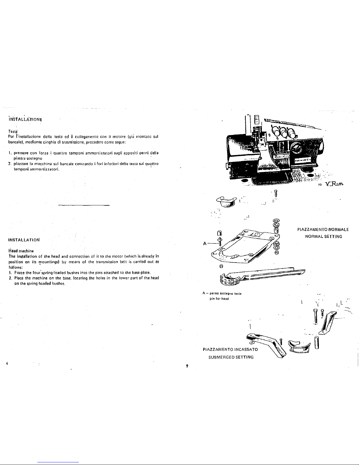
INSTALLATION
Head machine
the
lnslallation of the head and connection
of
it
to the motor !which
is
already
in
position
.on
its rpountings) by means of the transmission belt
is
carried oui
as
follows:
t.
Force the four' spring-loaded bushes
intO
the pins attached
to
the base-plate.
2.
Place
the machine
rih
the
bilse,
locating the holes
in
the lower part of the
head
on the spring-loaded hushos.
1
··,
'·
1,
A-
perno
sostegno testa
pin
for
head
PIAZZAMENTO INCASSATO
SUBMERGED SETTING
... J
..
·
..
·.·
TO
Y..Run.
PIAZZAMENTO NORMALE
NORMAL SETTING
I
~7
\.
1
...
···
....
~
Cirigitla
.' , .
Per·
ii coflcgamcnto motore . testa e
indispens<Jbile
impiegure UrHl cinghia
trapcioidale dalle
dimensioni indicate
in
rigUrti
1.
1. Montarc
Ia
cinghitt
di
trasmissione come
illustr<Jto
in
fig.
2.
2.
Registrare
Ia
tensiOne della cinghia agenda sullo snodo attacco motore,
in
modo
da non consentire
slittamenti,
rna
avendo cura di non tenderla eccessivamente
onde evitare sovraccarichi sugli alberi
delle pulegge e non compromettere
Ia
durata della cinghia stessa.
Si
ha
Ia
glusta tensione quando, premendo con
Ia
mana
al
centro
del
tratto Iibera
piU
lunge,
si
verifica
una
freccia,
cioEt
un
cedimento della cinghia, di 10·15 mm.
3.
Livcllare
Ia
testa della macchina affinchi!
Ia
cinghia
si
trovi
sui
piano normale
agli
assi
delle pulegge e
cioi!
lavori
al
centro delle lora
~ole.
Per
questa operazione
ngire
sui perni sostegno testa, avendo
cur
a di bloccare successivamente
gli
appo.
siti dadi.
4.
Monlare fnfine il coperchio protetione dnghia,
in
dotnzione
alia
testa.
N.B.
:
Perf
primi 20 giorni impiegare
Ia
macchina a velocitil ridotta, montarido
Ia
cinghia nella gala piccola della puleggia del motore,
al
fine
di
ottenere un perfetto
rodaggio che
assicurercl
Una
piU
lunga durata della macchina.
In
seguito spostare
Ia
clnghia nella gala grande della puleggia motore e quindi portarc
Ia
rnacchina
alia
vt:focit8
maSsima
conscn
til
a.
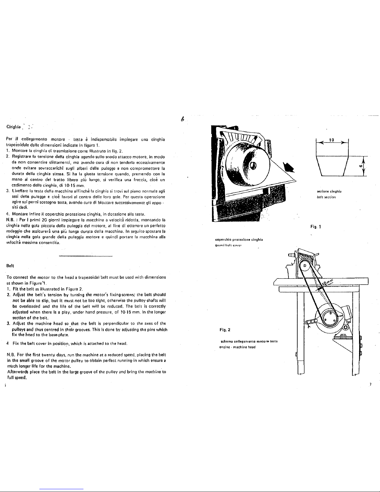
Bell
To
cOnnect the
motor
to the
head
a trapezoidal belt must
be
used with dimensions
us
shown
in
Figure '1.
1.
Fit the belt
as
illustrated
in
Figure 2.
2.
Adjust the belt's tension
by
turning the motor's fixing-screws; the belt should
not be able to slip, but
it
must not
be
too tight, otherwise
the
pulley-shafts
will
be overloaded
und
tl1e
life of the uelt
will
ue
reduced.
The
belt
is
correctly
adjusted when there
is
a play. under hand pressure, of 10·15
mm.
in
the longer
section of the
belt.
3. Adjust the machine tlead
so
ttlat the belt
is
perpendicular to the axes of the
pulleys and thus centred
In
th~ir
grooves.
This
is
done
by
adjusting the pins which
fix
the head to the base-plate.
4
Fix
the belt cover
in
positiofl, which
is
attached to
the
head.
N.B.
For the first twenty days, run the machine at a reduced speed, placing the belt
in
the
small
groove
of
the motor pulley
to
obtain perfect running·in which ensure a
much longer
life
for the machine.
Afterwards place the belt
In
the
large
groove of the pulley and bring the machine to
lull speed.
coperchio
protezione
cinghia
9~lilld
IJUIJ
C~IVlH
Fig.
2
s.chema collegamento motor&- testa
engine·
machine
head
10
iezione
clnghia
belt
section
Fig.
1
I
"'
7
..
RIF(JRf.JtrvuiNro
ouo
La
niacchina esce dagli stabilimenti senza lubrificante, per cui e necessaria prima
deii'Svviamento, prowedere
al
rifornimento
di
olio, impiegando
il
lubrificante
VR604 (Esso Standard Teressa 43),
ed
operando come segue:
1.
Far ruotare
il
piano
di
Iavere verso l'esterno e svitare
il
tappa
del
foro
di
rifornlmento sui coperchio cinematismi
(fig.
3).
2.
Per il rifur.,imento complete versare
nel
foro circa 600 gramrni
di
olio e
controllare
che
!'ago.
dell'indicatore
di live\lo (fig. 4·AI.
pasta
sulla
parte
anteriore della testa. raggiunga
Ia
posizione
MAX
(fig.
4); tenendo presente che il
movimento
dell'ago
ha
un
certo
ritardo
rispetto
all'aurnento di livel\o dell'olio
(si muove
dopa
che
sana
stati
versati circa i
2/3
della capacita della bacinella).
3. Riavvitare quindi
il
tappa e riportare il piano di lavoro nella
sua
posizione
normale.
4. Prima
di
avviare
Ia
macchina e consigliabile lubrificare con qualche goccia d'olio
Ia
barra
del
morsetto porta ago e
gli
snodi
del
crochet superiore.
5.
Fare funzienare
Ia
macchina a vuoto per circa 5 minuti, aumentando
progressivamente
Ia
velocit3 fino a portarla
da
1500
giri
al
minute
alia
velocit8
d'implego.
6.
Ourante il funzior1amente controllare
II
circuito di lubrificazione attraverso
Ia
spia trasparente del coperchio distribuzione olio, situate sotto il coperchio delle
tensioni
fig.
4.
lmportante:
La lancetta dell'indicatore live/to
Olio
non
deve
rnai
superare i due tratti
rossi
all'csterno dei pUnti
MIN e MAX,
perch~
net prime caso
Ia
lubririctrzione sarebbc
lni!ffi.clente,
nel secondo
sl
Potrebbero veHficare fuoruscite
di
olio.
LUBRICATION
The
machine
is
despached without oil and it
is
therefore necessary to
oil
before.
Use
VR604 (EssoStandard Teresso 43),1ollowing the procedure below:
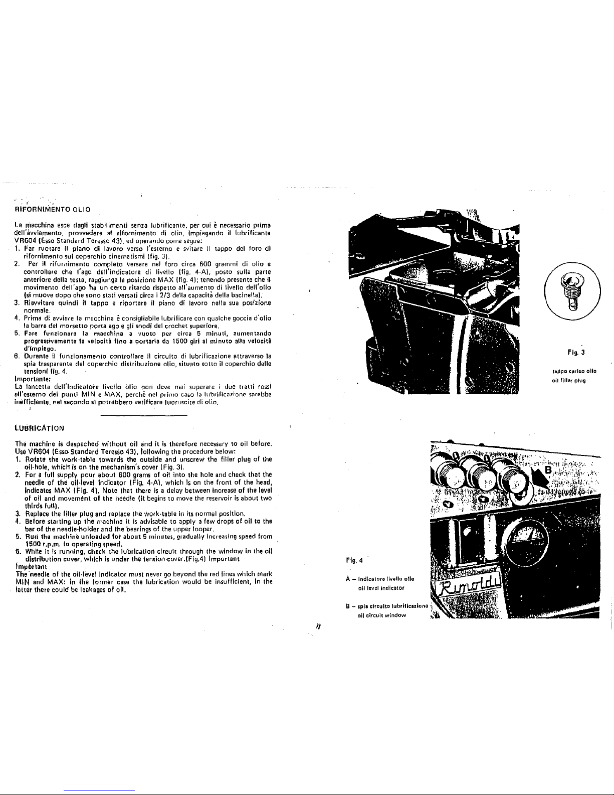
1.
Rotate the work·table towards the outside and unscrew the filler plug of the
oil· hole, which
is
on
the mechanism's cover (Fig. 3).
:i.
For a
full
supply pour about 600 grams of
oil
into the hole and check that the
needle of the oil·leve) Indicator (Fig, 4·A), which
is
on the front of the head,
Indicates
MAX
(Fig.
41.
Note that there
is
a delay between increase of the
level
of
oil
and movement
of
the needle
Ot
begins to
move
the reservoir
is
about two
thirds
full),
:l.
Replace ihe filler plug and replace the work·table
in
its normal position.
4.
Before starting up the machine
it
is
advisable to apply a few drops
of
oil
to
the
bar of the
needle·holder and the bearings of the upper looper.
5,
Rutl the machine uhloaded for about 5 minutes, gradually increasing speed from
1500 r.p.m. to operating speed.
6.
While
It
is
running, check the lubrication circuit through the window
In
the all
distribution cover, which
is
under the tension·cover.(Fig.4) Important
lmpbrtant .
The
·needle of the oil·level Indicator must never
go
beyond the red lines which mark
MIN
and
MAX:
in
the Iarmer case the lubrication would be insufficient,
In
the
latter there
could be leakages of all.
I/
Fig.
4
A - lndica1ore \lvello alia
oil
level
indicator
all circuit window
Fig.
3
taPpa car lea alia
oil
filler
plug
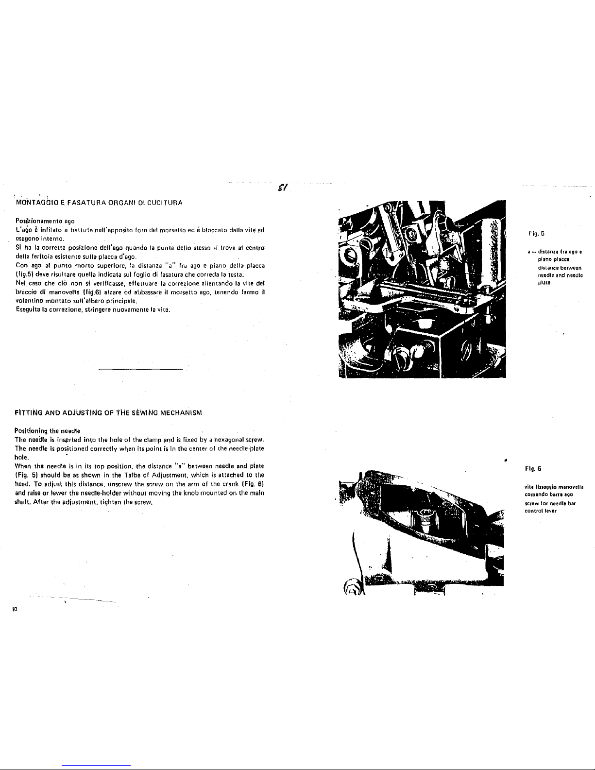
MONTAGG'IO
E FASATURA ORGANI
Dl
CUCITURA
Posizionamento
ago
L'CJQo e lnfilato a battuta
noll'
apposite
foro
del
morsetto
ed e b!occato
dalla vile ad
csagono interne.
Sl
ha
Ia
corretta posizione dell' ago quando
Ia
punta della stesso
si
trova
at
centro
della
feritoia esistente sulla placca d'ago.
Con
ago
a!
punta
marta
superiore,
Ia
distanza
"a"
fru
ago
e piano della placca
lfig.5J deve risultare
quell a indicata
sui
foglio
di
fasatura che correda
Ia
testa.
Nel_
case che
ciO
non
si
verificasse, effeltuare
Ia
corre~ione
allentando
Ia
vite
del
hraccio
eli
manovclla
{fiQ.61
alzare
Od
al.Jbassare
il
morsetto
ago,
tenendo
fermo
i1
volant
ina
manta
to
suil' albero principal e.
Escguita
ia
corrczione, stringere nuovamente
Ia
vite.
FITTING
AND
ADjUstiNG
OF
tHE
SEWING
MECHANISM
Positioning the needle
The needle
Is
lnS~>rted
into the hole of the clamp and
is
fixed
by
a hexagonal screw.
The needle
is
positioned correctly
w~en
its point
is
In
the center of the necdle·plate
hole. •
When the needle
is
in its
top
position, the distance 1'a"
between needle and piate
(Fig.
51
should be
as
shown
in
the Talbe
of
Adjustment, which
is
attached to the
head. To adjust this distance, unscrew the screw on the arm of the crank
(Fig.
6)
and
raise
or !ewer the needle·holdet without moving the knob mounted on the main
shaft. After the adjustment, tighten the screw.
10
t'l
•
Fig.
5
a-
distanu
ha
ago
e
piano placca
distance
between
needle and needle
plate
Fig.
6
vha fluagglo manovella
comando barr1
ago
screw
for
needle bar
control lever
 Loading...