

Page 1

User Guide RIGOL
Publication number DG3-070728
March 2007
DG3000 Series Function/Arbitrary
Waveform Generator
© Copyright RIGOL Technologies, Inc. 2007
All Rights Reserved
Page 2

Page 3

RIGOL
z Copyright © RIGOL TECHNOLOGIES, INC. 2007 All Rights Reserved.
z RIGOL products are protected by patent law in and outside of P.R. China.
z Information in this publication replaces all that in previously corresponding materials.
z RIGOL Technologies, Inc. reserves the right to modify or change part of or all the
specifications and pricing policies at company’s sole decision.
NOTE: RIGOL is the registered trademark of RIGOL TECHNOLOGIES, INC.
© Copyright RIGOL Technologies, Inc. 2007. I
User Guide for DG3000 Series
Page 4

RIGOL
Safety Notices
Review the following safety precautions carefully before operating the instrument to avoid
any personal injury or damage to the instrument or products connected to it.
To avoid potential hazards, use the instrument in a manner only as specified by this user
manual.
The instrument should be serviced by qualified personnel only.
To Avoid Fire or Personal Injury
Use proper power cord. Only the dedicated power cord of the products approved by the
State should be used.
Connect and Disconnect accessories properly. Do not connect or disconnect probes or
test leads while they are connected to a voltage source.
Ground the instrument This generator is grounded through the protective earthing
conductor of the power cord. To avoid electric shock, the grounding conductor must be
connected to earth ground. Maker sure the instrument is properly grounded before
connecting the input or output terminals.
Connect the probe properly. The probes’ ground terminals are at the same voltage level
with earth terminal of the instrument. Do not connect the ground terminals to a high voltage.
Observe All Terminal Ratings. To avoid fire or shock, observe all ratings and marks on the
instrument. Follow the user manual for further rating information before making connections
to the instrument.
Do not operate without Covers. Do not operate your generator with covers or panels
removed.
Use Proper Fuse. Only use the fuse type and rating specified for this product.
Avoid Circuit or Wire Exposure. Do not touch exposed connections or components when
II © Copyright RIGOL Technologies, Inc. 2007.
User Guide for DG3000 Series
Page 5

RIGOL
they are on.
Do not operate with suspected failures. If you suspect damage with this product, have it
inspected by qualified service personnel before further operations.
Provide Proper Ventilation.
Do not operate in wet/damp conditions
Do not operate in an explosive atmosphere
Keep product surfaces clean and dry
© Copyright RIGOL Technologies, Inc. 2007. III
User Guide for DG3000 Series
Page 6
RIGOL
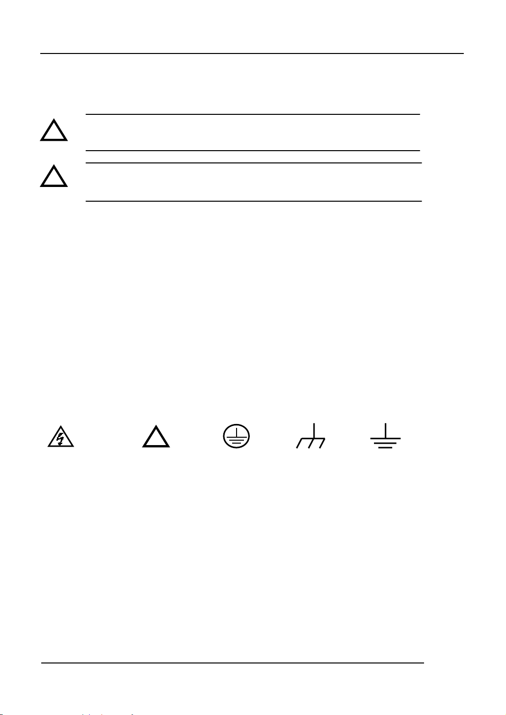
Safety Terms and Symbols
Terms in This Manual. These terms may appear in this manual:
!
!
Terms on the Product: These terms may appear on the product:
DANGER indicates an injury hazard that may be immediately accessible.
WARNING indicates an injury hazard that may be not immediately accessible.
CAUTION indicates that a potential damage to the instrument or other property might occur.
Symbols on the Product: These symbols may appear on the Instrument:
Hazardous Refer to Protective
Voltage Instructions
WARNING: Warning statements identify conditions or practices that could result in
injury or loss of life.
CAUTION: Caution statements identify conditions or practices that could result in
damage to this product or other property.
!
Test
Grounding
Terminal
earth terminal
Grounding
Terminal
of Chassis
IV © Copyright RIGOL Technologies, Inc. 2007.
User Guide for DG3000 Series
Page 7

RIGOL
Rigol DG3000 Generator at a Glance
The book covers the following 3 types of DG3000 Series Function/ Arbitrary Waveform
Generators:
DG3121A、DG3101A、DG3061A
RIGOL DG3000 Series Function/ Arbitrary Waveform Generator apply the DDS technology,
which can provide stable, high-precision, pure and low distortion sine signal. It also can
provide 120MHz square waveform with fast rising or falling edges. Its combination of
excellent system features, easiness in usage and versatile functions makes this generator a
perfect solution for your job now and in the future.
DG3000 Series Function/ Arbitrary Waveform Generator have clear and simple Front-Panel.
The user-friendly panel layout and instructions, versatile terminals, direct graph interface,
built-in instructions and help system has greatly simplified the operation process, with the
help of which, users do not have to spend a great deal of time learning and familiarizing the
operation of the generator before they can use it proficiently. The built-in AM, FM, PM, and
FSK modulation functions generate modulated waveform at ease, without the help of a
separate modulating source. USB I/O is a standard accessory, while LAN and GPIB are
Optional. Remote instructions meet the SCPI specification requirements.
From the characteristics and specifications given below, you will understand how DG3000 can
satisfy your measurement requirements.
z 16+2 channels digital output module (Optional) together with the analogue channel can
rebuild the most commonly used mixed signal in daily practice.
z Applying DDS technology provides precise, stable and low distortion output signal.
z 4.0’ QVGA color LED display.
z 300MSa/s sampling rate, 14-bit resolution.
z Frequency characteristics:
Sine/ Square: 1µHz to 120 MHz
Ramp: 1µHz to 1 MHz
Pulse: 500µHz to 50MHz
White Noise:10MHz bandwidth (-3dB)
Arbitrary:1μHz to 25MHz
z 10 standard waveforms:
© Copyright RIGOL Technologies, Inc. 2007. V
User Guide for DG3000 Series
Page 8

RIGOL
Sine, Square, Ramp, Pulse, Noise, Sinc, Exponential Rise, Exponential Fall, Cardiac and
DC.
z Self-definable Arbitrary waveform.
z Multiple modulation function, various modulated waveform: AM, FM, PM, FSK, PWM,
SWEEP and Burst.
z Multiple I/O: External Modulation Source, External 10 MHz Reference Input, External
trigger source, waveform output, synchronous signal output, Internal 10 MHz Reference
output.
z Support USB storage device. Software Updating could also be performed using USB
devices.
z Utmost 1M sample points of internal waveform depth, which can rebuild or simulate any
complex waveform.
z Remote control is realized using the LAN.
Support 10/100M LAN. Users can remotely visit and control signal generation through
web browser.
z Multiple interfaces: USB Host & Device, RS-232, GPIB (IEEE-488), LAN.
z Support the seamless connection of DS1000 Series Digital Oscilloscopes; can directly
read and rebuild the stored waveform in the oscilloscopes.
z Graph interface which shows the signal setting directly.
z 10 languages user interface and built-in help system.
z Support Chinese/ English Input.
VI © Copyright RIGOL Technologies, Inc. 2007.
User Guide for DG3000 Series
Page 9

RIGOL
Content
Safety Notices .....................................................................................................................................II
Rigol DG3000 Generator at a Glance...............................................................................................V
Chapter 1 : Getting Start....................................................................................................... 1-1
General Inspection .......................................................................................................................... 1-2
Handle Adjustment.......................................................................................................................... 1-3
The Front/Rear Panel...................................................................................................................... 1-4
To Set a Waveform.......................................................................................................................... 1-8
To Set Modulate/ Sweep/Burst.................................................................................................... 1-12
To Set Trigger/Output................................................................................................................... 1-15
To Use Digital Input ......................................................................................................................1-16
To Use Store/Utility/Help Function.............................................................................................. 1-17
Chapter 2 : Operating Your Generator ............................................................................. 2-1
To Set Sine Signals.......................................................................................................................... 2-2
To Set Square Signals ..................................................................................................................... 2-7
To Set Ramp Signals .....................................................................................................................2-10
To Set Pulse Signals ...................................................................................................................... 2-13
To Set Noise Signals...................................................................................................................... 2-17
To Set Arbitrary Signals................................................................................................................ 2-19
To Generate the Modulated Waveform ...................................................................................... 2-32
To Generate Sweep....................................................................................................................... 2-42
To Generate Burst ......................................................................................................................... 2-46
To Store and Recall .......................................................................................................................2-50
To Set the Utility Function............................................................................................................ 2-64
How to Use the Built-in Help System.......................................................................................... 2-91
Chapter 3 : Application & Examples.................................................................................. 3-1
Example 1: To generate a Sine Wave ........................................................................................... 3-2
Example 2: To generate a Square Wave ......................................................................................3-3
Example 3: To generate a Ramp Wave ........................................................................................ 3-4
Example 4: To generate a Pulse Wave ......................................................................................... 3-5
Example 5: To generate a Noise Wave......................................................................................... 3-7
Example 6: To generate Arbitrary Waveform .............................................................................. 3-8
Example 7: To Generate an Arbitrary Waveform ...................................................................... 3-10
Example 8: To Generate an AM Waveform ................................................................................3-12
© Copyright RIGOL Technologies, Inc. 2007. VII
User Guide for DG3000 Series
Page 10

RIGOL
Example 9: To Generate an FSK Waveform............................................................................... 3-14
Example 10: To Generate a PWM waveform ............................................................................. 3-16
Example 11: To Generate a Linear Sweep Waveform ..............................................................3-18
Example 12: To Generate a Burst Waveform ............................................................................3-20
Chapter 4 : Prompt messages & troubleshooting ........................................................4-1
Prompting Message ......................................................................................................................... 4-1
Troubleshooting .............................................................................................................................4-15
Chapter 5 : Support & Service ............................................................................................. 5-1
Chapter 6 : Appendix ..............................................................................................................6-1
Appendix A: Specifications .............................................................................................................6-1
Appendix B: DG3000 Series Accessories...................................................................................... 6-8
Appendix C: General Care and Cleaning ...................................................................................... 6-9
VIII © Copyright RIGOL Technologies, Inc. 2007.
User Guide for DG3000 Series
Page 11

Chapter 1 : Getting Start
This chapter covers the following topics:
General Inspection
Handle Adjustment
The Front/rear Panel
To Se t a Wa v e f or m
To Set Modulation/Sweep/Burst
To Set Trigger/Output
To Use Digital Input
To Use Store/Utility/Help Function
RIGOL
© Copyright RIGOL Technologies, Inc. 2007. 1-1
User Guide for DG3000 Series
Page 12

RIGOL
General Inspection
When you get a new DG3000 Series Function/ Arbitrary Waveform Generator, you
are suggested to take the following steps to inspect the instrument.
1. Inspect the shipping container for damage.
Keep the damaged shipping container or cushioning material until the contents
of the shipment have been checked for completeness and the instrument been
checked mechanically and electrically.
2. Check the accessories.
Accessories supplied with the instrument are listed in "Accessories" in the front of
this manual.
If the contents are incomplete or damaged, please notify your RIGOL Sales
Representative.
3. Inspect the instrument.
In case any mechanical damage or defect, or if the instrument does not operate
properly or pass performance tests, notify your RIGOL Sales Representative.
If the shipping container is damaged, or the cushioning materials show signs of
stress, notify the carrier as well as your RIGOL sales office. Keep the shipping
materials for the carrier’s inspection.
RIGOL offices will arrange for repair or replacement at RIGOL’s option without
waiting for claim settlement.
1-2 © Copyright RIGOL Technologies, Inc. 2007.
User Guide for DG3000 Series
Page 13
RIGOL
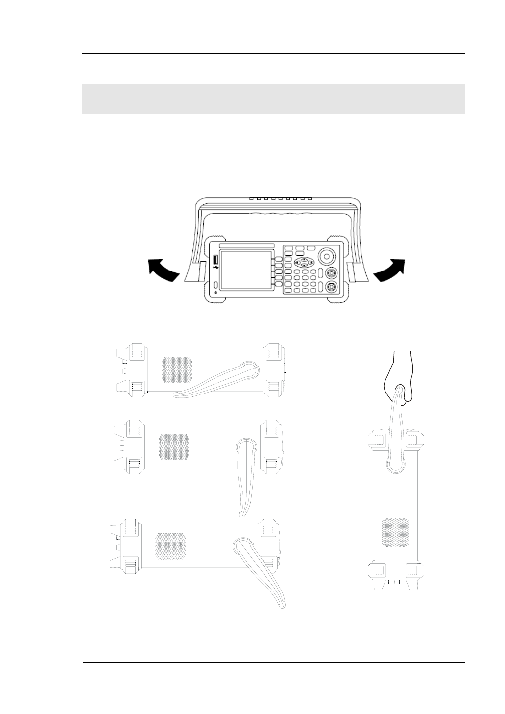
Handle Adjustment
To adjust the handle position of DG3000 Function/ Arbitrary Waveform Generator,
please grip the handle by the sides and pull it outward. Then, make the handle rotate
to the desired position. The operating methods are shown in the graphs below 1-1,
1-2, 1-3.
Figure 1-1 Adjust the handle
Figure 1-2 Figure 1-3
Viewing Positions Carrying Position
© Copyright RIGOL Technologies, Inc. 2007. 1-3
User Guide for DG3000 Series
Page 14
RIGOL
The Front/Rear Panel
When you get a new DG3000 Series Function/ Arbitrary Waveform Generator, first
you need to clear how to operate the front/ Rear panel correctly. This chapter will
make a brief introduction and description for the operation and functions of the
Front/ Rear Panel.
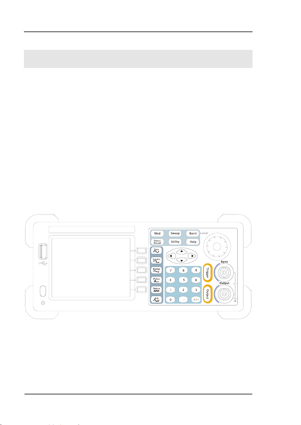
The Front Panel at a Glance
The DG3000 Series Function/ Arbitrary Waveform Generator has clear and simple
front panel. See Figure 1-4 and 1-5. The Front Panel has a knob and functional keys.
The 5 blue grey buttons on the right side of the screen are menu buttons (named F1
to F5 from up to down) with the help of which, you can enter different functions
menu or have direct specific applications. The signal input and output interfaces are
set at the rear panel which can help generating multiple arbitrary waveforms. The
various BUS interfaces can meet the need of the multiple interface communications.
Figure 1-4
DG3000 Series Function/ Arbitrary Waveform Generator Front Panel
1-4 © Copyright RIGOL Technologies, Inc. 2007.
User Guide for DG3000 Series
Page 15
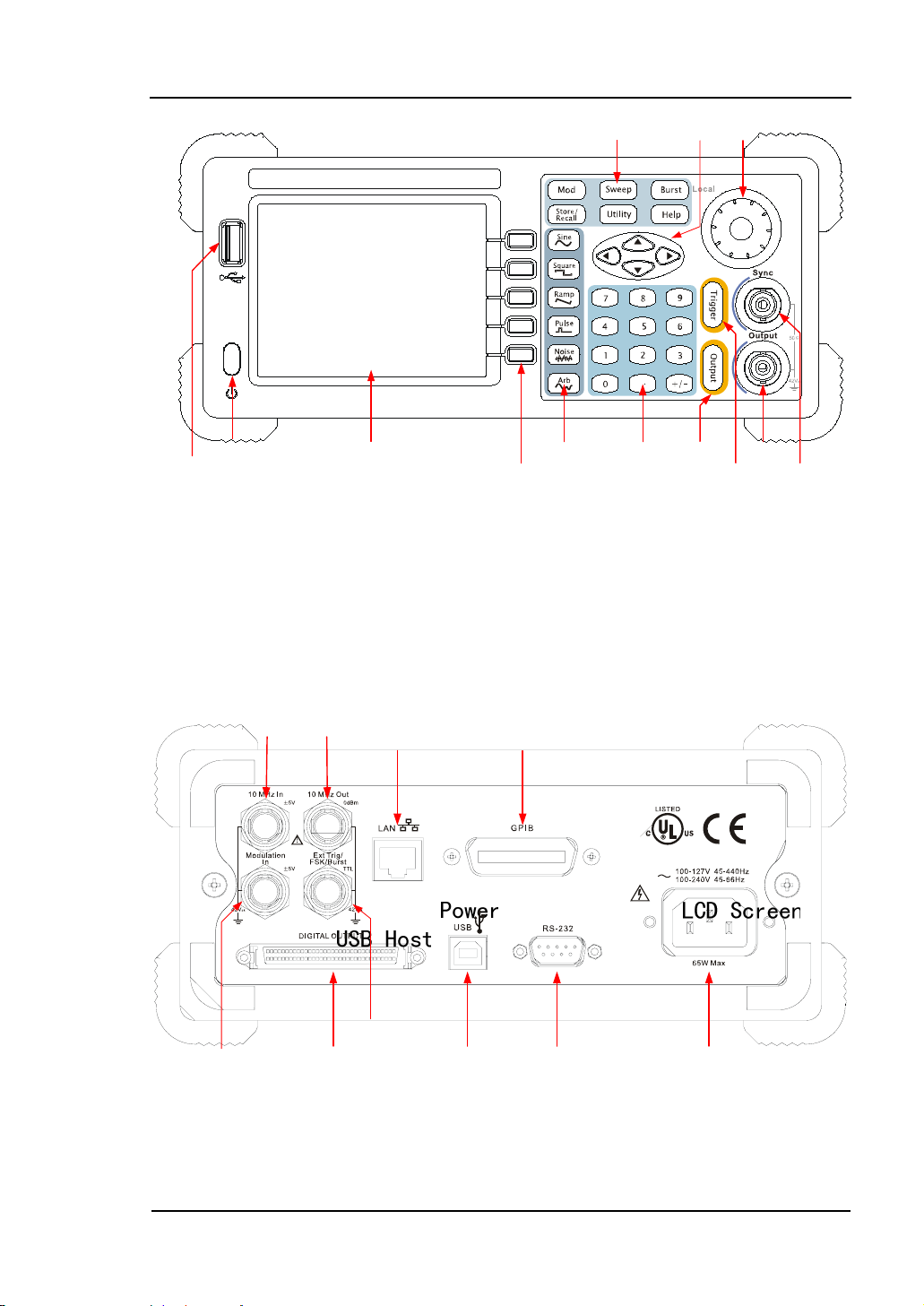
Figure 1-5
DG3000 Series Function/ Arbitrary Waveform Generator Front Panel Operation
Instruction
The Rear Panel at a Glance
RIGOL
Figure 1-6
DG3000 Series Function/ Arbitrary Waveform Generator Rear Panel
© Copyright RIGOL Technologies, Inc. 2007. 1-5
User Guide for DG3000 Series
Page 16
RIGOL
N
Waveform
display
window
Parameter
Display and
editing
Window
Parameter
ame
Value
Operation Menu:
Different
functions have
different menus
Parameter
Value
Unit
Figure 1-7
Display Interface (Sine Wave is the default display signal)
1-6 © Copyright RIGOL Technologies, Inc. 2007.
User Guide for DG3000 Series
Page 17
RIGOL
Character definitions in this User Manual:
The signs for buttons in this book are the same as the panel buttons. Please note
that, the signs for the functional buttons on the operation panel are represented by
squared words, such as Sine, which represents the transparent functional key with
Sine on it on the front panel, while the menu buttons are represented by darkened
words such as Freq, which means the “Frequency” option in the Sine menu.
Note:The main Output and Sync Channels are located in the front panel,
!
which only allow signal output. If they are used as signal input channels,
they will be burned and lead to instrument malfunction.
© Copyright RIGOL Technologies, Inc. 2007. 1-7
User Guide for DG3000 Series
Page 18
RIGOL
To Set a Waveform
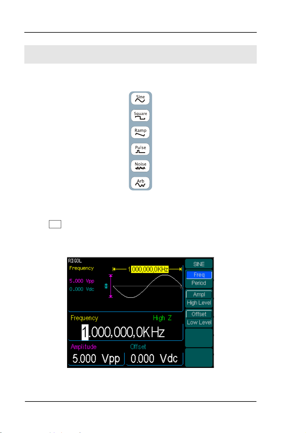
On the operation panel, there is a set of buttons with waveform icon. See Figure 1-8.
The exercise below will help you familiarize with the waveform selection settings.
Figure 1-8
Waveform Selection Buttons
1. Press Sine button and the waveform window will display sine waveform. DG3000
Series Generator can generate Sine signal with a frequency from 1μHz to 120MHz.
Set Frequency/Period, Amplitude/ High Level, Offset/ Low level, sine signal with
different parameters can be generated.
Figure 1-9
Sine Signal display interface
1-8 © Copyright RIGOL Technologies, Inc. 2007.
User Guide for DG3000 Series
Page 19
RIGOL
As shown in Figure 1-9, the default signal parameters are: 1 kHz Frequency, 5.0 Vpp
Amplitude and 0Vdc Offset.
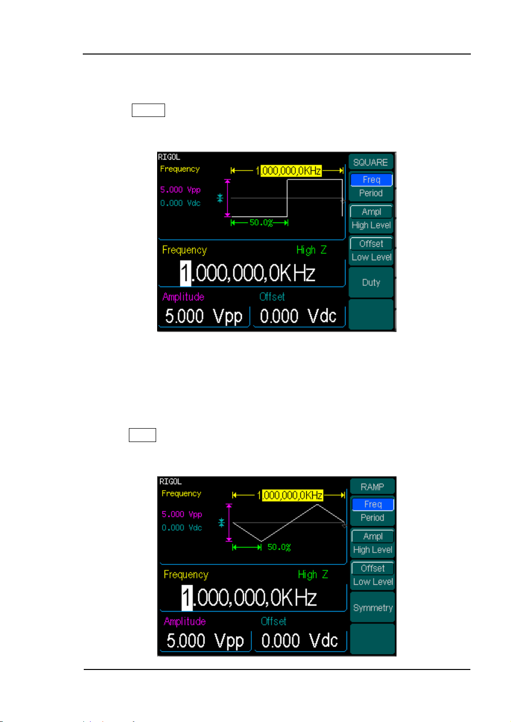
2. Press Square button, and the waveform window displays square waveform.
DG3000 Series Generator can generate Square signal with a frequency of from 1μHz
to 120MHz and variable duty cycle.
Figure 1-10
Square Signal display interface
As shown in Figure 1-10, the default signal parameters are: 1kHz Frequency, 5.0 Vpp
Amplitude, 0Vdc Offset and 50% Duty Cycle.
3. Press Ramp button, and the waveform window displays ramp waveform. DG3000
Series Generator can generate Ramp signal with a frequency of from 1μHz to 1 MHz
and variable Symmetry.
© Copyright RIGOL Technologies, Inc. 2007. 1-9
User Guide for DG3000 Series
Page 20
RIGOL
Figure 1-11
Ramp Signal display interface
As shown in Figure 1-11, the default signal parameters are: 1kHz Frequency, 5.0 Vpp
Amplitude, 0Vdc Offset and 50% Symmetry.
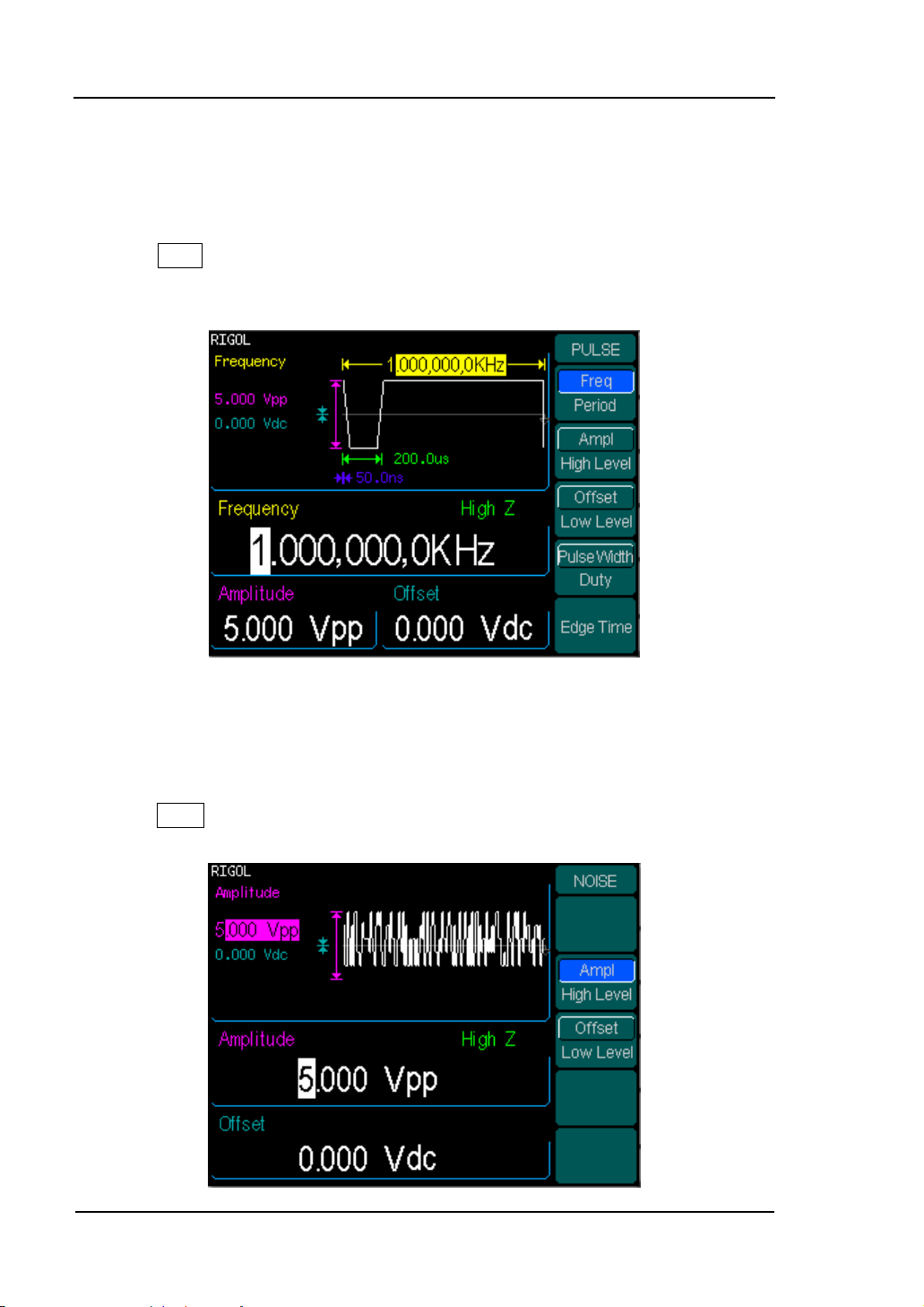
4. Press Pulse button, and the waveform window displays pulse waveform. DG3000
Series Generator can generate Pulse signal with a frequency of from 500μHz to 50
MHz and variable Pulse Width and Edge Time.
Figure 1-12
Pulse Signal display interface
As shown in Figure 1-12, the default signal parameters are: 1kHz Frequency, 5.0 Vpp
Amplitude, 0Vdc Offset, 200μs Pulse Width and 50ns Edge Time.
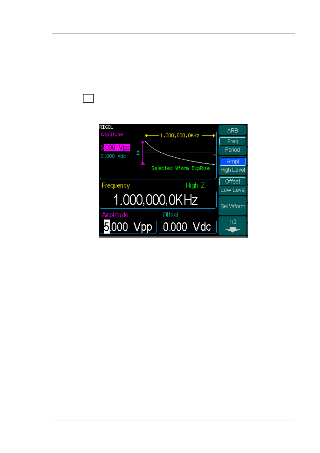
5. Press Noise button, and the waveform window displays noise waveform. DG3000
Series Generator can generate Noise signal with a Band Width up to 10 MHz.
1-10 © Copyright RIGOL Technologies, Inc. 2007.
User Guide for DG3000 Series
Page 21
RIGOL
Figure 1-13
Noise Signal display interface
As shown in Figure 1-13, the default signal parameters are: 5.0 Vpp Amplitude and
0Vdc Offset.
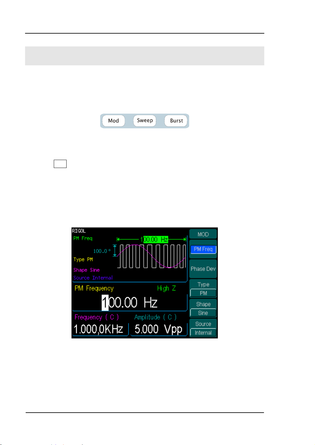
6. Press Arb button, and the waveform window displays arbitrary waveform.
DG3000 Series Generator can generate repeatable arbitrary waveform signals with at
most 512K points and 25MHz frequency.
Figure 1-14
Arbitrary waveform Signal display interface
As shown in Figure 1-14, the default Exponential Rise Signal parameters are: 1kHz
Frequency, 5.0 Vpp Amplitude and 0Vdc Offset.
© Copyright RIGOL Technologies, Inc. 2007. 1-11
User Guide for DG3000 Series
Page 22
RIGOL
To Set Modulate/ Sweep/Burst
As shown in Figure 1-15, there are three buttons on the front panel, which are used
for Modulating, sweeping and bursting settings. The instructions below will help you
familiarize with the setting of these functions.
Figure 1-15
Modulate/ Sweep/ Burst button
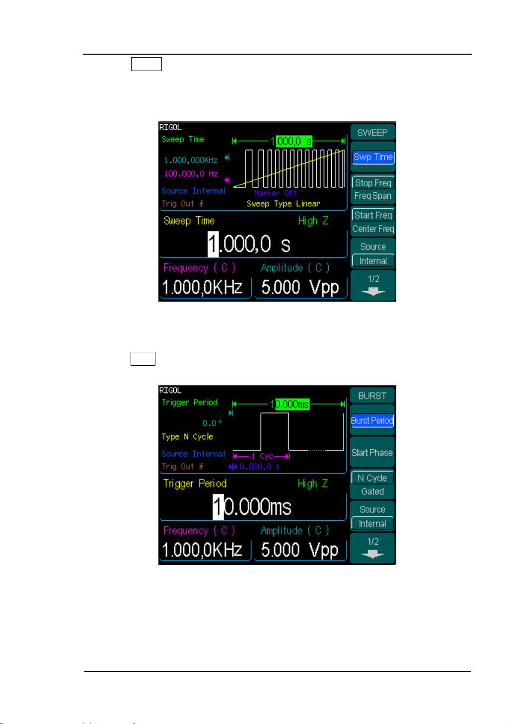
1. Press Mod button, and the Modulated waveforms will be generated.
The modulated waveform can be changed by modifying the parameters such as Type,
Internal/ external Modulation, Depth, Frequency, Waveform, etc.
DG3000 Series can modulate waveform using AM, FM, PM, and FSK. Sine, Square,
Ramp or Arbitrary waveforms can be modulated (Pulse, Noise and DC can not be
modulated).
Figure 1-16
Modulated Waveform Signal display interface
1-12 © Copyright RIGOL Technologies, Inc. 2007.
User Guide for DG3000 Series
Page 23
RIGOL
2. Press Sweep button, Sine, Square, Ramp or Arbitrary waveform can be swept
(Pulse, Noise and DC can not be swept).
In the Sweep Mode, DG3000 Series generate signal with variable frequencies.
Figure 1-17
Sweep Waveform Signal display interface
3. Press Burst button, Burst for Sine, Square, Ramp, Pulse or Arbitrary waveform
can be generated (Noise can only be used in the gated Burst).
Figure 1-18
Burst Waveform Signal display interface
© Copyright RIGOL Technologies, Inc. 2007. 1-13
User Guide for DG3000 Series
Page 24

RIGOL
Term Explanation
Burst:Output Waveforms with set cycle times
Burst can last for certain times of waveform cycle (N-Cycle Burst) or be controlled by
external gated signals (Gated Burst). Burst applies to all kinds of waveforms, but
noise can only be used in gated burst.
1-14 © Copyright RIGOL Technologies, Inc. 2007.
User Guide for DG3000 Series
Page 25
RIGOL
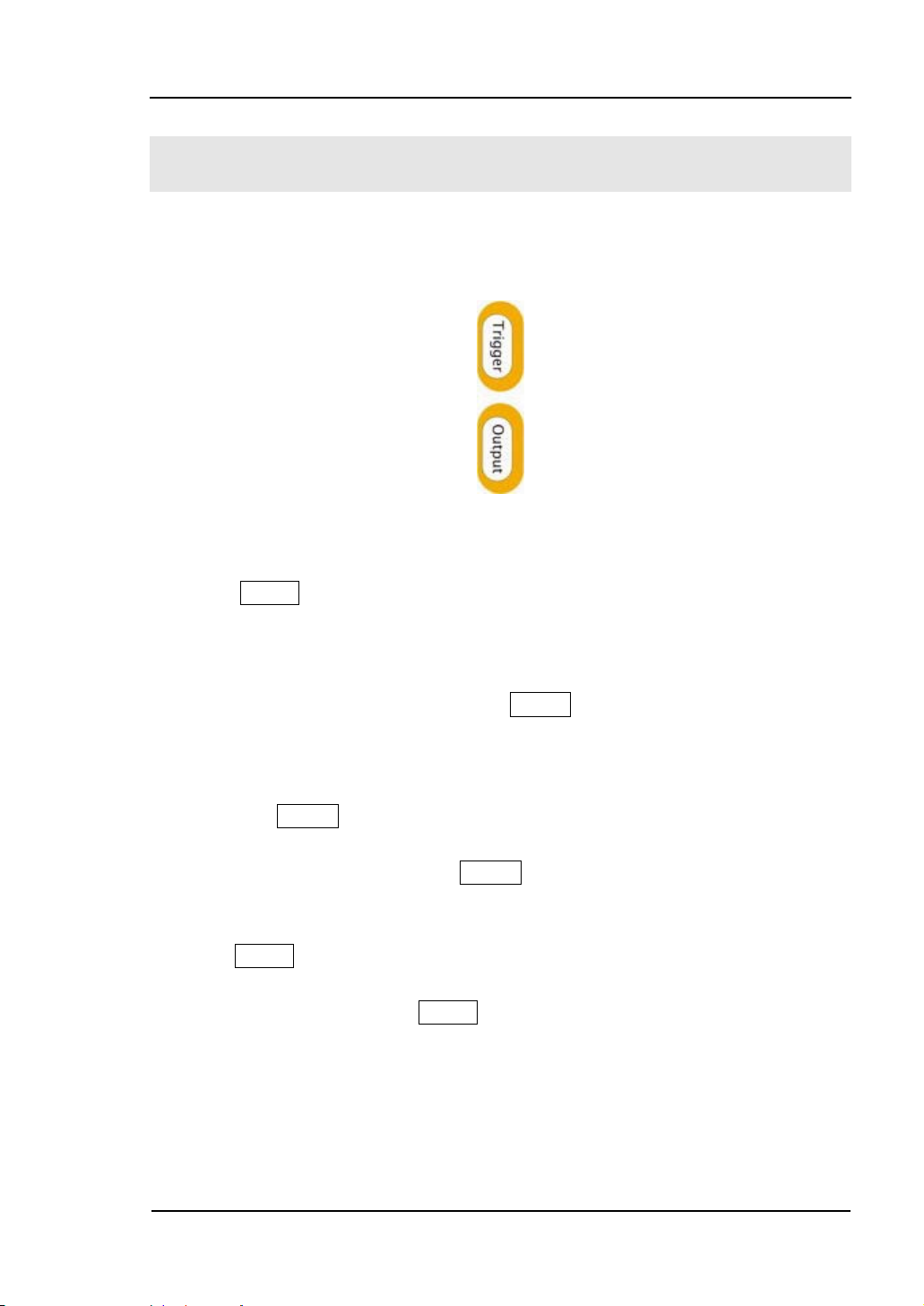
To Set Trigger/Output
As shown in Figure 1-19, there are two buttons on the right side of the operation
panel, which are used to set Trigger and Output Control. The instruction below will
help you familiarize with these functions.
Figure 1-19
Trigger/ Output Button
1. Press Trigger Button, choose internal/ external or manual Trigger (Manual
Trigger can only be used in Sweep and N-Cycle Burst)
· The default setting for Trigger is “Internal”. In this mode, when the Sweep
or Burst Mode is also selected, the Generator will generate burst
continuously. At this time, press Trigger button, the instrument will shift
from the “Automatic” Trigger mode into “Manual” Trigger mode.
· When the generator uses the” External” Trigger Mode, if the Sweep or the
Burst Mode is selected, signal will be generated continuously. At this time,
press Trigger button, the instrument state will not change, and it will show
“The instrument has already been triggered”.
· Every time you press the Trigger button, “Manual” Trigger will start a
sweep or generate a burst. Press the button again, and the generator will
be triggered again.
2. Press Output Button, activate or deactivate the output signal.
If an overload message is shown, disconnect the external equipment from the
output terminals and press Output button, reactivate the output terminal.
© Copyright RIGOL Technologies, Inc. 2007. 1-15
User Guide for DG3000 Series
Page 26
RIGOL
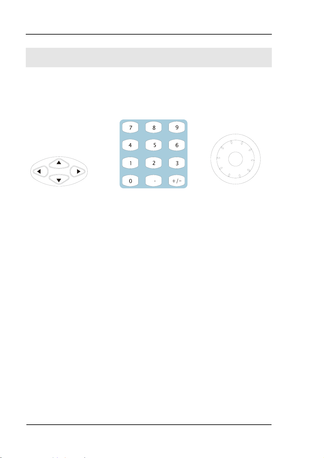
To Use Digital Input
As shown in Figure 1-20, there are two sets of buttons on the operation panel, which
are direction button, the knob and the keypad. The instruction below will help you
familiarize with the Digital Input Function.
(1)direction key (2)keypad (3)knob
Figure 1-20
Front Panel Digital Input
1. The up and down keys are used to shift the parameters and the left and right
keys are used to shift digits.
2. Keypad is used to directly set the parameters value
3. Knob is used to change a signal digit value whose range is 0~9. Clockwise to
increase.
1-16 © Copyright RIGOL Technologies, Inc. 2007.
User Guide for DG3000 Series
Page 27

RIGOL
To Use Store/Utility/Help Function
As shown in Figure 1-21, there are three buttons on the operation panel, which are
used to call the store/recall, utility and help function. The instruction below will help
you familiarize with these Functions.
Figure 1-21
Store/Recall, Utility and Help Button
1. The Store/Recall Button is used to store waveform data and configure
information.
2. The Utility Button is used to set the auxiliary system function, change the output
configure parameters, interface setting, system setting information or perform
the instrument self-test and read the calibration information, etc.
3. The Help Button is used to read the help information.
Operation Instruction
To get help on :
To get help on any key of the front panel, press and hold on that key for 1 second
and the help message will appear.
© Copyright RIGOL Technologies, Inc. 2007. 1-17
User Guide for DG3000 Series
Page 28

Page 29

RIGOL
Chapter 2 : Operating Your Generator
By now you have got a brief understanding about DG3000 series with the front/rear
panel, every function control area and keys. You should also know how to set your
function/ arbitrary waveform generator for your usage. If you are not familiar with
these operations, you are suggested to read Chapter One “Getting Started” again.
This chapter covers the topics listed below:
This chapter covers the following topics:
Setting Sine Signal ( Sine )
Setting Square Signal ( Square )
Setting Ramp Signal ( Ramp )
Setting Pulse Signal ( Pulse )
Setting Noise Signal ( Noise )
Setting Arb Signal ( Arb )
Output Modulated Signal ( Mod )
Output Sweep Signal ( Sweep )
Output Burst Signal ( Burst )
Trigger ( Trigger )
Store/Recall ( Store/Recall )
Utility Setting ( Utility )
Help System ( Help )
You are suggested to read this chapter carefully so as to understand
DG3000 Series Generator‘s versatile waveform setting Functions and more
operation methods.
© Copyright RIGOL Technologies, Inc. 2007. 2-1
User Guide for DG3000 Series
Page 30
RIGOL
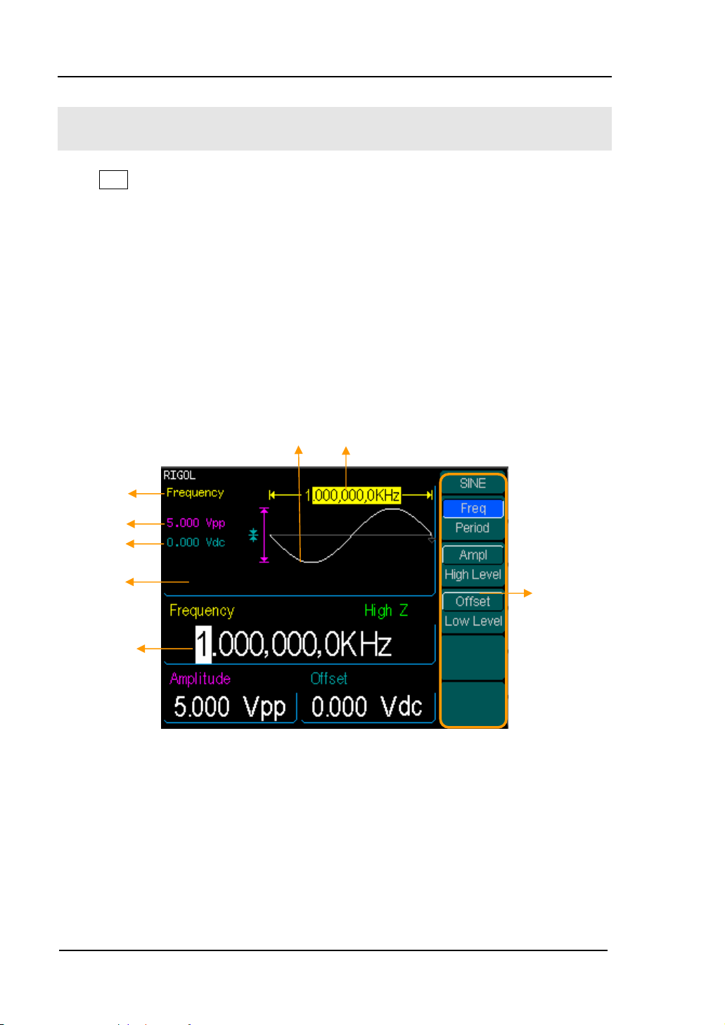
To Set Sine Signals
Press Sine Button to call the Sine operation. The output Sine waveform parameters
are set using the Sine operation menu.
The parameters for Sine waveforms are: Frequency/ Period, Amplitude/ High Level,
Offset/ Low Level. Different Sine Signals are generated by modifying these
parameters. The parameter value in the waveform display window is the same as that
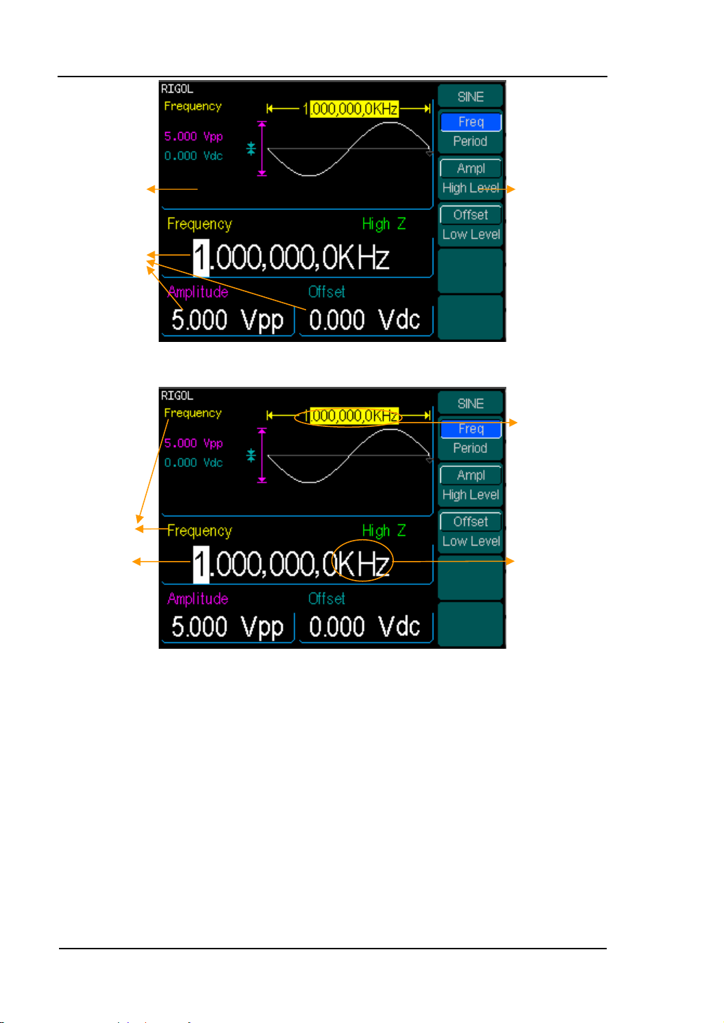
of in the parameter display window. As is shown in Figure 2-1, in the soft key menu,
select Freq. Cursor is located in the frequency parameter area in the parameter
display window. Users can set the frequency value right here. In the waveform
display window, the parameter type in the left corner is frequency, the value of which
is displayed in darkened color.
Current
Parameter
Amplitude
Offset
Waveform display
Frequency
value
Waveform
Frequ
Figure 2-1
Sine Signal Parameter display Interface
Operation
Men
Control
function
with the
soft keys
u:
2-2 © Copyright RIGOL Technologies, Inc. 2007.
User Guide for DG3000 Series
Page 31

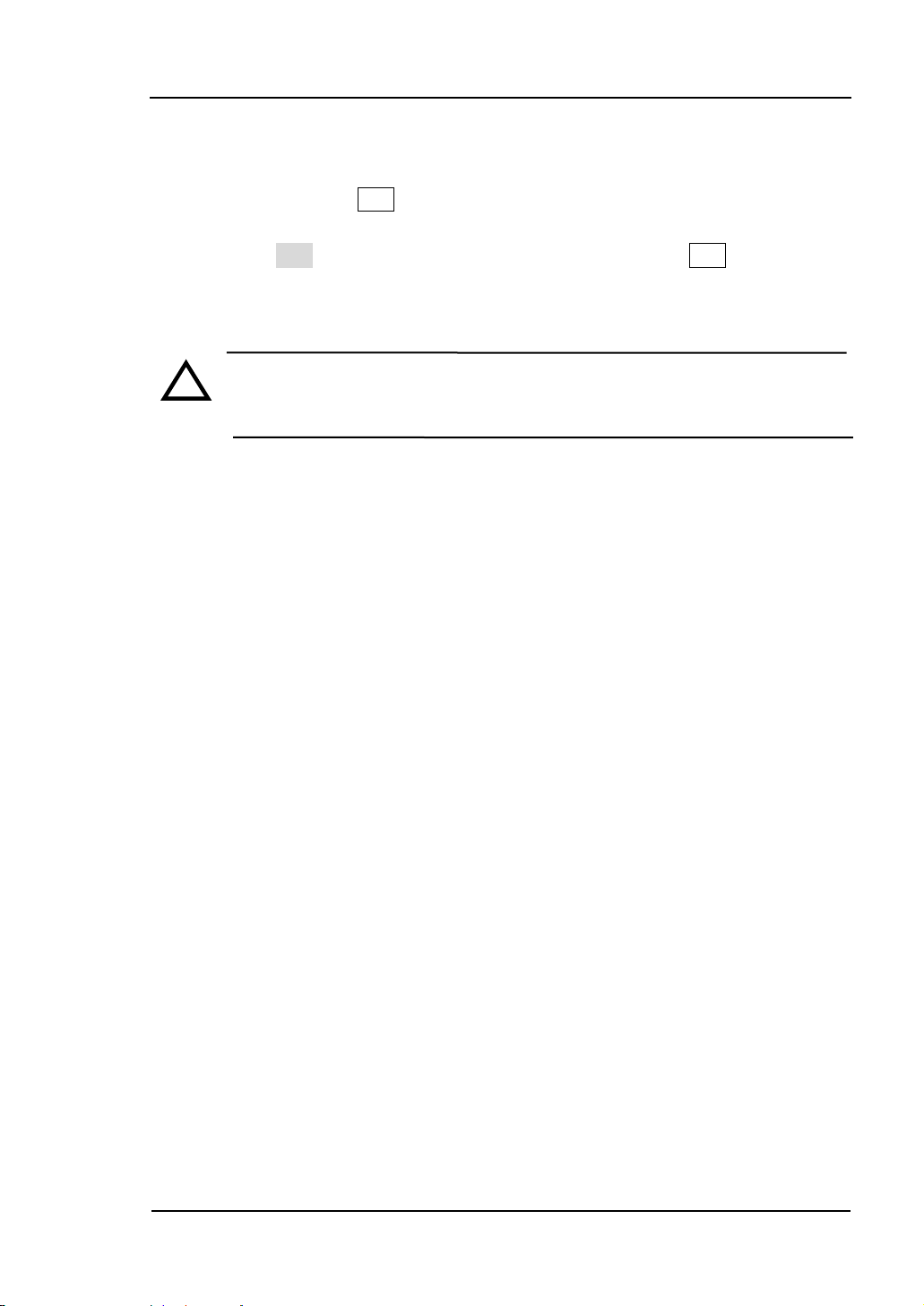
Figure 2-2 Table 2-1 Sine waveform menu
RIGOL
Function
menu
Settings Explanations
Setting the signal’s frequency or
Freq
Period
period; the current parameter will
switch at a second press.
Setting the signal’s Amplitude or
Ampl
High Level
High Level; the current parameter
will switch at a second press.
Offset
Low Level
Setting the signal’s Offset or Low
Level; the current parameter will
switch at a second press
Instructions
The parameter type in the top left corner of Figure 2-2 is the current parameter,
whose value will be displayed in darkened color.
© Copyright RIGOL Technologies, Inc. 2007. 2-3
User Guide for DG3000 Series
Page 32

RIGOL
To Set the Output Frequency/Period
(1). Press Sine Æ Freq ,to set the frequency parameter.
The frequency shown on the screen when the instrument is powered is the default
value or the set value beforehand. When setting the function, if the current value is
valid for the new waveform, it will be used sequentially. If you want to set the period
for the waveform, press Freq/Period button again, to switch to the Period parameter
(The current operation is displayed in inverse color).
(2). Input the desired frequency.
Use the keypad to input the parameter value directly, and press the corresponding
button to select the parameter unit. Or you can use the direction button to select the
digit you want to edit, and then use the knob to change its value.
Current
Parameter:
Frequency
Figure 2-3
Setting the Frequency
Instruction:
When using the keypad to enter the digit, you can use the Left direction button to
move the cursor backward and delete or change the value of the previous digit.
2-4 © Copyright RIGOL Technologies, Inc. 2007.
User Guide for DG3000 Series
Page 33

RIGOL
To Set the Output Amplitude
(1). Press Sine Æ Ampl ,to set the amplitude.
The amplitude shown on the screen when the instrument is powered is the default
value or the set value beforehand. When changing the function, if the current value is
valid for the new waveform, it will be used sequentially. If you want to set the
waveform by high Level or Low Level, press the Ampl/High Level or Offset/Low level
button again, to switch into the High Level or Low Level parameter (The current
operation is displayed in inverse color).
(2). Input the desired Amplitude
Use the keypad or the knob to input the desired value, choose the unit, and press the
corresponding button.
Current
Parameter:
Amplitude
Figure 2-4
Setting the Amplitude
© Copyright RIGOL Technologies, Inc. 2007. 2-5
User Guide for DG3000 Series
Page 34

RIGOL
To Set the DC Offset
(1). Press Sine Æ Offset ,to set the offset.
The offset shown on the screen when the instrument is powered is the default value
or the set value beforehand. When changing the function, if the current value is valid
for the new waveform, it will be used sequentially.
(2). Input the desired Offset
Use the keypad or the knob to input the desired value, choose the unit, and press the
corresponding button.
Current
Parameter:
Offset
Figure 2-5
Setting the Offset
2-6 © Copyright RIGOL Technologies, Inc. 2007.
User Guide for DG3000 Series
Page 35

RIGOL
To Set Square Signals
Press Square button to call the Square operation. The output Square waveform
parameters are set using the Square operation menu
The parameters for Square waveforms are: Frequency/ Period, Amplitude/ High Level,
Offset/ Low Level and Duty Cycle. See Figure 2-6. The parameter value in the
waveform display window is the same as that of in the parameter display window and
the Duty Cycle value is edited directly in the waveform display window. In the soft key
menu, select Duty Cycle, and the corresponding value in the waveform display
window will be displayed in darken color. Users can then edit its value.
Duty Cycle
Figure 2-6
© Copyright RIGOL Technologies, Inc. 2007. 2-7
User Guide for DG3000 Series
Page 36
RIGOL
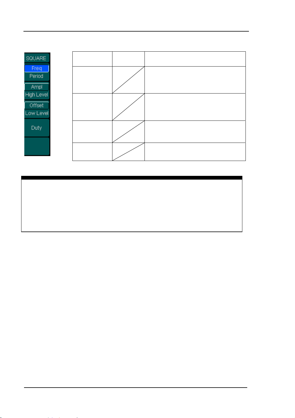
Figure 2-7 Table 2-2 Square Signal Operation Menu
Function Settings
Menu
Explanation
Setting the signal’s frequency or
Freq
Period
period; the current parameter will
switch at a second press.
Setting the signal’s Amplitude or
Ampl
High Level
High Level; the current parameter
will switch at a second press.
Offset
Low Level
Duty
Setting the signal’s Offset or Low
Level; the current parameter will
switch at a second press
Setting the Duty Cycle for Square
Waveform
Term Explanation:
Duty Cycle: The percentage that the High Level takes up the whole Period.
Please Note : for the Frequency Duty Cycle Value
Below 25MHz: 20% to 80%
From 25MHz to 50MHz (included): 40% to 60%
Higher than 50MHz: 50%
2-8 © Copyright RIGOL Technologies, Inc. 2007.
User Guide for DG3000 Series
Page 37
RIGOL
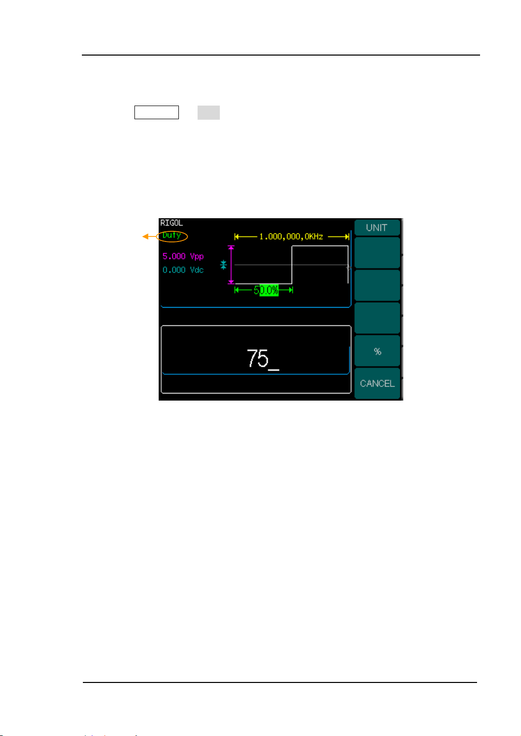
To Set the Duty Cycle
(1). Press Square Æ Duty,to set the Duty Cycle.
The Duty Cycle shown on the screen when the instrument is powered is the default
value or the set value beforehand. When changing the function, if the current value is
valid for the new waveform, it will be used sequentially.
(2). Input the desired Duty Cycle
Use the keypad or the knob to input the desired value, choose the unit, and press the
corresponding button. The Generator will change the waveform immediately.
Current
Parameter:
Duty Cycle
Figure 2-8
Setting the Duty Cycle
© Copyright RIGOL Technologies, Inc. 2007. 2-9
User Guide for DG3000 Series
Page 38

RIGOL
To Set Ramp Signals
Press Ramp button to call the Ramp operation. The output Ramp waveform
parameters are set using the Ramp operation menu.
The parameters for Ramp waveforms are: Frequency/ Period, Amplitude/ High Level,
Offset/ Low Level and Symmetry. See Figure 2-9. The parameter value in the
waveform display window is the same as that of in the parameter display window and
the Symmetry value is edited directly in the waveform display window. In the soft key
menu, select Symmetry, and the corresponding value in the waveform display window
will be displayed in darken color. Users can then edit its value.
Symmetry
Figure 2-9
Ramp Signal Parameter Setting Interface
2-10 © Copyright RIGOL Technologies, Inc. 2007.
User Guide for DG3000 Series
Page 39

Figure 2-10 Table 2-3 Ramp Signal Operation Menu
RIGOL
Function Settings
Menu
Freq
Period
Ampl
High Level
Offset
Low Level
Term Explanation:
Symmetry: The percentage that the Rising Period takes up the whole Period.
Input Range: 0~100%
Symmetry
Setting the signal’s frequency or
period; the current parameter will
switch at a second press.
Setting the signal’s Amplitude or
High Level; the current parameter
will switch at a second press.
Setting the signal’s Offset or Low
Level; the current parameter will
switch at a second press
Setting the Symmetry for Ramp
Waveform
Explanation
© Copyright RIGOL Technologies, Inc. 2007. 2-11
User Guide for DG3000 Series
Page 40

RIGOL
To Set the Symmetry
(1). Press Ramp Æ Symmetry,to set the Symmetry.
The Symmetry shown on the screen when the instrument is powered is the default
value or the set value beforehand. When changing the function, if the current value is
valid for the new waveform, it will be used sequentially.
(2). Input the desired Symmetry
Use the keypad or the knob to input the desired value, choose the unit, and press the
corresponding button. The Generator will change the waveform immediately.
Current
Parameter:
Symmetry
Figure 2-11
Setting the Symmetry
2-12 © Copyright RIGOL Technologies, Inc. 2007.
User Guide for DG3000 Series
Page 41

RIGOL
To Set Pulse Signals
Press Pulse button to call the Pulse operation. The output Pulse waveform
parameters are set using the Pulse operation menu.
The parameters for Pulse waveforms are: Frequency/ Period, Amplitude/ High Level,
Offset/ Low Level, Pulse Width and Edge Time. See Figure 2-12. The parameter value
in the waveform display window is the same as that of in the parameter display
window and the Pulse Width and the Edge Time values are edited directly in the
waveform display window. In the soft key menu, select Pulse Width, and the
corresponding value in the waveform display window will be displayed in darken color.
Users can then edit its value.
Pulse Width
Edge Time
Figure 2-12
Pulse Signal Parameter Setting Interface
© Copyright RIGOL Technologies, Inc. 2007. 2-13
User Guide for DG3000 Series
Page 42

RIGOL
Figure 2-13 Table 2-4 Pulse Signal Operation Menu
Function
Menu
Settings
Explanation
Setting the signal’s frequency or period;
Freq
Period
the current parameter will switch at a
second press.
Ampl
High Level
Setting the signal’s Amplitude or High
Level; the current parameter will switch at
a second press.
Offset
Low Level
Pulse Width
Setting the signal’s Offset or Low Level;
the current parameter will switch at a
second press
Setting the Pulse Width for Pulse
Waveform
Edge Time Setting the Edge Time for Pulse Waveform
Term Explanation:
Pulse Width: The time span between thresholds of 50% of the rising edge
amplitude to the next 50% of the falling edge amplitude.
Edge Time:
The time span between the thresholds of the 10% to 90% of the rising edge
amplitude is called Rising Time.
The time span between the thresholds of the 90% to 10% of the falling edge
amplitude is called Falling Time.
The Rising Time and the Falling Time together called Edge Time.
2-14 © Copyright RIGOL Technologies, Inc. 2007.
User Guide for DG3000 Series
Page 43

RIGOL
To Set the Pulse Width
(1). Press Pulse Æ Pulse Width,to set the Pulse Width.
The Pulse Width shown on the screen when the instrument is powered is the default
value or the set value beforehand. When changing the function, if the current value is
valid for the new waveform, it will be used sequentially.
(2). Input the desired Pulse Width
Use the keypad or the knob to input the desired value, choose the unit, and press the
corresponding button. The Generator will change the waveform immediately.
Current
Parameter:
Pulse Width
Figure 2-14
Setting the Pulse Width
© Copyright RIGOL Technologies, Inc. 2007. 2-15
User Guide for DG3000 Series
Page 44

RIGOL
To Set the Edge Time
(1). Press Pulse Æ Edge Time,to set the Edge Time.
The Edge Time shown on the screen when the instrument is powered is the default
value or the set value beforehand. When changing the function, if the current value is
valid for the new waveform, it will be used sequentially.
(2). Input the desired Edge Time
Use the keypad or the knob to input the desired value, choose the unit, and press the
corresponding button. The Generator will change the waveform immediately.
Current
Parameter:
Pulse Edge
Figure 2-15
Setting the Edge Time
Instruction:
The default setting is the same Edge Time for Rising and Falling Edges.
2-16 © Copyright RIGOL Technologies, Inc. 2007.
User Guide for DG3000 Series
Page 45

RIGOL
To Set Noise Signals
Press Noise button to call the Noise operation. The output Noise waveform
parameters are set using the Noise operation menu.
The parameters for Noise waveforms are: Amplitude/ High Level and Offset/ Low
Level. See Figure 2-16. The parameter value in the waveform display window is the
same as that of in the parameter display window. In the soft key menu, select Offset,
and the corresponding value in the waveform display window will be displayed in
darken color. Users can then edit its value. Noise is non-regulated signal which has no
frequency or period.
Figure 2-16
Noise Signal Parameter Setting Interface
© Copyright RIGOL Technologies, Inc. 2007. 2-17
User Guide for DG3000 Series
Page 46

RIGOL
Figure 2-17 Table 2-5 Noise Signal Operation Menu
Function Settings
Menu
Explanation
Setting the signal’s Amplitude or
Ampl
High Level
High Level; the current parameter
will switch at a second press.
Offset
Low Level
Setting the signal’s Offset or Low
Level; the current parameter will
switch at a second press
2-18 © Copyright RIGOL Technologies, Inc. 2007.
User Guide for DG3000 Series
Page 47

RIGOL
To Set Arbitrary Signals
Press Arb button to call the Arb operation. The output Arb waveform parameters are
set using the Arb operation menu.
The Arb signal consists of two types: the system built-in waveform and the
user-definable waveform. The parameters for Arb waveforms are: Frequency/ Period,
Amplitude/ High Level and Offset/ Low Level. See Figure 2-18. The parameter value
in the waveform display window is the same with that of in the parameter display
window. In the soft key menu, select Amplitude, and the corresponding value in the
waveform display window will be displayed in darken color. Users can then edit its
value.
Figure 2-18
Arbitrary Signal Parameter Setting Interface
© Copyright RIGOL Technologies, Inc. 2007. 2-19
User Guide for DG3000 Series
Page 48

RIGOL
Figure 2-19 Table 2-6 Arbitrary Signal Operation Menu
Function Settings
Menu
Explanation
Setting the signal’s frequency or
Freq
Period
period; the current parameter will
switch at a second press.
Setting the signal’s Amplitude or
Ampl
High Level
High Level; the current parameter
will switch at a second press.
Offset
Low Level
Sel Wform
Edit Wform
Setting the signal’s Offset or Low
Level; the current parameter will
switch at a second press
Select the built-in Arbitrary Signal
as Output
Create and Edit Arbitrary
Waveform
2-20 © Copyright RIGOL Technologies, Inc. 2007.
User Guide for DG3000 Series
Page 49

RIGOL
To Select the built-in Arbitrary Waveform
There are five built-in Arbitrary Waveforms and user-definable Arbitrary Waveforms
inside the Generator. To select one of them, follow the instructions below:
Press Arb Æ Load,to enter the interface shown below.
Figure 2-20 Table 2-7 Selection Menu for Built-in Arbitrary Waveform
Function
Menu
Built-in
Stored
Wform
Volatile
Wform
DELETE
Instructions:
1. When there is no waveform stored in the Non-Volatile Memory, the Stored
Menu and the Delete Menu will hide.
2. When there is no waveform in the Volatile Memory, the Volatile menu will
hide.
Wform
CANCEL
Settings
Select one of the five built-in Arbitrary
Waveforms (See Table 2-8)
Select one of Arbitrary Waveforms
stored in the Non-volatile memory
Select one of Arbitrary Waveforms
stored in the Volatile memory. When a
new waveform is created, the old one
will be erased.
Delete one of the Arbitrary Waveforms
stored in the Non-volatile memory. The
five Built-in Waveforms can not be
deleted.
Cancel the current operation, and return
to the upper menu. (The rest are the
same and will not be covered)
Explanation
© Copyright RIGOL Technologies, Inc. 2007. 2-21
User Guide for DG3000 Series
Page 50

RIGOL
1. To Select the Built-in Waveform
Press Arb Æ Sel Wform Æ Built-In,and enter the following interface.
Figure 2-21(1) Table 2-8(1) The Built-in Arbitrary Waveforms Menu
Function
Menu
ExpRise
ExpFall
NegRamp
Sinc
1/2
Settings
Explanation
Select the built-in Exponential Rise
Waveform
Select the built-in Exponential Fall
Waveform
Select the built-in Negative Ramp
Waveform
Select the built-in Sinc Waveform.
Sinc=Sin(x)/x
Enter next page ( the rest is the
same)
Figure 2-21(2) Table 2-8(2) The Built-in Arbitrary Waveforms Menu
Function Settings
Menu
2/2
Return previous page (the rest is the
same)
Explanation
Cardiac Select the built-in Cardiac Waveform
2-22 © Copyright RIGOL Technologies, Inc. 2007.
User Guide for DG3000 Series
Page 51

RIGOL
2. To Select the Stored Waveform
Press Arb Æ Sel Wform Æ Stored Wform ,and enter the following interface.
Figure 2-22(1) Table 2-9(1) The Stored Arbitrary Waveform Menu
Function
Menu
Settings
Explanation
Select the Arb Waveform stored in the
ARB Mem1
non-Volatile Memory. The location is:
C:\ARB1:ARB_1
Select the Arb Waveform stored in the
ARB Mem 2
non-Volatile Memory. The location is:
C:\ARB2:ARB_2
Select the Arb Waveform stored in the
non-Volatile Memory. The location is:
C:\ARB3:ARB_3
ARB Mem 3
Select the Arb Waveform stored in the
ARB Mem 4
non-Volatile Memory. The location is:
C:\ARB4:ARB_4
Figure 2-22(2) Table 2-9(2) The Stored Arbitrary Waveform Menu
Function Settings
Menu
Explanation
Select Arb Open the selected waveform
Instructions:
When there is no waveform stored in the Arb Mem1 、 Arb Mem2 、 Arb Mem3
and Arb Mem4, this menu will hide (The rest is the same and will not be
covered )
© Copyright RIGOL Technologies, Inc. 2007. 2-23
User Guide for DG3000 Series
Page 52

RIGOL
3. To Remove the Waveform
Press Arb Æ Sel Wform Æ DELETE Wform , and enter the following
interface.
Figure 2-23(1) Table 2-10(1) The Stored Arbitrary Waveform Menu
Function Settings
Menu
Explanation
Select the Arb Waveform stored in the
ARB Mem1
non-Volatile Memory. The location is:
C:\ARB1:ARB_1
Select the Arb Waveform stored in the
ARB Mem 2
non-Volatile Memory. The location is:
C:\ARB2:ARB_2
Select the Arb Waveform stored in the
non-Volatile Memory. The location is:
C:\ARB3:ARB_3
ARB Mem 3
Select the Arb Waveform stored in the
ARB Mem 4
non-Volatile Memory. The location is:
C:\ARB4:ARB_4
Figure 2-23(2) Table 2-10(2) The Stored Arbitrary Waveform Menu
Function Settings
Menu
Explanation
Delete Arb Delete the selected waveform
2-24 © Copyright RIGOL Technologies, Inc. 2007.
User Guide for DG3000 Series
Page 53

RIGOL
To Edit the Arbitrary Waveform
The Generator allows users to edit Arbitrary Waveforms, which can create any new
waveform by initializing points. The procedure is as follows:
Press Arb Æ EditWform, to enter the interface shown below.
Figure 2-24 Table 2-11 Waveform Edition Operation Menu
Function
Menu
Create
New
Edit
Stored
Edit
Volatile
DELETE
Wform
Settings
Create a new waveform, and erase
the waveform in the Volatile memory.
Edit the waveform stored in the
non-Volatile memory
Edit the waveform stored in the
Volatile memory
Delete one of the Arbitrary
Waveforms stored in the Non-volatile
memory. The five Built-in Waveforms
can not be deleted.
Explanation
Instructions:
1. When there is no waveform stored in the Non-Volatile Memory, the Edit Stored
Menu and the DELETE Wform Menu will hide.
2. When there is no waveform in the Volatile Memory, the Edit Volatile menu
hide
© Copyright RIGOL Technologies, Inc. 2007. 2-25
User Guide for DG3000 Series
Page 54

RIGOL
1. To Create a New Waveform
Press Arb Æ EditWform Æ Create New ,to set the overall parameter for the
waveform. Interface is shown in Figure 2-25 and menu in Table 2-12.
High Level
Low Level
Period
Initial Points number
Interpolation On
Figure 2-25
Interface for setting the new waveform parameter
Figure 2-26(1) Table 2-12(1) Setting the parameter for the new waveform
Function
Menu
Cycle
Period
HighV Limit
Settings
Explanation
Setting the Cycle Period for the
Waveform
Setting the Level High Limit for
the Waveform
LowV Limit
Int# Points
Setting the Level Low Limit for
the Waveform
Set the number of initial points
when Initializing the waveform
2-26 © Copyright RIGOL Technologies, Inc. 2007.
User Guide for DG3000 Series
Page 55

RIGOL
Figure 2-26(2) Table 2-12(2) Setting the parameter for the new waveform
Function Settings
Menu
Explanation
Activate the linear Interpolation
Interp
On
Off Deactivate the linear Interpolation
between the defined points
between the defined points
Edit Points Turn on the Waveform Editor
To Set the Point Number
Press Int #Points, to set the number of the initializing points
When a new waveform is created, the waveform editor will firstly create a waveform
with two points. The Waveform Editor connects the last point to the Voltage Level of
point #1 automatically to create a continuous waveform. A waveform with at most
512X1024 points can be created.
In the default setting, point #1 is Level High, fixed on 0 second, while point #2 is
Level Low and on the half of the set Cycle period.
To Set the Interpolation
Press Interp.On , if you choose Interpolation On , and the points will be connected
with beelines; otherwise, the voltages between two consecutive points will not
change, and waveform looks like a step-up one.
© Copyright RIGOL Technologies, Inc. 2007. 2-27
User Guide for DG3000 Series
Page 56

RIGOL
To Edit the Waveform Points
Press Arb Æ Edit Wform Æ Create New Æ Edit Points, The waveform can
be defined by setting the time and voltage for each point using this function. The
menu is as follows:
Figure 2-27(1) Table 2-13(1) Waveform Parameter Edition Menu
Function
Menu
Settings
Explanation
Point# Select the point to be edited
Voltage
Set Voltage for the Selected point
Time Set time for the Selected point
Insert a new point between the
Insert
defined points. Use the “Time” and
“Voltage” to define the new point.
Figure 2-27(2) Table 2-13(2) Waveform Parameter Edition Menu
Function Settings
Menu
Remove
Remove the current point
Explanation
Save the created waveform to the
Stored in
Non-Vol
non-Volatile Memory. Resort to
Table 2-14for a detailed Storage
Catalogue
Finish the current operation and
Done
return to the first level menu. (The
rest is the same and will not be
covered)
Instruction:
The time for the last definable point should be less than the cycle period in the
waveform.
2-28 © Copyright RIGOL Technologies, Inc. 2007.
User Guide for DG3000 Series
Page 57

RIGOL
Save the Waveform to the Non-Volatile Memory
Press Arb Æ Edit Wform Æ Create New Æ Edit Points Æ Store in
Non-Vol ,to enter the following interface.
Figure 2-28(1) choose the location
Figure 2-28(2) input the name
© Copyright RIGOL Technologies, Inc. 2007. 2-29
User Guide for DG3000 Series
Page 58

RIGOL
Table 2-14 Save New Waveform Menu
Function Settings
Menu
Explanation
Store the waveform to ARB1 location
File ARB1
File
ARB 2
File
File
ARB 4
and name the file. Press Finish/Done
to finish the operation.
Store the waveform to ARB2 location
and name the file. Press Finish/Done
to finish the operation.
Store the waveform to ARB3 location
ARB 3
and name the file. Press Finish/Done
to finish the operation.
Store the waveform to ARB4 location
and name the file. Press Finish/Done
to finish the operation.
Instruction
To save the Arbitrary Waveform:
In the Non-volatile Memory, each waveform storage place saves only one
waveform. If a new one is stored, the old one will be erased.
For a waveform containing points less than128K, one place will be used.
For a waveform containing points from128K to 256K, two sequential places
will be used.
For a waveform containing points from256K to 512K, All the 4 places will be
used.
2-30 © Copyright RIGOL Technologies, Inc. 2007.
User Guide for DG3000 Series
Page 59

RIGOL
2. To Edit the Stored Waveform
Press Arb Æ Edit Wform Æ Edit Stored, to enter the following interface.
Figure 2-29(1) Table 2-15(1) Edit Stored Waveform Menu
Function
Menu
Settings
Explanation
Select the Arb Waveform stored in the
ARB
Mem1
non-Volatile Memory. The default
location is: C:\ARB1:ARB_1
ARB Mem
2
ARB Mem 3
ARB Mem
4
Select the Arb Waveform stored in the
non-Volatile Memory. The default
location is: C:\ARB2:ARB_2
Select the Arb Waveform stored in the
non-Volatile Memory. The default
location is: C:\ARB3:ARB_3
Select the Arb Waveform stored in the
non-Volatile Memory. The default
location is: C:\ARB4:ARB_4
Figure 2-29(2) Table 2-15(2) Edit Stored Waveform Menu
Function Settings
Menu
Explanation
Edit Arb Edit the selected waveform
3. To Delete a Waveform
Press Arb Æ Edit Wform Æ DELETE Wform, to delete a waveform.
© Copyright RIGOL Technologies, Inc. 2007. 2-31
User Guide for DG3000 Series
Page 60

RIGOL
p
To Generate the Modulated Waveform
Use the Mod button to generate modulated waveform. DG3000 Series can generate
AM, FM, FSK, PM and PWM modulated waveforms. Modulating parameters vary by
the types of the modulation. In AM, users can set the Source (Internal/ External),
depth, Modulating Frequency, Modulating Waveform and Carrier Waveform; in FM,
users can set the Source (Internal/ External), Frequency Deviation, Modulating
Waveform and Carrier Waveform; in FSK, users can set the Source (Internal/
External), Frequency Range, Internal Rate, Modulating Waveform and Carrier
Waveform; while in PM, users can set the Source (Internal/ External), Phase
Deviation, Modulating Frequency, Modulating Waveform and Carrier Waveform, etc.
We will cover how to set these parameters in details by the types of the Modulation.
Modulating
Depth
Type
Sha
e
Source
Carrier
Frequency
waveform
Carrier
Waveform
Carrier
Amplitude
Carrier Offset
Figure 2-30
Modulated Waveform Parameter Interface
2-32 © Copyright RIGOL Technologies, Inc. 2007.
User Guide for DG3000 Series
Page 61

RIGOL
AM
The modulated waveform consists of two parts: the Carrier Waveform and the
Modulating Waveform. In AM, the Amplitude of the Carrier Waveform varies with the
instantaneous voltage of the modulating waveform. The Parameters for the AM are in
Table 2-16.
Press Mod Æ Type Æ AM, to enter the following interface.
Figure 2-31 Table 2-16 Setting the AM parameters
Function
Menu
AM Freq
AM Depth Set the amplitude range
Type AM Amplitude Modulation
Shape
Source
Settings
Set the modulating waveform
frequency. Frequency Range: 2mHZ~
20kHz( Internal Source Only ).
Sine
Square
Triangle
UpRampD
nRampNo
ise
Arb
Internal The Source is Internal
External
Choose the modulating Waveform. To
change the Carrier Waveform
parameter, press Sine , Square etc.
The Source is External. Use the
[Modulation In] connector in the Rear
panel.
Explanation
© Copyright RIGOL Technologies, Inc. 2007. 2-33
User Guide for DG3000 Series
Page 62

RIGOL
Term Explanation
Modulation Depth
The Amplitude Range (also called ‘Percentage Modulation’). Modulation Depth
varies from 1% to 120%.
In the 0% Modulation, the output amplitude is the half of the set one.
In the 100% Modulation,the output amplitude is the same with the set one.
When the modulation is greater than 100%, the instrument output no greater
than 10 Vpp. For an external source, the depth of AM is controlled by the
voltage level of the connector connected to the [Modulation In]. +5V
corresponds to the currently set depth.
2-34 © Copyright RIGOL Technologies, Inc. 2007.
User Guide for DG3000 Series
Page 63

RIGOL
FM
The modulated waveform consists of two parts: the Carrier Waveform and the
Modulating Waveform. In FM, the Frequency of the Carrier Waveform varies with the
instantaneous voltage of the modulating waveform. The Parameters for the FM are as
shown in Figure 2-32.
Modulating
Frequency
Deviation
Frequency
Figure 2-32
FM Waveform Parameter Setting Interface
Press Mod Æ Type Æ FM, to enter the following interface.
Figure 2-33 Table 2-17 Setting the FM parameters
Function
Menu
Settings
Explanation
Set the modulating waveform
FM Freq
frequency. Frequency Range: 2mHZ~
20kHz(Internal Source Only).
Set the Frequency Deviation between
FM Dev
the Modulating Waveform and the
Carrier Waveform
Type FM Frequency Modulation
© Copyright RIGOL Technologies, Inc. 2007. 2-35
User Guide for DG3000 Series
Page 64

RIGOL
Term Explanation
Frequency Deviation
The Deviation should be equal to or less than the Carrier Waveform Frequency.
The Sum of the Deviation and the Carrier Frequency should be equal to or less
than maximum frequency of the selected function plus 100 kHz.
For an External Source, the Deviation is controlled by the ±5V voltage Level of
the Connector connected to the [Modulation In]. +5V corresponds to the
selected Deviation and -5V to the negative selected Deviation.
2-36 © Copyright RIGOL Technologies, Inc. 2007.
User Guide for DG3000 Series
Page 65

RIGOL
FSK
The FSK Modulation is a modulation method, the output frequency of which switches
between two the pre-set frequencies (Carrier Waveform Frequency and the Hop
Frequency). The Frequency for the Output Frequency to switch from the carrier
waveform frequency to and from the Hop frequency is called the FSK rate. The
frequency by which the output frequency switch from each other is determined by the
Internal Frequency generator or the Signal Voltage Level offered by the Trig In
connector in the rear panel:
FSK Rate
Figure 2-34
FSK Waveform Parameter Setting Interface
Hop
Frequency
© Copyright RIGOL Technologies, Inc. 2007. 2-37
User Guide for DG3000 Series
Page 66

RIGOL
Press Mod Æ Type Æ FSK, to enter the following interface.
Figure 2-35 Table 2-18 Set FSK Parameters
Function Settings
Menu
Explanation
Set the frequency at which the output
frequency shifts between the carrier
FSK Rate
frequency and the Hop frequency
(Internal Modulation Only): 2mHZ~1
MHz
Type FSK Frequency Shift Keying Modulation
Hop Freq Set the Hop Frequency
2-38 © Copyright RIGOL Technologies, Inc. 2007.
User Guide for DG3000 Series
Page 67

RIGOL
PM
The modulated waveform consists of two parts: the Carrier Waveform and the
Modulating Waveform. In PM, the Phase of the Carrier Waveform varies with the
instantaneous voltage Level of the modulating waveform. The Parameters for the PM
are as shown in Figure 2-36.
Phase
Deviation
PM Frequency
Figure 2-36
PM Waveform Parameter Setting Interface
Press Mod Æ Type Æ PM, enter the following interface.
Figure 2-37 Table 2-19 Setting the PM parameters
Function Settings
Menu
Explanation
Set the modulating waveform
PM Freq
frequency. Frequency Range: 2mHZ~
20kHz(Internal source Only).
Set the Phase Deviation between the
Phase Dev
Modulating Waveform and the Carrier
Waveform, ranging from 0
Type PM Phase Modulation
o
to 360
o
© Copyright RIGOL Technologies, Inc. 2007. 2-39
User Guide for DG3000 Series
Page 68

RIGOL
PWM
The modulated waveform consists of two parts: the Carrier Waveform and the
Modulating Waveform. In PWM, the width of the Carrier Waveform (Pulse) varies with
the instantaneous voltage of the modulating waveform. The parameters for PWM are
as shown in Figure 2-38.
PWM can only be used for pulse modulation, press Mod, enter the modulation
interface you may discover that the function key PWM is cryptic when you choose the
modulation type, but it will appear when you press Mod in the Pulse interface.
Figure 2-38
PWM Waveform Parameter Setting Interface
Press Pulse—> Mod , enter the following menu.
Figure 2-39 table 2-20 Setting the PWM parameters
Function Setting
Menu
s
Explanation
Set the modulating waveform
FM Freq
frequency. Frequency Range:2mHz ~
20kHz(only for internal source).
Width
Dev
The setting range :0~200us
Internal Choose the internal source.
Source
External
Choose the external source, use the
linker [Modulation In] in the rear panel.
2-40 © Copyright RIGOL Technologies, Inc. 2007.
User Guide for DG3000 Series
Page 69

RIGOL
Note:
The maximum of the (duty deviation)/(width deviation) is the smaller one
in [(pulse duty/width), 1-pulse width].
© Copyright RIGOL Technologies, Inc. 2007. 2-41
User Guide for DG3000 Series
Page 70

RIGOL
To Generate Sweep
In the frequency sweep mode, the function generator “steps” from the start
frequency to the stop frequency at the sweep rate you specify. Sweep can be
generated by Sine, Square, Ramp or Arbitrary Waveforms (Pulse, Noise and DC are
not allowed).
Start Frequency
Stop Frequency
Source
Trigger
Sweep Time
Marker
Type
Figure 2-40
Sweep Waveform Parameter Setting Interface
Press Sweep button to enter the following menu. Set the Waveform parameters by
using the operation menu.
2-42 © Copyright RIGOL Technologies, Inc. 2007.
User Guide for DG3000 Series
Page 71

Figure 2-41 (1) Table 2-21(1) Waveform Sweep Setup
RIGOL
Function Settings
Menu
Explanation
Set the Time Span of the Sweep for
Swp Time
which the Frequency changes from the
Start Frequency to Stop Frequency.
Stop Freq Set the Stop Frequency of the Sweep
Freq Span Set the Frequency Span of the Sweep
Start Freq Set the Start Frequency of the Sweep
Center Freq Set the Center Frequency of the Sweep
Source
Internal
External
Mannal
Choose Internal Source
Choose External Source, use the
[Modulation In] connector in the rear
panel
Choose External Source, set the start
and stop time by hand
© Copyright RIGOL Technologies, Inc. 2007. 2-43
User Guide for DG3000 Series
Page 72

RIGOL
Sweep Frequency Setting
Use Start Freq and Stop Freq or Center Freq and Freq Span to set the range of the
frequency. Press the button again to switch between each other.
z To Sweep upward, set the Start Frequency lower than the Stop Frequency, or set
a positive frequency interval.
z To Sweep downward, set the Start Frequency higher than the Stop Frequency, or
set a negative frequency interval.
Figure 2-41(2) Table 2-21(2) Waveform Sweep parameter setting
Function Settings
Menu
Trig
Marker
Linear
Log
Off
Freq Choose the Marker Frequency
Off Turn Off the Marker Frequency
Signal Triggered at Rise Edge
Signal Triggered at Fall Edge
Turn off Trigger Setting
Set the Sweep with linear spacing
Set the Sweep with logarithmic
spacing
Explanation
2-44 © Copyright RIGOL Technologies, Inc. 2007.
User Guide for DG3000 Series
Page 73

RIGOL
Mark On/Off
Choose the Mark Frequency, and the frequency of the Signal on the [Sync] Connector
will change according to this frequency. The Output of the [Sync] Connector will turn
High at the start of the Sweep. If you close the Mark, the synchronous signal will turn
Low at the center of the Sweep; otherwise, the synchronous signal turns Low when
the frequency reaches the specific mark. The Mark Frequency should be between the
Start Frequency and the Stop Frequency.
If the synchronous signal is disabled, then disable Mark Signal.
© Copyright RIGOL Technologies, Inc. 2007. 2-45
User Guide for DG3000 Series
Page 74

RIGOL
To Generate Burst
Burst Function can generate versatile waveforms in burst, which can last specific
times of waveform cycle(N-Cycle Burst), or when external gated signals( Gated Burst)
is applied, any waveform could be used, But noise can only be used in Gated Burst.
Press Burst button to enter the following interface. Set the Waveform parameters by
using the operation menu.
Burst Period
Start Phase
N Cycle
Source
Trigger Setting
Cycle Period
Delay
Figure 2-42
Burst Waveform Parameter Setting Interface
2-46 © Copyright RIGOL Technologies, Inc. 2007.
User Guide for DG3000 Series
Page 75

Set the N-Cycle Burst
Press Burst Æ N Cycle, to enter the following interface.
Figure 2-43(1) Table 2-22(1) Setting the N-Cycle parameters
RIGOL
Function Settings
Menu
Burst
Period
Start
Phase
N Cycle
Gated
Burst Period
Set the time span between an N-Cycle Burst to the next. If necessary the period will
increase to allow the specific number of cycles in a burst.
Burst Period> Period X Burst Number
Start Phase
Define the Start and the Stop Point in a waveform. The phase varies from -360° to
+360°, and the default setting is 0°. For an Arbitrary Waveform, 0° is the first
waveform point.
N-Cycle/ Gated
N-Cycle has specific number of waveform cycles, and every burst is activated by a
trigger event. Gated burst use external source to control burst as when to be
activated.
Source
Set the Burst Period
Set the Start Phase of the Burst
Internal
External
Manual
Use the N-Cycle Mode
Use the Gated Mode
Choose Internal Source
Choose External Source, use the
[Modulation In] connector in the rear
panel
Choose External Source, set the start and
stop time by hand
Explanation
© Copyright RIGOL Technologies, Inc. 2007. 2-47
User Guide for DG3000 Series
Page 76

RIGOL
Figure 2-43(2) Table 2-22(2) N Cycle Burst Setting
Function Settings
Menu
Trig
Signal Triggered at Rise Edge
Signal Triggered at Fall Edge
Explanation
Off Turn off Trigger S e t t i n g
#Cycle Set the Number of the bursts in a N-Cycle
Infinite
Set the Number of the bursts in a N-Cycle
to be infinite
Delay Set the Delay time before the burst starts
# Cycle
Set the number of Waveform Cycle in an N-Cycle (1 to 500,000 or Infinite).
If you choose Infinite, then a continuous waveform will be generate which will not
shop until a trigger event happens (Trigger button is pressed).
z If needed, Burst Period will increase to cater to the specific number of cycles.
z For a frequency greater than 25M Hz, only a bust with infinite cycles is allowed.
z For an infinite-cycle Burst, External or Manual Trigger is needed to activate burst.
Delay
Set the Time Delay between the Trigger Input and the Start of the N-Cycle Burst. The
minimum delay is a function of the specific burst period, and should always be
greater than 0.
2-48 © Copyright RIGOL Technologies, Inc. 2007.
User Guide for DG3000 Series
Page 77

Set the Gated Burst
Press Burst Æ Gated, to enter the following interface.
Figure 2-44 Table 2-23 Setting the Gated parameters
RIGOL
Function Settings
Menu
Start
Phase
N Cycle
Gated
Polarity
Set the Gated Mode
Positive
Negative
Set the Start Phase for the Gated
Signal
Set the Polarity for the Gated Signal
Explanation
© Copyright RIGOL Technologies, Inc. 2007. 2-49
User Guide for DG3000 Series
Page 78

RIGOL
To Store and Recall
Press Store/Recall Button to enter the following interface. You can save or recall the
State or Data Documentation inside the Generator. The status file and data file on the
U Disk are also allowed to rebuild or delete. File names can either be Chinese or
English.
Figure 2-45
Save and Read Interface
Figure 2-46(1) Table 2-24(1) Save and Recall Menu
Function
Menu
File Type
Browser Directory
Save
2-50 © Copyright RIGOL Technologies, Inc. 2007.
Recall
Settings
State
Data Arbitrary Waveform file
All File
Path
File
User Guide for DG3000 Series
The Setting of the Generator
All kinds of files
Shift between the Path,
Directory and file
Save the waveform to the
appointed place( See Table
2-25
Recall the waveform or
Setting information in the
specific position in the
memory.
Explanation
Page 79

Figure 2-46(2) Table 2-24(2) Save and Recall Menu
RIGOL
Function Settings
Menu
Explanation
Delete Delete the selected file
About the browser
The directory selection shift is done by the direction keys. In the directory mode,
pressing the right key will open the lower directory while the left key will fold the
directory. Up and Down key are used to shift between the directories; in the Path
mode, right key stands for the lower directory, left key upper, up key route, and down
key the lowest or the stroll bar between the files.
© Copyright RIGOL Technologies, Inc. 2007. 2-51
User Guide for DG3000 Series
Page 80

RIGOL
To Save the Instrument State
Users are allowed to store the instrument state in any of the 4 Non-Volatile Memories.
The state storage will “memorize” the selected function (including the Arbitrary
Waveform), Frequency, Amplitude, DC Offset, Duty Cycle, Symmetry, and other
modulation parameter used.
To Save the Instrument State, the procedures are as follows:
(1). Choose the file Type to store
Press Store/Recall Æ TypeÆ State, and choose State as the storage type.
(2). Choose the location of the file.
There are four positions in the Local(C :) STATE1, STATE2, STATE3 and STATE4,
choose anyone of them by rotating the knob.
(3). Name the file and Save it
Press Save button, enter the desired name. Press End/Store to finish.
2-52 © Copyright RIGOL Technologies, Inc. 2007.
User Guide for DG3000 Series
Page 81

RIGOL
To Save Data
Users are allowed to store data document on any of the 4 Non-Volatile Memories. If
the place is already occupied, new document will cover the old one. The procedure
for data storage is as follows:
(1). Choose the file Type to store
Press Store/Recall ÆType Æ data, and choose data as the storage type.
(2). Choose the location of the file.
There are four positions in the Local(C :) ARB1, ARB2, ARB3 and ARB4, choose
anyone of them by rotating the knob.
(3). Name the file and Save
Press Save button, enter the desired name. Press End/Store to finish.
© Copyright RIGOL Technologies, Inc. 2007. 2-53
User Guide for DG3000 Series
Page 82

RIGOL
The Seamless Interaction of DG3000 and DS1000
Above we have introduced to you the interfaces of DG3000, and mentioned the USB
Host Interface. Below, we will introduce to you how to use this interface to connect
DG3000 and DS1000 to realize the nondestructive data Transmission.
Step one, Connect DG3000 with DS1000, and acquire data.
Step two, Connect the USB Host Interface of DG3000 with the USB Device Interface
of DS1000. View the waveform acquired. The procedures are as follows:
View the Acquired Waveform
Press Store/Recall Button, to enter the following menu.
Figure 2-47
The operation menu
2-54 © Copyright RIGOL Technologies, Inc. 2007.
User Guide for DG3000 Series
Page 83

RIGOL
Press BrowserÆ Directory, use the knob to select DS1102C and make it be
displayed in inverse color.
Figure 2-48
Choose the directory
N
O
:
Press Browser Æ File, use the direction key to choose CC
1
H
1
H
C
1
H
and make it be
N
O
:
N
O
:
displayed in inverse color (choose the channel that you want to recall the
information).
Figure 2-49
Choose the channel
When the preparation is done, the following steps will help you read the information
DS1000 acquired.
© Copyright RIGOL Technologies, Inc. 2007. 2-55
User Guide for DG3000 Series
Page 84

RIGOL
Press Recall and DG3000 will recall the waveform data acquired by DS1000 into the
Volatile Memory.
Note: when recalling, DG3000 will recall once and write once, so there will be 2
processing bar. If there is only one shown, it means that the recall operation is
unsuccessful.
To generate the waveform acquired
Press Arb Æ Sel Wform Æ Volatile Wform, to load the waveform just recalled.
Figure 2-50
Load the waveform
Notes:The frequency shown on DG3000 may vary greatly from what you imagine.
This is because that DG3000 consider the 512K points acquired as a period. If you
want to get the real period of the generated waveform, you have to use the frequency
value shown on DG3000 times the number of the real period in this false period.
As shown in the figure below, this is the waveform shown on another DS1000 using
the above operation. Please note that the frequency shown on this instrument is the
same as the precious one.
2-56 © Copyright RIGOL Technologies, Inc. 2007.
User Guide for DG3000 Series
Page 85

Figure 2-51
The Reappearance waveform
RIGOL
© Copyright RIGOL Technologies, Inc. 2007. 2-57
User Guide for DG3000 Series
Page 86

RIGOL
TO save the data in the Volatile memory into the
Non-Volatile Memory
The information in the Volatile Memory will disappear once the instrument is powered
off. To save the valuable information, save the information to the Non-Volatile
Memory.
First edit the Arbitrary Waveform in the Arb function and press Arb Æ Edit Wform ,
Figure 2-52
Edit the waveform
Choose Edit Volatile Æ and edit the Points, then enter the
Figure 2-53 Figure 2-54(1)
2-58 © Copyright RIGOL Technologies, Inc. 2007.
User Guide for DG3000 Series
Page 87

Figure 2-54(2)
2/2 page and choose Store in Non-Volatile.
Press Store/Recall, choose the location, to finish the operation.
RIGOL
Figure 2-55
Choose the location
© Copyright RIGOL Technologies, Inc. 2007. 2-59
User Guide for DG3000 Series
Page 88

RIGOL
To Use USB storage
As is shown in figure 2-56, the storage location is divided into: The internal Storage
Local(C :) and the U Disk storage U Disk (A :). At the left side of the front panel, there
is a USB interface. When a USB storage is connected, the storage menu will show
“Mobile Disk (A:)”. Otherwise, the default location is the internal location Local(C :).
Figure 2-56
To use the USB Storage
(1). Install the Mobile Disk
Insert the Mobile Disk into the USB interface on the front panel, and the screen
will show “Detect a Mobile Disk”, and storage menu will show “Mobile Disk ( A:)”
(2). Choose the Mobile Disk
Press Browser ÆDirectory, move the cursor with the up or down direction key
to select “Mobile Disk ( A:)”. Press the right key to open the lower directory, use
the up and down direction key to choose the file” DG3000”. Use the right key to
open the lower directory, and up and down key to select the file “Workspace”.
Input the file name and save.
(3). Remove the Mobile Disk
Remove the Mobile Disk from the Interface. The system will inform you “The
Mobile Disk is removed”, and the “Mobile Disk (A:)” in the storage menu will
disappear.
Note: Mobile Disk can only be U Disk; portable hard disk is not supported.
2-60 © Copyright RIGOL Technologies, Inc. 2007.
User Guide for DG3000 Series
Page 89

RIGOL
To Save a File
Press Store/Recall ÆStore, to enter the following interface. Enter the desired file
name in the “File Name” frame. In the middle of the figure below is the input keypad,
used to edit the file name. Use the up and down direction keys and knob to select the
desired character; use the left and right direction keys to edit the input file name.
Figure 2-57
File Storage Interface
Figure 2-58 Table 2-25 File Storage Menu
Function Settings
Menu
Input
Type
SELECT Select the current character
Delete
End/
Store
En
Chn(s)
English Input
Chinese Input
Delete the current character
Store the file with the current
name
Explanation
© Copyright RIGOL Technologies, Inc. 2007. 2-61
User Guide for DG3000 Series
Page 90

RIGOL
1. English Input
The English Input Interface is as shown in Figure 2-59, to save a file named “NewFile”,
follow the steps below:
File Name
Input Window
Key Pad
Figure 2-59
English Input Interface
(1). Press Input Type Æ En, to enter the English Interface.
(2). Input the file name” NewFile”.
Use the Knob to adjust the cursor’s horizontal position and the up and down key
to adjust the vertical position. Select the Character “N” and press Select. Repeat
this until you have inputted “NEWFile” . Press the +/- button on the number
Keypad to shift into the Capitalized Input mode
(3). Edit the File Name
When you have entered a wrong character, move the cursor to the wrong
character to be deleted and press Delete to remove it. Reenter the file name.
(4). Press End/Store, to finish and save the file.
2-62 © Copyright RIGOL Technologies, Inc. 2007.
User Guide for DG3000 Series
Page 91

RIGOL
d
2. Chinese Input
The Chinese Input Interface is as shown in figure 2-60. To save a new file named “信
号发生器”, follow the instructions below:
File Name
Input
Window
Page Controller
Input Menu
Key Pa
Figure 2-60
Chinese Input Interface
(1). Press Input Type ÆChn(s), to enter the Chinese Input Interface.
(2). Press the “+/-”button on the Number Keypad, to shift Capitalization, and choose
the input to be Minuscule and enter Chinese.
(3). Input the file name : “信号发发生器”
Use the Knob to adjust the cursor’s horizontal position and the up and down key
to adjust the vertical position. Select the Character “q” and press Select. Repeat
till all the needed characters are selected. In the Input Menu, choose the Chinese
character you need with the help of the page controller and the 1~9 button on
the keypad.
(4). Edit the wrongly input
When a file name is wrong, move the cursor to the character to remove and
press Delete to remove it and reenter the file name.
(5). Press End/Store , to finish and save the file.
© Copyright RIGOL Technologies, Inc. 2007. 2-63
User Guide for DG3000 Series
Page 92

RIGOL
To Set the Utility Function
With the Utility Function, you can set the parameters of the Generator such as: DC
On/Off, Sync On/Off, Output Parameter, Interface Parameter, System Setting and
Testing Parameter. The DC switch offers the options of DC output or Arbitrary
Waveform Output. Sync Switch offers the option to choose the Sync Signal or not.
Output Setting provides the parameter setting for Load/Impedance, Range, Normal/
Inverse and Phase. Interface Setting offers the storage and load of the configure
parameter setting for GPIB (IEEE-488), LAN, RS232 or USB remove Control. The
System Setting provides the setting for Language, Display, Beep, Screen Guard,
Format, Power System Configure and default setting; Test provides the self-testing
and calibration storage.
Press Utility button, to enter the Utility Menu. Its functions are listed below in table 2
-26.
Figure 2-61(1) Table 2-26(1) Utility System Setting
Function
Menu
DC
Sync
Output
Setup
I/O
Setup
Settings
Explanation
On Set the output waveform to be DC
Off Set the output waveform to be Arbitrary.
On
Off
Activate the Sync Signal on the [Sync]
Connector on the front panel.
Deactivate the Sync Signal on the [Sync]
Connector on the front panel.
Set the Output parameter
Set the I/O
2-64 © Copyright RIGOL Technologies, Inc. 2007.
User Guide for DG3000 Series
Page 93

Figure 2-61(2) Table 2-26(2) Utility System Setting
RIGOL
Function
Menu
System
Setup
Test /
Cal
Settings
Explanation
Set the System Configuration
Test and Calibrate the instrument
Instruction
Sync Switch Setting:
When the amplitude is relatively low, disabling Sync Signal can reduce the
distortion in output. The current choice is stored in Non-Volatile Memory.
If the Sync Signal is already disabled, then the Mark Signal in the Sweep Mode
should also be disabled.
© Copyright RIGOL Technologies, Inc. 2007. 2-65
User Guide for DG3000 Series
Page 94

RIGOL
To Set the DC Output
Press Utility Æ DCÆ On, to enter the following interface. Please note that there is a
“DC ON” sign at the top left of the screen.
Offset
DC ON
Figure 2-62
DC Setting Interface
DC Offset
Set the DC Voltage Level.
To Shift into the Arbitrary Waveform Output
(1). Press Utility Æ DC Æ DC Off , to close DC Output and return to Arbitrary
Waveform output.
(2). Press any functional button, and the waveform output setting turns into the
arbitrary waveform output. The DC option is turned off automatically.
2-66 © Copyright RIGOL Technologies, Inc. 2007.
User Guide for DG3000 Series
Page 95

RIGOL
To Set the Sync Output
The Generator provides Sync output through the [Sync] Connector on the Front Panel.
All standard output functions (except DC and Noise) have a corresponding Sync
Signal. For some Sync applications, they can be disabled if users do not want to use
them,
• In the default setting, the Sync Signal should be connected to the [Sync]
Connector (activated). When the Sync Signal is disabled, the output Voltage of
the [Sync] Connector is Level Low.
• In the Inverse Mode, the Waveform that corresponds to the Sync Signal does not
Inverse.
• The Setting of Mark Signal in the Sweep Mode will deactivate the Sync Signal.
Thus, when the Mark Frequency is enabled (Sweep Mode activated), the Sync
Signal Setting will be overlooked.
• For Sine, Square and Pulse Signal, the Sync Signal is a Square Signal with 50%
Duty Cycle. When the output is positive, The Sync Signal is TTL Level High
compared to 0 V Voltage or DC Offset; when the output is negative, The Sync
Signal is TTL Level Low compared to 0 V Voltage or DC Offset.
• For Square Waves, the Sync Signal is a Square Wave with the same Duty Cycle
with the main output Square Wave. When the Output is positive, The Sync Signal
is TTL Level High compared to 0 V Voltage or DC Offset; when the output is
negative, The Sync Signal is TTL Level Low compared to 0 V Voltage or DC
Offset.
• For Arbitrary Waveform, the Sync Signal is a Square Waveform with 50% Duty
Cycle. At the time when the first output waveform point is generated, the Sync
Signal Voltage is TTL Level High.
• For Internal Modulating AM, FM and PM, the Sync Signal reference is the
Modulated Signal (not the Carrier Signal). The Sync Signal is a Square Waveform
with 50% Duty Cycle. In the first half modulation period, the Sync Signal is TTL
Level High. For External Modulation, the Sync Signal reference is the Carrier
Signal (not the Modulated Signal). The Sync Signal is also a Square Waveform
with 50% Duty Cycle
• For FSK, the Sync Signal Reference is the Hop Frequency, and the Sync Signal is
a Square Waveform with 50% Duty Cycle. For the Hop Frequency, at the hopping
point, the Sync Signal is TTL Level High.
• For a Sweep which disables the Mark function, the Sync Signal is a Square
Waveform with 50% Duty Cycle. When the Sweep starts, the Sync Signal is TTL
Level High and turns Low at the Center of the Sweep. The Sync Frequency equals
© Copyright RIGOL Technologies, Inc. 2007. 2-67
User Guide for DG3000 Series
Page 96

RIGOL
the specific Sweep time. For a Sweep that enables the Mark Function, the Sync
Signal is TTL Level High at the beginning of the Sweep and turns Low at the Mark
Frequency.
• For the Burst, when the burst starts, the Sync Signal is Level High. At the specific
point when the Cycle Number ends, the Sync Signal turns Level Low (If the
Waveform has a relative starting phase, then intersections may occur). For an
infinite burst, the Sync Signal is the same with the Sync Signal of the continuous
Signal.
• For the External Gated Burst, the Sync Signal follows the External Gated Signal.
But, please note that this signal will not turn Level Low until the end of the last
period (If the Waveform has a relative starting phase, then intersections may
occur).
2-68 © Copyright RIGOL Technologies, Inc. 2007.
User Guide for DG3000 Series
Page 97

To Set Output Parameter
Press Utility Æ Output Setup, to enter the following interface.
Figure 2-63 Table 2-27 Output Set Menu
RIGOL
Function
Menu
Load
High Z
Range
Normal
Invert
Adjust
Instruction
Hold Range
Select Hold, to disable Auto adjusting. This will eliminate the” Jitter” caused by the
switch of the Attenuator. But, the precision and the resolution (the fidelity of the
original waveform) may be affected.
Phase
Settings
Set the Load connected to the Output
Auto Allow the Instrument to choose the best
Hold Disable the Auto Adjusting
Connector.
Set the Load connected to the Output
Connector to be High_Z.
Amplifier/ Attenuator
Normal Output
Inverse Output
Set the Phase Offset of the Output
Waveform
Explanation
© Copyright RIGOL Technologies, Inc. 2007. 2-69
User Guide for DG3000 Series
Page 98

RIGOL
1. To Set the Output Load
For the [Output] Connector on the Front panel, the Generator has a built-in 50Ω
series impendence. If the actual load does not match the set one, the displayed
amplitude and offset are incorrect. This function is used to match the displayed
voltage with the expected one.
Steps for setting the Load:
(1). Press Utility Æ Output Setup Æ Load, to enter the following interface.
Please note that the Load Parameter shown on the right bottom is the default
setting when the power is on or the pre-set load value. If the current value is
valid for the output, then is current value will be used.
(2). Input the desired Load Value.
Use the Keypad or the Knob to enter the desired value and choose the unit, Ω or
KΩ, press the corresponding button.
Figure 2-64
Set the Output Load
Instruction
DG3000Series has a fixed 50Ω Series Impendence. No matter what Value the set
parameter is, if the real load is different from the set one, the displayed voltage
will not equal the real voltage.
2-70 © Copyright RIGOL Technologies, Inc. 2007.
User Guide for DG3000 Series
Page 99

RIGOL
2. To Set the Invert Waveform
Press Utility Æ Output Setup Æ Invert, to set the Inverse Waveform Output.
When the waveform is Inverse, no offset will change. An inverse waveform will be
displayed in the Graph Mode.
Normal
Figure 2-65
Normal Waveform
Invert
Figure 2-66
Inverse Waveform
© Copyright RIGOL Technologies, Inc. 2007. 2-71
User Guide for DG3000 Series
Page 100

RIGOL
3. To Adjust the Phase
Press Utility Æ Output Setup Æ Adjust Phase, to enter the following interface
Figure 2-67
Set the Phase
Figure 2-68 Table 2-28 Phase Adjust Menu
Function Settings
Menu
Explanation
Phase Ser the Output Phase by degree.
Set 0
Phase
Reset the phase to 0.
2-72 © Copyright RIGOL Technologies, Inc. 2007.
User Guide for DG3000 Series
 Loading...