

Page 1

User’s Guide RIGOL
Publication number UGB02101-1110
Oct 2008
DG2000 Series Function/Arbitrary Waveform Generator
© 2006 RIGOL Technologies, Inc. All Rights Reserved
DG2041A/DG2021A
Page 2

Page 3

RIGOL
z © 2006 RIGOL Technologies, Inc. All Rights Reserved
z RIGOL products are protected by patent law in and outside of P.R. China.
z Information in this publication replaces all previously corresponding material.
z RIGOL Technologies, Inc. reserves the right to modify or change part of or all
the specifications and pricing policies at company’s sole decision.
NOTE: RIGOL is registered trademark of RIGOL Technologies, Inc.
© 2006 RIGOL Technologies, Inc.
User’s Guide for DG2000 Series
I
Page 4

RIGOL
Safety Notices
Review the following safety precautions carefully before operating the instrument to
avoid any personal injury or damage to the instrument or products connected to it.
To avoid the potential hazards, it is necessary to use the instrument in the manner
specified in this user guide.
The instrument should be serviced only by qualified personnel.
Avoid Fire or Personal Injury
Use proper power line. Only the special power line of the products approved by
the State should be used.
Insert or draw properly. Do not insert draw when the probe and the testing lead
are connected with the power.
Ground the instrument. This generator is grounded through the protective terra
conductor of the power cord. To avoid electric shock, the grounding conductor must
be connected to the earth ground. Make sure that the instrument is properly grounded
before connecting the input or output terminals.
Observe All the Ratings of the Terminal. To avoid fire or shock, observe all the
ratings and symbols that marked on the instrument. Read the user guide carefully
before making connections to the instrument.
Do not operate without Covers. Do not operate your generator with covers or
panels removed.
Avoid Circuit or Wire exposed. Do not touch the exposed connections or
components when the power is on.
Do not operate with suspected failures. If you suspect there is damage with this
product, you have it inspected by qualified service personnel authorized by RIGOL
before further operations.
II
User’s Guide for DG2000 Series
© 2006 RIGOL Technologies, Inc.
Page 5

Provide Proper Ventilation.
Do not operate in wet/damp conditions.
Do not operate in an explosive atmosphere.
Keep the product’s surfaces clean and dry.
RIGOL
© 2006 RIGOL Technologies, Inc.
User’s Guide for DG2000 Series
III
Page 6
RIGOL
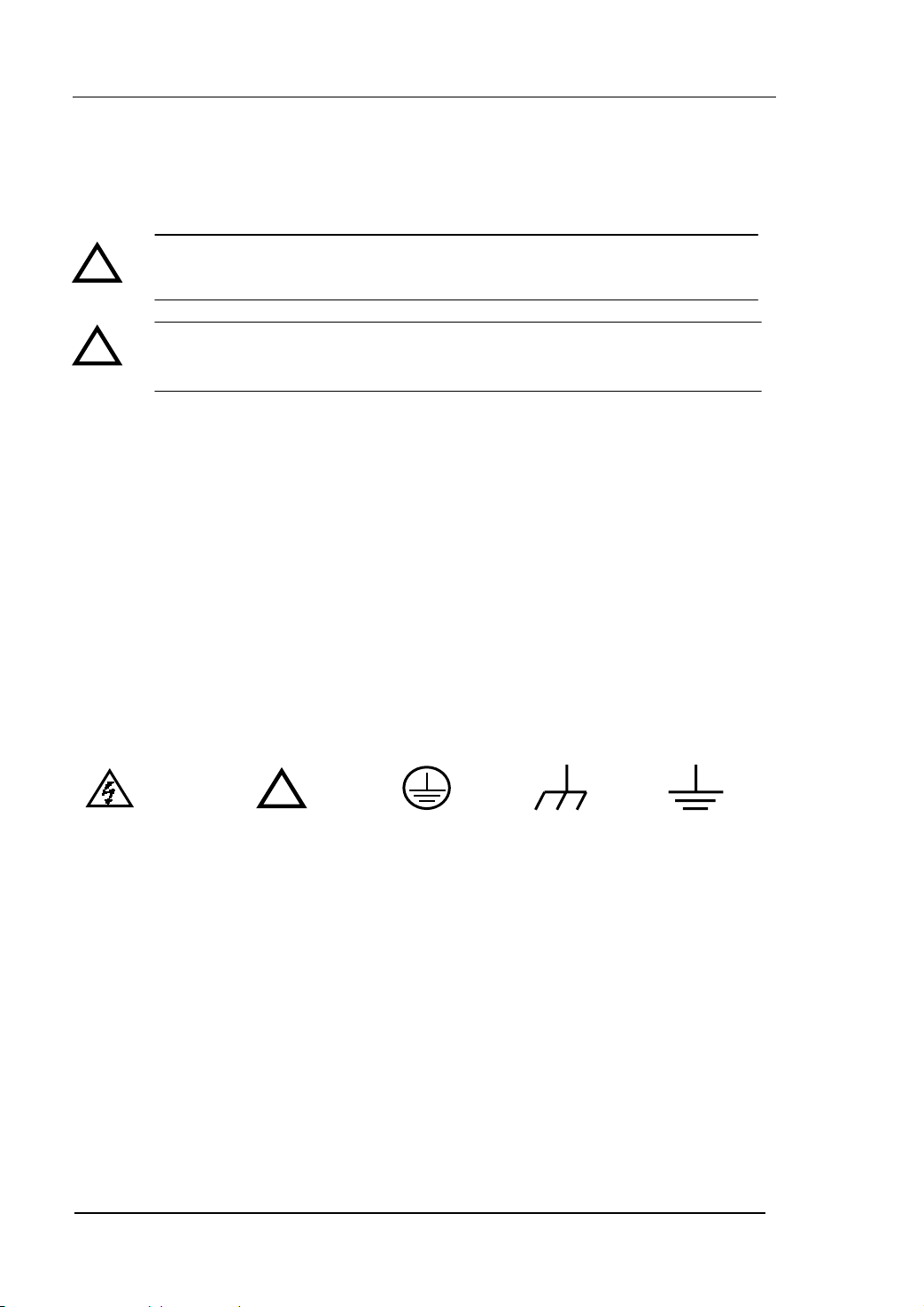
Safety Terms and Symbols
Terms in this guide. These terms may appear in this manual:
!
!
Terms on the product. These terms may appear on the product:
DANGER indicates an injury or hazard that may be immediately happen.
WARNING indicates an injury or hazard that may be not immediately happen.
CAUTION indicates that a potential damage to the instrument or other property
might occur.
Symbols on the product. These symbols may appear on the instrument:
Hazardous
Voltage
WARNING: Warning statements indicate the conditions or practices that
could result in injury or loss of life.
CAUTION: Caution statements indicate the conditions or practices that
could result in damage to this product or other property.
!
Refer to the
Instructions
Protective
Earth
Ground
Chassis
Ground
Earth
Ground
IV
User’s Guide for DG2000 Series
© 2006 RIGOL Technologies, Inc.
Page 7

RIGOL
V
The Introduction of DG2000 Series
This manual covers the following four types of DG2000 Series Function/ Arbitrary
Waveform Generators: DG2041A、DG2021A.
RIGOL DG2000 Series Function/ Arbitrary Waveform Generator adopt the direct
digital synthesizer (DDS) technology, which can provide stable, high-precision, pure
and low distortion sine signal. It can also provide 40MHz square waveform with fast
rising and falling edges. Its combination of excellent system features, easiness in
usage and versatile functions makes this generator a perfect solution for your job now
and in the future.
DG2000 Series Function/ Arbitrary Waveform Generator have clear and simple
Front-Panel. The user-friendly panel layout and instructions, versatile terminals, direct
graph interface, built-in instructions and help system have greatly simplified the
operation process. Thus, users do not have to spend a great deal of time learning and
familiarizing the operation of the generator before they can use it proficiently. The
built-in AM, FM, PM, PWM and FSK modulating functions generate modulated
waveform at ease, without the help of a separate modulating source. The USB I/O,
LAN and GPIB are the standard configuration. Remote instructions meet the SCPI
specification requirements.
From the characteristics and specifications given below, you will understand how
DG2000 can satisfy your measurement requirements.
z 16+2 channels digital output module (optional) together with the analogue
channel can rebuild the most commonly used mixed signal in daily practice.
z DDS technology provides precise, stable and low distortion output signal.
z 10 standard waveforms:
Sine, Square, Ramp, Pulse, Noise, Sinc, Exponential Rise, Exponential Fall,
Cardiac and DC.
z 100MSa/s sampling rate, enable to edit arbitrary waveform with 14-bit, 512K
points.
z Frequency characteristics:
Sine/ Square: 1µHz to 40 MHz
Ramp: 1µHz to 400 kHz
© 2006 RIGOL Technologies, Inc.
User’s Guide for DG2000 Series
Page 8

RIGOL
V
Pulse: 500µHz to 16MHz
White Noise: 20MHz bandwidth (-3dB)
Arbitrary waveform: 1μHz to 12MHz
z Amplitude range: 2mV
pp to 10Vpp (50 Ω)
pp to 20Vpp (High Z)
40mV
z Abundant modulation function, various modulated waveform: AM, FM, PM, PWM
and FSK.
z Linear, logarithm Sweep and Burst mode.
z Abundant I/O: External Modulation Source, External 10 MHz Reference Input,
External trigger source, waveform output, synchronous digital signal output,
Internal 10 MHz Reference output.
z Support USB storage device; store and read waveform configure parameters or
the edited arbitrary waveform with USB devices. System Updating could also be
performed by using USB devices.
z Remote control is realized by using the LAN.
z Standard interface: USB Host & Device, RS-232, GPIB.
z Graph interface which shows the signal setting directly.
z Chinese/English user interface.
z Embedded Chinese/English Help System.
z Support Chinese/English Input.
Note:
All the specifications described in this guide are according to DG2041A, if you need to
know the particular specifications about the other type, please see “Specifications” in
Chapter 5.
I
User’s Guide for DG2000 Series
© 2006 RIGOL Technologies, Inc.
Page 9

RIGOL
V
Content
Safety Notices ...........................................................................................II
The Introduction of DG2000 Series ............................................................. V
Chapter 1 Getting Started ..................................................................... 1-1
General Inspection.................................................................................. 1-2
Handle Adjustment ................................................................................. 1-3
The Front/Rear Panel .............................................................................. 1-4
The DG2000 User Interface ..................................................................... 1-7
To Set a Waveform ................................................................................. 1-8
To Set Modulate/ Sweep/Burst................................................................1-11
To Set Trigger/Output ............................................................................1-13
To Use Digital Input ...............................................................................1-14
To Use Store/Utility/Help Function...........................................................1-15
Chapter 2 Operating Your Generator .................................................... 2-1
The Menu/Graph Mode............................................................................ 2-2
To Set Sine Signals ................................................................................. 2-3
To Set Square Signals ............................................................................. 2-7
To Set Ramp Signals ..............................................................................2-10
To Set Pulse Signals...............................................................................2-12
To Set Noise Signals ..............................................................................2-16
To Set Arbitrary Signals..........................................................................2-17
To Generate the Modulated Waveform ....................................................2-30
To Generate Sweep ...............................................................................2-42
To Generate Burst..................................................................................2-45
To Store and Recall................................................................................2-49
To Set the Utility Function ......................................................................2-58
How to Use the Built-in Help System .......................................................2-81
Chapter 3 Application & Examples ........................................................ 3-1
Example 1: To Generate a Sine Wave....................................................... 3-1
Example 2: To generate a Square Wave ................................................... 3-2
Example 3: To generate a Ramp Wave..................................................... 3-3
Example 4: To generate a Pulse Wave...................................................... 3-4
Example 5: To Generate a Noise Wave..................................................... 3-6
Example 6: To generate Arbitrary Waveform............................................. 3-7
Example 7: To Create an Arbitrary Waveform ........................................... 3-8
© 2006 RIGOL Technologies, Inc
User’s Guide for DG2000 Series
II
Page 10

RIGOL
V
Example 8: To Generate an AM Waveform .............................................. 3-10
Example 9: To Generate an FSK Waveform ............................................. 3-12
Example 10: To generate a PWM Waveform............................................ 3-14
Example 11: To generate a Linear Sweep ............................................... 3-16
Example 12: To generate a Burst Waveform ........................................... 3-18
Chapter 4 Prompt messages & troubleshooting ................................... 4-1
Prompting Messages................................................................................ 4-1
Troubleshooting .................................................................................... 4-17
Chapter 5 Specifications ....................................................................... 5-1
Specifications.......................................................................................... 5-2
General Specifications.............................................................................. 5-7
Chapter 6 Appendix............................................................................... 6-1
Appendix A DG2000 Series Accessories..................................................... 6-1
Appendix B Warranty............................................................................... 6-2
Appendix C General Care and Cleaning ..................................................... 6-3
Appendix D Contact RIGOL ..................................................................... 6-4
Index ........................................................................................................... I
III
User’s Guide for DG2000 Series
© 2006 RIGOL Technologies, Inc
Page 11

Chapter 1 Getting Started
This chapter covers the following topics:
General Inspection
Handle Adjustment
The Front/Rear Panel
The DG2000 User Interface
To S et a Wa ve fo rm
To Set Modulate/ Sweep/Burst
To Set Trigger/Output
RIGOL
To Use Digital Input
To Use Store/Utility/Help Function
© 2006 RIGOL Technologies, Inc
User’s Guide for DG2000 Series
1-1
Page 12

RIGOL
General Inspection
When you get a new DG2000 Series Function/ Arbitrary Waveform Generator, you are
suggested to take the following steps to inspect the instrument.
1. Inspect the shipping container for damage.
If there are damages in the packing or foam, keep them until the whole machine
and the accessories passing the electric and mechanical testing.
2. Check the accessories.
Accessories supplied with the instrument are listed in chapter 6 "Appendix A:
DG2000 Series Accessories".
If the contents are incomplete or damaged, please contract the local selling
representative of RIGOL.
3. Inspect the instrument.
In case any mechanical damage or defect, or if the instrument does not operate
properly or pass performance tests, notify your RIGOL Sales Representative.
If the shipping container is damaged, or the cushioning materials show signs of
stress, notify the carrier of your RIGOL sales office. Keep the shipping materials
for the carrier’s inspection. RIGOL offices will arrange for repair or replacement
at RIGOL’s option without waiting for claim settlement.
1-2
User’s Guide for DG2000 Series
© 2006 RIGOL Technologies, Inc
Page 13
RIGOL
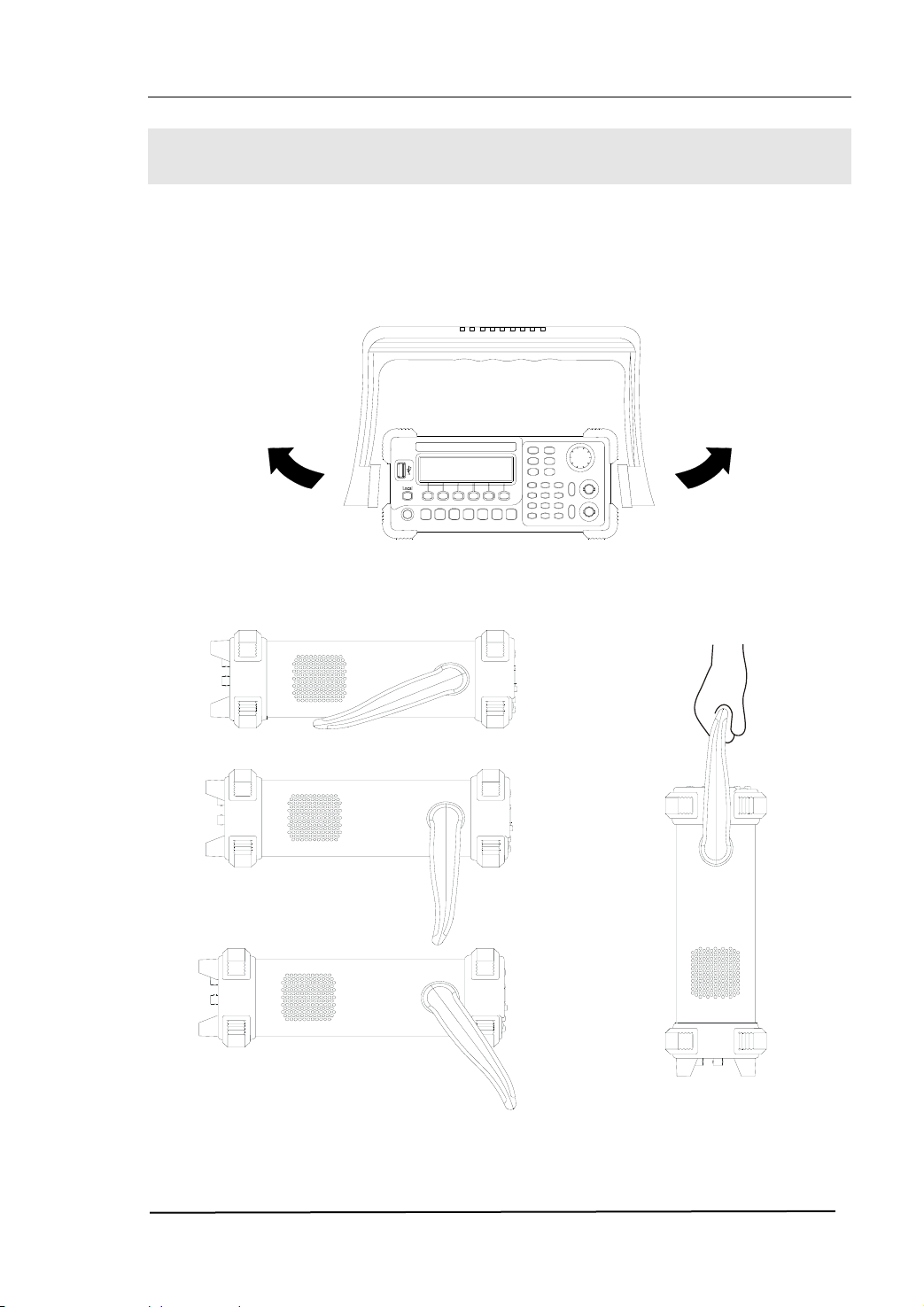
Handle Adjustment
To adjust the handle position of DG2000 Function/ Arbitrary Waveform Generator,
please grip the handle by the sides and pull it outward. Then, make the handle rotate
to the desired position. The operating methods are shown below in figure 1-1 and
figure 1-2.
Figure 1-1 The Method of Adjusting the Handle
Figure 1-2 The Viewing Positions and Carrying Position
© 2006 RIGOL Technologies, Inc
User’s Guide for DG2000 Series
1-3
Page 14
RIGOL
The Front/Rear Panel
When you get a new DG2000 Series Function/ Arbitrary Waveform Generator, first you
need to know how to operate the front/ rear panel correctly. This chapter will make a
brief introduction and description for the operation and functions of the Front/ Rear
Panel.
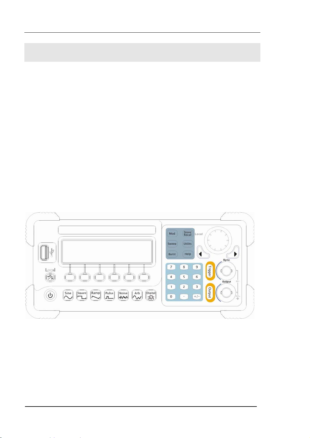
The Front Panel at a Glance
The DG2000 Series Function/ Arbitrary Waveform Generator has clear and simple
front panel. See figure 1-3 and figure 1-4. The Front Panel has a knob, functional keys
and menu buttons. The 6 grey buttons below the screen are menu buttons, with the
help of which, you can choose different options on the current menu. The rests are the
functional keys, with which you can enter different function menus or obtain specific
functional applications directly.
1-4
Figure 1-3 The Front Panel of DG2000 Series
© 2006 RIGOL Technologies, Inc
User’s Guide for DG2000 Series
Page 15
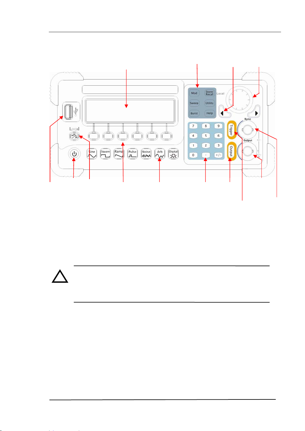
USB Host
Mode/Function
On/Off
Switch
Graph/Text
Mode Key
Menu
Operation
SoftKeys
Waveform
Selection
Keys
Mode/Function
Buttons
Buttons
Number
Keys
Direction
Key
Output
Control
Trigger
Control
Figure 1-4 The Front Panel Operation Instruction of DG2000 Series
NOTE: The [Output] connector and [Sync] connector on the front panel
!
can be only used for the signal output. If they are used for input, it may
make the circuit burned and the instrument in trouble.
RIGOL
Knob
Output
Connector
Sync
Output
© 2006 RIGOL Technologies, Inc
User’s Guide for DG2000 Series
1-5
Page 16
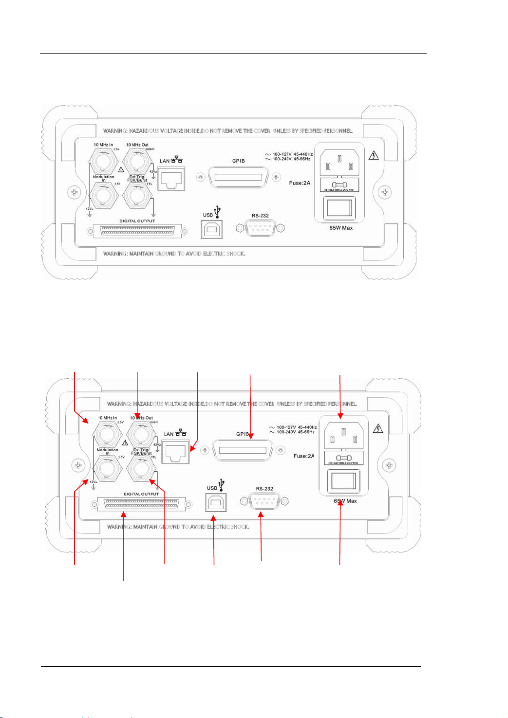
The Rear Panel at a Glance
T
Trig/
Figure 1-5 The Rear Panel of DG2000 Series
10MHz
Reference Input
Term i na l
10MHz
Reference Output
Term i na l
10/100
Ethernet
GPIB
(IEEE 488)
RIGOL
Power Socket
Modulation Input
erminal
Digital
Output
Figure 1-6 The Rear Panel Operation Instruction of DG2000 Series
1-6
External
FSk/Burst
User’s Guide for DG2000 Series
USB Device Main Power
RS-232
Switch
© 2006 RIGOL Technologies, Inc
Page 17
RIGOL
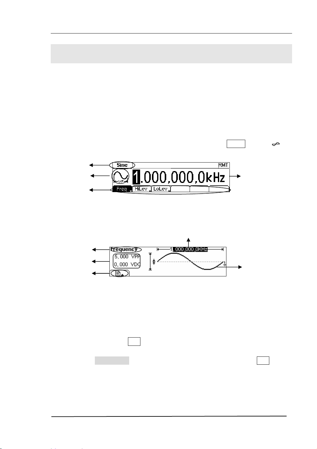
The DG2000 User Interface
DG2000 Series Function/ Arbitrary Waveform Generator provides two display modes:
Menu and Graph. Under the Menu display mode, the display interface is divided into 4
parts: state, waveform icon, operation menu, and parameter display. See figure 1-7.
Under the Graph display mode, you can check the current waveform parameters in the
graphics. The display interface is also divided into 4 parts: state, parameter display,
display menu button and waveform display. See figure 1-8. The operation menu will
appear at the bottom of the screen when you press any menu button. These two
display modes can be switched to each other by pressing the /A button.
State
Waveform
Operation
Menu
Parameter
Figure 1-7 The Interface Instruction of Menu Mode
Display Menu
State
Parameters
button
Parameter
Display
Waveform
Display
Figure 1-8 The Interface Instruction of Graph Mode
Note:
The signs for the buttons in this manual are the same as the panel buttons. Please
note that the signs for the functional buttons on the operation panel are represented
by squared words, such as Sine, which represents the transparent functional key with
Sine on it on the front panel, while the menu buttons are represented by shadow
words such as Frequency , which means the “Frequency” option in the Sine menu.
© 2006 RIGOL Technologies, Inc
User’s Guide for DG2000 Series
1-7
Page 18
RIGOL
To Set a Waveform
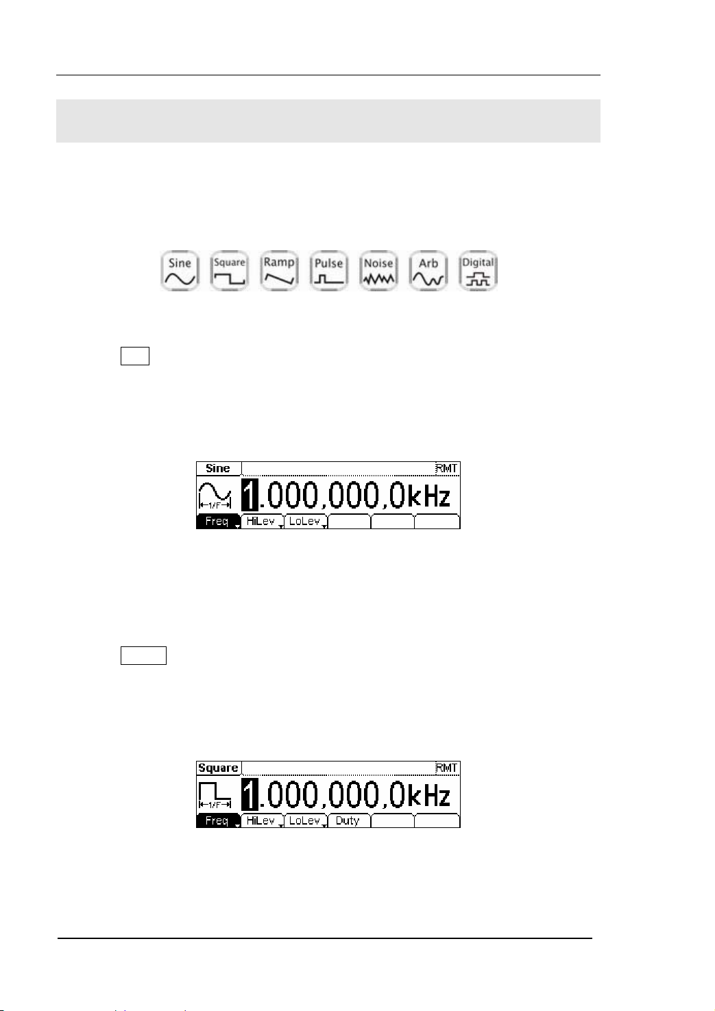
At the left of the operation panel, there is a set of buttons with waveform icon. See
figure 1-9. The exercise below will help you familiarized with the waveform selection
settings. The instructions of the waveform setting are all carried out in the Menu
Display Mode.
Figure 1-9 The Waveform Selection Buttons
1. Press Sine button, and the waveform icon turns into Sine with a “Sine” typeface
in the state area. DG2000 Series Generator can generate Sine signal with
frequency from 1μHz to 40MHz. By setting Frequency/Period, Amplitude/ High
Level, Offset/ Low level, the Sine signal with different parameters can be
generated.
Figure 1-10 The Sine Waveform in the Menu Display Mode
As shown in figure 1-10, the default signal parameters are: 1kHz Frequency, 5.0
pp Amplitude and 0Vdc Offset.
V
2. Press Square button, and the waveform icon turns into Square with a “Square”
typeface in the state area. DG2000 Series Generator can generate Square signal
with frequency from 1μHz to 40MHz and variable duty cycle. By setting
Frequency/Period, Amplitude/ High Level, Offset/ Low level, and Duty Cycle, the
Square signal with different parameters can be generated.
Figure 1-11 The Square Waveform in the Menu Display Mode
As shown in figure 1-11, the default signal parameters are: 1kHz Frequency, 5.0
1-8
User’s Guide for DG2000 Series
© 2006 RIGOL Technologies, Inc
Page 19
RIGOL
Vpp Amplitude, 0 Vdc Offset and 50% Duty Cycle.
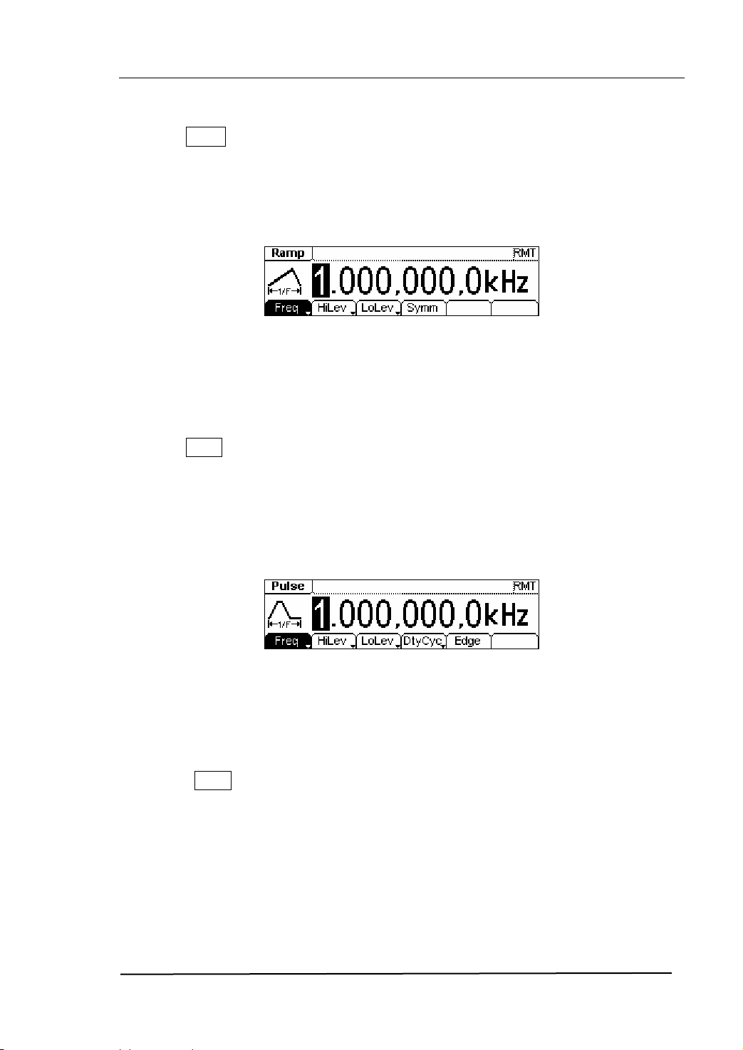
3. Press Ramp button, and the waveform icon turns into Ramp with a “Ramp”
typeface in the state area. DG2000 Series Generator can generate Ramp signal
with frequency from 1μHz to 400 kHz and variable Symmetry. By setting
Frequency/Period, Amplitude/ High Level, Offset/ Low level, and Symmetry, the
Ramp signal with different parameters can be generated.
Figure 1-12 The Ramp Waveform in the Menu Display Mode
As shown in figure 1-12, the default signal parameters are: 1kHz Frequency, 5.0
pp Amplitude, 0 Vdc Offset and 50% Symmetry.
V
4. Press Pulse button, and the waveform icon turns into Pulse with a “Pulse”
typeface in the state area. DG2000 Series Generator can generate Pulse signal
with frequency from 500μHz to 16MHz and variable Pulse Width and Edge Time.
By setting Frequency/Period, Amplitude/ High Level, Offset/ Low level, Pulse
Width and Edge Time, the Pulse signal with different parameters can be
generated.
Figure 1-13 The Pulse Waveform in the Menu Display Mode
As shown in figure 1-13, the default signal parameters are: 1kHz Frequency, 5.0
pp Amplitude, 0 Vdc Offset, 20% Duty Cycle and 50ns Edge Time.
V
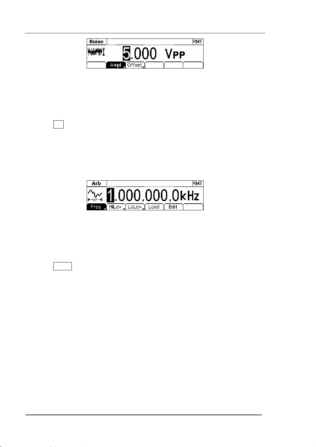
5. Press Noise button, and the waveform icon turns into Noise with a “Noise”
typeface in the state area. DG2000 Series Generator can generate Noise signal
with Band Width up to 20MHz. By setting Amplitude/ High Level, Offset/ Low level,
the Noise signal with different parameters can be generated.
© 2006 RIGOL Technologies, Inc
User’s Guide for DG2000 Series
1-9
Page 20
RIGOL
Figure 1-14 The Noise Waveform in the Menu Display Mode
As shown in figure 1-14, the default signal parameters are: 5.0 V
dc Offset.
0 V
pp Amplitude and
6. Press Arb button, and the waveform icon turns into Arb with an “Arb” typeface in
the state area. DG2000 Series Generator can generate repeatable arbitrary
waveform signals with at most 512K points and 12MHz frequency. By setting
Frequency/Period, Amplitude/ High Level, Offset/ Low level, arbitrary waveform
signals with different parameters can be generated.
Figure 1-15 The Arbitrary Waveform in the Menu Display Mode
As shown in figure 1-15, the default Exponential Rise Signal parameters are: 1kHz
Frequency, 5.0 V
pp Amplitude and 0 Vdc Offset.
7. Press Digital button, and enter the interface of Logic Signal Output Module. For
the detailed explanations, please refer to User’s Guide of DG2000 Logic Signal
Output Module.
1-10
User’s Guide for DG2000 Series
© 2006 RIGOL Technologies, Inc
Page 21
RIGOL
To Set Modulate/ Sweep/Burst
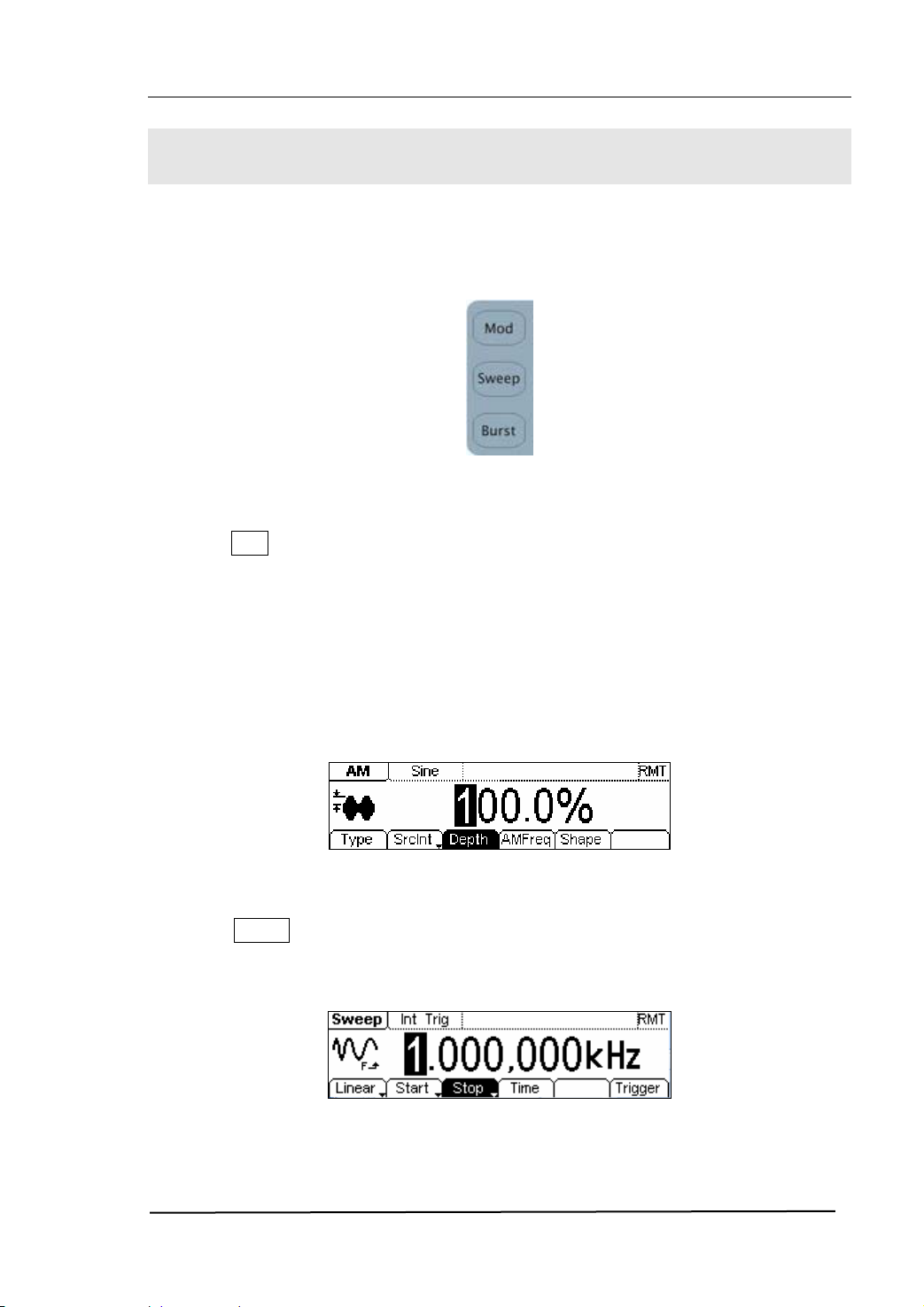
As shown in figure 1-16, there are three buttons on the front panel, which are used for
Modulating, sweeping and bursting settings. The instructions below will help you
familiarize with the setting of these functions.
Figure 1-16 The Modulate/ Sweep/ Burst button
1. Press Mod button, and a Modulated waveforms will be generated.
Parameters are set by using the menu buttons. The modulated waveform can be
changed by changing the parameters such as Type, Internal/External Modulation,
Depth, Frequency, Waveform, etc.
DG2000 Series can modulate waveform by using AM, FM, PM, PWM and FSK. Sine,
Square, Ramp or Arbitrary waveforms can be modulated (Pulse, Noise and DC
cannot be modulated).
Figure 1-17 The Modulated Waveform in the Menu Display Mode
2. Press Sweep button, Sine, Square, Ramp or Arbitrary waveform can be swept
(Pulse, Noise and DC can not be swept).
In the Sweep Mode, DG2000 Series generate signal with variable frequencies.
Figure 1-18 The Sweep Waveform in the Menu Display Mode
© 2006 RIGOL Technologies, Inc
User’s Guide for DG2000 Series
1-11
Page 22
RIGOL
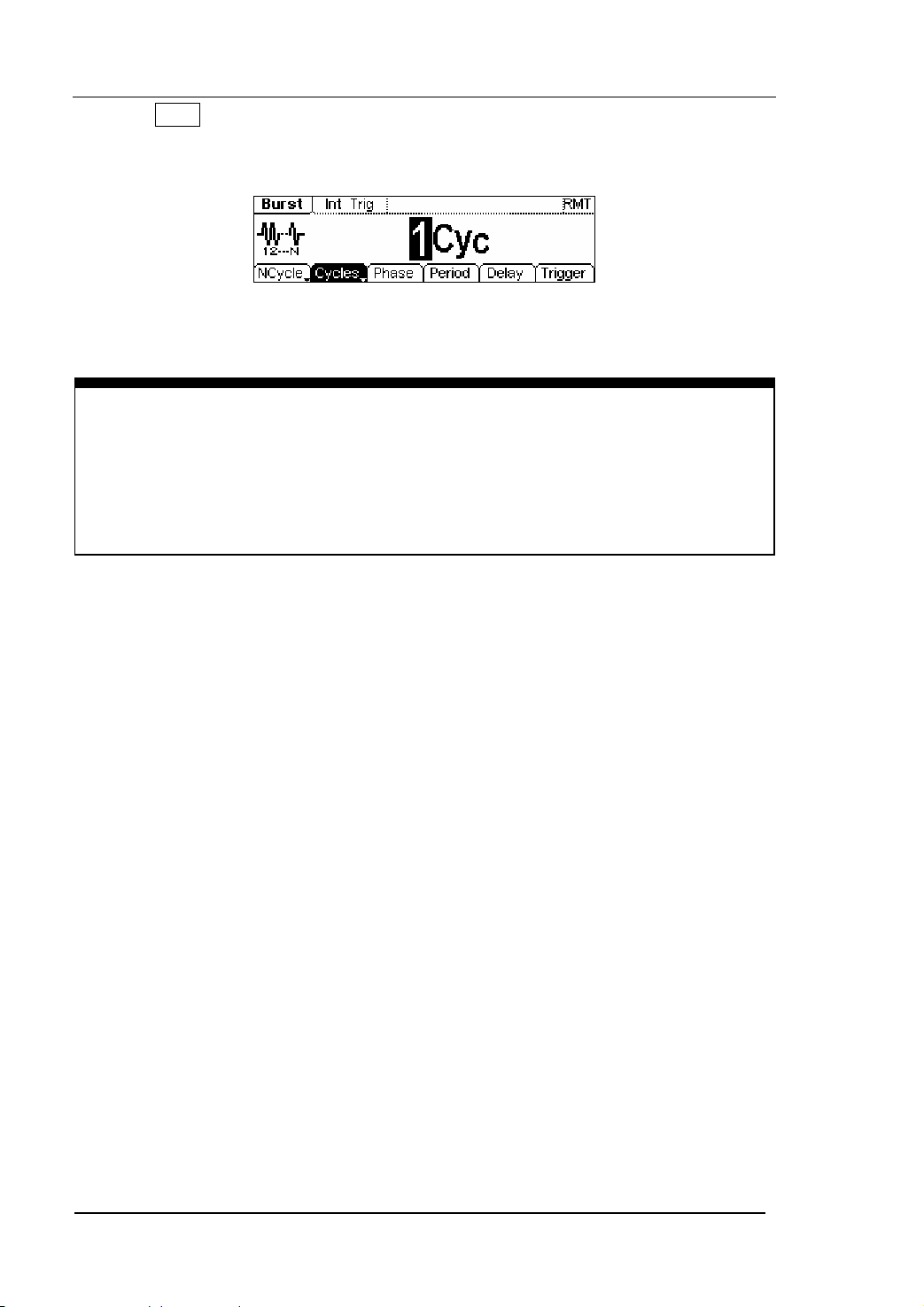
3. Press Burst button, Burst for Sine, Square, Ramp, Pulse or Arbitrary waveform can
be generated (Noise can only be used in the gated Burst).
Figure 1-19 The Burst Waveform in the Menu Display Mode
Term Explanation
Burst:Output Waveforms with set cycle times
Burst can last for certain times of waveform cycle (N-Cycle Burst) or be controlled by
external gated signals (Gated Burst). Burst applies to all kinds of waveforms, but
noise can only be used in gated burst. Generally it is called BURST function within
every Signal Generator.
1-12
User’s Guide for DG2000 Series
© 2006 RIGOL Technologies, Inc
Page 23
RIGOL
To Set Trigger/Output
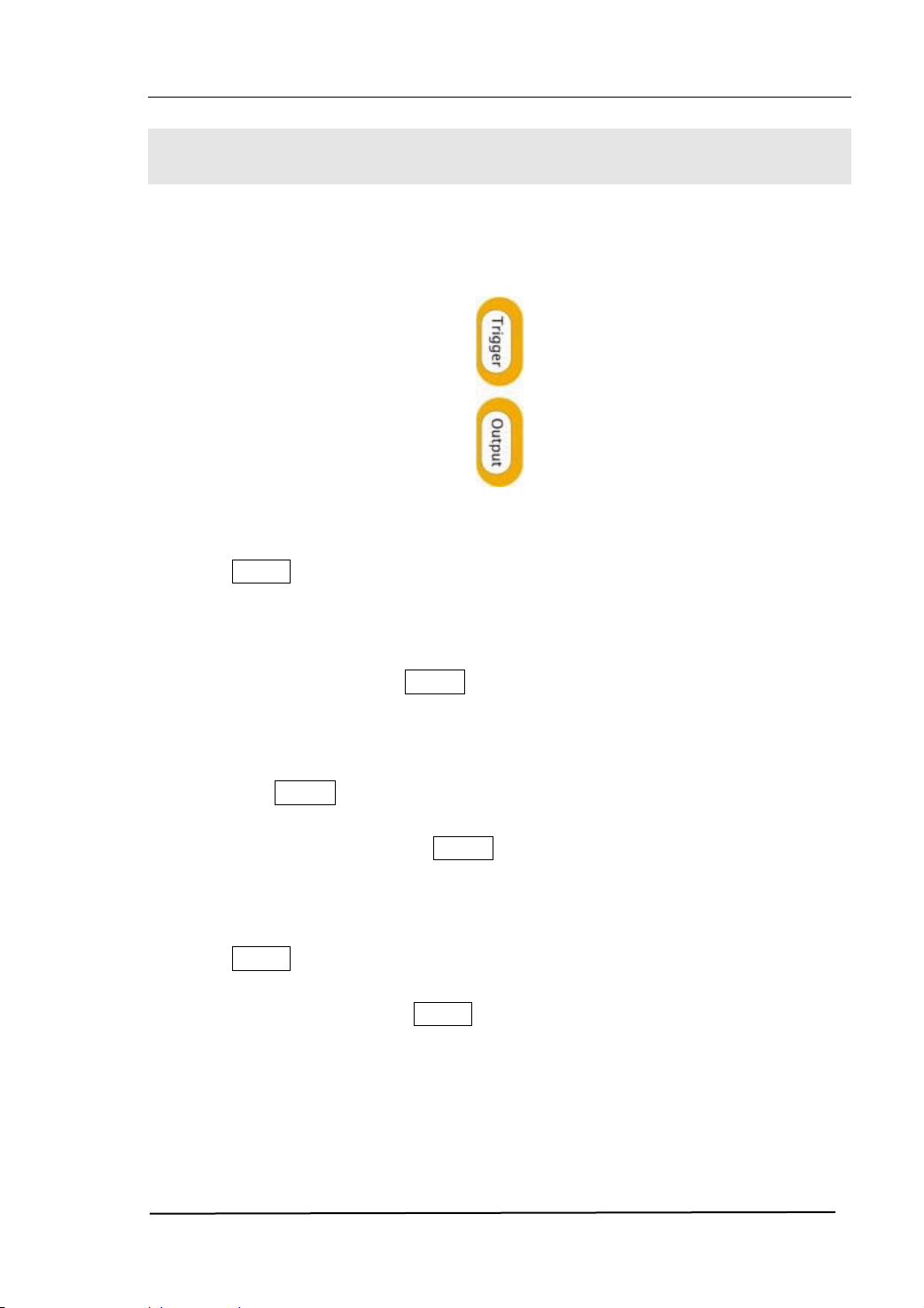
As shown in figure 1-20, there are two buttons on the right side of the operation panel,
which are used to set Trigger and Output Control. The instruction below will help you
familiarize with these functions.
Figure 1-20 The Trigger/Output Button
1. Press Trigger Button, choose internal/external or manual Trigger (Manual Trigger
can only be used in Sweep and N-Cycle Burst)
z The default setting for Trigger is “Internal”. In this mode, when the Sweep or
Burst Mode is also selected, the Generator will continuously generate burst.
At this time, press Trigger button, the instrument will shift from the
“Automatic” Trigger mode into “Manual” Trigger mode.
z When the generator uses the” External” Trigger Mode, if the Sweep or the
Burst Mode is selected, the signal will be continuously generated. At this time,
press Trigger button, the instrument state will not change, and it will show
the information “The instrument has already been triggered”.
z Every time you press the Trigger button, “Manual” Trigger will start a sweep
or generate a burst. Press the button again, and the generator will be
triggered again.
2. Press Output Button, activate or deactivate the output signal.
If an overload message is shown, disconnect the external equipment from the
output terminals and press Output button, reactivate the output terminal.
© 2006 RIGOL Technologies, Inc
User’s Guide for DG2000 Series
1-13
Page 24
RIGOL
To Use Digital Input
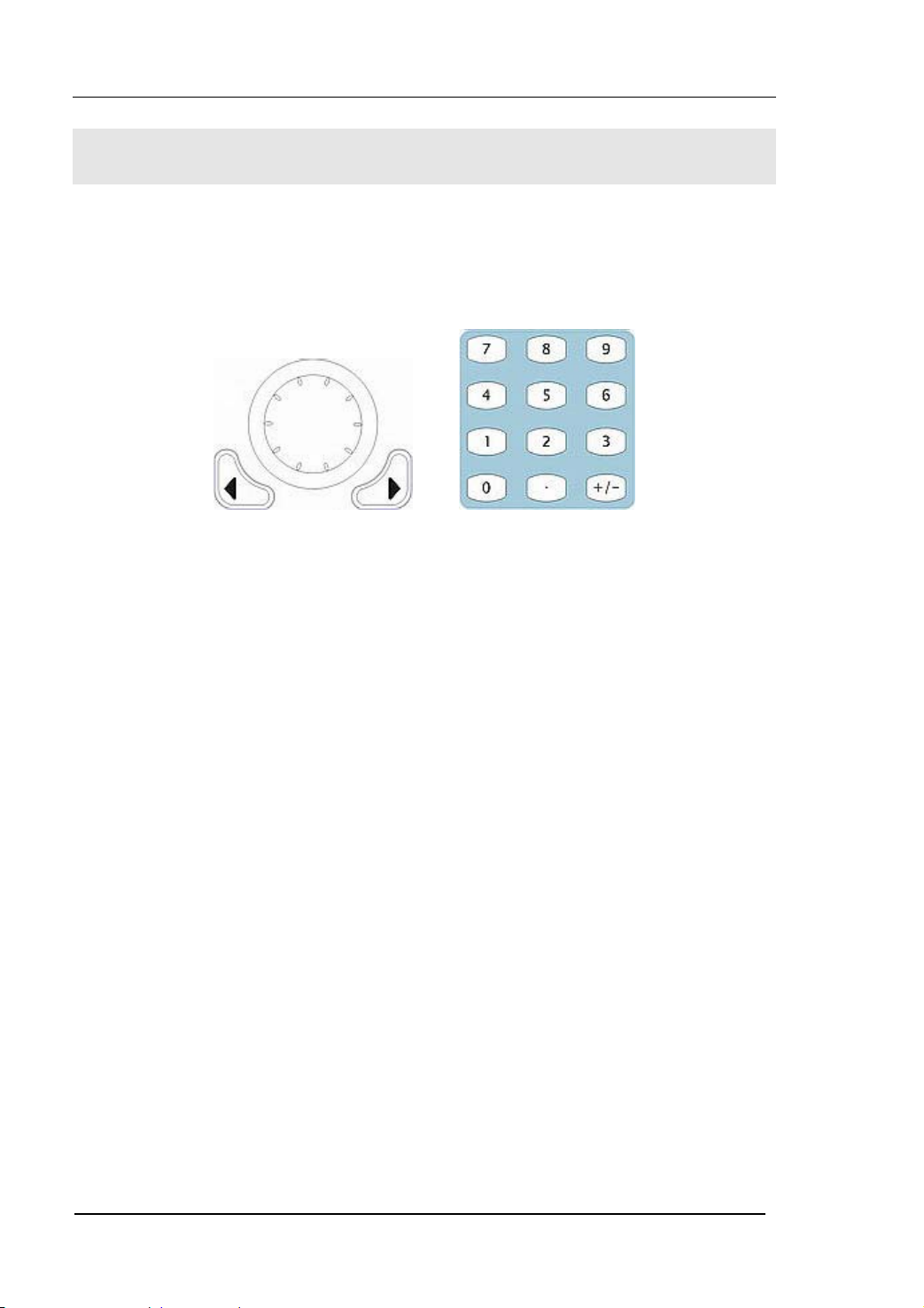
As shown in figure 1-21, there are two groups of buttons on the operation panel,
which are the direction button, the knob and the keypad. The instruction below will
help you familiarize with the Digital Input Function.
(1) Direction Key and the Knob (2) Keyboard
Figure 1-21 The Front Panel Digital Input
1. Use the Direction keys to move the cursor left or right. Rotate the knob to change
a digit (clockwise to increase 1), and the range of digit is 0~9.
2. Use the Keypad to set the parameters values of the waveforms, which can change
its value directly.
1-14
User’s Guide for DG2000 Series
© 2006 RIGOL Technologies, Inc
Page 25
RIGOL
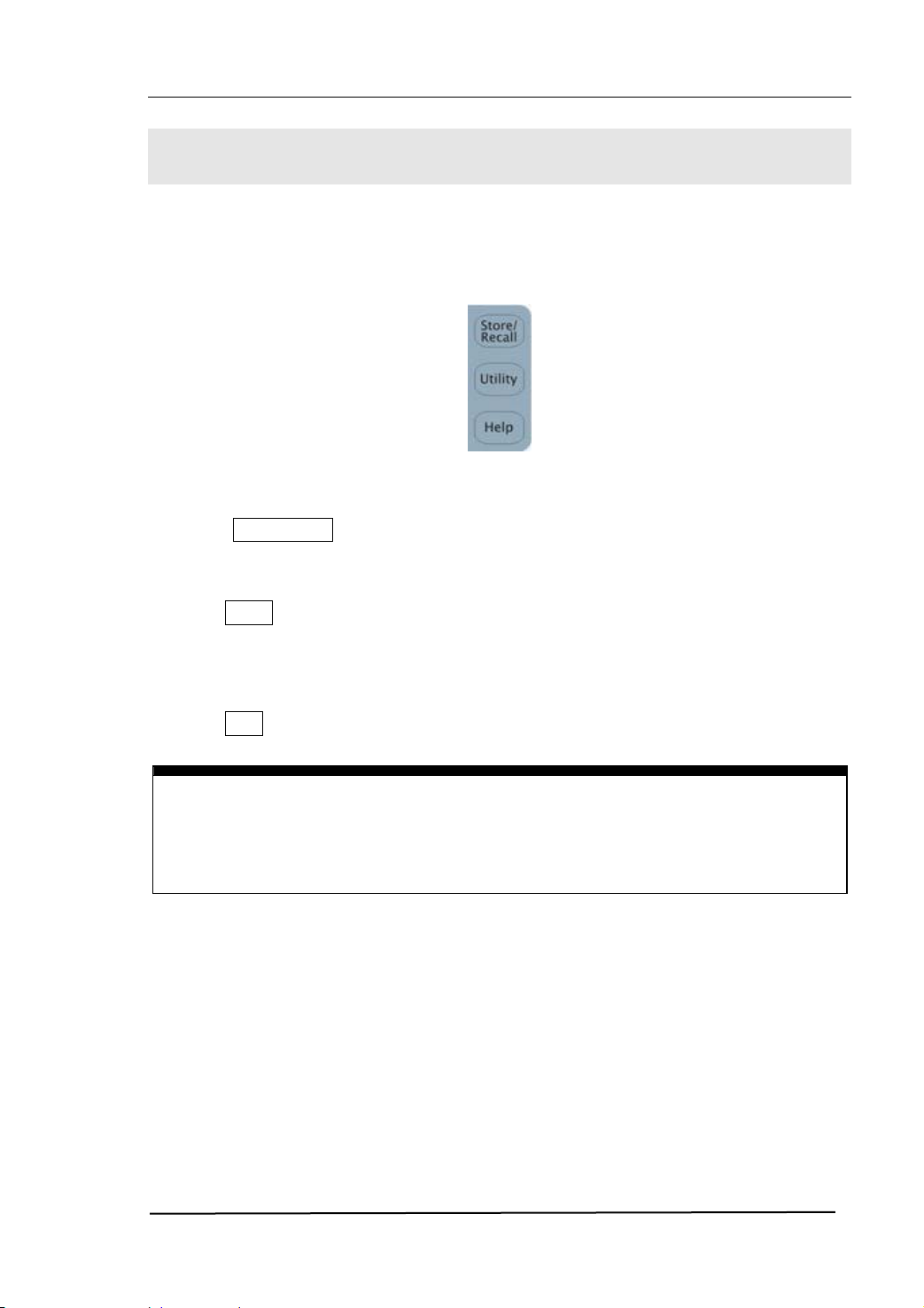
To Use Store/Utility/Help Function
As shown in figure 1-22, there are three buttons on the operation panel, which are
used to call the store/recall, utility and help function. The instruction below will help
you familiarize with these Functions.
Figure 1-22 The Store/Recall, Utility and Help Button
1. The Store/Recall Button is used to store waveform data and configure
information.
2. The Utility Button is used to set the auxiliary system function, change the output
configure parameters, interface setting, system setting information or perform
the instrument self-test and read the calibration information, etc.
3. The Help Button is used to see the help information.
Operation Instruction
To get help:
To get help on any key of the front panel, press the key and last for 1 second, then
the help message will appear.
© 2006 RIGOL Technologies, Inc
User’s Guide for DG2000 Series
1-15
Page 26

Page 27

RIGOL
Chapter 2 Operating Your Generator
Up to now you have got a brief understanding of the front/rear panel, every function
control area and keys of DG2000 series. You should also know how to set your
function/arbitrary waveform generator. If you are not familiar with these operations,
please read Chapter 1 “Getting Started” again.
This chapter covers the following topics:
Menu/Graph Mode ( / A )
Setting Sine Signal ( Sine )
Setting Square Signal ( Square )
Setting Ramp Signal ( Ramp )
Setting Pulse Signal ( Pulse )
Setting Noise Signal ( Noise )
Setting Arb Signal ( Arb )
Settig Logic Signal Output ( Digital ) *
Output Modulated Signal ( Mod )
Output Sweep Signal ( Sweep )
Output Burst Signal ( Burst )
Trigger ( Trigger )
Store/Recall ( Store/Recall )
Utility Setting ( Utility )
Help System ( Help )
You are suggested to read this chapter carefully so as to understand
DG2000 Series Generator‘s versatile waveform setting Functions and the
other operation methods.
*Note: For the operation instruction of Logic Signal Output, please refer to User’s
Guide of DG2000 Logic Signal Output Module.
© 2006 RIGOL Technologies, Inc
User’s Guide for DG2000 Series
2-1
Page 28
RIGOL
The Menu/Graph Mode
To activate the Graph Mode
Press / A to enter the Graph Mode. The name of the current selection parameter is
shown on the top left corner of the screen, and its value is shown in inverse color. See
figure 2-1.
Display Menu
Button
Figure 2-1 The Graph Mode Interface
To Select the Desired Parameter
To select the specific parameters, please press any menu button and the operation
menu will pop out. Press the corresponding button to set the parameter. For example,
if you want to change the frequency, press any menu button and select Freq menu.
The direction button will help you find your desired parameter and change its value
with the knob or the keypad, see figure 2-2. Under the Graph Mode, the parameters
will still switch at a second press on the button, such as Amp/HiLev .
Current
Parameter
Output
Frequency
Amp
Offset
Operation
Menu
Figure 2-2 Setting the parameters in the Graph Mode
To Quit the Graph Mode
To quit the Graph Mode, press the / A again and return the Menu Mode.
2-2
User’s Guide for DG2000 Series
© 2006 RIGOL Technologies, Inc
Page 29

RIGOL
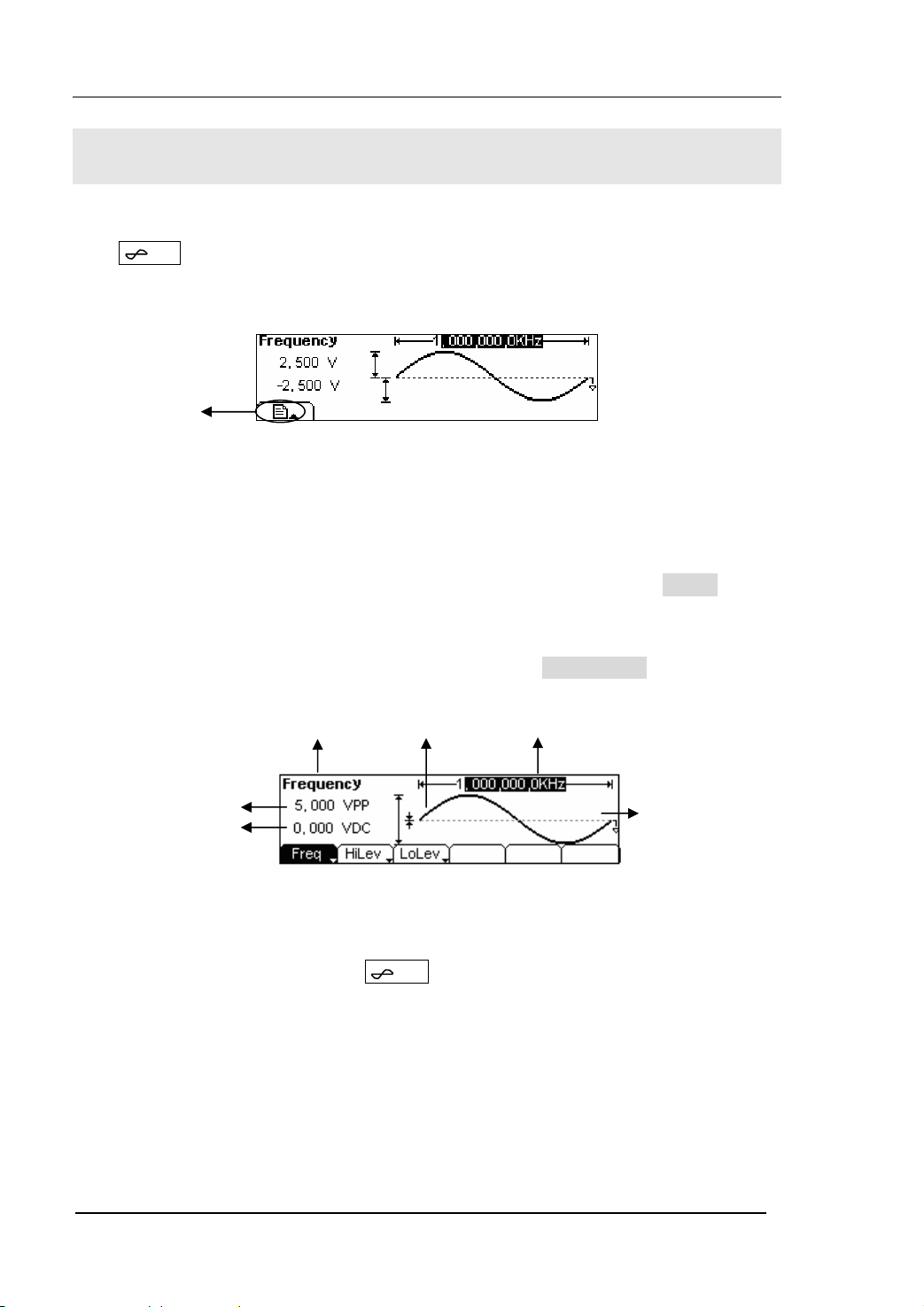
To Set Sine Signals
In the Menu Mode, press Sine button to call the Sine operation. The top left corner of
the screen will show the name of the current waveform, see figure 2-3. The output
Sine waveform parameters are set by using the Sine operation menu.
The parameters for Sine waveforms are: Frequency/ Period, Amplitude/ High Level,
Offset/ Low Level. Different Sine Signals are generated by setting these parameters. As
is shown in figure 2-4, select Freq in the operation menu and the frequency
parameter will show in the parameter area. then Users can change the frequency value
by using the direction button and the knob or the keypad.
Output
Waveform
Operation Menu:
Controlled and
Operated by
menu button
Figure 2-3 The Setting Interface of Sine Signal Parameter
Parameter
Current
Figure 2-4 The Operation Menu
Table 2-1 The Menu Explanations of Sine Signal
Function
Menu
Frequency/
Period
Amplitude/
High Level
Offset/Low
Level
Settings Explanation
Setting the signal frequency or period; the
current parameter will switch at a second press.
Setting the signal Amplitude or High Level; the
current parameter will switch at a second press.
Setting the signal Offset or Low Level; the current
parameter will switch at a second press
© 2006 RIGOL Technologies, Inc
User’s Guide for DG2000 Series
2-3
Page 30
RIGOL
To Set the Output Frequency/Period
1. Press Sine Æ Freq/Period Æ Freq , to set the frequency parameter.
The frequency shown on the screen is the default value when the instrument is
powered or the set value beforehand. When setting the function, if the current
value is valid for the new waveform, it will be used sequentially. If you want to set
the period for the waveform, press Freq/Period button again, switch to the
Period parameter (The current operation is displayed in inverse color).
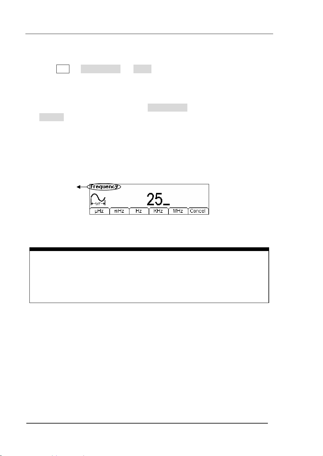
2. Input the Desired Frequency.
Use the keypad to input the parameter value directly, and press the corresponding
button to select the parameter unit. Or you can use the direction button to select
the digit you want to edit, and then use the knob to change its value.
Current
Parameter:
Frequency
Figure 2-5 Setting the Frequency
Instruction:
When using the keypad to enter the digit, you can use the Left direction button to
move the cursor backward and delete or change the value of the previous digit.
When using the knob to input, use the direction buttons to select the digit you
want to edit and rotate the knob to change its value.
2-4
User’s Guide for DG2000 Series
© 2006 RIGOL Technologies, Inc
Page 31

RIGOL
To Set the Output Amplitude
1. Press Sine Æ Ampl/HiLev Æ Ampl , to set the amplitude.
The amplitude shown on the screen is the default value when the instrument is
powered or the set value beforehand. When changing the function, if the current
value is valid for the new waveform, it will be used sequentially. If you want to set
the waveform by high Level or Low Level, press Ampl/HiLev or Offset/Lolev
again, switch to HiLev or LoLev parameter (The current operation is
displayed in inverse color).
2. Input the Desired Amplitude
Use the keypad or the knob to input the desired value, choose the unit, and press
the corresponding button.
Current
Parameter:
Amplitude
Figure 2-6 Setting the Amplitude
© 2006 RIGOL Technologies, Inc
User’s Guide for DG2000 Series
2-5
Page 32

RIGOL
To Set the DC Offset
1. Press Sine Æ Offset/LoLev Æ Offset , to set the offset.
The offset shown on the screen is the default value when the instrument is
powered or the set value beforehand. When changing the function, if the current
value is valid for the new waveform, it will be used sequentially.
2. Input the Desired Offset
Use the keypad or the knob to input the desired value, choose the unit, and press
the corresponding button.
In the Graph Mode, the waveform is shown in figure 2-8.
Current
Parameter:
Offset
Figure 2-7 Setting the Offset
Figure 2-8 The Waveform Parameter in the Graph Mode
Notes: the Setting of any waveform for DC Offset is the same as sine wave, so we will
not cover this topic hereon.
2-6
User’s Guide for DG2000 Series
© 2006 RIGOL Technologies, Inc
Page 33
RIGOL
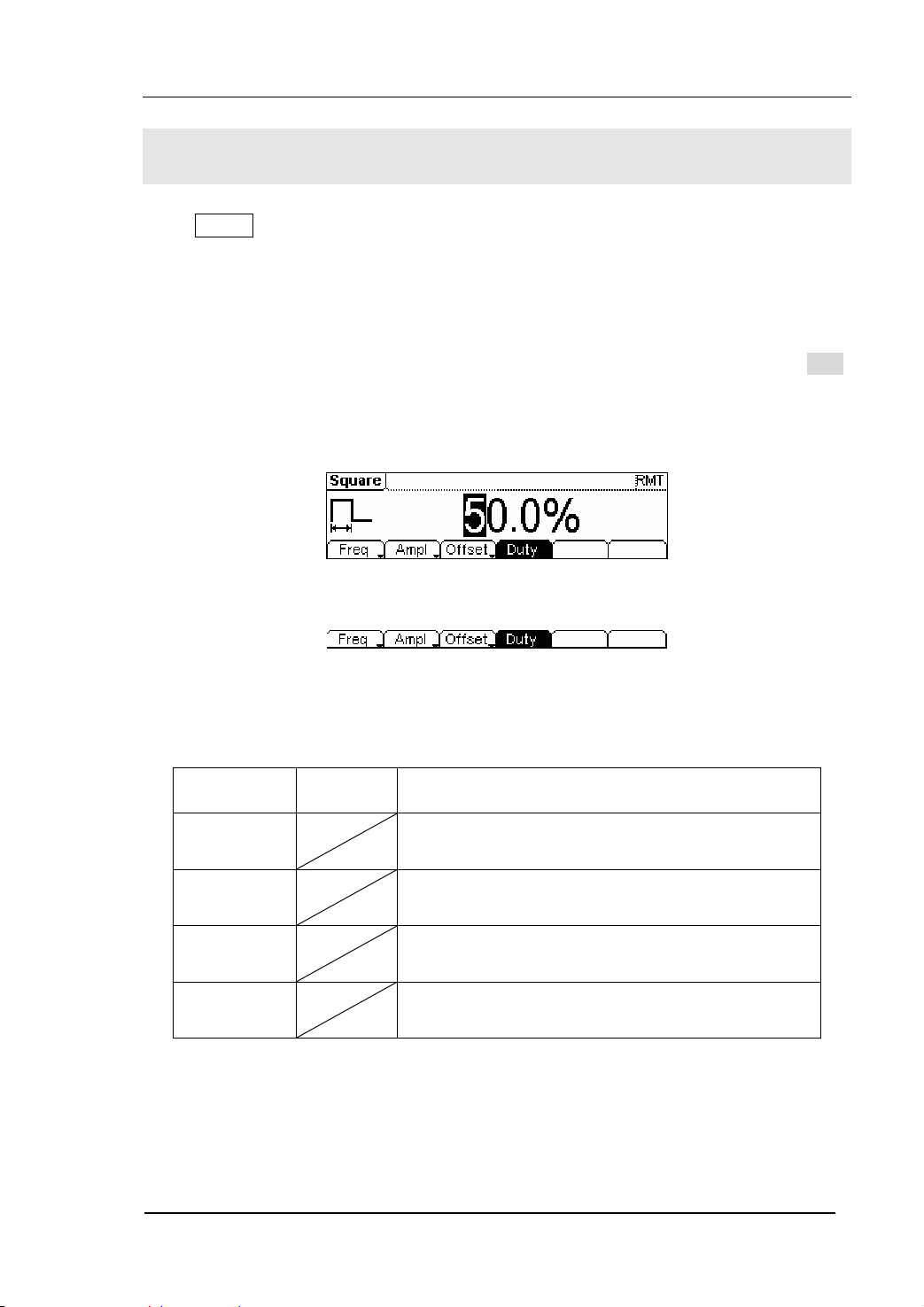
To Set Square Signals
Press Square button, in the Normal Mode, the operation menu will appear at the
bottom of the screen, see figure 2-9. Set the Square parameters by using the
operation menu.
The parameters for Square waveforms are: Frequency/ Period, Amplitude/ High Level,
Offset/ Low Level and Duty Cycle. See figure 2-10. In the operation menu, select Duty,
and the corresponding parameter will be displayed in inverse color for which users can
make a change.
Figure 2-9 The Setting Interface of Square Signal
Figure 2-10 The Operation Menu
Table 2-2 The Menu Explanations of Square Signal
Function
Menu
Frequency/
Period
Amplitude/
High Level
Offset/Low
Level
Duty Cycle Setting the Duty Cycle for Square Waveform
Settings Explanation
Setting the signal frequency or period; the current
parameter will switch at a second press.
Setting the signal Amplitude or High Level; the
current parameter will switch at a second press.
Setting the signal Offset or Low Level; the current
parameter will switch at a second press
© 2006 RIGOL Technologies, Inc
User’s Guide for DG2000 Series
2-7
Page 34

RIGOL
Term Explanation:
Duty Cycle: The percentage that the High Level takes up in the whole Period.
Please Note : for the Frequency Duty Cycle Value
Below 8MHz: 20% to 80%
From 8MHz to 16MHz (included): 40% to 60%
Higher than 16MHz: 50%
2-8
User’s Guide for DG2000 Series
© 2006 RIGOL Technologies, Inc
Page 35

RIGOL
To Set the Duty Cycle
1. Press Square Æ Duty , to set the Duty Cycle.
The Duty Cycle shown on the screen is the default value when the instrument is
powered or the set value beforehand. When changing the function, if the current
value is valid for the new waveform, it will be used sequentially.
2. Input the Desired Duty Cycle
Use the keypad or the knob to input the desired value, choose the unit, and press
the corresponding button. The Generator will change the waveform immediately.
Current
Parameter:
Duty Cycle
Figure 2-11 Setting the Duty Cycle
In the Graph Mode, the waveform is shown in figure 2-12.
Figure 2-12 The Waveform Parameter in the Graph Mode
© 2006 RIGOL Technologies, Inc
User’s Guide for DG2000 Series
2-9
Page 36
RIGOL
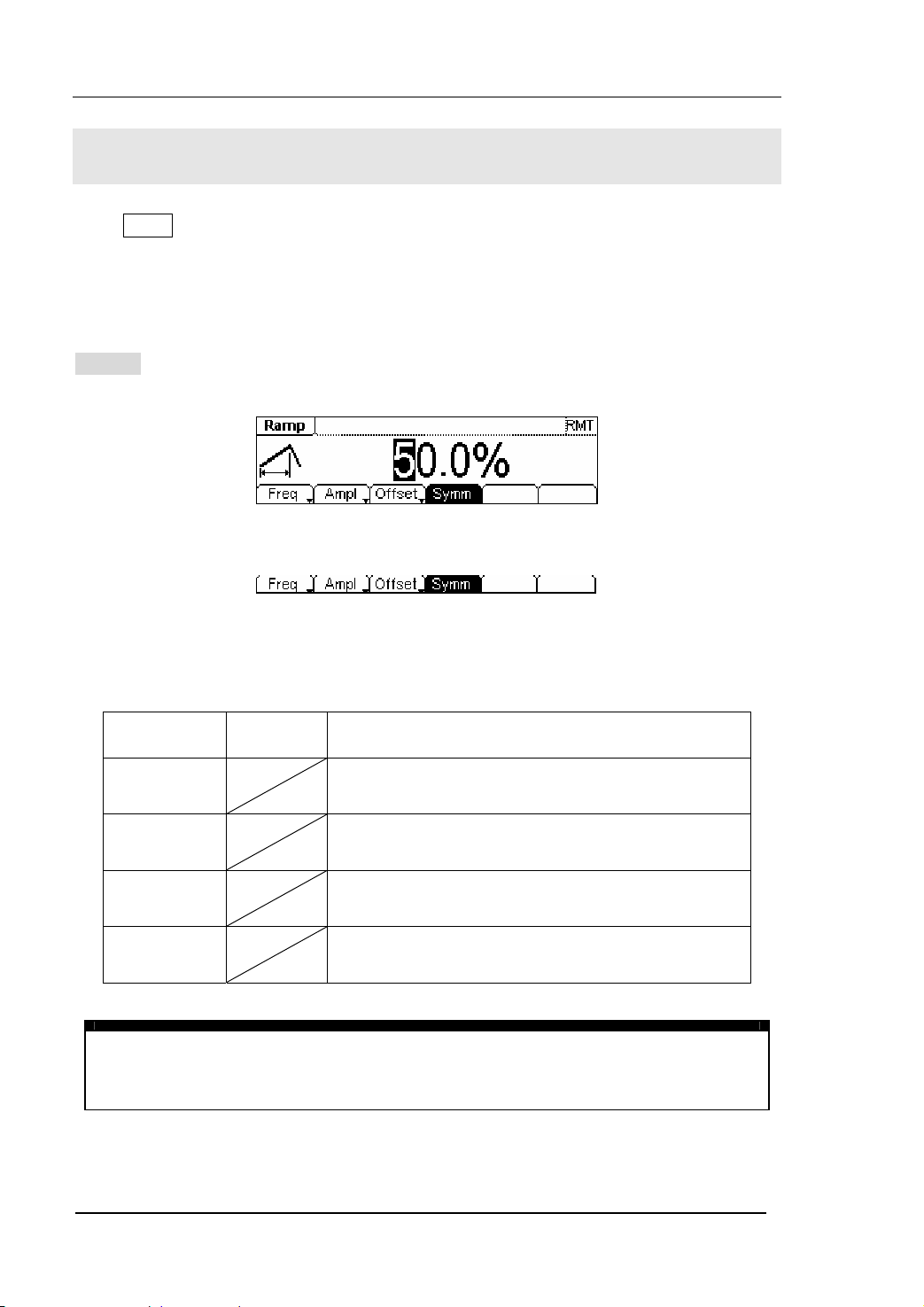
To Set Ramp Signals
Press Ramp button, in the Normal Mode, the operation menu will appear at the bottom
of the screen, see figure 2-13. Set the Ramp parameters by using the operation menu.
The parameters for Ramp waveforms are: Frequency/ Period, Amplitude/ High Level,
Offset/ Low Level and Symmetry. See figure 2-14. In the operation menu, select
Symm , and the corresponding parameter will be displayed in inverse color for which
users can make a change.
Figure 2-13 The Setting Interface of Ramp Signal
Figure 2-14 The Operation Menu
Table 2-3 The Menu Explanations of Ramp Signal
Function
Menu
Frequency/
Period
Amplitude/
High Level
Offset/Low
Level
Symmetry Setting the Symmetry for Ramp Waveform
Term Explanation:
Symmetry: The percentage that the Rising Period takes up in the whole Period.
Input Range: 0~100%
Settings Explanation
Setting the signal frequency or period; the current
parameter will switch at a second press.
Setting the signal Amplitude or High Level; the
current parameter will switch at a second press.
Setting the signal Offset or Low Level; the current
parameter will switch at a second press
2-10
User’s Guide for DG2000 Series
© 2006 RIGOL Technologies, Inc
Page 37
RIGOL
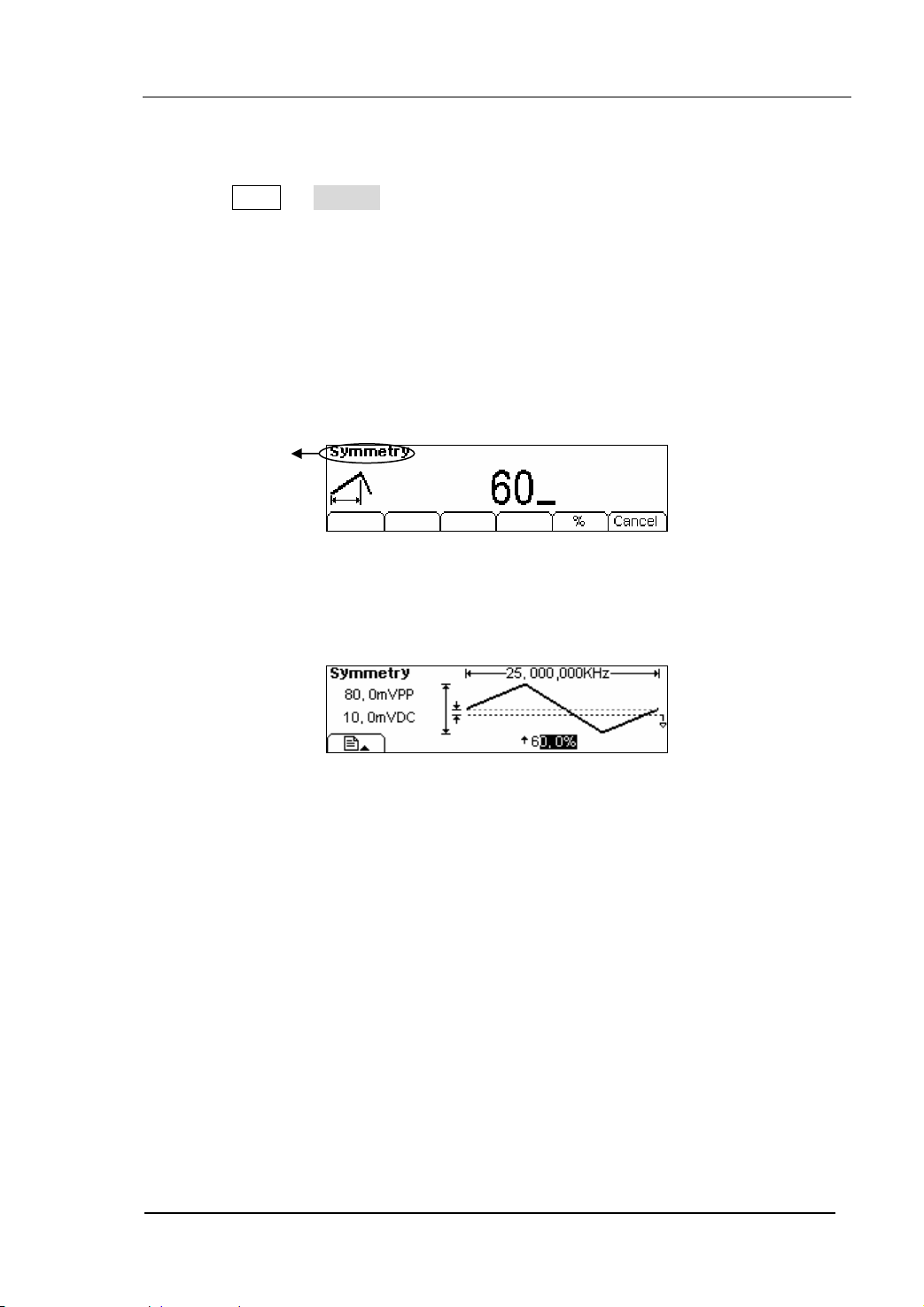
To Set the Symmetry
1. Press Ramp Æ Symm , to set the Symmetry.
The Symmetry shown on the screen is the default value when the instrument is
powered or the set value beforehand. When changing the function, if the current
value is valid for the new waveform, it will be used sequentially.
2. Input the Desired Symmetry.
Use the keypad or the knob to input the desired value, choose the unit, and press
the corresponding button. The Generator will change the waveform immediately.
In the Graph Mode, the waveform is shown in figure 2-16.
Current
Parameter:
Symmetry
Figure 2-15 Setting the Symmetry
Figure 2-16 The Waveform Parameter in the Graph Mode
© 2006 RIGOL Technologies, Inc
User’s Guide for DG2000 Series
2-11
Page 38
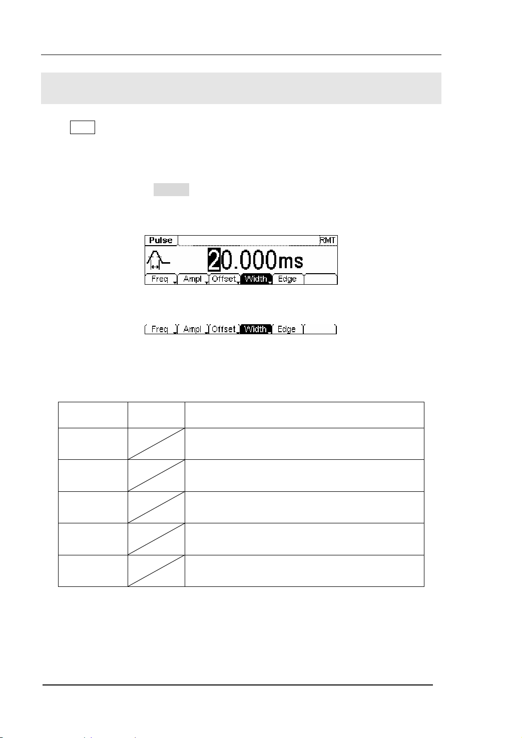
RIGOL
To Set Pulse Signals
Press Pulse button, in the Normal Mode, the operation menu will appear at the bottom
of the screen, see figure 2-17. Set the Pulse parameters by using the operation menu.
The parameters for Pulse waveforms are: Frequency/ Period, Amplitude/ High Level,
Offset/ Low Level, Pulse Width/Duty Cycle and Edge Time. See figure 2-18. In the
operation menu, select Width , and the corresponding parameter will be displayed in
inverse color for which users can make a change.
Figure 2-17 The Setting Interface of Pulse Signal
Figure 2-18 The Operation Menu
Table 2-4 The Menu Explanations of Pulse Signal
Function
Menu
Frequency/
Period
Amplitude/
High Level
Offset/Low
Level
Width/
Dty Cyc
Edge Setting the Edge Time for Pulse Waveform.
Settings Explanation
Setting the signal frequency or period; the current
parameter will switch at a second press.
Setting the signal Amplitude or High Level; the
current parameter will switch at a second press.
Setting the signal Offset or Low Level; the current
parameter will switch at a second press.
Setting the signal Pulse Width or Duty Cycle; the
current parameter will switch at a second press.
2-12
User’s Guide for DG2000 Series
© 2006 RIGOL Technologies, Inc
Page 39

RIGOL
Term Explanation:
Pulse Width:
Positive Pulse Width: the time span between thresholds of 50% of the rising edge
amplitude to the next 50% of the falling edge amplitude;
Negative Pulse Width: the time span between thresholds of 50% of the falling
edge amplitude to the next 50% of the rising edge amplitude.
Edge Time:
The time span between the thresholds of the 10% to 90% of the rising edge
amplitude is called Rising Time.
The time span between the thresholds of the 10% to 90% of the falling edge
amplitude is called Falling Time.
The Rising Time and the Falling Time together are called Edge Time.
© 2006 RIGOL Technologies, Inc
User’s Guide for DG2000 Series
2-13
Page 40

RIGOL
To Set the Pulse Width
1. Press Pulse Æ Width , to set the Pulse Width.
The Pulse Width shown on the screen is the default value when the instrument is
powered or the set value beforehand. When changing the function, if the current
value is valid for the new waveform, it will be used sequentially.
2. Input the Desired Pulse Width
Use the keypad or the knob to input the desired value, choose the unit, and press
the corresponding button. The Generator will change the waveform immediately.
Current
Parameter:
Pulse Width
Figure 2-19 Setting the Pulse Width
2-14
User’s Guide for DG2000 Series
© 2006 RIGOL Technologies, Inc
Page 41

RIGOL
To Set the Edge Time
1. Press Pulse Æ Edge , to set the Edge Time.
The Edge Time shown on the screen is the default value when the instrument is
powered or the set value beforehand. When changing the function, if the current
value is valid for the new waveform, it will be used sequentially.
2. Input the desired Edge Time
Use the keypad or the knob to input the desired value, choose the unit, and press
the corresponding button. The Generator will change the waveform immediately.
Current
Parameter:
Edge Time
Figure 2-20 Setting the Edge Time
In the Graph Mode, the waveform is shown in figure 2-21.
Figure 2-21 The Waveform Parameter in the Graph Mode
Instruction:
The system has the default setting that the Rising and Falling edge time are the
same.
© 2006 RIGOL Technologies, Inc
User’s Guide for DG2000 Series
2-15
Page 42
RIGOL
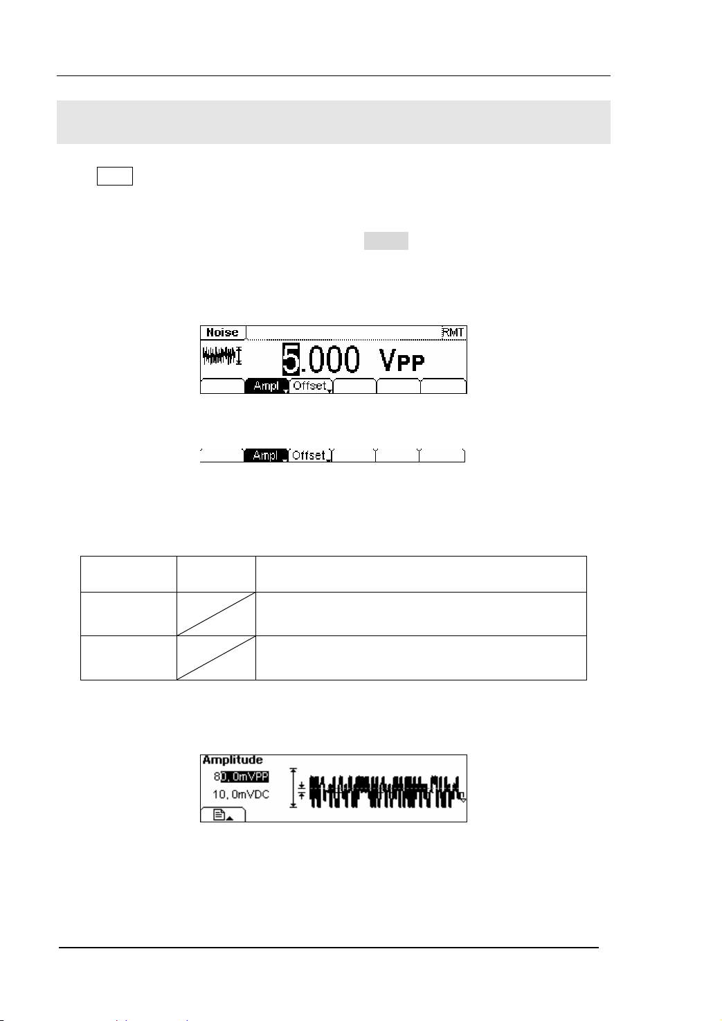
To Set Noise Signals
Press Noise button, in the Normal Mode, the operation menu will appear at the bottom
of the screen, see figure 2-22. Set the Pulse parameters by using the operation menu.
The parameters for Noise waveforms are: Amplitude/ High Level and Offset/ Low Level.
See figure 2-23. In the operation menu, select Ampl , and the corresponding
amplitude will be displayed in inverse color for which users can make a change for the
the amplitude of Noise. And Noise signal has no frequency or period.
Figure 2-22 The Setting Interface of Noise Signal
Figure 2-23 The Operation Menu
Table 2-5 The Menu Explanations of Noise Signal
Function
Menu
Amplitude/
High Level
Offset/Low
Level
Settings Explanation
Setting the signal Amplitude or High Level; the
current parameter will switch at a second press.
Setting the signal Offset or Low Level; the current
parameter will switch at a second press.
In the Graph Mode, the waveform is shown in figure 2-24.
Figure 2-24 The Waveform Parameter in the Graph Mode
2-16
User’s Guide for DG2000 Series
© 2006 RIGOL Technologies, Inc
Page 43

RIGOL
To Set Arbitrary Signals
Press Arb button, in the Normal Mode, the operation menu will appear at the bottom of
the screen, see figure 2-25. Set the Arbitrary Waveform parameters by using the
operation menu.
Arbitrary Signals are divided into two categories: the built-in optional system
waveforms and the user-defined arbitrary waveforms. The parameters for Arbitrary
Waveforms are: Frequency/ Period, Amplitude/ High Level and Offset/ Low Level. See
figure 2-26. In the operation menu, select Freq , and the corresponding frequency
will be displayed in inverse color for which users can make a change.
Figure 2-25 The Setting Interface of Arbitrary Signal
Figure 2-26 The Operation Menu
Table 2-6 The Menu Explanations of Arbitrary Signal
Function
Menu
Frequency/
Period
Amplitude/
High Level
Offset/Low
Level
Load Select the built-in Arbitrary Signal for Output.
Edit Create and Edit Arbitrary Waveform.
Settings Explanation
Setting the signal frequency or period; the current
parameter will switch at a second press.
Setting the signal Amplitude or High Level; the
current parameter will switch at a second press.
Setting the signal Offset or Low Level; the current
parameter will switch at a second press.
© 2006 RIGOL Technologies, Inc
User’s Guide for DG2000 Series
2-17
Page 44
RIGOL
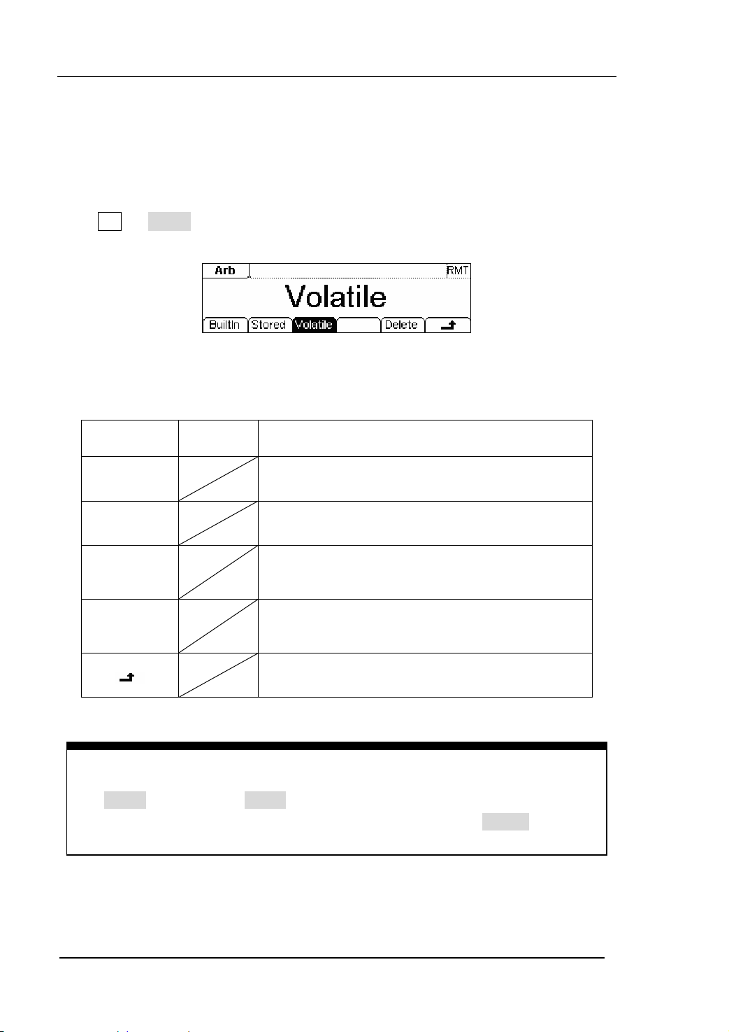
To Select the built-in Arbitrary Waveform
There are five built-in Arbitrary Waveforms and user-defined Arbitrary Waveforms in
the Generator. To select one of them, following the instructions below:
Press Arb Æ Load , to enter into the interface shown below.
Figure 2-27 The Operation Menu
Table 2-7 The Selection Menu of Built-in Arbitrary Waveform
Function
Menu
Built-in
Stored
Settings Explanation
Select one of the five built-in Arbitrary Waveforms
(See Table 2-8)
Select one of Arbitrary Waveforms stored in the
Non-volatile memory.
Select one of Arbitrary Waveforms stored in the
Volatile
Volatile memory. When a new waveform is
created, the old one will be erased.
Delete one of the Arbitrary Waveforms stored in
Delete
the Non-volatile memory. The five Built-in
Waveforms can not be deleted.
Cancel the current operation, and return to the
upper menu. (The followings are the same)
Instructions:
z When there is no waveform stored in the Non-Volatile Memory, the
Stored Menu and the Delete Menu will hide.
z When there is no waveform in the Volatile Memory, the Volatile menu will
hide.
2-18
User’s Guide for DG2000 Series
© 2006 RIGOL Technologies, Inc
Page 45
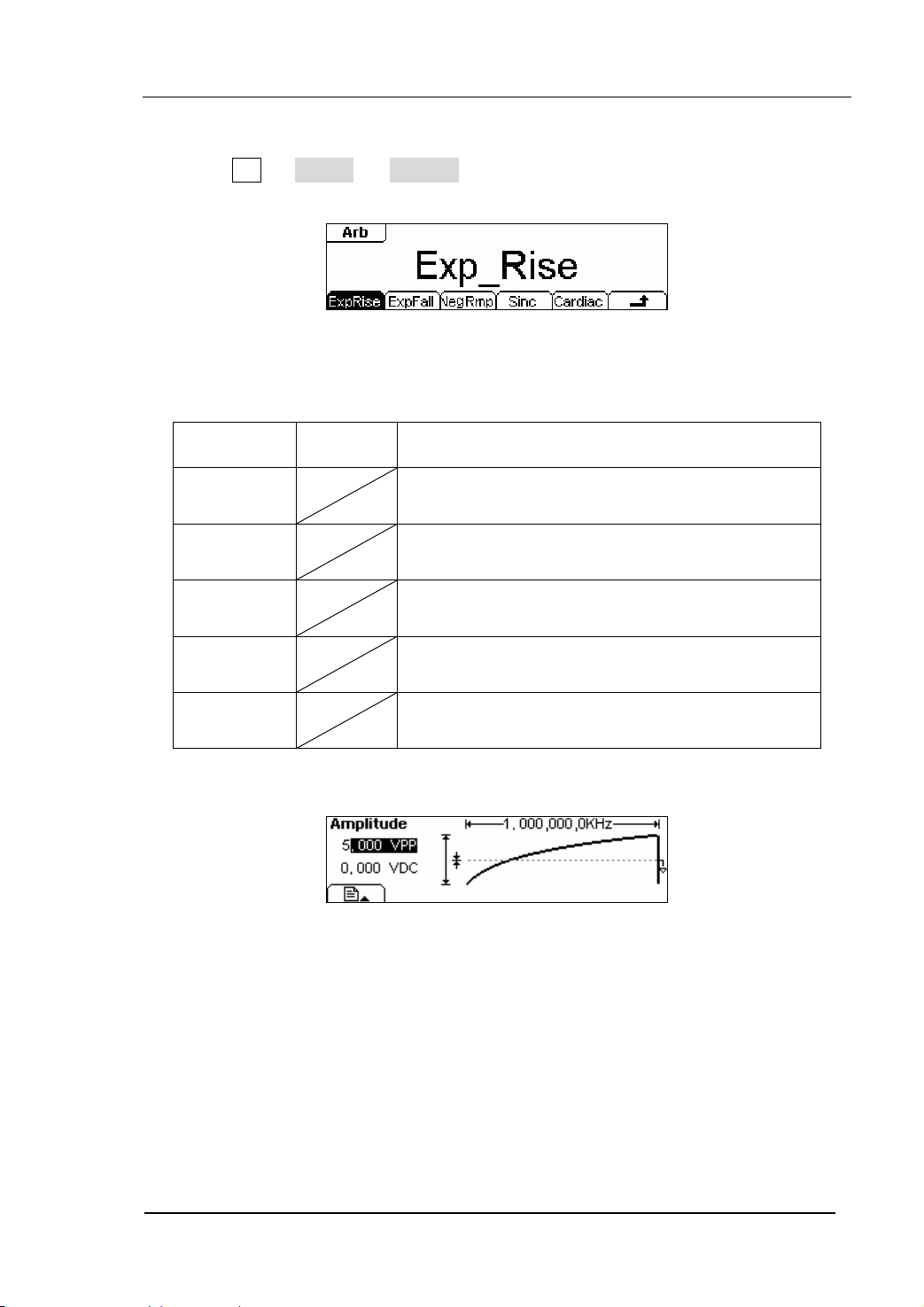
1. To Select the Built-in Waveform
Press Arb Æ Load Æ BuiltIn , and enter into the following interface.
Figure 2-28 The Operation Menu
Table 2-8 The Built-in Arbitrary Waveforms Menu
RIGOL
Function
Menu
ExpRise
ExpFall
Settings Explanation
Select the built-in Exponential Rise Waveform
Select the built-in Exponential Fall Waveform
NegRamp
Sinc
Select the built-in Negative Ramp Waveform
Select the built-in Sinc Waveform. Sinc=Sin(x)/x
Cardiac Select the built-in Cardiac Waveform
In the Graph Mode, the waveform is shown in figure 2-29.
Figure 2-29
The Waveform Parameter in the Graph Mode (Exponential Rising Waveform)
© 2006 RIGOL Technologies, Inc
User’s Guide for DG2000 Series
2-19
Page 46
RIGOL
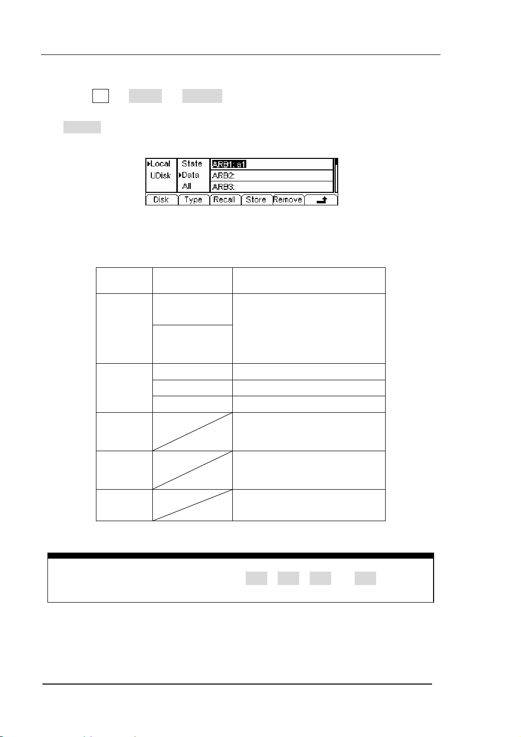
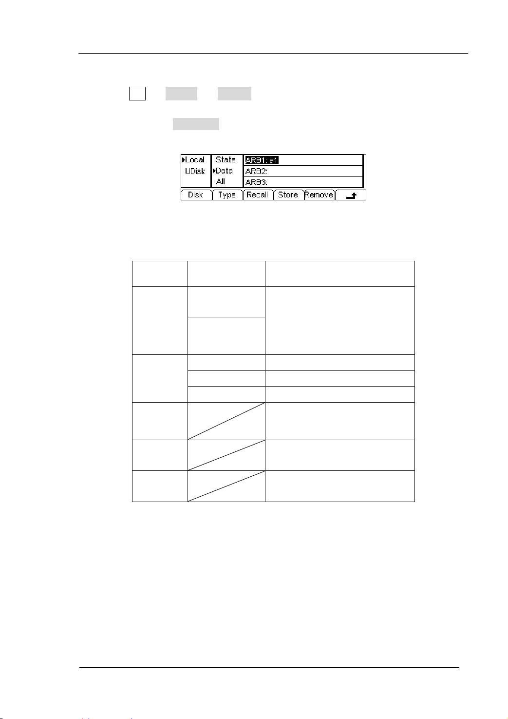
2. To Select the Stored Waveform
Press Arb Æ Load Æ Stored , and enter the following interface. Select the
desired waveform document which will be displayed in inverse color and press
Recall to recall it from the memory.
Figure 2-30 The Operation Menu
Table 2-9 The Stored Arbitrary Waveform Menu
Function
Menu
Settings Explanation
Local
Disk
U Disk
Select display route for the
system information
(When U Disk
is connected )
Setting of the Generator
Arbitrary waveform file
All types of documentation
Type
State
Data
All
Recall the waveform or Setting
Recall
information in the specific
position in the memory.
Store
Remove
Save the waveform to the
appointed place( See Table
2-24)
Remove any waveform that
has been stored in the memory
Instructions:
When there is no waveform stored in the Arb1、Arb2、Arb3 and Arb4, this menu
will hide (The followings is the same and will not explain again)
2-20
User’s Guide for DG2000 Series
© 2006 RIGOL Technologies, Inc
Page 47
RIGOL
3. To Remove the Waveform
Press Arb Æ Load Æ Store , and enter the following interface. Select the
waveform documentation to be deleted which will be displayed in inverse color,
and then press Remove to delete it.
Figure 2-31 The Operation Menu
Table 2-10 The Menu Explanations of Waveform Removal
Function
Menu
Disk
Type
Recall
Store
Remove
Settings Explanation
Local
Select display route for the
U Disk
system information
(When U disk
is connected )
State
Data
All
Setting of the Generator
Arbitrary waveform file
All types of documentation
Recall the waveform or Setting
information in the specific
position in the memory.
Save the waveform to the
appointed position
Remove any waveform that
has been stored in the memory
© 2006 RIGOL Technologies, Inc
User’s Guide for DG2000 Series
2-21
Page 48

RIGOL
To Edit the Arbitrary Waveform
The Generator allows users to edit Arbitrary Waveforms, which can create any new
waveform by initializing points. The operation steps are as follows:
Press Arb Æ Edit , enter the interface shown below.
Figure 2-32 The Operation Menu
Table 2-11 The Menu Explanations of Waveform Edition
Function
Menu
Creat
Stored
Volatile
Delete
Settings Explanation
Create a new waveform, and erase the waveform
in the Volatile memory.
Edit the waveform stored in the non-Volatile
memory
Edit the waveform stored in the Volatile memory
Delete one of the Arbitrary Waveforms stored in
the Non-volatile memory. But The five Built-in
Waveforms can not be deleted.
Instructions:
z When there is no waveform stored in the Non-Volatile Memory, the Stored
Menu and the Delete Menu will hide.
z When there is no waveform in the Volatile Memory, the Volatile menu will
hide.
2-22
User’s Guide for DG2000 Series
© 2006 RIGOL Technologies, Inc
Page 49
RIGOL
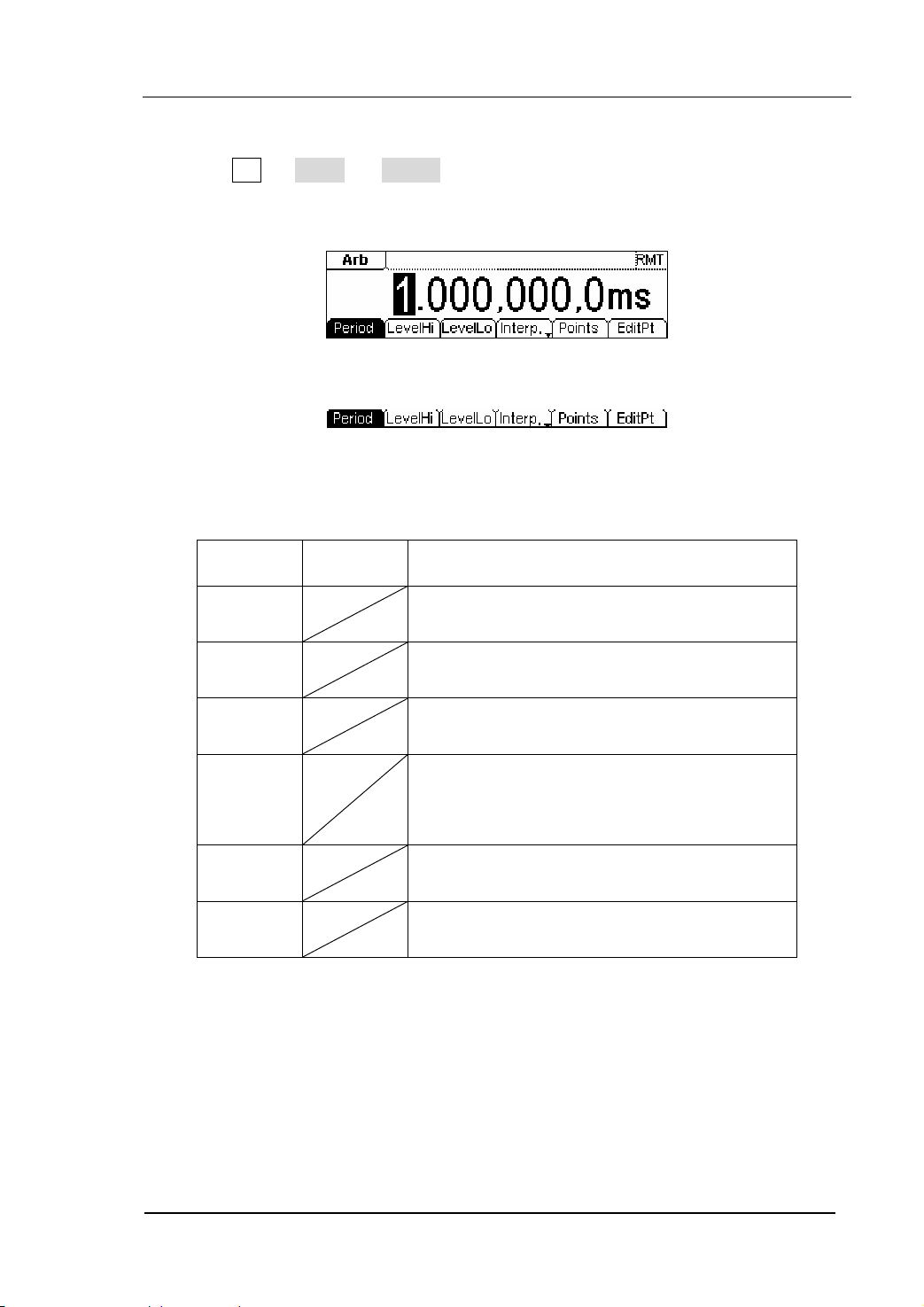
1. To Create a New Waveform
Press Arb Æ Edit Æ Creat , to set the overall parameters for the waveform.
The setting interface is shown in figure2-33 and the menu in table 2-12.
Figure 2-33 The Interface of setting the new waveform parameters
Figure 2-34 The Operation Menu
Table 2-12 The Explanations of Waveform Parameters
Function
Menu
Settings Explanation
Period Setting the Period for the Waveform
LevelHi Setting the Level High for the Waveform
LevelLo
Setting the Level Low for the Waveform
Activate the linear Interpolation between the
Interp On/
Off
defined points
Deactivate the linear Interpolation between
the defined points
Points
Set the number of points when Initializing
the waveform
EditPt Start the Waveform Editor
© 2006 RIGOL Technologies, Inc
User’s Guide for DG2000 Series
2-23
Page 50

RIGOL
To Set the Point Number
Press Points , set the number of the initializing points.
When a new waveform is created, the waveform editor will firstly create a waveform
with two points. The Waveform Editor connects the last point to the Voltage Level of
point #1 to create a continuous waveform automatically. A waveform with most 512K
points can be created.
In the default setting, the voltage of point #1 is High Level, the time is at 0 s, while the
voltage of point #2 is Low Level and the time is the half of the set Cycle period.
To Set the Interpolation
Press Interp , if you select Interp On , and the points will be connected with
beelines; otherwise, the voltages between the two consecutive points will not
change, and the waveform looks like a step-up one.
To Edit the Waveform Points
Press Arb Æ Edit Æ Creat Æ EditPt , the waveform can be defined by setting
the time and voltage for each point. The interface is given as follows:
2-24
Figure 2-35 The Operation Menu
© 2006 RIGOL Technologies, Inc
User’s Guide for DG2000 Series
Page 51
RIGOL
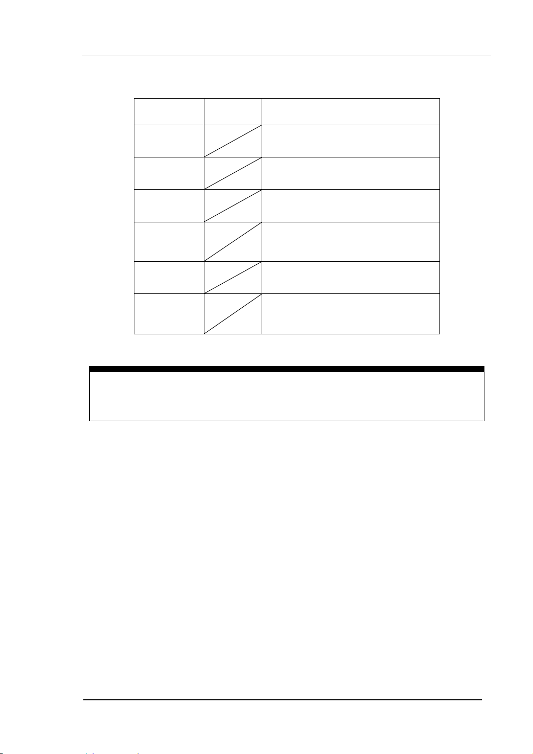
Table 2-13 The Menu Explanations of Waveform Edition
Function
Menu
Settings Explanation
Point# Select the point to be edited
Time Set time for the Selected point
Voltage
Set Voltage for the Selected point
Insert a new point between the
Insert
defined points. Use the “Time” and
“Voltage” to define the new point.
Remove Remove the current point
Save
Save the created waveform to the
non-Volatile Memory.
Instruction:
The time for the last definable point should be less than the cycle period of the
waveform.
© 2006 RIGOL Technologies, Inc
User’s Guide for DG2000 Series
2-25
Page 52

RIGOL
Save the Waveform to the Non-Volatile Memory
Press Arb Æ Edit Æ Creat Æ EditPt Æ Save , enter the following interface.
Select the desired waveform document to be saved, which will be displayed in inverse
color and press Save to save it to the specific place.
Figure 2-36 The Operation Menu
Table 2-14 The Menu Explanations of Saving New Waveform
Function
Menu
Settings Explanation
Local
Disk
U Disk
(When a U
Select display path for the
system information
disk is
connected )
Setting of the Generator
Arbitrary waveform file
All types of documentation
Type
State
Data
All
Recall the waveform or Setting
Recall
information in the specific
position in the memory.
Store
Remove
Save the waveform to the
appointed position
Remove any waveform that
has been stored in the memory
2-26
User’s Guide for DG2000 Series
© 2006 RIGOL Technologies, Inc
Page 53

RIGOL
Instruction
To save the Arbitrary Waveform:
In the Non-volatile Memory, each waveform storage position can only save one
waveform. If a new one is stored, the old one will be erased.
z For a waveform containing points below 128K, the current position will be
used.
z For a waveform containing points from128K to 256K, two sequential position
will be used.
z For a waveform containing points from256K to 512K, All the 4 position will be
used.
In the Graph Mode, the waveform is shown in figure 2-37.
The Default
Arbitrary
Wavefor
m
Figure 2-37 The Waveform Parameter in the Graph Mode
© 2006 RIGOL Technologies, Inc
User’s Guide for DG2000 Series
2-27
Page 54
RIGOL
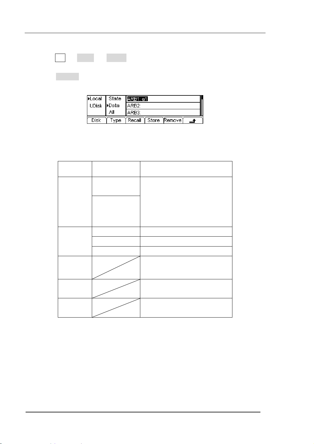
2. To Edit the Stored Waveform
Press Arb Æ Edit Æ Store , enter the following interface. Select the desired
waveform document to be edited, which will be displayed in inverse color and
press Recall to recall and edit it in the Volatile memory.
Figure 2-38 The Operation Menu
Table 2-15 The Menu Explanations of Editing Stored Waveform
Function
Menu
Settings
Explanation
Local
Disk
U Disk
(When a U
Select display path for the
system information
disk is
connected )
Setting of the Generator
Arbitrary waveform file
All types of documentation
Type
State
Data
All
Recall the waveform or Setting
Recall
information in the specific
position in the memory.
Store
Remove
Save the waveform to the
appointed position.
Remove any waveform that
has been stored in the memory
2-28
User’s Guide for DG2000 Series
© 2006 RIGOL Technologies, Inc
Page 55

RIGOL
3. To Delete a Waveform
Press Arb Æ Edit Æ Delete , to delete a waveform. Select the desired
waveform to be deleted which will be displayed in inverse color and press
Remove to delete it.
Instruction
The Ultrawave software can be used to edit the user-defined waveform, and you
can download it from the official website
www.rigolna.com.
© 2006 RIGOL Technologies, Inc
User’s Guide for DG2000 Series
2-29
Page 56
RIGOL
To Generate the Modulated Waveform
Use the Mod button to generate modulated waveform. DG2000 Series can generate
AM, FM, FSK, PM or PWM modulated waveforms. The modulation parameters should
be set in different types of modulation. For example, in AM, users can set the Source
(Internal/ External), depth, Modulating Frequency, Modulating Waveform and Carrier
Waveform; in FM, users can set the Source (Internal/ External), Frequency Deviation,
Modulating Waveform and Carrier Waveform; in FSK, users can set the Source
(Internal/ External), Hop Frequency, FSK Rate, Modulating Waveform and Carrier
Waveform; while in PM, users can set the Source (Internal/ External), Phase Deviation,
Modulating Frequency, Modulating Waveform and Carrier Waveform, etc.
We will explain how to set these parameters in details according to different types of
Modulation.
Figure 2-39 The setting Interface of Modulated Waveform
2-30
User’s Guide for DG2000 Series
© 2006 RIGOL Technologies, Inc
Page 57

RIGOL
AM
The modulated waveform consists of two parts: the Carrier Waveform and the
Modulating Waveform. In AM, the Amplitude of the Carrier Waveform varies with the
instantaneous voltage of the modulating waveform. The Parameters for the AM are
shown in table 2-16.
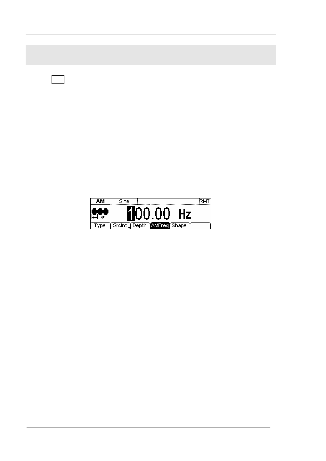
Figure 2-40 The Setting Interface of AM Waveform
Press Mod Æ Type Æ AM , enter the following interface.
Figure 2-41 The Operation Menu
Table 2-16 The Menu Explanations of the AM Parameters
Function
Menu
Settings
Explanation
Type AM Amplitude Modulation
Internal The Source is Internal
SrcInt
SrcExt
External
The Source is External. Use the
[Modulation In] connector in the Rear
panel.
Depth Set the amplitude range
Set the modulating waveform
AMFreq
frequency. Frequency Range:
2mHz~20kHz (Only Internal).
Sine
Square
Waveform
Triangle
UpRamp
DnRamp
Press the function key Sine , Square
etc to choose different Shape of
waveform.
Noise
Arb
© 2006 RIGOL Technologies, Inc
User’s Guide for DG2000 Series
2-31
Page 58

RIGOL
Note: When choose the external modulation, the menu Depth , AMFreq and
Shape will hide.
In the Graph Mode, the waveform is shown in figure 2-42.
Type
Frequency
Depth
Wavefor
Source
Modulated
Carrier
Figure 2-42 The Waveform Parameter in the Graph Mode
Term Explanation
Modulation Depth
The Amplitude Range (also called “Percentage Modulation”). Modulation Depth
varies from 0% to 120%.
z In the 0% Modulation, the output amplitude is the half of the set one.
z In the 100% Modulation, the output amplitude is the same with the set one.
z For an external source, the depth of AM is controlled by the voltage level of the
connector connected to the [Modulation In]. +5V corresponds to the currently
set depth 100%.
2-32
User’s Guide for DG2000 Series
© 2006 RIGOL Technologies, Inc
Page 59

RIGOL
FM
The modulated waveform consists of two parts: the Carrier Waveform and the
Modulating Waveform. In FM, the Frequency of the Carrier Waveform varies with the
instantaneous voltage of the modulating waveform. The Parameters for the FM are
shown in figure 2-43.
Figure 2-43 The Setting Interface of FM Waveform
Press Mod Æ Type Æ FM , enter the following interface.
Figure 2-44 The Operation Menu
© 2006 RIGOL Technologies, Inc
User’s Guide for DG2000 Series
2-33
Page 60
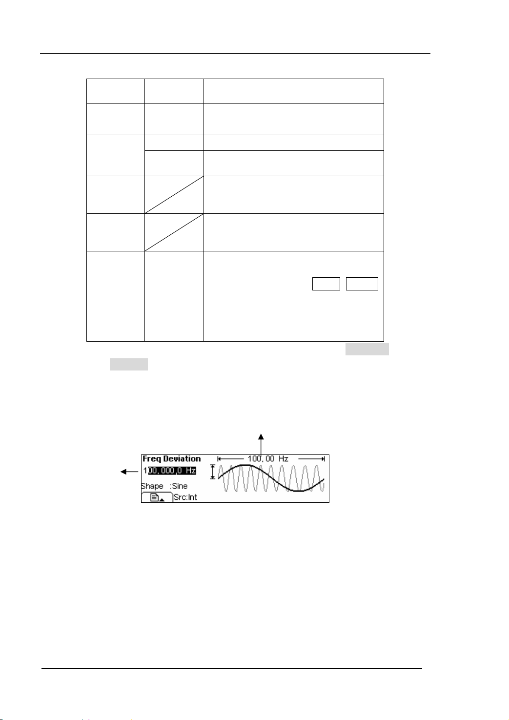
Table 2-17 The Menu Explanations of the FM Parameters
RIGOL
Function
Menu
Settings
Explanation
Type FM Frequency Modulation
SrcInt
SrcExt
Internal Choose the Internal source.
external
Use the rear [Modulation In] linker to
select the external source.
Set the Frequency Deviation between
Deviat.
the Modulating Waveform and the
Carrier Waveform.
Set the modulating waveform
FMFreq
frequency. Frequency Range:
2mHz~20kHz (Only Internal).
Sine
Square
Shape
Triangle
UpRamp
DnRamp
Press the function key Sine , Square
etc to choose different Shape of
waveform.
Noise
Arb
Note: When choose the external modulation, the menu FMFreq
and Shape will hide.
In the Graph Mode, the waveform is shown in figure 2-45.
Modulating
Frequency
2-34
Frequency
Deviation
Figure 2-45 The Waveform Parameter in the Graph Mode
User’s Guide for DG2000 Series
© 2006 RIGOL Technologies, Inc
Page 61

RIGOL
Term Explanation
Frequency Deviation
z The Deviation should be equal to or less than the Carrier Waveform Frequency.
z The Sum of the Deviation and the Carrier Frequency should be equal to or less
than maximum frequency of the selected function plus 100 kHz.
z For an External Source, the Deviation is controlled by the ±5V voltage Level of
the Connector connected to the [Modulation In]. +5V adds to the selected
Deviation, lower external voltage generates less deviation, while negative
voltage reduces the modulated signal frequency below the corresponding
carrier’s.
© 2006 RIGOL Technologies, Inc
User’s Guide for DG2000 Series
2-35
Page 62

RIGOL
FSK
The FSK Modulation is a modulation method, the output frequency shifts between the
two pre-set frequencies (Carrier Waveform Frequency and the Hop Frequency). The
Frequency for the Output Frequency to shift from the carrier waveform frequency to
and from the Hop frequency is called the FSK rate. The frequency by which the output
frequency shift from each other is determined by the Internal Frequency generator or
the Signal Voltage Level offered by the [Ext Trig/FSk/Burst] connector in the rear
panel:
z If you choose the Internal Modulation, the frequency at which the output
frequency shifts between the carrier frequency and the Hop frequency is
determined by the set FSK rate.
z If you choose External Modulation and overlook the FSK rate, the output frequency
is determined by the Voltage Level of the [Ext Trig/FSk/Burst] connector on the
rear panel. If the Voltage Level is low, then generate the carrier frequency; when
the voltage level is High, generate the Hop frequency.
Figure 2-46 The Setting Interface of FSK Waveform
Press Mod Æ Type Æ FSK , enter the following interface.
Figure 2-47 The Operation Menu
2-36
User’s Guide for DG2000 Series
© 2006 RIGOL Technologies, Inc
Page 63

Table 2-18 The Menu Explanations of the FSK Parameters
RIGOL
Function
Menu
Type FSK Frequency Shift Keying Modulation
SrcInt
SrcExt
HopFreq
FSK Rate
Note: When choose the external modulation, the menu FSkRate
will hide.
In the Graph Mode, the waveform is shown in figure 2-48.
Settings
Internal Choose the Internal source.
Use the rear [Ext Trig/FSk/Burst]
external
connector to choose the external
source.
Set the Hop Frequency Range:
1µHz~40MHz.
Set the frequency at which the output
frequency shifts between the carrier
frequency and the Hop frequency
(OnlyInternal): 2mHz~100kHz.
FSK Frequency
Explanation
Hop Frequency
Figure 2-48 The Waveform Parameter in the Graph Mode
© 2006 RIGOL Technologies, Inc
User’s Guide for DG2000 Series
2-37
Page 64

RIGOL
PM
The modulated waveform consists of two parts: the Carrier Waveform and the
Modulating Waveform. In PM, the Phase of the Carrier Waveform varies with the
instantaneous voltage Level of the modulating waveform. The Parameters for the PM
are as shown in figure 2-49.
Figure 2-49 The Setting Interface of PM Waveform
Press Mod Æ Type Æ PM , enter the following interface.
Figure 2-50 The Operation Menu
2-38
User’s Guide for DG2000 Series
© 2006 RIGOL Technologies, Inc
Page 65

Table 2-19 The Menu Explanations of the PM Parameters
RIGOL
Function
Menu
Settings Explanation
Type PM Phase Modulation
Internal Choose the Internal source.
SrcInt
SrcExt
external
Use the rear [Modulation In]
connector to choose the external
source.
Set the Phase Deviation between the
Deviat.
Modulating Waveform and the Carrier
Waveform, ranging from 0
o
to 360o
Set the modulating waveform
Freq
frequency. Frequency Range:
2mHz~20kHz (Only Internal).
Sine
Square
Shape
Triangle
UpRamp
DnRamp
Press the function key Sine, Square
etc to choose different Shape of
waveform.
Noise
Arb
Note: When choose the external modulation, the menu PMFreq
and Shape will hide.
In the Graph Mode, the waveform is shown in figure 2-51.
Modulating
Frequency
Phase
Deviation
Figure 2-51 The Waveform Parameter in the Graph Mode
© 2006 RIGOL Technologies, Inc
User’s Guide for DG2000 Series
2-39
Page 66

RIGOL
PWM
The modulated wave is composed of the carried wave and the modulation wave. In the
PWM ( Pulse-Width Modulation), the pulse width of the carried wave varies with the
instantaneous voltage Level of the modulating waveform. The Parameters for the PWM
are shown in figure 2-52.
Figure 2-52 The Setting Interface of the PWM Waveform
The PWM function is only for modulating the Pulse wave. Once in the other wave
interface, press Mod you may discover the softkey PWM can not be used while
choosing the modulation type, it can enter the PWM interface only by pressing Mod
Once in the Pulse interface.
Press Pulse and enter the PWM interface, then press Mod, enter the following menu.
2-40
Figure 2-53 The operation menu
© 2006 RIGOL Technologies, Inc
User’s Guide for DG2000 Series
Page 67

RIGOL
T
T
Table 2-20 The Menu Explanations of the PWM Parameters
Function
Menu
Settings Explanation
Type PWM Pulse Width Modulation
Internal Choose the Internal source.
SrcInt
SrcExt
external
Use the rear [Modulation In]
connector to choose the external
source.
DtyDev
WidDev
Set the offset of the PWM.
Set the frequency of the modulation
PWMFreq
wave with the range: 2mHz~20kHz
(Only Internal).
Sine
Square
Shape
Triangle
UpRamp
DnRamp
Press the function key Sine, Square
etc to choose different Shape of
waveform.
Noise
Arb
Note: When choose the external modulation, the menu WMFreq
and Shape will hide.
In the Graph Mode, the waveform is shown in figure 2-54.
he frequency of phase
modulation
he offset of
the phase
Figure 2-54 The Waveform Parameter in the Graph Mode
Instructions:
z The max range of DtyDev is the minimum in (duty, 1 - duty);
The max range of WidDev is the minimum in (width, period - width).
z
© 2006 RIGOL Technologies, Inc
User’s Guide for DG2000 Series
2-41
Page 68
RIGOL
To Generate Sweep
In the frequency sweep mode, the function generator “sweep” from the start
frequency to the stop frequency at the sweep rate you specify. Sweeping can be
generated by Sine, Square, Ramp or Arbitrary Waveforms (Pulse, Noise and DC are not
allowed).
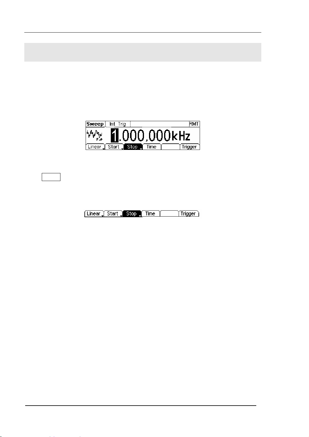
Figure 2-55 The Setting Interface of Sweep Waveform
Press Sweep button, in the Normal Mode, the operation menu will appear on the
bottom of the screen, see figure 2-56. Set the Waveform parameters by using the
operation menu.
Figure 2-56 The Operation Menu
2-42
User’s Guide for DG2000 Series
© 2006 RIGOL Technologies, Inc
Page 69
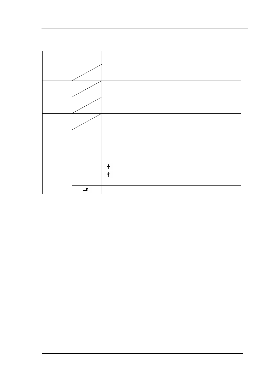
Table 2-21 The Menu Explanations of the Sweep Parameters
RIGOL
Function
Menu
Linear/
log
Start/
Center
Stop
Span
Time
Trigger
Settings Explanation
Set the Sweep frequency with linear change
Set the Sweep frequency with logarithmic change
Set the Start Frequency of the Sweep
Set the Center Frequency of the Sweep
Set the Stop Frequency of the Sweep
Set the Frequency Span of the Sweep
Set the Time Span of the Sweep for which the Frequency
changes from the Start Frequency to Stop Frequency.
Int: Choose Internal Source
Ext: Choose External Source, use the [Ext
Source
Trig/FSk/Burst] connector in the rear panel
Manual: Choose External Source, set the start and stop
time by hand
: Signal Triggered at Rise Edge
Trig Ou t
: Signal Triggered at Fall Edge
Off: Turn off Trigger Setting
Finish Setting
© 2006 RIGOL Technologies, Inc
User’s Guide for DG2000 Series
2-43
Page 70
RIGOL
Sweep Frequency Setting
Use Start and Stop or Center and Span to set the range of the frequency.
Press the button again to switch to each other.
z To Sweep upward, set the Start Frequency lower than the Stop Frequency, or set a
positive frequency interval.
z To Sweep downward, set the Start Frequency higher than the Stop Frequency, or
set a negative frequency interval.
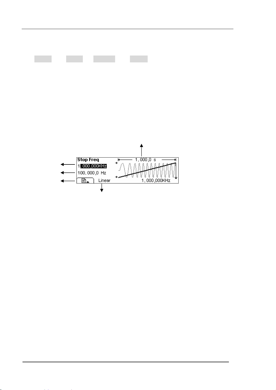
In the Graph Mode, the waveform is shown in figure 2-57.
Sweep Time
Stop Frequency
Start Frequency
Sweep Type
Figure 2-57 The Waveform Parameter in the Graph Mode
2-44
User’s Guide for DG2000 Series
© 2006 RIGOL Technologies, Inc
Page 71
RIGOL
To Generate Burst
Burst Function can generate versatile waveforms in burst, which can last specific times
of waveform cycle(N-Cycle Burst), or when the external gated signals( Gated Burst) is
applied, any waveform could be used. But noise can only be used in Gated Burst.
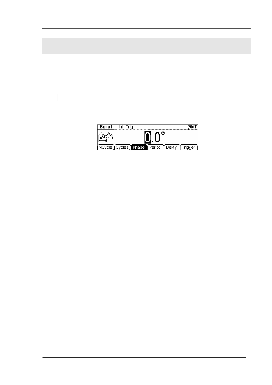
Press Burst button, in the Normal Mode, the operation menu will appear on the bottom
of the screen, see figure 2-58. Set the Waveform parameters by using the operation
menu.
Figure 2-58 The Setting Interface of Burst Waveform
© 2006 RIGOL Technologies, Inc
User’s Guide for DG2000 Series
2-45
Page 72

Set the N-Cycle Burst
Press Burst Æ NCycle , enter the following menu.
Figure 2-59 The Operation Menu
Table 2-22 The Menu Explanations of N-Cycle Burst
RIGOL
Function
Menu
Settings Explanation
N-Cycle Set the N-Cycle Mode
Cycles/
Infinite
Set the Number of the bursts in a N-Cycle
Set the Number of the bursts in a N-Cycle
to be infinite
Phase Set the Start Phase of the Burst
Period Set the Period of the Burst
Delay Set the Delay of the burst
Int: Choose Internal Source
Ext: Choose External Source, use the [ Ext
Source
Trig/FSk/Burst] connector in the rear
panel
Manual: Choose External Source, set the
Trig ge r
start and stop time by hand
: Signal Triggered at Rising Edge
Trig Ou t
: Signal Triggered at Falling Edge
Off: Turn off Trigger Setting
Finish Setting
2-46
User’s Guide for DG2000 Series
© 2006 RIGOL Technologies, Inc
Page 73
RIGOL
N-Cycle/ Gated
N-Cycle has specific number of waveform cycles, and every burst is activated by a
trigger event. Gated burst controls burst by external source.
Cycle Number
Set the number of Waveform Cycle in an N-Cycle (1 to 1,000,000 or Infinite).
If you choose Infinite, then a continuous waveform will be generate which will not stop
until a trigger event happens (Trigger button is pressed).
z If needed, Burst Period will increase to cater to the specific number of cycles.
z For a frequency greater than 25MHz, only a bust with infinite cycles is allowed.
z For an infinite-cycle Burst, External or Manual Trigger is needed to activate burst.
Phase
Define the Start and the Stop Point in a waveform. The phase varies from -360° to
+360°, and the default setting is 0°. For an Arbitrary Waveform, 0° is the phase of the
first waveform point.
Period
Set the time span between an N-Cycle Burst and the next. If necessary the period will
increase to reach the specific number of cycles in a burst.
Burst Period> Period X Burst Number
Delay
Set the Time Delay between the Trigger Input and the Start of the N-Cycle Burst. The
minimum delay is a function of the specific burst period, and should always be greater
than 0.
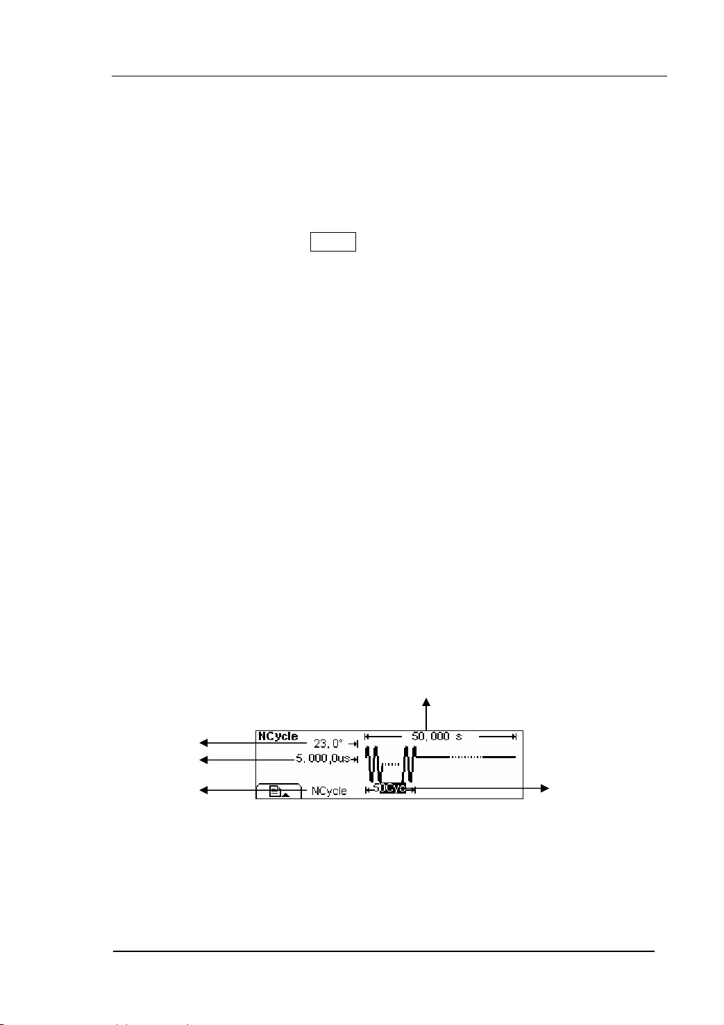
In the Graph Mode, the waveform is shown in figure 2-60.
Burst Period
Start Phase
Delay
N-Cycle
Cycle Times
Figure 2-60 The Waveform Parameter in the Graph Mode
© 2006 RIGOL Technologies, Inc
User’s Guide for DG2000 Series
2-47
Page 74

Set the Gated Burst
Press Burst Æ Gated , enter the following menu.
Figure 2-61 The Operation Menu
Table 2-23 The Menu Explanations of Gated Burst
RIGOL
Function
Menu
Settings Explanation
Gated Set the Gated Mode
Polarity
Phase
Pos
Neg
Set the Polarity of the Gated Signal
Set the Start Phase of the Gated
Signal
In the Graph Mode, the waveform is shown in figure 2-62.
Start Phase
Positive Gated Signal
Gated
Figure 2-62 The Waveform Parameter in the Graph Mode
2-48
User’s Guide for DG2000 Series
© 2006 RIGOL Technologies, Inc
Page 75

RIGOL
To Store and Recall
Press Store/Recall button, and the operation menu will appear at the bottom of the
screen. You can save or read the State or Data Documentation in the Generator or
build and delete documentation in the U Disk. File names can either be Chinese or
English.
Figure 2-63 The Save and Read Interface
Figure 2-64 The Operation Menu
Table 2-24 The Menu Explanations of Store and Recall
Function
Menu
Settings Explanation
Local
Disk
U Disk
Choose display route for the
system information
(When U Disk is
connected )
Setting of the Generator
Arbitrary waveform file
All types of documentation
Type
State
Data
All
Recall the waveform or Setting
Recall
information in the specific
position in the memory.
Store
Remove
Save the waveform to the
appointed position.
Remove any waveform that
has been stored in the memory
About the Disk
Use the Disk button to choose Local or U Disk (When U Disk is connected).
© 2006 RIGOL Technologies, Inc
User’s Guide for DG2000 Series
2-49
Page 76

RIGOL
To Save the Instrument State
Users are allowed to store the instrument state in any one of the 4 Non-Volatile
Memories. When the power is on again, the instrument will return to the state before it
was powered off. The state storage will “memorize” the selected function (including
the Arbitrary Waveform), Frequency, Amplitude, DC Offset, Duty Cycle, Symmetry,
and other modulation parameters used.
To Save the Instrument State, following the steps:
1. Choose the file Type to store
Press Store/Recall Æ State , and set the storage type as “State”.
2. Choose the location of the file.
There are four positions in the local STATE1, STATE2, STATE3 and STATE4, and
you can choose one of them by rotating the knob.
3. Name the file and Save it
Press Store button, enter the self-defined name. Press Store to finish.
2-50
User’s Guide for DG2000 Series
© 2006 RIGOL Technologies, Inc
Page 77

RIGOL
To Save Data
Users are allowed to store data document in any of the 4 Non-Volatile Memories. If the
position is already occupied, the new document will cover the old one. To save the
data, following the steps:
1. Set the file Type to store
Press Store/Recall Æ State Æ data , and choose “data” as the storage type.
2. Choose the location of the file.
There are four positions in the local ARB1, ARB2, ARB3 and ARB4, and you can
choose one of them by rotating the knob.
3. Name the file and Save it
Press Store button, enter the self-defined name. Press Store to finish.
© 2006 RIGOL Technologies, Inc
User’s Guide for DG2000 Series
2-51
Page 78

RIGOL
The interconnection of DG2000 and DS1000
We have introduced the interfaces of DG2000 to you before, and mentioned the USB
Host Interface. And now, we will introduce how to use this interface to connect
DG2000 with DS1000 (oscilloscope) to realize the nondestructive data Transmission.
1. Connect DG2000 with DS1000 to sample data;
2. Connect the USB Host Interface of DG2000 with the USB Device Interface of
DS1000. View the waveform in DS1000, following the steps below:
View the Acquired Waveform
Press Store/Recall button, enter the following menu.
Figure 2-65 The operation menu
Rotate the knob, choose CH2: ON
Figure 2-66 Choose the channal
The pre-setting for data reading is finished, and we are going to view the waveform
DS1000 acquired.
Press Read , and DG2000 will store the waveform that DS1000 acquired in the
Volatile Memory.
2-52
User’s Guide for DG2000 Series
© 2006 RIGOL Technologies, Inc
Page 79

RIGOL
To export the waveform acquired
Press Arb Æ Load Æ Volatile , to load the waveform just read.
Figure 2-67 The operation menu
Figure 2-68 Load the waveform
Notes:The frequency shown in DG2000 may be different greatly from that you
imagine. This is because that DG2000 considers the acquired 512K points as a period.
If you want to get the real period of the generated waveform, you have to multiple the
frequency value shown on DG2000 with the number of the real period in this false
period.
Figure 2-69 The Waveform Display in DS1000
As shown in the figure above, this is the waveform shown on another DS1000 by the
above operation. Please note that the frequency shown on this instrument is the same
as the expected one.
© 2006 RIGOL Technologies, Inc
User’s Guide for DG2000 Series
2-53
Page 80
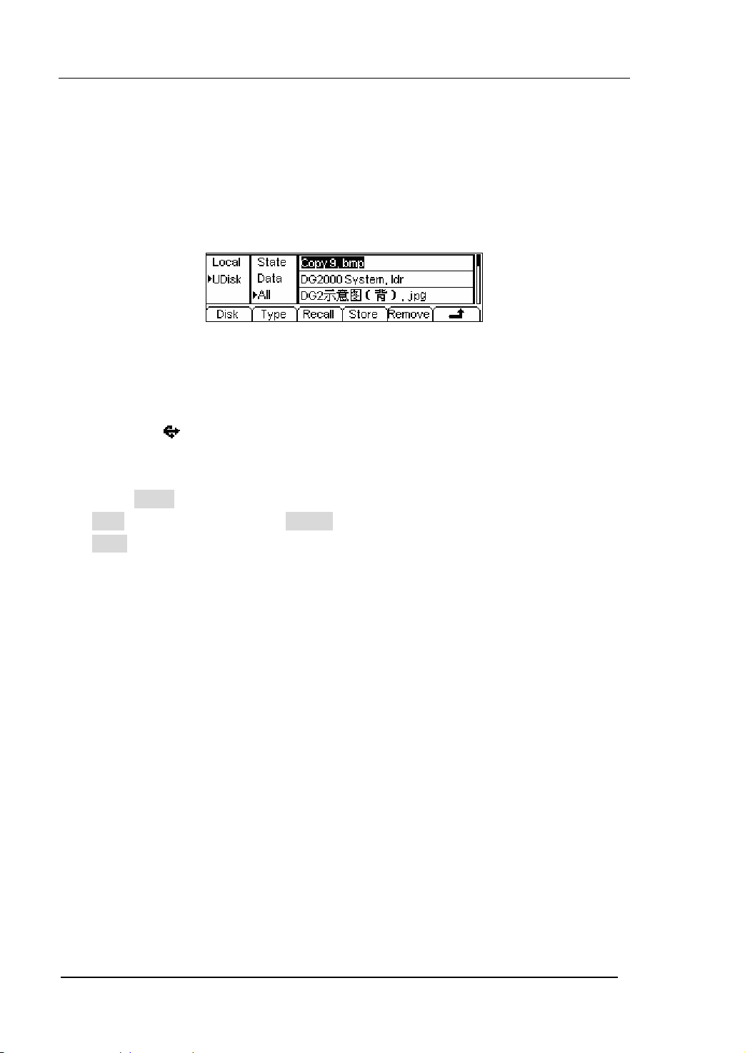
RIGOL
To Use USB storage
As shown in figure 2-70, the storage location is divided into: the inherent storage
(Local) and the U Disk storage(U Disk). At the left side of the front panel, there is a
USB interface. When a USB storage is connected, the storage menu will show “U Disk ”.
The default location is the local storage.
Figure 2-70 The Interface of USB Storage
1. Install the Mobile Storage
Insert the mobile memory to the USB interface on the front panel, and the screen
will show “
2. Choose the Mobile Memory
Press Disk , move the cursor upward or downward to select “U Disk”. Choose
Type to be “data” and press Store , enter the file name and then press
Store to save the file.
3. Uninstall the Mobile Storage
Remove the U Disk from the Interface and the system will inform you that the U
Disk has been removed, and the “U Disk” Sign will disappear.
Note: DG2000 supports the flash U disk in the format of FAT (less than 1G) and FAT32
(less than 2G).
”.
2-54
User’s Guide for DG2000 Series
© 2006 RIGOL Technologies, Inc
Page 81

RIGOL
To Save a File
Press Store/Recall Æ Store , enter the following interface. Enter the self-defined file
name in the “File Name” frame. Below the frame is the input keypad. Use the direction
button to select the desired character. When the character is in inverse color, press
Select to input it.
Figure 2-71 The File Storage Interface
Figure 2-72 The Operation Menu
Table 2-25 The Menu Explanations of File Storage
Function
Menu
Lang
Settings Explanation
EN English Input
CN Chinese Input
Select Select the current character
Remove
Delete the current character
Store Store the file with the current name
Cancel the current operation
© 2006 RIGOL Technologies, Inc
User’s Guide for DG2000 Series
2-55
Page 82

RIGOL
1. English Input
The English Input Interface is shown in figure 2-73, to save a file named as
“NewFile”, following the steps below:
File Name
Input
Keypad
Figure 2-73 The English Input Interface
(1) Press Lang Æ EN , enter the English Interface;
(2) Input the file name” NewFile”.
Use the Knob to adjust the cursor to the right character, and press Select .
Repeat this until you have selected all the characters needed. Press +/- to
choose the majuscule or lowercase.
(3) Edit the File Name
When you have entered a wrong character, move the cursor to the wrong
character and press Remove to delete it. And then reenter the file name.
(4) Press Store , to finish and save the file.
2-56
User’s Guide for DG2000 Series
© 2006 RIGOL Technologies, Inc
Page 83

RIGOL
2. Chinese Input
The Chinese Input Interface is shown in figure 2-74. To save a new file, follow the
steps below:
File Name Input
Input menu
Page Controller
Key Pad
Figure 2-74 The Chinese Input Interface
(1) Press Lang Æ CN , enter the Chinese Input Interface.
(2) Press “ +/- ”to choose the lowercase, and input the spell of the Chinese.
(3) Input the file name : “新文件”
Use the Knob to adjust the cursor to the right character, and press Select ,
input “Xin”. In the Input Menu, choose the Chinese character you need with
the help of the page controller and the 1~9 button on the keypad.
(4) Edit the wrongly input
When a file name is wrong, move the cursor to the character and press
Remove to delete it and reenter the file name.
(5) Press Store to finish and save the file.
Notes: The length of file name user can edit is up to 25 characters or 11 Chinese
characters (The file can be stored in U-disk or non- volatile memories, but the length of
file name has the limit). The length limit in non-volatile memories is 12 characters or 6
Chinese characters; the limit in U-disk is 39 characters or 19 Chinese characters.
If surpass the length limit, N/A is shown.
© 2006 RIGOL Technologies, Inc
User’s Guide for DG2000 Series
2-57
Page 84
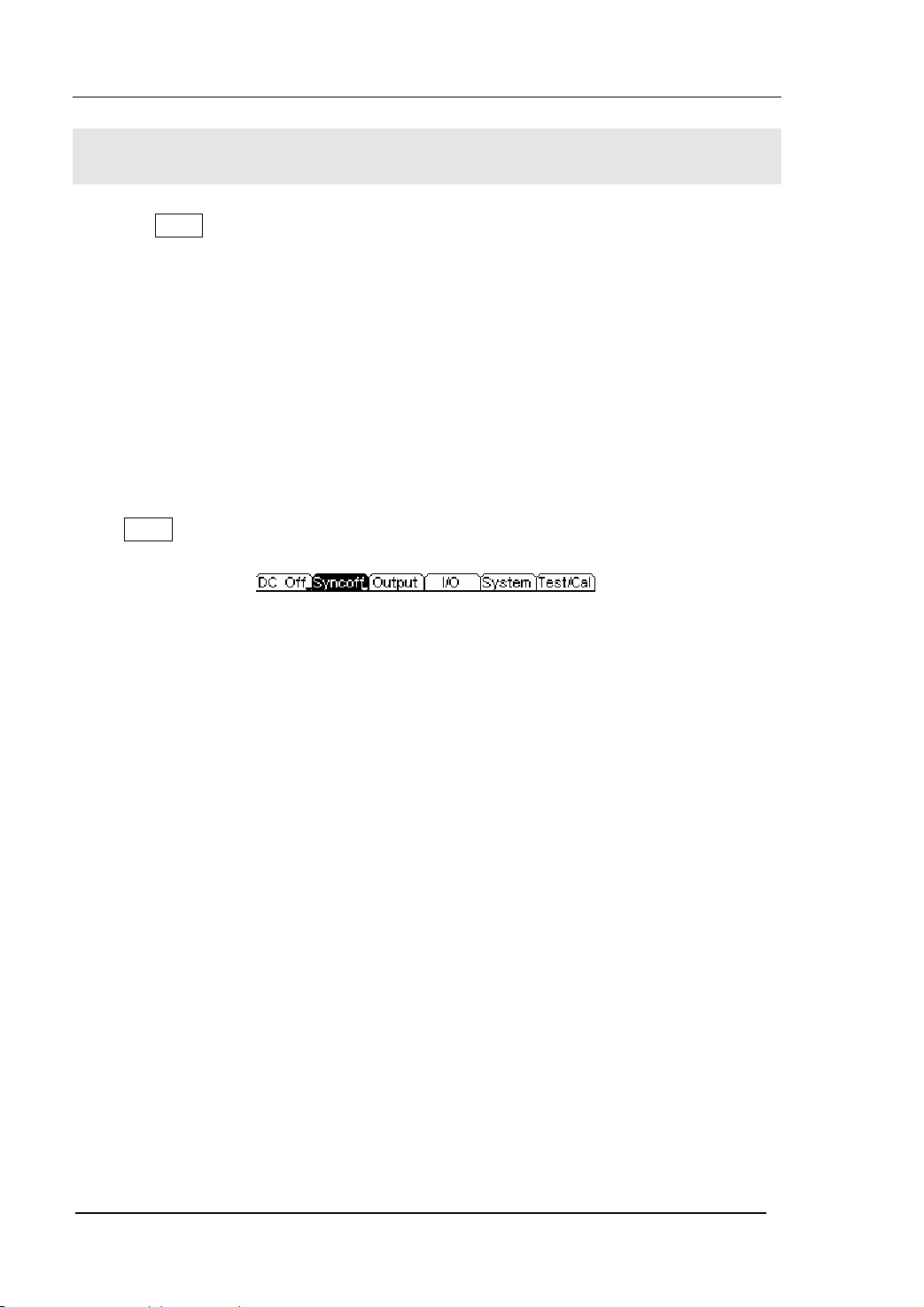
RIGOL
To Set the Utility Function
With the Utility function, you can set the parameters of the Generator such as: DC
On/Off, Sync On/Off, Output Parameter, Interface Parameter, System Setting and
Testing Parameter. The DC switch offers the options of DC output or Arbitrary
Waveform Output. Sync Switch offers the option to choose the Sync Signal or not. The
Output setting provides the parameter setting for Load/Impedance, Range, Normal/
Inverse and Phase. The Interface Setting offers the storage and load of the configure
parameter setting for GPIB (IEEE-488), LAN, RS232 or USB remote control. The
System Setting provides the setting for Language, Display, Beep, Screen Guard,
Format, Power System Configure and default setting. The test setting provides the
self-testing and calibration storage as well as the password and safety switch.
Press Utility to enter the Utility Menu. Its functions are listed below in table 2-26.
Figure 2-75 The Operation Menu
2-58
User’s Guide for DG2000 Series
© 2006 RIGOL Technologies, Inc
Page 85

Table 2-26 The Menu Expanations of Utility System Setting
RIGOL
Function
Menu
DC On/
Off
Sync On/
Off
Settings Explanation
On Set the output waveform as DC
Off Set the output waveform as Arbitrary.
On
Off
Activate the Sync Signal of the [Sync]
Connector on the front panel.
Deactivate the Sync Signal of the [Sync]
Connector on the front panel.
Output Set the Output parameter (Table 2-27)
I/O Set the I/O (Table 2-28)
System Set the System Configuration (Table 2-33)
Tes t/ Ca l
Test and Calibrate the instrument (Table
2-37)
Instruction
Sync Switch Setting:
When the amplitude is low relatively, you can reduce the distortion of the output
signal by prohibiting the Sync Signal. And the current storage is in the Non-Volatile
Memory.
© 2006 RIGOL Technologies, Inc
User’s Guide for DG2000 Series
2-59
Page 86
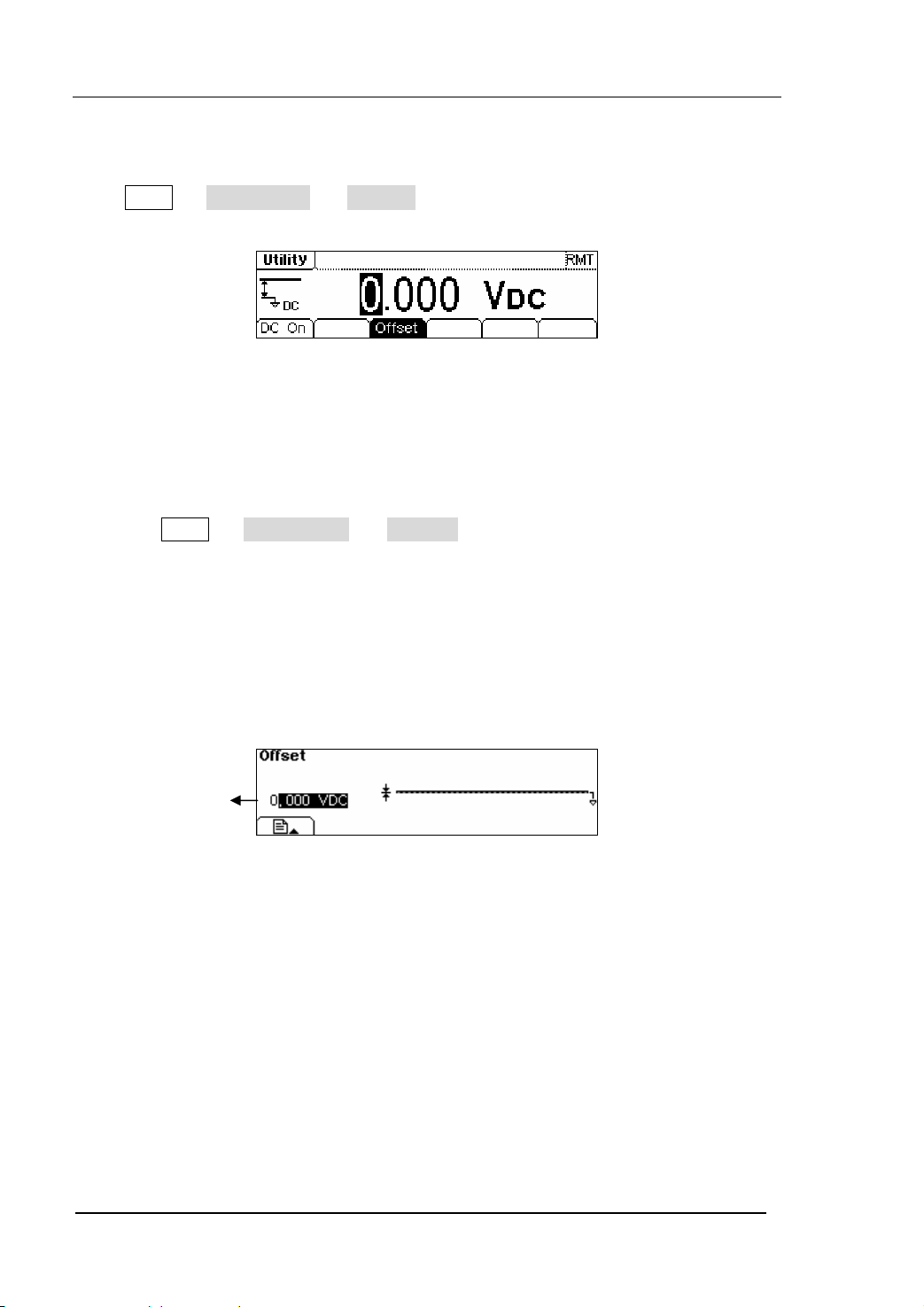
RIGOL
To Set the DC Output
Press Utility Æ DC On/Off Æ DC On , enter the following interface.
Figure 2-76 The DC Setting Interface
DC Offset
Set the DC Voltage Level.
To Shift into the Arbitrary Waveform Output
(1) Press Utility Æ DC On/Off Æ DC Off , close the DC output and return the
output of the Arbitrary Waveform.
(2) Press any functional button, and the waveform output setting turns to the output
of arbitrary waveform. The DC option is turned off automatically.
In the Graph Mode, the waveform is shown in figure 2-77.
2-60
Offset
Figure 2-77 Waveform Parameter in the Graph Mode
© 2006 RIGOL Technologies, Inc
User’s Guide for DG2000 Series
Page 87

RIGOL
To Set the Sync Output
The Generator provides Sync output through the [Sync] Connector on the Front Panel.
All the standard output functions (except DC and Noise) have a corresponding Sync
Signal. For some Sync applications, they can be prohibited if users do not want to use
them.
z In the default setting, the Sync Signal should be connected to the [Sync]
Connector (activated). When the Sync Signal is prohibited, the output voltage
Level of the [Sync] Connector is Low.
z In the Inverse Mode, the Sync Signal does not Inverse.
z For Sine, Square, Ramp and Pulse Signal, the Sync Signal is a Square Signal with
50% Duty Cycle. When the output is positive, the Sync Signal is TTL High Level
compared to 0 V Voltage or DC Offset; when the output is negative, The Sync
Signal is TTL Low Level compared to 0 V Voltage or DC Offset.
z For Arbitrary Waveform, the Sync Signal is a Square Waveform with 50% Duty
Cycle. At the time when the first output waveform point is generated, the Sync
Signal Voltage is TTL High Level.
z For AM, FM and PM in Internal Modulation, the Sync Signal reference is the
Modulated Signal (not the Carrier Signal). The Sync Signal is a Square Waveform
with 50% Duty Cycle. In the first half modulation period, the Sync Signal is TTL
High Level. For External Modulation, the Sync Signal reference is the Carrier Signal
(not the Modulated Signal). The Sync Signal is also a Square Waveform with 50%
Duty Cycle.
z For FSK, the Sync Signal Reference is the Hop Frequency, and the Sync Signal is a
Square Waveform with 50% Duty Cycle. For the Hop Frequency, at the hopping
point, the Sync Signal is TTL High Level.
z For the Burst, when the burst starts, the Sync Signal is High Level. At the specific
point when the Cycle Number ends, the Sync Signal turns Low Level (If the
Waveform has a relative starting phase, it may be not zero intersections). For an
infinite burst, the Sync Signal is the same as the Sync Signal of the continuous
Signal.
© 2006 RIGOL Technologies, Inc
User’s Guide for DG2000 Series
2-61
Page 88

RIGOL
z For the External Gated Burst, the Sync Signal follows the External Gated Signal.
But, please note that this signal will not turn Level Low until the last period end (If
the Waveform has a relative starting phase, it may be not zero intersections).
2-62
User’s Guide for DG2000 Series
© 2006 RIGOL Technologies, Inc
Page 89

To Set Output Parameter
Press Utility Æ Output , enter the following menu.
Figure 2-78 The Operation Menu
Table 2-27 The Menu Explanations of Output Setting
RIGOL
Function
Menu
Settings Explanation
Set the Load connected to the Output
Load
High Z
Connector.
Set the Load connected to the Output
Connector as High Z.
Range
Normal
Inverse
Phase
Allow the Instrument to choose the best
Amplifier/ Attenuator
Waveform Normal Output
Waveform Inverse Output
Set the Phase Offset of the Output
Waveform
© 2006 RIGOL Technologies, Inc
User’s Guide for DG2000 Series
2-63
Page 90

RIGOL
1. To Set the Output Load
For the [Output] Connector on the Front panel, the Generator has a built-in 50Ω
series output impedance. If the actual load does not match the set one, the
amplitude and offset displayed are incorrect. This function is used to match the
displayed voltage with the expected one.
Steps for setting the Load value:
(1) Press Utility Æ Output Æ Load , enter the following interface.
Please note that the Load Parameter shown on the right bottom is the default
when the power is on or the pre-set load value. If the current value is valid for
the output, then the current value can be used.
(2) Input the desired Load Value.
Use the Keypad or the Knob to enter the desired value and choose the unit: Ω
or KΩ, press the corresponding button.
Figure 2-79 Set the Output Load
Instruction
DG2000 Series have a fixed 50Ω Series impedance no matter what the value has
set for this parameter.
If the real load is different from the set one, the displayed voltage will not equal
with the real voltage.
2-64
User’s Guide for DG2000 Series
© 2006 RIGOL Technologies, Inc
Page 91
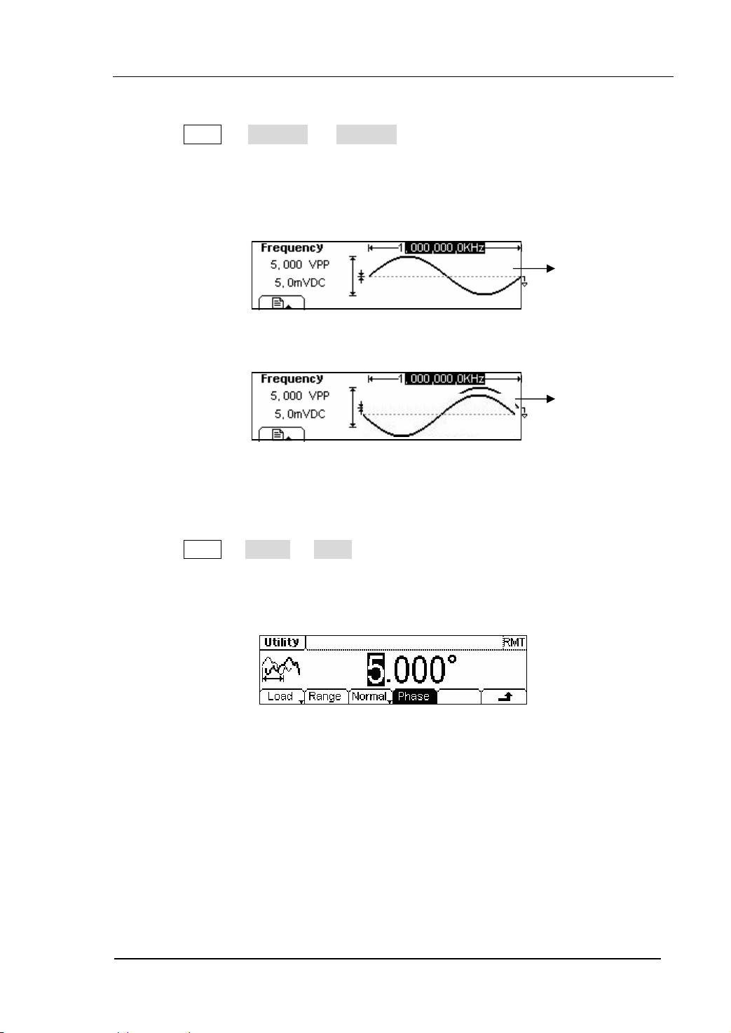
RIGOL
2. To Set the Inverse Waveform
Press Utility Æ Output Æ Inverse , to set the inverse Waveform output.
No offset voltage will change while the waveform is inversed. An inversed
waveform will be displayed in the Graph Mode.
Normal
Figure 2-80 The Normal Waveform
Inverse
Figure 2-81 The Inverse Waveform
3. To Adjust the Phase
Press Utility Æ Output Æ Phase, enter the following interface.
Set the Phase with the unit of degree.
Figure 2-82 Set the Phase
© 2006 RIGOL Technologies, Inc
User’s Guide for DG2000 Series
2-65
Page 92
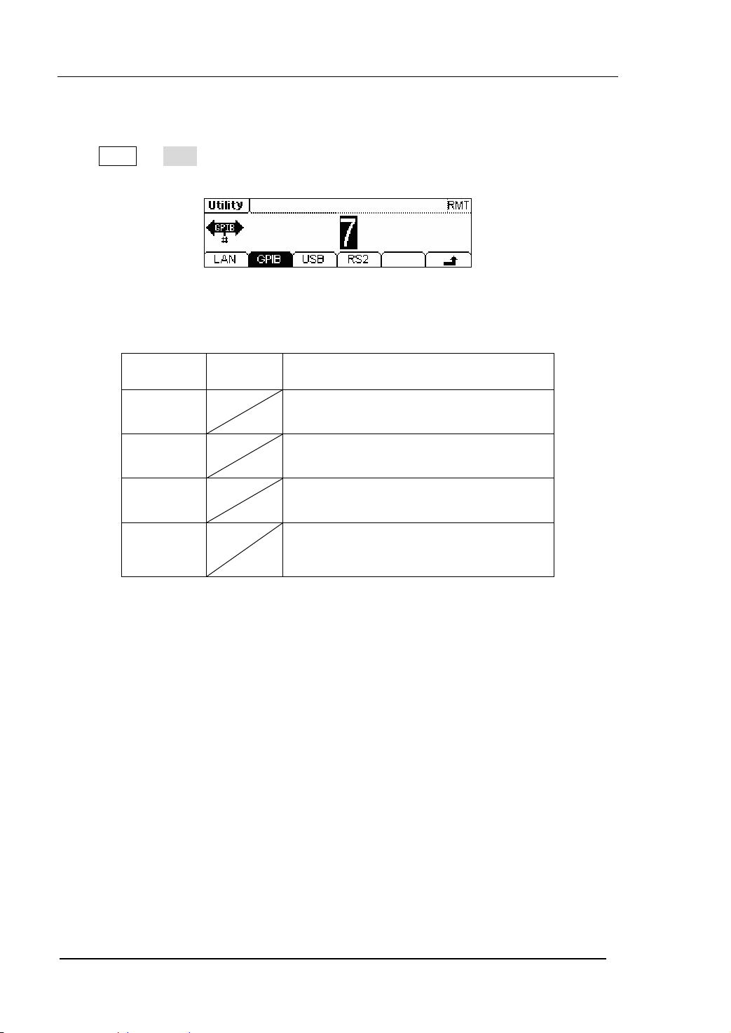
To Set the I/O
Press Utility Æ I/O , to set the I/O. See figure 2-83.
Figure 2-83 The Setting Interface of the I/O
Table 2-28 The Menu Explanations of Setting I/O
RIGOL
Function
Menu
Settings Explanation
LAN Set the LAN configuration parameter
GPIB Set the GPIB Address
USB See USB equipment address
RS232
Set the RS232 Interface
Set the GPIB address as any value within 0 ~ 30. The default setting is “7”. The
Address is stored in the Non-Volatile Memory, and will show when the power is on.
The I/O Setting offers the Storage and Load of the configuration parameter setting of
the GPIB(IEEE-488), RS232 or LAN which are used for remote control.
2-66
User’s Guide for DG2000 Series
© 2006 RIGOL Technologies, Inc
Page 93

RIGOL
1. To Set LAN
You can configure the IP Address, the DNS setting or check the current network
configuration by setting the LAN interface.
Press Utility Æ I/O Æ LAN , enter the following interface.
Figure 2-84 The Operation Menu
Table 2-29 The Menu Explanations of LAN Setting
Function
Menu
IP
setup
Settings Explanation
Set the corresponding parameter for IP
DNS Set the corresponding parameter for DNS
Info The current setting information about the host
IP Setup
Press Utility Æ I/O Æ LAN Æ IPSetup , enter the following interface.
Figure 2-85 The Interface of IP Setup
© 2006 RIGOL Technologies, Inc
User’s Guide for DG2000 Series
2-67
Page 94

Table 2-30 The Menu Explanations of IP Setup
RIGOL
Function
Menu
DHCP
On/Off
IP
addr
Settings Explanation
On
Off
Open the DHCP setting, allot the IP
address dynamically
Close the DHCP setting, set the IP
address manually
Set the IP address
IP Mask Set the IP Mask
Gate Way Set the Gate Way
Instruction
Open the DHCP:
Press DHCPon , allot the IP address dynamically. At this time, the IPAddr ,
IPmask and Gate way menu will hide.
DNS
Press Utility Æ I/O Æ LAN Æ DNS , enter the following interface.
2-68
Figure 2-86 The Setting Interface of DNS
Table 2-31 The Menu Explanations of Setting DNS
© 2006 RIGOL Technologies, Inc
User’s Guide for DG2000 Series
Page 95

RIGOL
Function
Menu
Settings Explanation
Host Set the Host Name
Domain Set the Domain
Server Set the Server Address
Host Name
Set the Host Name, it consists of letter, number and dash (“-”). Consult with your
network administrator for the Host name you need. Use the knob and the direction
button to select the character to set the host name (you can only use the keypad to
enter the number). The Host name will be stored in the Non-Volatile Memory.
Domain Name
Set the Domain Name with letter, number, dash (“-”) and dot (“.”). Consult with your
network administrator for the Domain name you need. Use the knob and direction
button to select the character to set the domain name (you can only use the keypad to
enter the number and dot). The Domain name will be stored in the Non-Volatile
Memory.
Info
Press Utility Æ I/O Æ LAN Æ Info , the current system information is shown
below.
Figure 2-87 The System Information
Instruction
If the DHCP is enabled and you want to use the DNS address that the DHCP
Server returns, please set the Server to be “0.0.0.0”.
2. To Set GPIB
© 2006 RIGOL Technologies, Inc
User’s Guide for DG2000 Series
2-69
Page 96

The range of the GPIB interface address is 0~30, and the default value is “7”.
Press Utility Æ I/O Æ GPIB , enter the interface below.
Figure 2-88 The Interface of Setting the GPIB
RIGOL
3. To Set RS232
2-70
User’s Guide for DG2000 Series
© 2006 RIGOL Technologies, Inc
Page 97
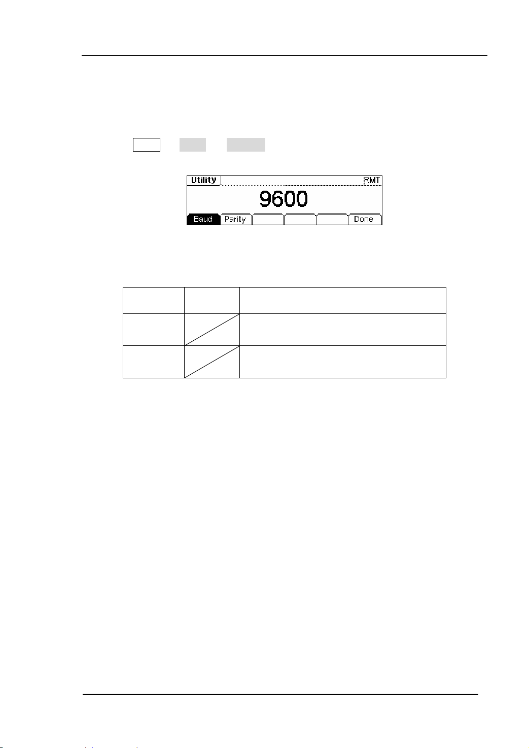
RIGOL
Make sure that the Baud Rate and the Parity match the computer. Besides, make
sure that the RS232 cable is connected correctly. The I/O setting is stored in the
Non-Volatile Memory, and will show when the power is on.
Press Utility Æ I/O Æ RS232 , enter the following interface.
Figure 2-89 The Setting Interface of Setting RS232
Table 2-32 The Menu Explanations of Setting RS232
Function
Menu
Baud Set the RS232 Baud Rate
Parity Set the RS232 Parity and the data digit
Baud Rate
Set the RS232 Baud Rate. Make sure that the Baud Rate matches the computer. The
optional rates are: 115k, 57.6k, 38.4k, 19.2k, 9600, 4800, 2400, 1200. The default
setting is 9600. The current setting is stored in the Non-Volatile Memory.
Parity
Set the Parity and the data digit of RS232. Make sure that the parity matches the
computer. The optional settings are: Odd, Even and No Parity. The default setting is
“No Parity”. The current setting is stored in the Non-Volatile Memory.
Settings Explanation
To Set the System
© 2006 RIGOL Technologies, Inc
User’s Guide for DG2000 Series
2-71
Page 98
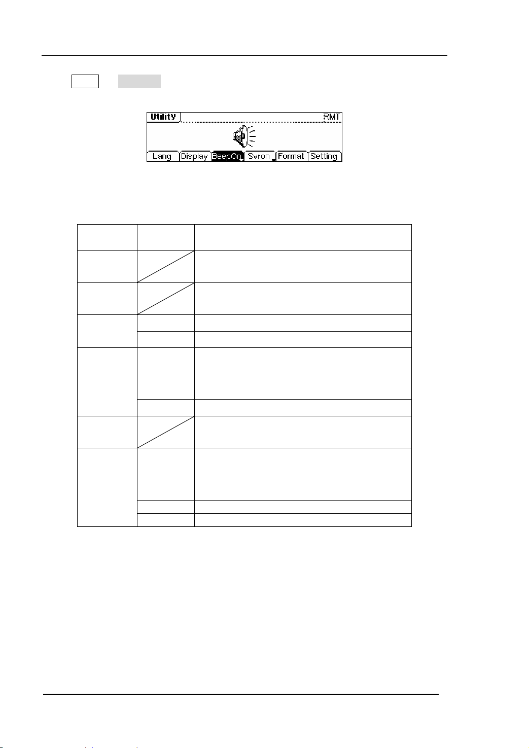
Press Utility Æ System , enter the following interface.
Figure 2-90 The Operation Menu
Table 2-33 The Menu Explanations of System Setting
RIGOL
Function
Menu
Lang Set the System Language
Display Set the parameter for the Screen Display
Beep
On/Off
Svr on/off
Format Set the data format
Setting
Key points:
Power On
2-72
Settings Explanation
On Open Beeper
Off Close Beeper
Activate the Screen Guard function. Screen
On
Guard will be on if no action is taken within
3 minutes. Press any button to return the
display screen.
Off deactivate the Screen Guard function
PowOn: When the power is on, all the
PowOn
setting will return to the default value.
Latest: When the power is on, all the setting
will return to the latest setting.
Default Return all the setting into the default
Timer Choose the clock source as internal/external
© 2006 RIGOL Technologies, Inc
User’s Guide for DG2000 Series
Page 99

RIGOL
The Setting is used when the instrument is powering on.
Two choices are available: the default setting and the latest. Once selected, the setting
will be used when the instrument restarts.
Beep
Activate or deactivate the sound when an error occurs from the front panel operation
or the remote interface operation. Activate or deactivate any sound made by the
button or knob on the front panel.
© 2006 RIGOL Technologies, Inc
User’s Guide for DG2000 Series
2-73
Page 100

1. Language Setting
The DG2000 Series Generator supports two languages: Chinese and English.
To Select Language, press Utility and then Lang to select the language.
Press Utility Æ System Æ Lang , change the current language.
Figure 2-91 The Interface of Language Setting
2. Display Control
Press Utility Æ System Æ Display , enter the following interface.
RIGOL
Figure 2-92 The Interface of Display Setting
Table 2-34 The Menu Explanations of Display Setting
Function
Menu
Settings Explanation
Contra Set the Display Contrast Parameter
Light Set the Display Light Parameter
Invert Set the Invert Display
2-74
User’s Guide for DG2000 Series
© 2006 RIGOL Technologies, Inc
 Loading...