

Page 1

User’s Guide RIGOL
Publication number DG1-070518
May 2007
DG1000 Series Function/Arbitrary
Waveform Generator
© Copyright RIGOL Technologies, Inc. 2007
All Rights Reserved
Page 2

Page 3

RIGOL
z Copyright © RIGOL TECHNOLOGIES, INC. 2007 All Rights Reserved.
z RIGOL products are protected by patent law in and outside of P.R. China.
z Information in this publication replaces all the corresponding materials
published previously.
z RIGOL Technologies, Inc. reserves the right to modify or change part of or all
the specifications and pricing policies at company’s sole decision.
NOTE: RIGOL is the registered trademark of RIGOL TECHNOLOGIES, INC.
© Copyright RIGOL Technologies, Inc. 2007
User’s Guide for DG1000 Series
I
Page 4

RIGOL
Safety Notices
Review the following safety precautions carefully before operating the instrument to
avoid any personal injury or damage to the instrument or products connected to it.
To avoid potential hazards, use the instrument in the manner specified in this user’s
guide.
The instrument should be serviced only by qualified personnel.
To Avoid Fire or Personal Injury
Use proper power line. Only the special power line of the products approved by
the State should be used.
Insert or draw properly. Do not insert draw when the probe and the testing lead
are connected with the power.
Ground the instrument. This generator is grounded through the protective terra
conductor of the power cord. To avoid electric shock, the grounding conductor must
be connected to the earth ground. Make sure that the instrument is properly
grounded before connecting the input or output terminals.
Connect the probe properly. Connect the output terminal of the signal properly,
make sure that the potential difference between the output terminal of the signal’s
terra line and the earth is lower than 40V DC.
The probes’ ground terminals are at the same voltage level with the earth terminal of
the instrument. Do not connect the ground terminals to a high voltage.
Observe All the Ratings of the Terminal. To avoid fire or shock, observe all the
ratings and symbols that marked on the instrument. Read the user’s guide carefully
before making connections to the instrument.
Do not operate without Covers. Do not operate your generator without covers or
panels.
II
© Copyright RIGOL Technologies, Inc. 2007
User’s Guide for DG1000 Series
Page 5

RIGOL
Use Proper Fuse. Only use the fuse type and rating specified for this product.
Avoid Circuit or Wire exposed. Do not touch the exposed connections or
components when the power is turn-on.
Do not operate with suspected failures. If you suspect there is damage with
this product, have it inspected by qualified service personnel authorized by RIGOL
before further operations.
Provide Proper Ventilation.
Do not operate in wet/damp conditions.
Do not operate in an explosive atmosphere.
Keep the product’s surfaces clean and dry.
© Copyright RIGOL Technologies, Inc. 2007
User’s Guide for DG1000 Series
III
Page 6
RIGOL
Safety Terms and Symbols
Terms in This Guide. These terms may appear in this manual:
!
!
Terms on the Product. These terms may appear on the product:
DANGER indicates an injury or hazard that may be immediately happen.
WARNING indicates an injury or hazard that may be not immediately happen.
CAUTION indicates that a potential damage to the instrument or other property
might occur.
Symbols on the Product. These symbols may appear on the Instrument:
Hazardous
Voltage
WARNING: Warning statements indicate the conditions or practices that
could result in injury or loss of life.
CAUTION: Caution statements indicate the conditions or practices that
could result in damage to this product or other property.
!
Refer to the
Instructions
Protective
earth terminal
Grounding
Terminal
of Chassis
Test
Grounding
Terminal
IV
© Copyright RIGOL Technologies, Inc. 2007
User’s Guide for DG1000 Series
Page 7

RIGOL
RIGOL DG1000 Generator at a Glance
This guide covers the following two types of DG1000 Series Function/ Arbitrary
Waveform Generators:
DG1021、DG1011
RIGOL DG1000 Series Function/ Arbitrary Waveform Generator adopt the DDS
technology, which can provide stable, high-precision, pure and low distortion sine
signal. It can also provide 5MHz square waveform with fast rising and falling edges.
Its combination of excellent system features, easiness in usage and versatile
functions makes this generator a perfect solution for your job now and in the future.
DG1000 Series Function/ Arbitrary Waveform Generator have clear and simple
Front-Panel. The user-friendly panel layout and instructions, versatile terminals,
direct graph interface, built-in instructions and help system have greatly simplified
the operation process, thus, users do not have to spend a great deal of time learning
and familiarizing the operation of the generator before they can use it proficiently.
The built-in AM, FM, PM and FSK modulating functions generate modulated
waveform at ease, without the help of a separate modulating source. The USB I/O is
the standard accessory.
From the characteristics and specifications given below, you will understand how
DG1000 can satisfy your measurement requirements.
z DDS technology provides precise, stable and low distortion output signal.
z 10 standard waveforms:
Sine, Square, Ramp, Pulse, Noise, Sinc, Exponential Rise, Exponential Fall,
Cardiac and DC.
z 100MSa/s sampling rate, enable to edit arbitrary waveform with 14-bit, 4K
points.
z Frequency characteristics:
Sine: 1µHz to 20 MHz
Square: 1µHz to 5 MHz
Ramp: 1µHz to 150 kHz
Pulse: 500µHz to 3MHz
White Noise:5MHz bandwidth (-3dB)
Arbitrary waveform:1μHz to 5MHz
© Copyright RIGOL Technologies, Inc. 2007
User’s Guide for DG1000 Series
V
Page 8

RIGOL
z Amplitude range:2mVPP to 10VPP (50 Ω)
4mV
PP to 20VPP (High Z)
z Abundant modulation function, various modulated waveform: AM, FM, PM and
FSK.
z Linear, logarithm Sweep and Burst mode.
z Abundant I/O: External Modulation Source, External 10 MHz Reference Input,
External trigger source, waveform output, synchronous digital signal output,
Internal 10 MHz Reference output.
z Support USB storage device. Could store and read waveform configure
parameters or the edited arbitrary waveform with USB devices. System Updating
could also be performed by using USB devices.
z Standard interface: USB Host & Device
z Graph interface which shows the signal setting directly.
z Multilanguage user interface.
z Embedded Chinese/ English Help System.
z Support Chinese/ English Input.
Notice:
All the indexes described in this guide are according to DG1021, if you
need to know the particular specifications about the other type, please
look over “Appendix A” in Chapter 6.
VI
© Copyright RIGOL Technologies, Inc. 2007
User’s Guide for DG1000 Series
Page 9

RIGOL
Content
Safety Notices ......................................................................................................................II
RIGOL DG1000 Generator at a Glance...........................................................................V
Chapter 1 Getting Started...................................................................................... 1-1
General Inspection ........................................................................................................... 1-2
Handle Adjustment........................................................................................................... 1-3
The Front/Rear Panel....................................................................................................... 1-4
The DG1000 User Interface ............................................................................................1-7
To Set a Waveform .......................................................................................................... 1-8
To Set Modulate/ Sweep/Burst..................................................................................... 1-11
To Set Trigger/Output ................................................................................................... 1-13
To Use Digital Input ....................................................................................................... 1-14
To Use Store/Utility/Help Function............................................................................... 1-15
Chapter 2 Operating Your Generator................................................................. 2-1
The Menu/Graph Mode.................................................................................................... 2-2
To Set Sine Signals........................................................................................................... 2-3
To Set Square Signals...................................................................................................... 2-7
To Set Ramp Signals ...................................................................................................... 2-10
To Set Pulse Signals....................................................................................................... 2-12
To Set Noise Signals....................................................................................................... 2-14
To Set Arbitrary Signals................................................................................................. 2-15
To Set Counter................................................................................................................ 2-27
To Generate the Modulated Waveform....................................................................... 2-32
To Generate Sweep........................................................................................................ 2-41
To Generate Burst ..........................................................................................................2-44
To Store and Recall ........................................................................................................ 2-49
To Set the Utility Function............................................................................................. 2-56
How to Use the Built-in Help System........................................................................... 2-74
Chapter 3 Application & Examples ..................................................................... 3-1
Example 1: To Generate a Sine Wave ........................................................................... 3-1
Example 2: To generate a Square Wave ....................................................................... 3-2
Example 3: To generate a Ramp Wave .........................................................................3-3
Example 4: To generate a Pulse Wave ..........................................................................3-4
Example 5: To Generate a Noise Wave ......................................................................... 3-5
© Copyright RIGOL Technologies, Inc. 2007
User’s Guide for DG1000 Series
VII
Page 10

RIGOL
Example 6: To generate Arbitrary Waveform ...............................................................3-6
Example 7: To Generate an Arbitrary Waveform ......................................................... 3-7
Example 8: To Generate an AM Waveform ...................................................................3-9
Example 9: To Generate an FSK Waveform................................................................ 3-11
Example 10: To generate a Linear Sweep Waveform................................................ 3-13
Example 11: To generate a Burst Waveform .............................................................. 3-15
Example 12: To measure the frequency...................................................................... 3-17
Chapter 4 Prompt messages & troubleshooting............................................4-1
Prompting Messages ........................................................................................................4-1
Troubleshooting ..............................................................................................................4-18
Chapter 5 Support & Service................................................................................. 5-1
Chapter 6 Appendix..................................................................................................6-1
Appendix A Specifications................................................................................................6-1
Appendix B DG1000 Series Accessories ........................................................................6-9
Appendix C General Care and Cleaning.......................................................................6-10
VIII
© Copyright RIGOL Technologies, Inc. 2007
User’s Guide for DG1000 Series
Page 11

Chapter 1 Getting Started
This chapter covers the following topics:
General Inspection
To Ad j us t th e Han d le
The Front/rear Panel of DG1000 Series
The User Interface of DG1000 Series
To Se t a Wave f o r m
To Set Modulation/Sweep/Burst
To Set Trigger/Output and Counter
To Use Digital Input
To Use Store/Utility/Help Function
RIGOL
© Copyright RIGOL Technologies, Inc. 2007
User’s Guide for DG1000 Series
1-1
Page 12

RIGOL
General Inspection
When you get a new DG1000 Series Function/ Arbitrary Waveform Generator, you
are suggested to take the following steps to inspect the instrument.
1. Inspect the shipping container for damage.
If there are damages in the packing or foam, keep them until he whole machine
and the accessories passing the electric and mechanical testing.
2. Check the accessories.
Accessories supplied with the instrument are listed in chapter 6"Appendix B:
DG1000 Series Accessories". If the contents are incomplete or damaged, please
contract the local selling representative of RIGOL.
3. Inspect the instrument.
In case any mechanical damage or defect, or if the instrument does not operate
properly or pass performance tests, notify your RIGOL Sales Representative.
If the shipping container is damaged, or the cushioning materials show signs of
stress, notify the carrier of your RIGOL sales office. Keep the shipping materials
for the carrier’s inspection. RIGOL offices will arrange for repair or replacement
at RIGOL’s option without waiting for claim settlement.
1-2
© Copyright RIGOL Technologies, Inc. 2007
User’s Guide for DG1000 Series
Page 13
RIGOL
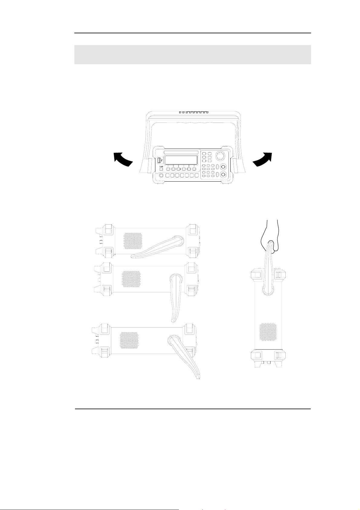
Handle Adjustment
To adjust the handle position of DG1000 Function/ Arbitrary Waveform Generator,
please grip the handle by the sides and pull it outward. Then, make the handle rotate
to the desired position. The operating methods are shown below in graphs 1-1 and
1-2.
Figure 1-1 The method of adjusting the handle
Figure 1-2 Adjustable Positions
© Copyright RIGOL Technologies, Inc. 2007
User’s Guide for DG1000 Series
1-3
Page 14
RIGOL
The Front/Rear Panel
When you get a new DG1000 Series Function/ Arbitrary Waveform Generator, first
you need to know how to operate the front/ Rear panel correctly. This chapter will
make a brief introduction and description for the operation and functions of the
Front/ Rear Panel.
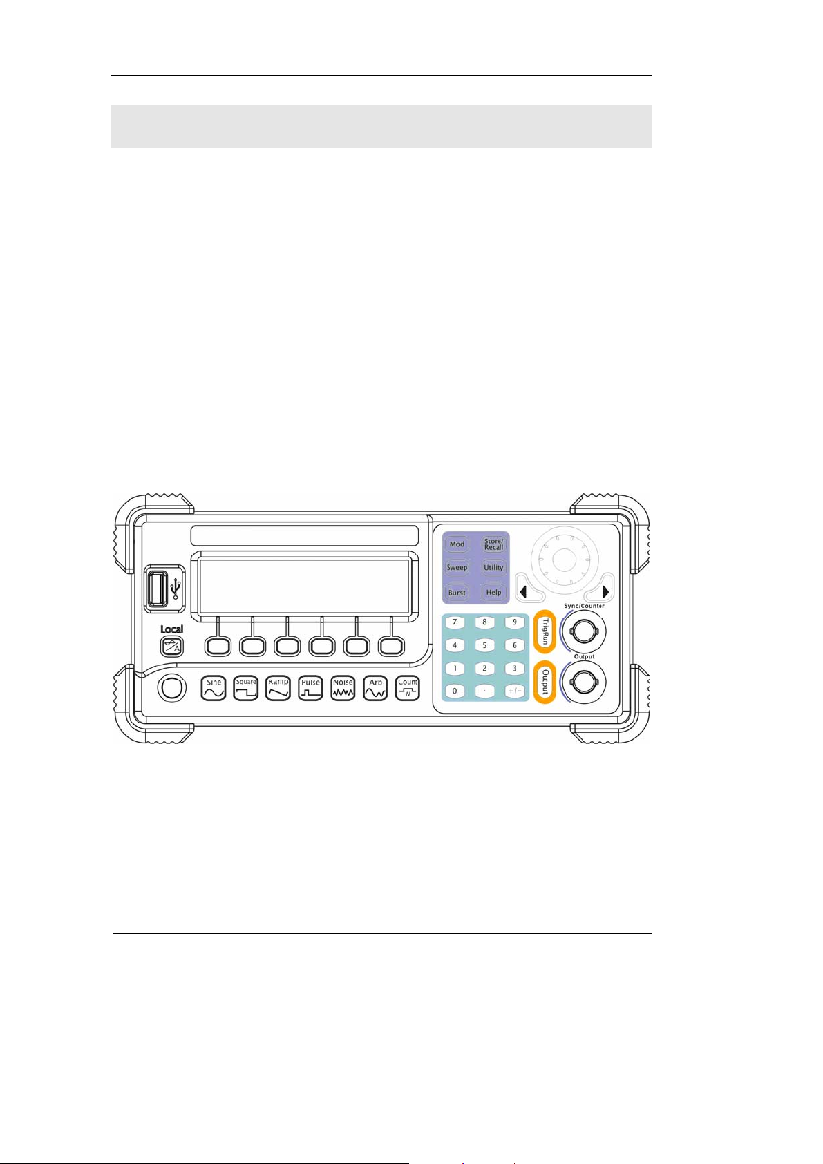
The Front Panel at a Glance
DG1000 Series Function/ Arbitrary Waveform Generator has clear and simple front
panel. See Figure 1-3 and Figure 1-4. The Front Panel has a knob, functional keys
and menu buttons. The 6 grey buttons below the screen are menu buttons, by using
which you can choose different options on the current menu. The rests are the
functional keys, with which you can enter different function menus or obtain specific
functional applications directly.
Figure 1-3
Front Panel for DG1000 Series
1-4
© Copyright RIGOL Technologies, Inc. 2007
User’s Guide for DG1000 Series
Page 15
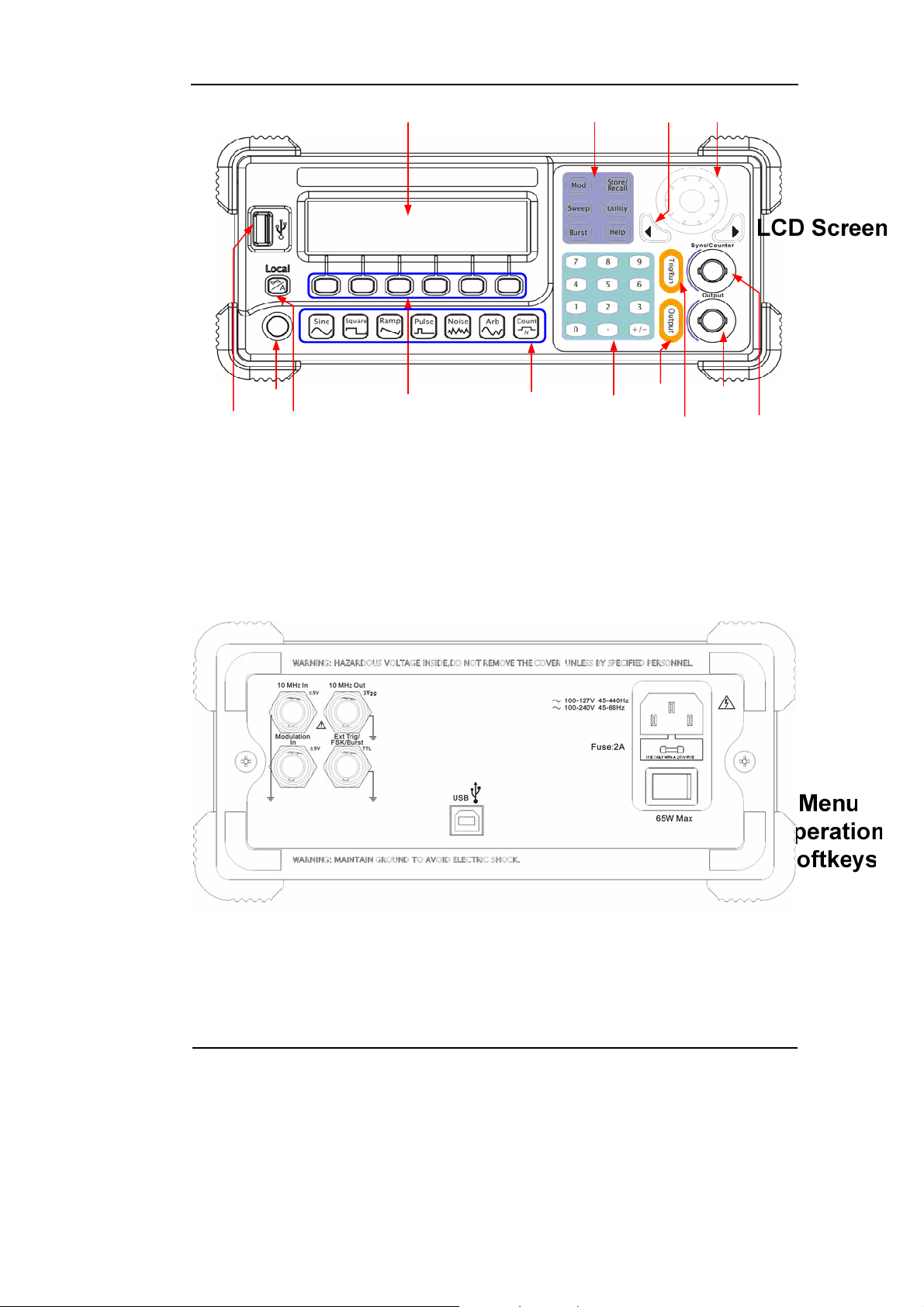
Front Panel Operation Instruction for DG1000 Series
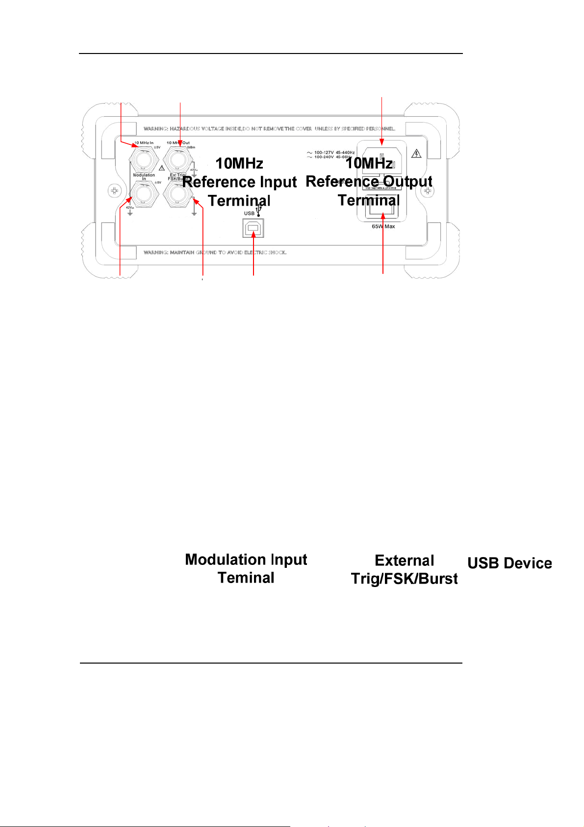
The Rear Panel at a Glance
RIGOL
Figure 1-4
Figure 1-5
Rear Panel for DG1000 Series
© Copyright RIGOL Technologies, Inc. 2007
User’s Guide for DG1000 Series
1-5
Page 16
RIGOL
Figure 1-6
Rear Panel Operation Instruction for DG1000 Series
1-6
© Copyright RIGOL Technologies, Inc. 2007
User’s Guide for DG1000 Series
Page 17

RIGOL
The DG1000 User Interface
DG1000 Series Function/ Arbitrary Waveform Generator provide two Display modes:
Menu and Graph. Under the Menu Display mode, the display interface is divided into
4 parts: state, waveform icon, operation menu, and parameter display. See Figure
1-7. Under the Graph display mode, you can check the current waveform parameters
in the graphics. The display interface is also divided into 4 parts: state, parameter
display, display menu button and waveform display. See Figure 1-8. The operation
menu will appear at the bottom of the screen when you press any menu button.
These two display modes can be switched to each other by pressing the /A
button.
State
Waveform
Operation
Menu
Parameter
Figure 1-7
The menu Display Mode Interface Instruction
Parameters
Display Menu
button
State
Parameter
Display
Waveform
Display
Figure 1-8
Graph Mode Display Interface Instruction
Note:
The signs for the buttons in this guide are the same as the panel buttons. Please note
that the signs for the functional buttons on the operation panel are represented by
squared words, such as Sine, which represents the transparent functional key with
Sine on it on the front panel, while the menu buttons are represented by shadow
words such as Freq, which means the “Frequency” option in the Sine menu.
© Copyright RIGOL Technologies, Inc. 2007
User’s Guide for DG1000 Series
1-7
Page 18
RIGOL
To Set a Waveform
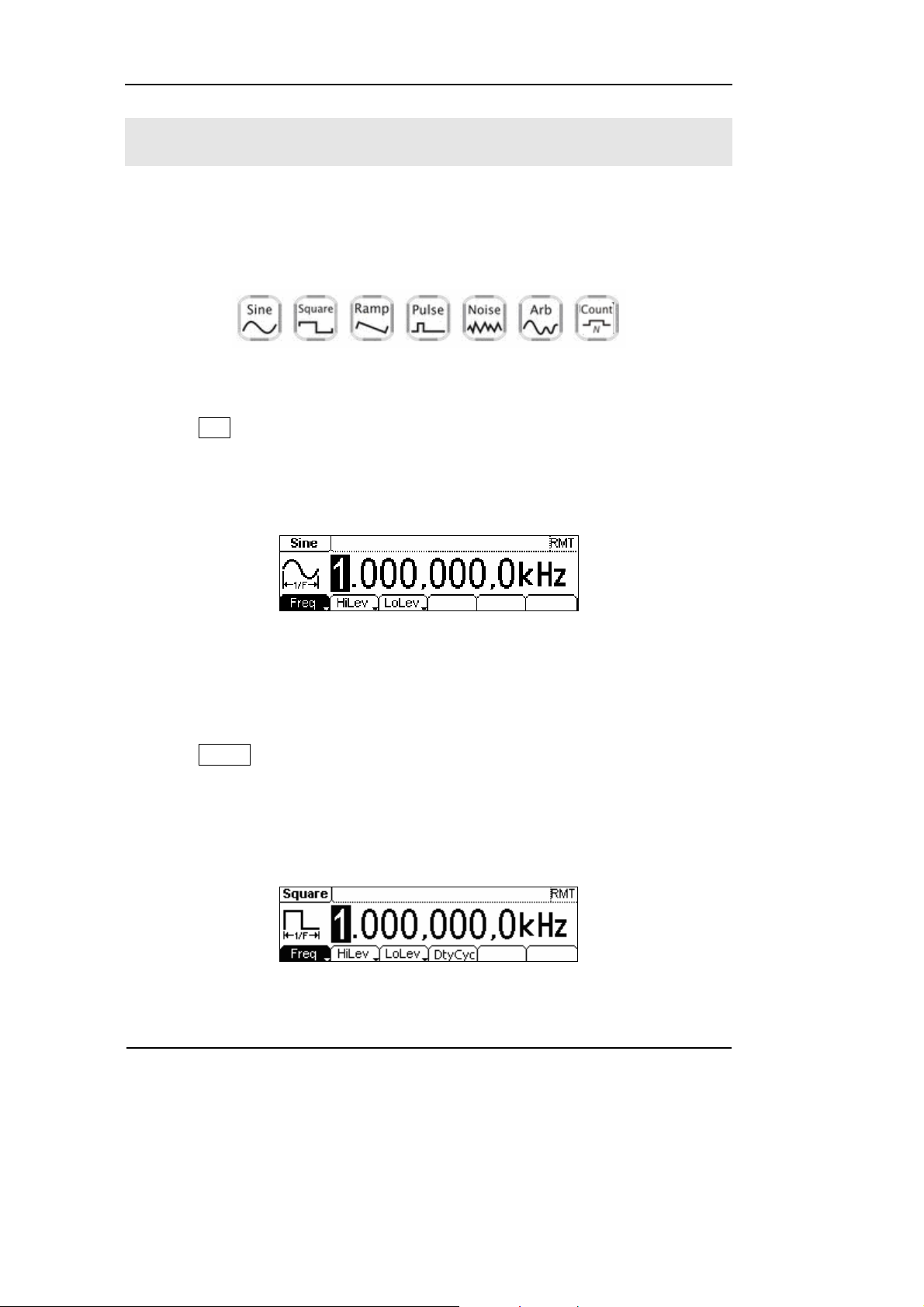
At the left of the operation panel, there is a set of buttons with waveform icon. See
Figure 1-9. The exercise below will help you to be familiar with the waveform
selection settings. The instructions of the waveform setting are all carried out in the
Menu Display Mode.
Figure 1-9
Waveform Selection Buttons
1. Press Sine button, and the waveform icon turns into Sine with a “Sine” typeface
in the state area. DG1000 Series Generator can generate Sine signal with
frequency from 1μHz to 20MHz. By setting Frequency/Period, Amplitude/ High
Level, Offset/ Low level, sine signal with different parameters can be generated.
Figure 1-10
Sine Signal in the Menu Display Mode
As shown in Figure 1-10, the default signal parameters are: 1kHz Frequency, 5.0 V
Amplitude and 0 V
DC Offset.
PP
2. Press Square button, and the waveform icon turns into Square with a “Square”
typeface in the state area. DG1000 Series Generator can generate Square signal
with frequency from 1μHz to 5MHz and variable duty cycle. By setting
Frequency/Period, Amplitude/ High Level, Offset/ Low level, and Duty Cycle,
Square signal with different parameters can be generated.
Figure 1-11
Square Signal in the Menu Display Mode
1-8
© Copyright RIGOL Technologies, Inc. 2007
User’s Guide for DG1000 Series
Page 19
RIGOL
As shown in Figure 1-11, the default signal parameters are: 1kHz Frequency, 5.0 V
PP
Amplitude, 0 VDC Offset and 50% Duty Cycle.
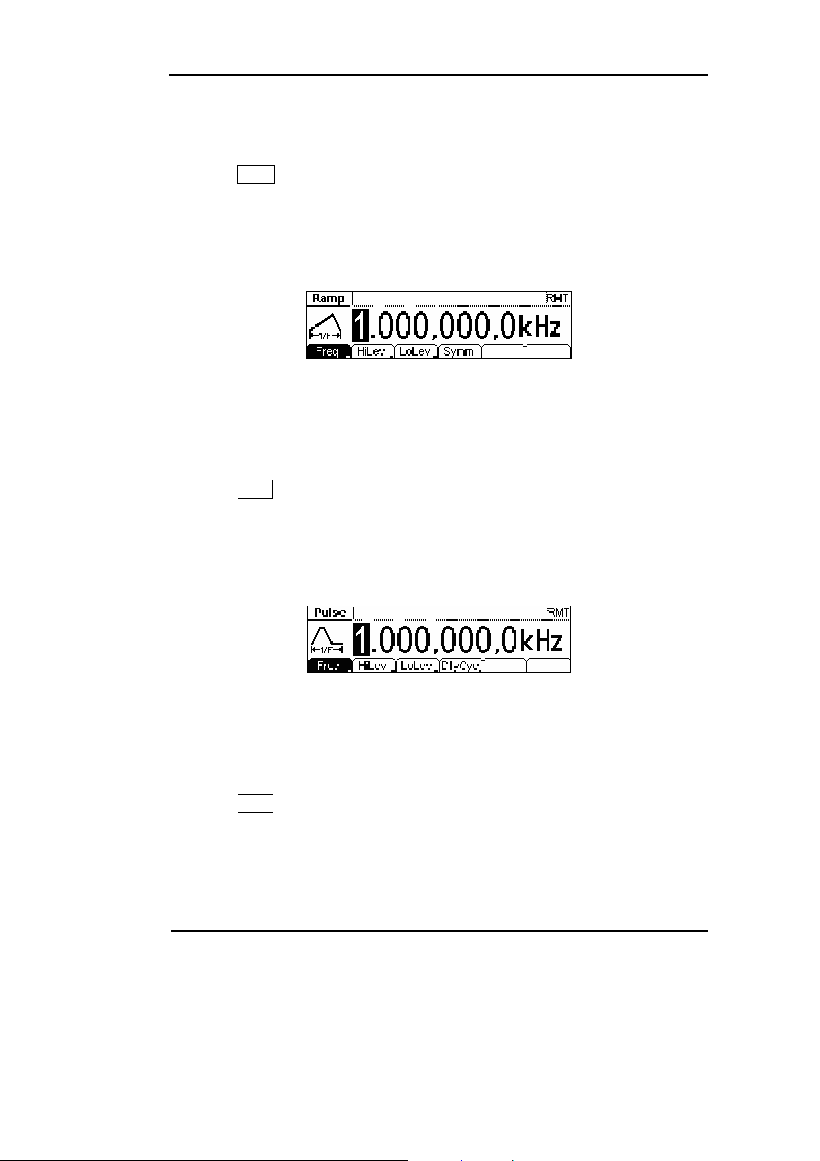
3. Press Ramp button, and the waveform icon turns into Ramp with a “Ramp”
typeface in the state area. DG1000 Series Generator can generate Ramp signal
with frequency from 1μHz to 150 kHz and variable Symmetry. By setting
Frequency/Period, Amplitude/ High Level, Offset/ Low level, and Symmetry,
Ramp signal with different parameters can be generated.
Figure 1-12
Ramp Signal in the Menu Display Mode
As shown in Figure 1-12, the default signal parameters are: 1kHz Frequency, 5.0 V
PP
Amplitude, 0 VDC Offset and 50% Symmetry.
4. Press Pulse button, and the waveform icon turns into Pulse with a “Pulse”
typeface in the state area. DG1000 Series Generator can generate Pulse signal
with frequency from 500μHz to 3MHz and variable Pulse Width. By setting
Frequency/Period, Amplitude/ High Level, Offset/ Low level, Pulse Width and
Duty Cycle, Pulse signal with different parameters can be generated.
Figure 1-13
Pulse Signal in the Menu Display Mode
As shown in Figure 1-13, the default signal parameters are: 1kHz Frequency, 5.0 V
PP
Amplitude, 0 VDC Offset, 200μs Pulse Width.
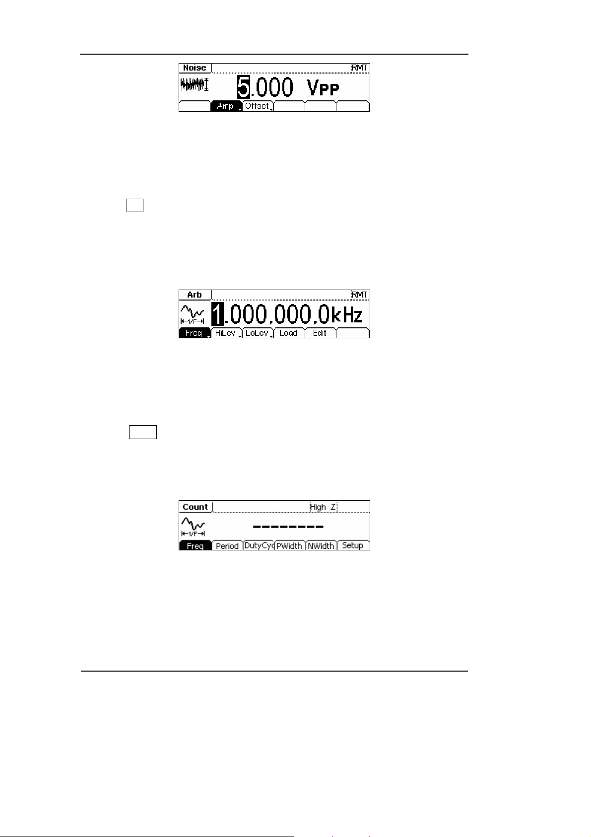
5. Press Noise button, and the waveform icon turns into Noise with a “Noise”
typeface in the state area. DG1000 Series Generator can generate Noise signal
with Band Width up to 5MHz. By setting Amplitude/ High Level, Offset/ Low level,
Noise signal with different parameters can be generated.
© Copyright RIGOL Technologies, Inc. 2007
User’s Guide for DG1000 Series
1-9
Page 20
RIGOL
Figure 1-14
Noise Signal in the Menu Display Mode
As shown in Figure 1-14, the default signal parameters are: 5.0 V
V
DC Offset.
PP Amplitude and 0
6. Press Arb button, and the waveform icon turns into Arb with an “Arb” typeface in
the state area. DG1000 Series Generator can generate repeatable arbitrary
waveform signals with at most 4K points and 3MHz frequency. By setting
Frequency/Period, Amplitude/ High Level, Offset/ Low level, arbitrary waveform
signals with different parameters can be generated.
Figure 1-15
Arbitrary waveform Signal in the Menu Display Mode
As shown in Figure 1-15, the default Exponential Rise Signal parameters are: 1kHz
Frequency, 5.0 V
PP Amplitude and 0 VDC Offset.
7. Press Count button, and the waveform icon turns into Arb with an “Count”
typeface in the state area. Select “Freq”, “Period”, “PWidth”, “NWidth”, the screen
will display corresponding measure result. Select “Setup” to set the parameters
of input coupling method, sensitivity, trigger level and high frequency on/off.
Figure 1-16
General interface of the counter
1-10
© Copyright RIGOL Technologies, Inc. 2007
User’s Guide for DG1000 Series
Page 21

RIGOL
To Set Modulate/ Sweep/Burst
As shown in Figure 1-17, there are three buttons on the front panel, which are used
for Modulating, sweeping and bursting settings. The instructions below will help you
familiarize with the setting of these functions.
Figure 1-17
Modulate/ Sweep/ Burst button
1. Press Mod button, and a Modulated waveforms will be generated.
Parameters are set by using the menu buttons. The modulated waveform can be
changed by changing the parameters such as Type, Internal/external Modulation,
Depth, Frequency, Waveform, etc.
DG1000 Series can modulate waveform using AM, FM, PM and FSK. Sine, Square,
Ramp or Arbitrary waveforms can be modulated (Pulse, Noise and DC cannot be
modulated).
Figure 1-18
Modulated Waveform Signal in the Menu Display Mode
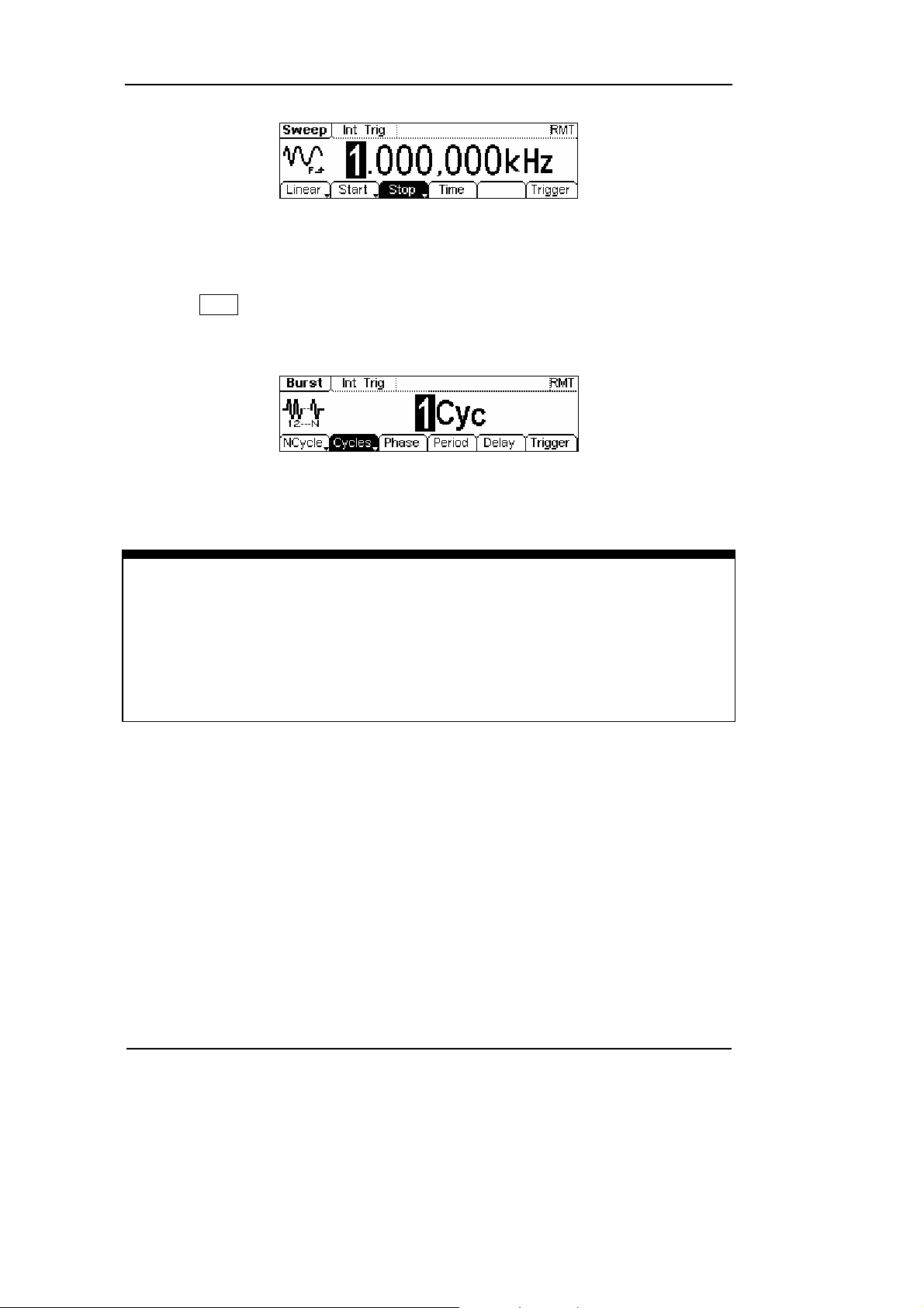
2. Press Sweep button, Sine, Square, Ramp or Arbitrary waveform can be swept
(Pulse, Noise and DC can not be swept).
In the Sweep Mode, DG1000 Series generate signal with variable frequencies.
© Copyright RIGOL Technologies, Inc. 2007
User’s Guide for DG1000 Series
1-11
Page 22
RIGOL
Figure 1-19
Sweep Waveform Signal in the Menu Display Mode
3. Press Burst button, Burst for Sine, Square, Ramp, Pulse or Arbitrary waveform
can be generated (Noise can only be used in the gated Burst).
Figure 1-20
Burst Waveform Signal in the Menu Display Mode
Term Explanation
Burst:Output Waveforms with set cycle times
Burst can last for certain times of waveform cycle (N-Cycle Burst) or be controlled by
external gated signals (Gated Burst). Burst applies to all kinds of waveforms, but
noise can only be used in gated burst.
1-12
© Copyright RIGOL Technologies, Inc. 2007
User’s Guide for DG1000 Series
Page 23
RIGOL
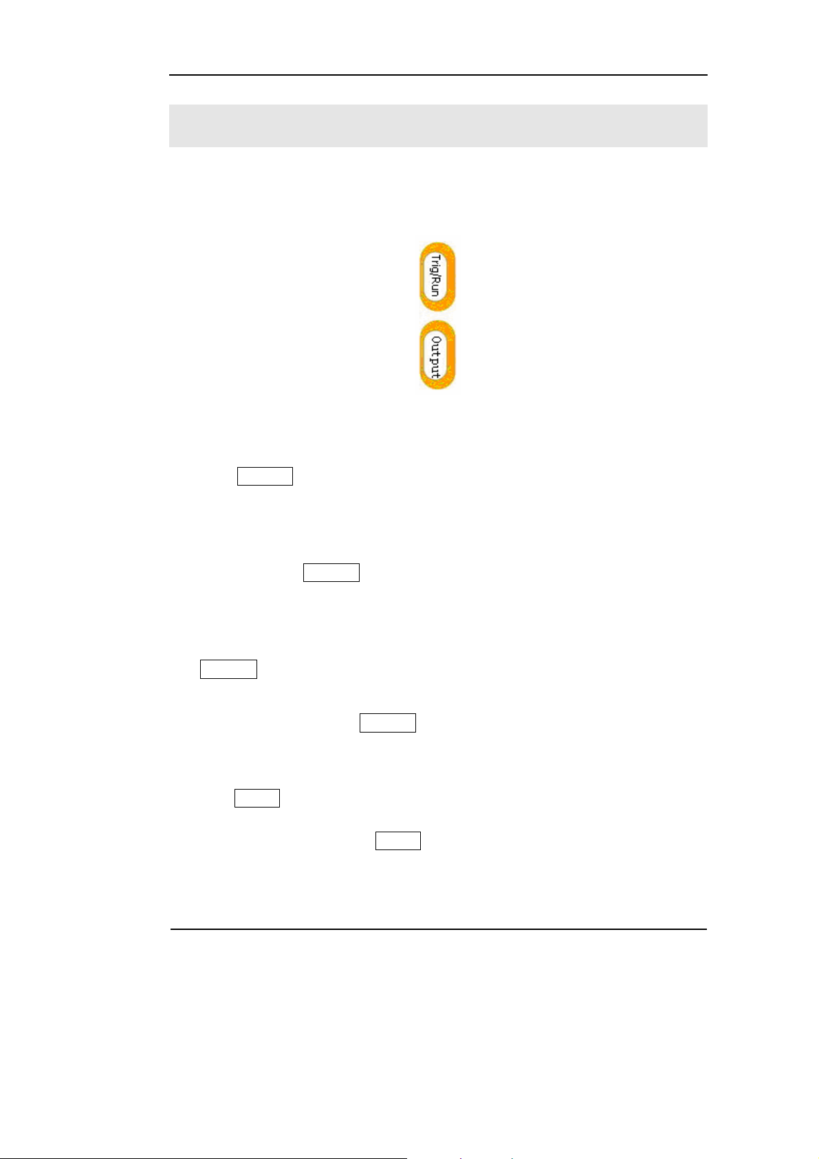
To Set Trigger/Output
As shown in Figure 1-21, there are two buttons on the right side of the operation
panel, which are used to set Trigger and Output Control. The instruction below will
help you to be familiar with these functions.
Figure 1-21
Trigger/ Output Button
1. Press Trig/Run Button, choose internal/ external or manual Trigger (Manual
Trigger can only be used in Sweep and N-Cycle Burst)
The default setting for Trigger is “Internal”. In this mode, when the Sweep or
Burst Mode is also selected, the Generator will continuously generate burst. At
this time, press Trig/Run button, the instrument will shift from the “Automatic”
Trigger mode into “Manual” Trigger mode.
When the generator uses the” External” Trigger Mode, if the Sweep or the Burst
Mode is selected, signal will be continuously generated. At this time, press
Trig/Run button, the instrument state will not change, and it will show “The
instrument has already been triggered”.
Every time you press the Trig/Run button, “Manual” Trigger will start a sweep or
generate a burst. Press the button again, and the generator will be triggered
again.
2. Press Output Button, activate or deactivate the output signal.
If an overload message is shown, disconnect the external equipment from the
output terminals and press Output button, reactivate the output terminal.
© Copyright RIGOL Technologies, Inc. 2007
User’s Guide for DG1000 Series
1-13
Page 24
RIGOL
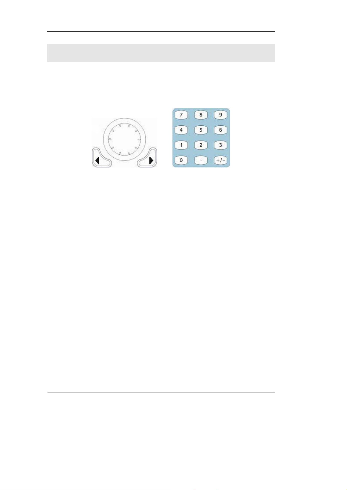
To Use Digital Input
As shown in Figure 1-22, there are two groups of buttons on the operation panel,
which are direction button, the knob and the keypad. The instruction below will help
you to be familiar with the Digital Input Function.
(1) Direction Key and the Knob (2) Keyboard
Figure 1-22
Front Panel Digital Input
1. Use the Direction keys to move the cursor left or right. Rotate the knob to
change a digit (clockwise to increase).
2. Use the Keypad to set the parameters values of the waveforms, which can
change its value directly.
1-14
© Copyright RIGOL Technologies, Inc. 2007
User’s Guide for DG1000 Series
Page 25
RIGOL
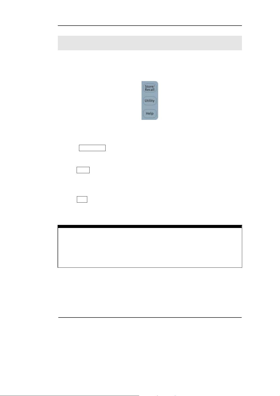
To Use Store/Utility/Help Function
As shown in Figure 1-23, there are three buttons on the operation panel, which are
used to call the store/recall, utility and help function. The instruction below will help
you to be familiar with these Functions.
Figure 1-23
Store/Recall, Utility and Help Button
1. The Store/Recall Button is used to store waveform data and configure
information.
2. The Utility Button is used to set the auxiliary system function, change the output
configure parameters, interface setting, system setting information or perform
the instrument self-test and read the calibration information, etc.
3. The Help Button is used to read the help information.
Operation Instruction
To get help:
To get help on any key of the front panel, press the key and last for 1 second, then
the help message will appear.
© Copyright RIGOL Technologies, Inc. 2007
User’s Guide for DG1000 Series
1-15
Page 26

Page 27

RIGOL
Chapter 2 Operating Your Generator
By now you have got a brief understanding of DG1000 series with the front/rear panel,
every function control area and keys. You should also know how to set your function/
arbitrary waveform generator. If you are not familiar with these operations, please
read Chapter 1 “Getting Started” again.
This chapter covers the following topics:
Menu/Graph Mode ( /A )
Setting Sine Signal ( Sine )
Setting Square Signal ( Square )
Setting Ramp Signal ( Ramp )
Setting Pulse Signal ( Pulse )
Setting Noise Signal ( Noise )
Setting Arb Signal ( Arb )
Setting counter ( Count )
Output Modulated Signal ( Mod )
Output Sweep Signal ( Sweep )
Output Burst Signal ( Burst )
Trigger Sweep or Burst ( Trig/Run )
Store/Recall ( Store/Recall )
Utility Setting ( Utility )
Help System ( Help )
You are suggested to read this chapter carefully so as to understand
DG1000 Series Generator’s versatile waveform setting Functions and the
other operation methods.
© Copyright RIGOL Technologies, Inc. 2007
User’s Guide for DG1000 Series
2-1
Page 28
RIGOL
The Menu/Graph Mode
To activate the Graph Mode
Press /A, enter the Graph Mode. The name of the current selection parameter is
shown on the top left corner of the screen, and its value is shown in inverse color. See
Figure 2-1.
Display Menu
Button
Figure 2-1
Graph Mode Interface
To Select the Desired Parameter
To select the specific parameters, please press any menu button and the operation
menu will pop out. Press the corresponding button to set the parameter. For example,
if you want to change the frequency, press any menu button and select Freq menu.
The direction button will help you find your desired parameter digit and change its
value with the knob or the keypad, see Figure 2-2. In the Graph Mode, the
parameters will still switch at a second press on the button, such as Amp/HiLev.
Current
Parameter
Output waveform
Frequency
Amp
Offset
Operation
Menu
Figure 2-2
Setting the parameters in the Graph Mode
To Quit the Graph Mode
To quit the Graph Mode, press the / A and return the Menu Mode.
2-2
© Copyright RIGOL Technologies, Inc. 2007
User’s Guide for DG1000 Series
Page 29
RIGOL
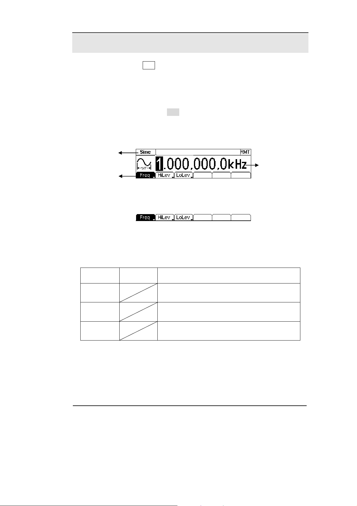
To Set Sine Signals
In the Menu Mode, press Sine Key to call the Sine operation. The top left corner of the
screen will show the name of the current waveform, see Figure 2-3. The output Sine
waveform parameters are set using the Sine operation menu.
The parameters for Sine waveforms are: Frequency/ Period, Amplitude/ High Level,
Offset/ Low Level. Different Sine Signals are generated by using these parameters. As
is shown in Figure 2-4, select Freq in the operation menu and the frequency
parameter will show in the parameter area. Users then can change the frequency by
using the direction button and the knob or the keypad.
Output
Waveform
Current
Operation Menu:
Controlled and
Operated by menu
button
Parameter
Figure 2-3 Sine Signal Parameter Setting Interface
Figure 2-4 Operation Menu
Table 2-1 Operation Menu for Sine Signal
Function
Menu
Frequency/
Period
Amplitude/
High Level
Offset/Low
Level
Settings Explanation
Setting the signal’s frequency or period; the
current parameter will switch at a second press.
Setting the signal’s Amplitude or High Level; the
current parameter will switch at a second press.
Setting the signal’s Offset or Low Level; the
current parameter will switch at a second press
© Copyright RIGOL Technologies, Inc. 2007
User’s Guide for DG1000 Series
2-3
Page 30
RIGOL
To Set the Output Frequency/Period
(1) Press Sine Æ Freq/Period Æ Freq, to set the frequency parameter.
The frequency shown on the screen is the default value when the instrument is
powered or the set value beforehand. When setting the function, if the current value
is valid for the new waveform, it will be used sequentially. If you want to set the
period for the waveform, press Freq/Period button again, switch to the Period
parameter (The current operation is displayed in inverse color).
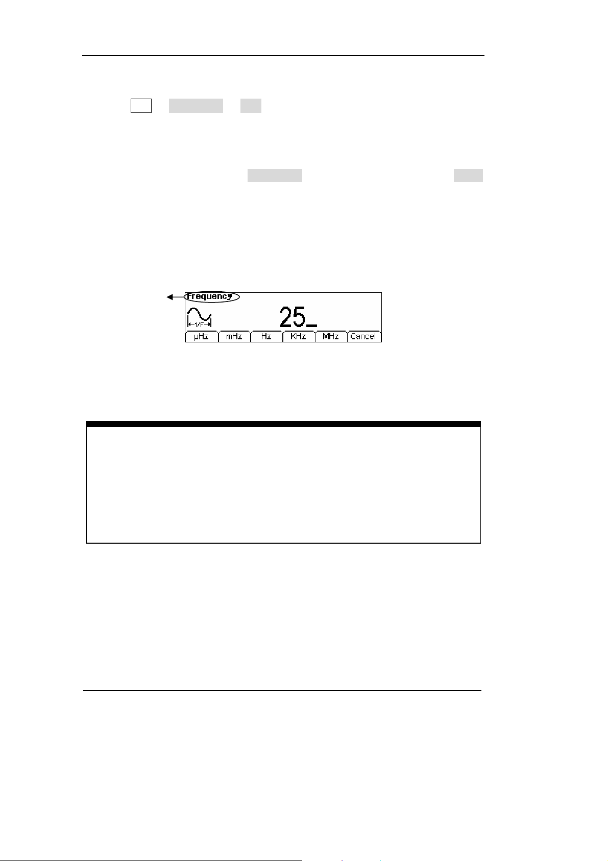
(2) Input the desired frequency.
Use the keypad to input the parameter value directly, and press the corresponding
button to select the parameter unit. Or you can use the direction button to select the
digit you want to edit, and then use the knob to change its value.
Current Parameter:
Frequency
Figure 2-5 Setting the Frequency
Instruction:
When using the keypad to enter the digit, you can use the Left direction button to
move the cursor backward and delete or change the value of the previous digit.
When using the knob to input, use the direction buttons to select the digit you
want to edit and rotate the knob to change its value.
2-4
© Copyright RIGOL Technologies, Inc. 2007
User’s Guide for DG1000 Series
Page 31

RIGOL
To Set the Output Amplitude
(1) Press Sine Æ Ampl/HiLev Æ Ampl, to set the amplitude.
The amplitude shown on the screen is the default value when the instrument is
powered or the set value beforehand. When changing the function, if the current
value is valid for the new waveform, it will be used sequentially. If you want to set the
waveform by high Level or Low Level, press Ampl/HiLev or Offset/Lolev again, switch
to HiLev or LoLev parameter (The current operation is displayed in inverse color).
(2) Input the desired Amplitude
Use the keypad or the knob to input the desired value, choose the unit, and press the
corresponding button.
Current Parameter:
Amplitude
Figure 2-6 Setting the Amplitude
© Copyright RIGOL Technologies, Inc. 2007
User’s Guide for DG1000 Series
2-5
Page 32

RIGOL
To Set the DC Offset
(1) Press Sine Æ Offset/LoLev Æ Offset, to set the offset.
The offset shown on the screen is the default value when the instrument is powered
or the set value beforehand. When changing the function, if the current value is valid
for the new waveform, it will be used sequentially.
(2) Input the desired Offset
Use the keypad or the knob to input the desired value, choose the unit, and press the
corresponding button.
Current Parameter:
Offset
Figure 2-7 Setting the Offset
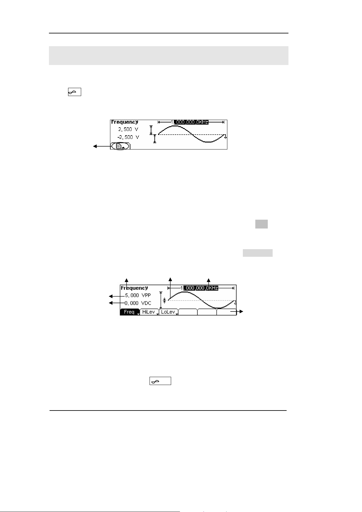
In the Graph Mode, the waveform is shown in Figure 2-8.
Figure 2-8 Waveform Parameter in the Graph Mode
Notes: the Setting of any waveform for DC Offset is the same as sine wave,
so we will not cover this topic hereon.
2-6
© Copyright RIGOL Technologies, Inc. 2007
User’s Guide for DG1000 Series
Page 33

RIGOL
To Set Square Signals
Press Square button, in the Normal Mode, the operation menu will appear at the
bottom of the screen, see Figure 2-9. Set the Square parameters by using the
operation menu.
The parameters for Square waveforms are: Frequency/ Period, Amplitude/ High Level,
Offset/ Low Level and Duty Cycle. See Figure 2-10. In the operation menu, select
DtyCyc, and the corresponding parameter will be displayed in inverse color for which
users can make a change.
Figure 2-9 Square Signal Parameter Setting Interface
Figure 2-10 Operation Menu
Table 2-2 Square Signal Operation Menu
Function
Menu
Frequency/
Period
Amplitude/
High Level
Offset/Low
Level
Duty Cycle Setting the Duty Cycle for Square Waveform
Settings Explanation
Setting the signal’s frequency or period; the
current parameter will switch at a second press.
Setting the signal’s Amplitude or High Level; the
current parameter will switch at a second press.
Setting the signal’s Offset or Low Level; the
current parameter will switch at a second press
© Copyright RIGOL Technologies, Inc. 2007
User’s Guide for DG1000 Series
2-7
Page 34

RIGOL
Term Explanation:
Duty Cycle: The percentage that the High Level takes up in the whole Period.
Please Note : for the Frequency Duty Cycle Value
Below 3MHz(included): 20% to 80%
From 3MHz to 4MHz (included): 40% to 60%
From 4MHz to 5MHz (included): 50%
2-8
© Copyright RIGOL Technologies, Inc. 2007
User’s Guide for DG1000 Series
Page 35

RIGOL
To Set the Duty Cycle
(1) Press Square Æ DtyCyc, to set the Duty Cycle.
The Duty Cycle shown on the screen is the default value when the instrument is
powered or the set value beforehand. When changing the function, if the current
value is valid for the new waveform, it will be used sequentially.
(2) Input the desired Duty Cycle
Use the keypad or the knob to input the desired value, choose the unit, and press the
corresponding button. The Generator will change the waveform immediately.
Current Parameter:
Duty Cycle
Figure 2-11 Setting the Duty Cycle
In the Graph Mode, the waveform is shown in Figure 2-12.
Figure 2-12 Waveform Parameters in the Graph Mode
© Copyright RIGOL Technologies, Inc. 2007
User’s Guide for DG1000 Series
2-9
Page 36

RIGOL
To Set Ramp Signals
Press Ramp button, in the Normal Mode, the operation menu will appear at the
bottom of the screen, see Figure 2-13. Set the Ramp parameters by using the
operation menu.
The parameters for Ramp waveforms are: Frequency/ Period, Amplitude/ High Level,
Offset/ Low Level and Symmetry. See Figure 2-14. In the operation menu, select
Symm, and the corresponding parameter will be displayed in inverse color for which
users can make a change.
Figure 2-13 Ramp Signal Parameter Setting Interface
Figure 2-14 Operation Menu
Table 2-3 Ramp Signal Operation Menu
Function
Menu
Frequency/
Period
Amplitude/
High Level
Offset/Low
Level
Symmetry Setting the Symmetry for Ramp Waveform
Term Explanation:
Symmetry: The percentage that the Rising Period takes up in the whole Period.
Input Range: 0~100%
Settings Explanation
Setting the signal’s frequency or period; the
current parameter will switch at a second press.
Setting the signal’s Amplitude or High Level; the
current parameter will switch at a second press.
Setting the signal’s Offset or Low Level; the
current parameter will switch at a second press
2-10
© Copyright RIGOL Technologies, Inc. 2007
User’s Guide for DG1000 Series
Page 37

RIGOL
To Set the Symmetry
(1) Press Ramp Æ Symm, to set the Symmetry.
The Symmetry shown on the screen is the default value when the instrument is
powered or the set value beforehand. When changing the function, if the current
value is valid for the new waveform, it will be used sequentially.
(2) Input the desired Symmetry.
Use the keypad or the knob to input the desired value, choose the unit, and press the
corresponding button. The Generator will change the waveform immediately.
Current Parameter:
Symmetry
Figure 2-15 Setting the Symmetry
In the Graph Mode, the waveform is shown in Figure 2-16.
Figure 2-16 Waveform Parameter in the Graph Mode
© Copyright RIGOL Technologies, Inc. 2007
User’s Guide for DG1000 Series
2-11
Page 38

RIGOL
To Set Pulse Signals
Press Pulse button, in the Normal Mode, the operation menu will appear at the
bottom of the screen, see Figure 2-17. Set the Pulse parameters by using the
operation menu.
The parameters for Pulse waveforms are: Frequency/ Period, Amplitude/ High Level,
Offset/ Low Level Pulse Width and Duty Cycle. See Figure 2-18. In the operation
menu, select Width, and the corresponding parameter will be displayed in inverse
color for which users can make a change.
Figure 2-17 Pulse Signal Parameter Setting Interface
Figure 2-18 Operation Menu
Table 2-4 Pulse Signal Operation Menu
Function
Menu
Frequency/
Period
Amplitude/
High Level
Offset/Low
Level
Width/
DtyCyc
Settings Explanation
Setting the signal’s frequency or period; the
current parameter will switch at a second press.
Setting the signal’s Amplitude or High Level; the
current parameter will switch at a second press.
Setting the signal’s Offset or Low Level; the
current parameter will switch at a second press.
Setting the Pulse Width or Duty Cycle for Pulse
Waveform.
Term Explanation:
Pulse Width: The time span between thresholds of 50% of the rising edge
amplitude to the next 50% of the falling edge amplitude.
2-12
© Copyright RIGOL Technologies, Inc. 2007
User’s Guide for DG1000 Series
Page 39

RIGOL
To Set the Pulse Width
(1) Press Pulse Æ Width, to set the Pulse Width.
The Pulse Width shown on the screen is the default value when the instrument is
powered or the set value beforehand. When changing the function, if the current
value is valid for the new waveform, it will be used sequentially.
(2) Input the desired Pulse Width
Use the keypad or the knob to input the desired value, choose the unit, and press the
corresponding button. The Generator will change the waveform immediately.
Current Parameter:
Pulse Width
Figure 2-19 Setting the Pulse Width
In the Graph Mode, the waveform is shown in Figure 2-20.
Figure 2-20 Waveform parameters in the Graph mode
Note: Pulse width and Duty cycle are equivalent, once a parameter is changed, the
other one will change accordingly. For instance, the current period is1ms, the pulse
width is 500µs and the duty cycle is 50%, when setting the pulse width to be 200µs,
the duty cycle will become 20%.
© Copyright RIGOL Technologies, Inc. 2007
User’s Guide for DG1000 Series
2-13
Page 40
RIGOL
To Set Noise Signals
Press Noise button, in the Normal Mode, the operation menu will appear at the
bottom of the screen, see Figure 2-21. Set the Pulse parameters by using the
operation menu.
The parameters for Noise waveforms are: Amplitude/ High Level and Offset/ Low
Level. See Figure 2-22. In the operation menu, select Ampl, and the corresponding
amplitude will be displayed in inverse color for which users can make a change for
the amplitude of Noise, which has no frequency or period.
Figure 2-21 Noise Signal Parameter Setting Interface
Figure 2-22 Operation Menu
Table 2-5 Noise Signal Operation Menu
Function
Menu
Amplitude/
High Level
Offset/Low
Level
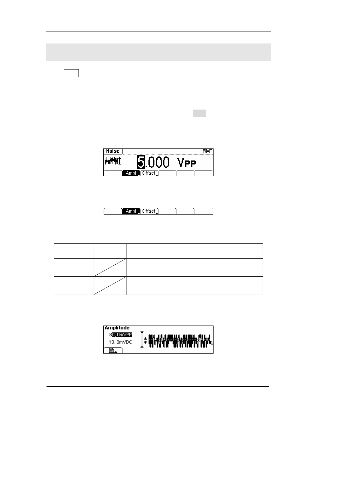
In the Graph Mode, the waveform is shown in Figure 2-23.
Settings Explanation
Setting the signal’s Amplitude or High Level; the
current parameter will switch at a second press.
Figure 2-23 Waveform Parameter in the Graph Mode
Setting the signal’s Offset or Low Level; the
current parameter will switch at a second press
2-14
© Copyright RIGOL Technologies, Inc. 2007
User’s Guide for DG1000 Series
Page 41

RIGOL
To Set Arbitrary Signals
Press Arb button, in the Normal Mode, the operation menu will appear at the bottom
of the screen, see Figure 2-24. Set the Arbitrary Waveform parameters by using the
operation menu.
Arbitrary Signals are divided into two categories: the built-in optional system
waveforms and the user-definable arbitrary waveforms. The parameters for Arbitrary
Waveforms are: Frequency/ Period, Amplitude/ High Level and Offset/ Low Level. See
Figure 2-25. In the operation menu, select Freq, and the corresponding frequency will
be displayed in inverse color for which users can make a change.
Figure 2-24
Arbitrary Signal Parameter Setting Interface
Figure 2-25 Operation Menu
Table 2-6 Arbitrary Signal Operation Menu
Function
Menu
Frequency/
Period
Amplitude/
High Level
Offset/Low
Level
Load Select the built-in Arbitrary Signal as Output.
Edit Create and Edit Arbitrary Waveform.
Settings Explanation
Setting the signal’s frequency or period; the
current parameter will switch at a second press.
Setting the signal’s Amplitude or High Level; the
current parameter will switch at a second press.
Setting the signal’s Offset or Low Level; the
current parameter will switch at a second press.
© Copyright RIGOL Technologies, Inc. 2007
User’s Guide for DG1000 Series
2-15
Page 42

RIGOL
To Select the built-in Arbitrary Waveform
There are five built-in Arbitrary Waveforms and user-definable Arbitrary Waveforms
inside the Generator. To select one of them, following the instructions below:
Press Arb Æ Load, enter the interface shown below.
Figure 2-26 Operation Menu
Table 2-7 Selection Menu for Built-in Arbitrary Waveform
Function
Menu
Built-in
Stored
Volatile
Delete
Settings Explanation
Select one of the five built-in Arbitrary Waveforms
(See Table 2-8)
Select one of Arbitrary Waveforms stored in the
Non-volatile memory.
Select one of Arbitrary Waveforms stored in the
Volatile memory. When a new waveform is
created, the old one will be erased.
Delete one of the Arbitrary Waveforms stored in
the Non-volatile memory. The five Built-in
Waveforms can not be deleted.
Cancel the current operation, and return to the
upper menu. (The rest are the same and will not
be covered)
Instructions:
1. When there is no waveform stored in the Non-Volatile Memory, the
Stored Menu and the Delete Menu will hide.
2. When there is no waveform in the Volatile Memory, the Volatile menu will
hide.
2-16
© Copyright RIGOL Technologies, Inc. 2007
User’s Guide for DG1000 Series
Page 43

1. To Select the Built-in Waveform
Press Arb Æ Load Æ BuiltIn, enter the following interface.
Figure 2-27 Operation Menu
Table 2-8 The Built-in Arbitrary Waveforms Menu
RIGOL
Function
Menu
ExpRise
ExpFall
Settings Explanation
Select the built-in Exponential Rise Waveform
Select the built-in Exponential Fall Waveform
NegRamp
Sinc
Select the built-in Negative Ramp Waveform
Select the built-in Sinc Waveform. Sinc=Sin(x)/x
Cardiac Select the built-in Cardiac Waveform
Cancel
In the Graph Mode, the waveform is shown in Figure 2-28.
Figure 2-28
Waveform Parameter in the Graph Mode (Exponential Rising Waveform)
© Copyright RIGOL Technologies, Inc. 2007
User’s Guide for DG1000 Series
2-17
Page 44

RIGOL
2. To Select the Stored Waveform
Press Arb Æ Load Æ Stored, and enter the following interface. Select the
desired waveform document which will be displayed in inverse color and press Recall
to recall it from the memory.
Figure 2-29 Operation Menu
Table 2-9 The Stored Arbitrary Waveform Menu
Function
Menu
Settings Explanation
Local
Disk
U Disk
Choose display route for the
system information
(When U Disk
is connected )
Setting of the Generator
Arbitrary waveform file
All types of documentation
Type
State
Data
All
Recall the waveform or Setting
Recall
information in the specific
position in the memory.
Store
Remove
Save the waveform to the
appointed place
Remove any waveform that
has been stored in the memory
Instructions:
When there is no waveform stored in the Arb1, Arb2, Arb3 and Arb4, this menu
will hide (The rest is the same and will not explain again)
2-18
© Copyright RIGOL Technologies, Inc. 2007
User’s Guide for DG1000 Series
Page 45

RIGOL
3. To Remove the Waveform
Press Arb Æ Load Æ Stored, and enter the following interface. Select the waveform
documentation to be deleted which will be displayed in inverse color, and then press
Remove to delete it.
Figure 2-30 Operation Menu
Table 2-10 Waveform Removal Menu
Function
Menu
Disk
Type
Recall
Store
Remove
Settings Explanation
Local
Choose display route for the
U Disk
system information
(When U disk
is connected )
State
Data
All
Setting of the Generator
Arbitrary waveform file
All types of documentation
Recall the waveform or Setting
information in the specific
position in the memory.
Save the waveform to the
appointed place
Remove any waveform that
has been stored in the memory
© Copyright RIGOL Technologies, Inc. 2007
User’s Guide for DG1000 Series
2-19
Page 46

RIGOL
To Edit the Arbitrary Waveform
The Generator allows users to edit Arbitrary Waveforms, which can create any new
waveform by initializing points. The operation steps are as follows:
Press Arb Æ Edit, enter the interface shown below.
Figure 2-31 Operation Menu
Table 2-11 Waveform Edition Operation Menu
Function
Menu
Creat
Stored
Volatile
Delete
Settings Explanation
Create a new waveform, and erase the waveform
in the Volatile memory.
Edit the waveform stored in the non-Volatile
memory
Edit the waveform stored in the Volatile memory
Delete one of the Arbitrary Waveforms stored in
the Non-volatile memory. But The five Built-in
Waveforms can not be deleted.
Instructions:
1. When there is no waveform stored in the Non-Volatile Memory, the Stored
Menu and the Delete Menu will hide.
2. When there is no waveform in the Volatile Memory, the Volatile menu will
hide.
2-20
© Copyright RIGOL Technologies, Inc. 2007
User’s Guide for DG1000 Series
Page 47

1. To Create a New Waveform
Press Arb Æ Edit Æ Creat, to set the overall parameters for the waveform.
The setting interface is shown in Figure 2-32 and the menu in Table 2-12.
Figure 2-32
Interface for setting the new waveform parameters
Figure 2-33 Operation Menu
Table 2-12 Setting the parameters for the new waveform
RIGOL
Function
Menu
Settings Explanation
Period Setting the Period for the Waveform
LevelHi Setting the Level High for the Waveform
LevelLo
Setting the Level Low for the Waveform
Activate the linear Interpolation between the
Interp On/
Off
defined points
Deactivate the linear Interpolation between
the defined points
Points
Set the number of points when Initializing
the waveform
EditPt Start the Waveform Editor
© Copyright RIGOL Technologies, Inc. 2007
User’s Guide for DG1000 Series
2-21
Page 48

RIGOL
To Set the Point Number
Press Points, set the number of the initializing points.
When a new waveform is created, the waveform editor will firstly create a waveform
with two points. The Waveform Editor connects the last point to the Voltage Level of
point #1 to create a continuous waveform automatically. A waveform with at most
4K points can be created.
In the default setting, point #1 is Level High, fixed on 0 second, while point #2 is
Level Low and on the half of the set Cycle period.
To Set the Interpolation
Press Interp, if you choose Interpolation On, and the points will be connected with
beelines; otherwise, the voltages between the two consecutive points will not
change, and the waveform looks like a step-up one.
To Edit the Waveform Points
Press Arb Æ Edit Æ Creat Æ EditPt, The waveform can be defined by setting the time
and voltage for each point using this function. The interface is as follows:
Figure 2-34 Operation Menu
2-22
© Copyright RIGOL Technologies, Inc. 2007
User’s Guide for DG1000 Series
Page 49

Table 2-13 Waveform Parameter Edition Menu
RIGOL
Function
Menu
Settings Explanation
Point# Select the point to be edited
Time Set time for the Selected point
Voltage
Set Voltage for the Selected point
Insert a new point between the
Insert
defined points. Use the “Time” and
“Voltage” to define the new point.
Remove
Save
Remove the current point
Save the created waveform to the
non-Volatile Memory.
Instruction:
The time for the last definable point should be less than the cycle period in the
waveform.
© Copyright RIGOL Technologies, Inc. 2007
User’s Guide for DG1000 Series
2-23
Page 50

RIGOL
Save the Waveform to the Non-Volatile Memory
Press Arb Æ Edit Æ Creat Æ EditPt Æ Save, enter the following interface. Select the
desired waveform document to be saved, which will be displayed in inverse color and
press Save to save it to the specific place.
Figure 2-35 Operation Menu
Table 2-14 Save New Waveform Menu
Function
Menu
Settings Explanation
Local
Disk
U Disk
(When a U
Choose display path for the
system information
disk is
connected )
Setting of the Generator
Arbitrary waveform file
All types of documentation
Type
State
Data
All
Recall the waveform or Setting
Recall
information in the specified
position in the memory.
Store
Remove
Save the waveform to the
appointed place
Remove any waveform that
has been stored in the memory
Instruction
To save the Arbitrary Waveform:
In the Non-volatile Memory, each waveform storage place can only save one
waveform. If a new one is stored, the old one will be erased.
2-24
© Copyright RIGOL Technologies, Inc. 2007
User’s Guide for DG1000 Series
Page 51

RIGOL
In the Graph Mode, the waveform is shown in Figure 2-36.
The default Arbitrary
Waveform
Figure 2-36
Waveform Parameter in the Graph Mode
© Copyright RIGOL Technologies, Inc. 2007
User’s Guide for DG1000 Series
2-25
Page 52

RIGOL
2. To Edit the Stored Waveform
Press Arb Æ Edit Æ Stored, enter the following interface. Select the desired
waveform document to be edited, which will be displayed in inverse color and press
Recall to recall and edit it in the Volatile memory.
Figure 2-37 Operation Menu
Table 2-15 Edit Stored Waveform Menu
Function
Menu
Settings Explanation
Local
Disk
U Disk
(When a U
Choose display path for the
system information
disk is
connected )
Setting of the Generator
Arbitrary waveform file
All types of documentation
Type
State
Data
All
Recall the waveform or Setting
Recall
information in the specified
position in the memory.
Store
Remove
Save the waveform to the
appointed place.
Remove any waveform that
has been stored in the memory
3. To Delete a Waveform
Press Arb Æ Edit Æ Delete, to delete a waveform. Select the desired waveform to be
deleted which will be displayed in inverse color and press Remove to delete it.
2-26
© Copyright RIGOL Technologies, Inc. 2007
User’s Guide for DG1000 Series
Page 53

RIGOL
To Set Counter
Press Count , in the normal mode, the screen display the operation menu of the
counter, see figure 2-38. Press “Freq”, “Period”, “DutyCyc”, “PWidth” and “NWidth”,
the instrument will display measurement values of the frequency, period, duty cycle,
positive width and negative width. Press Setup to set the measurement parameters.
To set measurement parameters of the counter containing: AC or DC, sensitivity, Trig
Level, High frequency on or off. Different settings make different measurement
results.
Figure 2-38
Normal display interface of the counter
Figure 2-39 Operation menu
Table 2-16 Operation menu of the counter
Function
menu
Freq
Period
DutyCyc
PWidth
NWidth
Settings Explanation
Display the frequency of the
signal to be measure
Display the period of the signal
to be measure
Display the duty cycle of the
signal to be measure
Display the positive width of
the signal to be measure
Display the negative width of
the signal to be measure
To set the measurement
Setup
parameters of the counter
(Coupling way, sensitivity, trig
level)
© Copyright RIGOL Technologies, Inc. 2007
User’s Guide for DG1000 Series
2-27
Page 54

RIGOL
To set the Auto measure
The counter can automatically detect signal with amplitude from 200mVPP to 5VPP and
frequency form 1Hz to 200MHz. If there is signal that meet the request, press
Trig/Run, it will automatically set the parameters of trig level, the sensitivity and the
high frequency to be on or off.
To set the coupling mode
Press Count Æ Setup Æ DC/AC , to set the coupling mode.
See figure 2-40, the soft key with “DC” or “AC” is the current coupling mode, each
time you press the key, the coupling mode will change. For example, the current
mode is “AC”, press the key, then the mode will be “DC”.
2-28
Figure 2-40
To set the coupling mode
© Copyright RIGOL Technologies, Inc. 2007
User’s Guide for DG1000 Series
Page 55

RIGOL
To set the sensitivity
The Sensitivity has three kinds: High, Medium and Low.
Press Count Æ Setup Æ Sensitivity, to set the sensitivity. Both display on the
left of the screen or in grounding dark color key are the current sensitivity. Press the
corresponding soft key to switch the sensitivity.
For example, the current sensitivity is “Low”, press “High” to switch to be “high”, see
figure 2-41.
Suggest: For low amplitude signal, the “medium” or “high” sensitivity
should be used. and for low frequency signal with high amplitude and
slower rising edge, low sensitivity is a better choice.
Figure 2-41 To set the sensitivity
© Copyright RIGOL Technologies, Inc. 2007
User’s Guide for DG1000 Series
2-29
Page 56

RIGOL
To set the Trig Level
The trig level (-3V~+3V) is divided into share, each “0.1” is 6 mV, it means the
adjustment interval is 6 mV. For example, the input is “62.0”, then the trig level is set
to be : -3V + (62.0 / 0.1) × 6 mV = 0.72V.
(1) Press Count Æ Setup Æ TrigLev , to set the trig level.
The trig level display on the screen is the default value when power on or the value
set at the last time. If the current value is effective, it could be use immediately.
(2) Input the required trig level.
Use the digits keyboard of the knob, input the required parameter, the counter will
immediately adjust the trig level, and trigger according to the specified value.
Figure 2-42 To set the trig level
Note: In the DC coupling mode, users are need to adjust the trig level
manually.
2-30
© Copyright RIGOL Technologies, Inc. 2007
User’s Guide for DG1000 Series
Page 57

RIGOL
To set the High Frequency Restrain On/Off
High frequency restrain is used for filtering the high frequency signal in measuring
the low frequency signal, and improve the measure accuracy.
Press Count Æ Setup Æ HFR On/Off , to set the high frequency restrain to
be on or off.
See figure 2-43, the soft key of “HFR On” or “HFR Off” is the current state, each time
you press the key, the state will change to another one.
Figure 2-43
To set the high frequency on/off
Suggest: To measure low frequency signal lower than 1kHz, you should
put on the high frequency restrain to filter the high frequency noise
disturb. To measure high frequency signal higher than 1kHz, you should
put off the high frequency restrain.
© Copyright RIGOL Technologies, Inc. 2007
User’s Guide for DG1000 Series
2-31
Page 58

RIGOL
To Generate the Modulated Waveform
Use the Mod button to generate modulated waveform. DG1000 Series can generate
AM, FM, FSK, PM modulated waveforms. The modulation parameters should be set in
different types of modulation. For example, In AM, users can set the Source (Internal/
External), depth, Modulating Frequency, Modulating Waveform and Carrier Waveform;
in FM, users can set the Source (Internal/ External), Frequency Deviation, Modulating
Waveform and Carrier Waveform; in FSK, users can set the Source (Internal/
External), Frequency Range, Internal Rate, Modulating Waveform and Carrier
Waveform; while in PM, users can set the Source (Internal/ External), Phase
Deviation, Modulating Frequency, Modulating Waveform and Carrier Waveform, etc.
We will explain how to set these parameters in details according to different types of
modulation.
2-32
Figure 2-44
Modulated Waveform Parameters Interface
© Copyright RIGOL Technologies, Inc. 2007
User’s Guide for DG1000 Series
Page 59

RIGOL
AM
The modulated waveform consists of two parts: the Carrier Waveform and the
Modulating Waveform. In AM, the Amplitude of the Carrier Waveform varies with the
instantaneous voltage of the modulating waveform. The Parameters for the AM are in
Tab l e 2 - 1 7.
Figure 2-45
Modulated Waveform Parameters Interface for AM
Press Mod Æ Type Æ AM, enter the following interface.
Figure 2-46 Operation Menu
Table 2-17 Setting the AM parameters
Function
Menu
Settings Explanation
Type AM Amplitude Modulation
Internal The Source is Internal
SrcInt
SrcExt
External
The Source is External, use the
[Modulation In] connector in the Rear
panel.
Depth Set the amplitude range
Set the modulating waveform
AMFreq
frequency. Frequency Range: 2mHz~
20kHz (Only Internal).
Sine
Square
Choose the modulating Waveform. To
change the Carrier Waveform
parameter, press Sine , Square etc.
Shape
Triangle
UpRamp
DnRamp
Noise
Arb
© Copyright RIGOL Technologies, Inc. 2007
User’s Guide for DG1000 Series
2-33
Page 60

RIGOL
o
In the Graph Mode, the waveform is shown in Figure 2-47.
Depth
Wavef
rm
Source
Type
Frequency
Modulated
Carrier
Figure 2-47 Waveform Parameter in the Graph Mode
Term Explanation
Modulation Depth
The Amplitude Range (also called “percentage Modulation”). Modulation Depth
varies from 0% to 120%.
1. In the 0% Modulation, the output amplitude is the half of the set one.
2. In the 100% Modulation, the output amplitude is the same with the set one.
3. When the modulation is greater than 100%, the instrument output no greater
than 10 V
PP. For an external source, the depth of AM is controlled by the voltage
level of the connector connected to the [Modulation In]. +5V corresponds to the
currently set depth.
2-34
© Copyright RIGOL Technologies, Inc. 2007
User’s Guide for DG1000 Series
Page 61

RIGOL
FM
The modulated waveform consists of two parts: the Carrier Waveform and the
Modulating Waveform. In FM, the Frequency of the Carrier Waveform varies with the
instantaneous voltage of the modulating waveform. The Parameters for the FM are as
shown in Figure 2-49.
Figure 2-48
FM Waveform Parameter Setting Interface
Press Mod Æ Type Æ FM, enter the following interface.
Figure 2-49 Operation Menu
Table 2-18 Setting the FM parameters
Function
Menu
Settings Explanation
Type FM Frequency Modulation
SrcInt
SrcExt
Internal Choose the Internal source.
external
Use the rear [Modulation In] linker to
choose the external source.
Set the Frequency Deviation between
Deviat.
the Modulating Waveform and the
Carrier Waveform.
Set the modulating waveform
FMFreq
frequency. Frequency Range: 2mHz~
20kHz (Internal Source Only).
Sine
Square
Press the function key Sine, Square
etc. to choose different Shape of
waveform.
Shape
Triangle
UpRamp
DnRamp
Noise
Arb
© Copyright RIGOL Technologies, Inc. 2007
User’s Guide for DG1000 Series
2-35
Page 62

RIGOL
In the Graph Mode, the waveform is shown in Figure 2-50.
Modulating
Frequency
Frequency
Deviation
Figure 2-50
Waveform Parameter in the Graph Mode
Term Explanation
Frequency Deviation
1. The Deviation should be equal to or less than the Carrier Waveform Frequency.
2. The Sum of the Deviation and the Carrier Frequency should be equal to or less
than maximum frequency of the selected function plus 100 kHz.
3. For an External Source, the Deviation is controlled by the ±5V voltage Level of
the Connector connected to the [Modulation In]. +5V corresponds to the
selected Deviation. Lower external voltage generates less deviation, while
negative voltage reduces the modulated signal frequency to below the
corresponding carrier’s.
2-36
© Copyright RIGOL Technologies, Inc. 2007
User’s Guide for DG1000 Series
Page 63

RIGOL
FSK
The FSK Modulation is a modulation method, the output frequency of which switches
between the two pre-set frequencies (Carrier Waveform Frequency and the Hop
Frequency). The Frequency for the Output Frequency to switch from the carrier
waveform frequency to and from the Hop frequency is called the FSK rate. The
frequency by which the output frequency switch from each other is determined by the
Internal Frequency generator or the Signal Voltage Level offered by the [Trig In]
connector on the rear panel:
z If you choose the Internal Modulation, the frequency at which the output
frequency shift between the carrier frequency and the Hop frequency is
determined by the set FSK rate.
z If you choose External Modulation and overlook the FSK rate, the output
frequency is determined by the Voltage Level of the [Trig In] connector on the
rear panel. If the Voltage Level is Low, then generate the carrier frequency; when
the voltage level is high, generate the Hop frequency.
Figure 2-51
FSK Waveform Parameter Setting Interface
Press Mod Æ Type Æ FSK, enter the following interface.
Figure 2-52 Operation Menu
© Copyright RIGOL Technologies, Inc. 2007
User’s Guide for DG1000 Series
2-37
Page 64

RIGOL
Table 2-19 Setting the FM parameters
Function
Menu
Settings Explanation
Type FSK Frequency Shift Keying Modulation
SrcInt
SrcExt
HopFreq
Internal Choose the Internal source.
external
Use the rear [Modulation In] linker to
choose the external source.
Set the Hop Frequency Range:
1µHz~8MHz
Set the frequency at which the output
frequency shifts between the carrier
FSK Rate
frequency and the jumping frequency
(Internal Modulation Only): 2mHz~
50kHz.
In the Graph Mode, the waveform is shown in Figure 2-53.
FSK Frequency
2-38
Figure 2-53
Waveform Parameter in the Graph Mode
© Copyright RIGOL Technologies, Inc. 2007
User’s Guide for DG1000 Series
Page 65

RIGOL
PM
The modulated waveform consists of two parts: the Carrier Waveform and the
Modulating Waveform. In PM, the Phase of the Carrier Waveform varies with the
instantaneous voltage Level of the modulating waveform. The Parameters for the PM
are as shown in Figure 2-55.
Figure 2-54
PM Waveform Parameter Setting Interface
Press Mod Æ Type Æ PM, enter the following interface.
Figure 2-55 Operation Menu
Table 2-20 Setting the PM parameters
Function
Menu
Settings Explanation
Type PM Phase Modulation
SrcInt
SrcExt
Internal Choose the Internal source.
external
Use the rear [Modulation In] linker to
choose the external source.
Set the Phase Deviation between the
Deviat.
Modulating Waveform and the Carrier
Waveform, ranging from 0
o
to 360o
Set the modulating waveform
Freq
frequency. Frequency Range: 2mHz~
20kHz (Internal source Only).
Sine
Square
Press the function key Sine、Square
etc. to choose different Shape of
waveform.
Shape
Triangle
UpRamp
DnRamp
Noise
Arb
© Copyright RIGOL Technologies, Inc. 2007
User’s Guide for DG1000 Series
2-39
Page 66

RIGOL
eviatio
In the Graph Mode, the waveform is shown in Figure 2-56.
Modulating
Frequency
Phase
D
n
Figure 2-56
Waveform Parameter in the Graph Mode
2-40
© Copyright RIGOL Technologies, Inc. 2007
User’s Guide for DG1000 Series
Page 67

RIGOL
To Genera t e S w e e p
In the frequency sweep mode, the function generator “sweep” from the start
frequency to the stop frequency at the sweep rate you specify. Sweeping can be
generated by Sine, Square, Ramp or Arbitrary Waveforms (Pulse, Noise and DC are
not allowed).
Figure 2-57
Sweep Waveform Parameter Setting Interface
Press Sweep button, in the Normal Mode, the operation menu will appear on the
bottom of the screen, see Figure 2-58. Set the Waveform parameters by using the
operation menu.
Figure 2-58
Operation Menu
© Copyright RIGOL Technologies, Inc. 2007 2-41
User’s Guide for DG1000 Series
Page 68

RIGOL
Table 2-21 Waveform Sweep Setting Menu
Function
Menu
Linear
log
Start
Center
Stop
Span
Time
Trigger
Settings Explanation
Set the Sweep with linear spacing
Set the Sweep with logarithmic spacing
Set the Start Frequency of the Sweep
Set the Center Frequency of the Sweep
Set the Stop Frequency of the Sweep
Set the Frequency Span of the Sweep
Set the Time Span of the Sweep for which the Frequency
changes from the Start Frequency to Stop Frequency.
Int: Choose Internal Source
Ext: Choose External Source, use the [Modulation In]
Source
connector in the rear panel
Manual: Choose External Source, set the start and stop
time by hand
: Signal Triggered at Rise Edge
TrigOut
: Signal Triggered at Fall Edge
Off: Turn off Trigger Setting
Finish Setting
2-42
© Copyright RIGOL Technologies, Inc. 2007
User’s Guide for DG1000 Series
Page 69

RIGOL
Sweep Frequency Setting
Use Start and Stop or Center and Span to set the range of the frequency. Press the
button again to switch to each other.
z To Sweep upward, set the Start Frequency lower than the Stop Frequency, or set
a positive frequency interval.
z To Sweep downward, set the Start Frequency higher than the Stop Frequency, or
set a negative frequency interval.
© Copyright RIGOL Technologies, Inc. 2007 2-43
User’s Guide for DG1000 Series
Page 70
RIGOL
To Generate Burst
Burst Function can generate versatile waveforms in burst, which can last specific
times of waveform cycle(N-Cycle Burst), or when the external gated signals( Gated
Burst) is applied, any waveform could be used, but noise can only be used in Gated
Burst.
Press Burst button, in the Normal Mode, the operation menu will appear on the
screen, see Figure 2-59. Set the Waveform parameters by using the operation menu.
Figure 2-59
Burst Waveform Parameter Setting Interface
2-44
© Copyright RIGOL Technologies, Inc. 2007
User’s Guide for DG1000 Series
Page 71

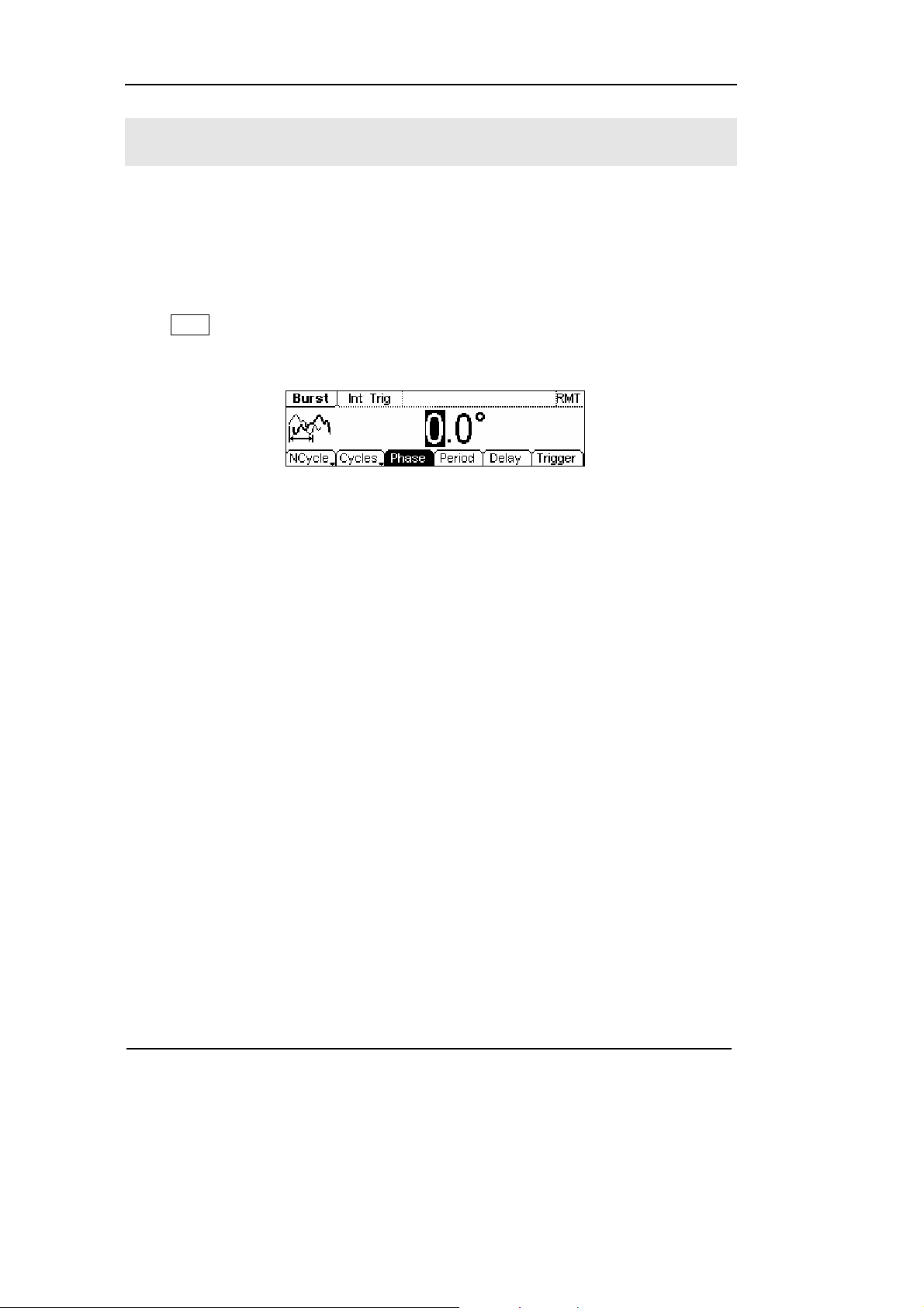
Set the N-Cycle Burst
Press Burst Æ NCycle, enter the following interface.
Figure 2-60 Operation Menu
Table 2-22 Setting the N-Cycle parameters
RIGOL
Function
Menu
N-Cycle
Gated
Cycles
Infinite
Phase Set the Start Phase of the Burst
Period Set the Period of the Burst
Delay Set the Delay for the burst
Trigger
Settings Explanation
Source
TrigOut
Use the N-Cycle Mode
Use the Gated Mode
Set the Number of the bursts in a N-Cycle
Set the Number of the bursts in a N-Cycle
to be infinite
Int: Choose Internal Source
Ext: Choose External Source, use the
[Modulation In] connector in the rear
panel
Manual: Choose External Source, set the
start and stop time by hand
: Signal Triggered at Rise Edge
: Signal Triggered at Fall Edge
Off: Turn off Trigger Setting
Finish Setting
© Copyright RIGOL Technologies, Inc. 2007 2-45
User’s Guide for DG1000 Series
Page 72

RIGOL
N-Cycle/ Gated
N-Cycle has specific number of waveform cycles, and every burst is activated by a
trigger event. Gated burst use external source to control burst when to be activated.
Cycle Number
Set the number of Waveform Cycle in an N-Cycle (1 to 50,000 or Infinite).
If you choose Infinite, then a continuous waveform will be generate which will not
stop until a trigger event happens (Trig/Run button is pressed).
z If needed, Burst Period will increase to cater to the specific number of cycles.
z For an infinite-cycle Burst, External or Manual Trigger is needed to activate burst.
Phase
Define the Start and the Stop Point in a waveform. The phase varies from -360° to
+360°, and the default setting is 0°. For an Arbitrary Waveform, 0° is the phase of the
first waveform point.
Period
Set the time span between an N-Cycle Burst to the next. If necessary the period will
increase to allow the specific number of cycles in a burst.
Burst Period> Period X Burst Number
Delay
Set the Time Delay between the Trigger Input and the Start of the N-Cycle Burst. The
minimum delay is a function of the specific burst period, and should always be
greater than 0.
In the Graph Mode, the waveform is shown in Figure 2-61.
Burst Period
Start Phase
Delay
N-Cycle
Cycle Times
Figure 2-61
Waveform Parameter in the Graph Mode
2-46
© Copyright RIGOL Technologies, Inc. 2007
User’s Guide for DG1000 Series
Page 73

Set the Gated Burst
Press Burst Æ Gated, enter the following interface.
Figure 2-62 Operation Menu
Table 2-23 Setting the Gated parameters
RIGOL
Function
Menu
NCycle
Gated
Polarity
Phase
Settings Explanation
Set the Gated Mode
Pos
Neg
Set the Polarity for the Gated Signal
Set the Start Phase for the Gated
Signal
In the Graph Mode, the waveform is shown in Figure 2-63.
Start Phase
Positive Gated Signal
Gated
Figure 2-63
Waveform Parameter in the Graph Mode
© Copyright RIGOL Technologies, Inc. 2007 2-47
User’s Guide for DG1000 Series
Page 74

Page 75

RIGOL
To Store and Re c a l l
Press Store/Recall Button, and the operation menu will appear at the bottom of the
screen. You can save or read the State or Data Documentation inside the Generator
or build and delete documentation in the U Disk. File names can either be Chinese or
English.
Figure 2-64 Save and Read Interface
Figure 2-65 Operation Menu
Table 2-24 Save and Read Menu
Function
Menu
Disk
Type
Recall
Store
Remove
About the Disk
Settings Explanation
Local
U Disk
(When U Disk is
connected )
State
Data
All
Choose display route for the
system information
Setting of the Generator
Arbitrary waveform file
All types of documentation
Recall the waveform or Setting
information in the specific
position in the memory.
Save the waveform to the
appointed place.
Remove any waveform that
has been stored in the memory
Use the Disk button to choose Local or U Disk (When U Disk is connected).
© Copyright RIGOL Technologies, Inc. 2007 2-49
User’s Guide for DG1000 Series
Page 76

RIGOL
To Save the Instrument State
Users are allowed to store the instrument state on any of the 4 Non-Volatile Memories.
When the power is restored, the instrument will return to the state when it is powered
off automatically. The state storage will “memorize” the selected function (including
the Arbitrary Waveform), Frequency, Amplitude, DC Offset, Duty Cycle, Symmetry,
and other modulation parameter used.
To Save the Instrument State, following the steps:
(1) Choose the file Type to store
Press Store/Recall Æ State, and choose the storage type to be “State”.
(2) Choose the location of the file.
There are four positions in the Local STATE1, STATE2, STATE3 and STATE4,
choose one of them by rotating the knob.
(3) Name the file and Save it
Press Store button, enter the desired name. Press Store to finish.
2-50
© Copyright RIGOL Technologies, Inc. 2007
User’s Guide for DG1000 Series
Page 77

RIGOL
To Save Data
Users are allowed to store data document on any of the 4 Non-Volatile Memories. If
the place is already occupied, the new document will cover the old one. To save the
data, following the steps:
(1) Choose the file Type to store
Press Store/Recall Æ State Æ data, and choose “data” as the storage type.
(2) Choose the location of the file.
There are four positions in the Local ARB1, ARB2, ARB3 and ARB4, choose one of
them by rotating the knob.
(3) Name the file and Save
Press Store button, enter the desired name. Press Store to finish.
© Copyright RIGOL Technologies, Inc. 2007 2-51
User’s Guide for DG1000 Series
Page 78

RIGOL
To Use USB storage
As shown in figure 2-66, the storage location is divided into: the inherent Local
storage and the U Disk storage. At the left side of the front panel, there is a USB
interface. When USB storage is connected, the storage menu will show “U Disk”.
Otherwise, the default location is the internal location Local.
Figure 2-66 To use the USB Storage
(1) Install the mobile Storage
Insert the mobile memory to the USB interface on the front panel, and the
screen will show “
(2) Choose the mobile memory
Press Disk, move the cursor upward or downward to select “U Disk”. Choose
Type to be “data” and press Store , enter the file name and then press Store to
save the file.
”.
(3) Uninstall the mobile Storage
Remove the U Disk from the Interface and the system will inform you that the U
Disk has been removed, and the “
” Sign will disappear.
2-52
© Copyright RIGOL Technologies, Inc. 2007
User’s Guide for DG1000 Series
Page 79

RIGOL
To Save a File
Press Store/Recall Æ Store, enter the following interface. Enter the desired file name
in the “File Name” frame. Under the frame is the input keypad. Use the direction
button to select the desired character. When the character is in inverse color, press
Select to input it.
Figure 2-67 File Storage Interface
Figure 2-68 Operation Menu
Table 2-25 File Storage Menu
Function
Menu
Lang
Select Select the current character
Remove
Store Store the file with the current name
Settings Explanation
EN English Input
CN Chinese Input
Cancel the current operation
Delete the current character
© Copyright RIGOL Technologies, Inc. 2007 2-53
User’s Guide for DG1000 Series
Page 80

RIGOL
1. English Input
The English Input Interface is shown in Figure 2-69, to save a file named as “NewFile”,
following the steps below:
File Name
Input
Keypad
Figure 2-69 English Input Interface
(1) Press Lang Æ EN, enter the English Interface.
(2) Input the file name “NewFile”.
Use the Knob to adjust the cursor to the right character, and press Select. Repeat
this until you have selected all the characters needed. Press +/- to choose the
majuscule or lowercase.
(3) Edit the File Name
When you have entered a wrong character, move the cursor to the wrong
character and press Remove to delete it. And then enter the file name again.
(4) Press Store, to finish and save the file.
2-54
© Copyright RIGOL Technologies, Inc. 2007
User’s Guide for DG1000 Series
Page 81

RIGOL
2. Chinese Input
The Chinese Input Interface is shown in figure 2-70. To save a new file, follow the
instructions below:
File Name Input
Input menu
Page Controller
Key Pad
Figure 2-70 Chinese Input Interface
(1) Press Lang Æ CN, enter the Chinese Input Interface.
(2) Press “+/-”to choose the lowercase, and input the spell of the Chinese.
(3) Input the file name: “新文件”
Use the Knob to adjust the cursor to the right character, and press Select. Input
“Xin”. In the Input Menu, choose the Chinese character you need with the help
of the page controller and the 1~9 button on the keypad.
(4) Edit the wrong input
When a file name is wrong, move the cursor to the character and press Remove
to delete it and enter the file name again.
(5) Press Store to finish and save the file.
© Copyright RIGOL Technologies, Inc. 2007 2-55
User’s Guide for DG1000 Series
Page 82

RIGOL
To Set the Utility Function
With the Utility Function, you can set the parameters of the Generator such as: DC
On/Off, Sync On/Off, Output Parameter, Interface Parameter, System Setting and
Testing Parameter. The DC switch offers the options of DC output or Arbitrary
Waveform Output. Sync Switch offers the option to choose the Sync Signal or not.
The output Setting provides the parameter setting for Load/Impedance, Range,
Normal/ Inverse and Phase. The interface Setting offers the storage and load of the
configure parameter setting for USB remote Control. The System Setting provides the
setting for Language, Display, Beep, Screen Guard, Format, Power System Configure
and default setting; the test provides the self-testing and calibration storage as well
as the password and safety switch.
Press Utility to enter the Utility Menu. Its functions are listed below in table 2-26.
Figure 2-71 Operation Menu
2-56
© Copyright RIGOL Technologies, Inc. 2007
User’s Guide for DG1000 Series
Page 83

Table 2-26 Utility System Setting
RIGOL
Function
Menu
DC On
Off
Sync On
Sync Off
Settings Explanation
On Set the output waveform to be DC
Off Set the output waveform to be Arbitrary.
On
Off
Activate the Sync Signal on the [Sync]
Connector on the front panel.
Deactivate the Sync Signal on the [Sync]
Connector on the front panel.
Output Set the Output parameter
I/O Set the I/O
System Set the System Configuration
Test/Cal Test and Calibrate the instrument
Instruction
Sync Switch Setting:
When the amplitude is low relatively, you can reduce the distortion when output
the signal by prohibiting the Sync Signal. And the current storage is in the
Non-Volatile Memory.
© Copyright RIGOL Technologies, Inc. 2007 2-57
User’s Guide for DG1000 Series
Page 84

RIGOL
To Set the DC Output
Press Utility Æ DC On/Off Æ DC On, enter the following interface.
Figure 2-72 The DC Setting Interface
DC Offset
Set the DC Voltage Level.
To Shift into the Arbitrary Waveform Output
(1) Press Utility Æ DC On/Off Æ DC Off, close the DC output and return the output
of the Arbitrary Waveform.
(2) Press any functional button, and the waveform output setting turns to the output
of arbitrary waveform. The DC option is turned off automatically.
In the Graph Mode, the waveform is shown in Figure 2-73.
Offset
Figure 2-73
Waveform Parameter in the Graph Mode
2-58
© Copyright RIGOL Technologies, Inc. 2007
User’s Guide for DG1000 Series
Page 85

RIGOL
To Set the Sync Output
The Generator provides Sync output through the [Sync/Counter] Connector on the
Front Panel. All the standard output functions (except DC and Noise) have a
corresponding Sync Signal. For some Sync applications, they can be prohibited if
users do not want to use them.
• In the default setting, the Sync Signal output is disabled, the output Voltage of
the [Sync/Counter] Connector Level is Low.
• In the Inverse Mode, the Waveform that corresponds to the Sync Signal does not
Inverse.
• If frequency of the standard output function (except DC and Noise) is higher
than 2MHz, the Sync output will automatically put off.
• For Sine, Square and Pulse Signal, the Sync Signal is a Square Signal with 50%
Duty Cycle. When the output is positive, The Sync Signal is TTL Level High
compared to 0 V Voltage or DC Offset; when the output is negative, The Sync
Signal is TTL Level Low compared to 0 V Voltage or DC Offset.
• For Square Waves, the Sync Signal is a Square Wave with the same Duty Cycle
with the main output Square Wave. When the Output is positive, The Sync Signal
is TTL Level High compared to 0 V Voltage or DC Offset; when the output is
negative, The Sync Signal is TTL Level Low compared to 0 V Voltage or DC
Offset.
• For Arbitrary Waveform, the Sync Signal is a Square Waveform with 50% Duty
Cycle. At the time when the first output waveform point is generated, the Sync
Signal Voltage is TTL Level High.
• For the internal Modulating of AM, FM and PM, the Sync Signal reference is the
Modulated Signal (not the Carrier Signal). The Sync Signal is a Square Waveform
with 50% Duty Cycle. In the first half modulation period, the Sync Signal is TTL
Level High. For External Modulation, the Sync Signal reference is the Carrier
Signal (not the Modulated Signal). The Sync Signal is also a Square Waveform
with 50% Duty Cycle.
© Copyright RIGOL Technologies, Inc. 2007 2-59
User’s Guide for DG1000 Series
Page 86

RIGOL
• For FSK, the Sync Signal Reference is the Hop Frequency, and the Sync Signal is
a Square Waveform with 50% Duty Cycle. For the Hop Frequency, at the hopping
point, the Sync Signal is TTL Level High.
• For the Burst, when the burst starts, the Sync Signal is Level High. At the specific
point when the Cycle Number ends, the Sync Signal turns Level Low (If the
Waveform has a relative starting phase, then intersections may occur). For an
infinite burst, the Sync Signal is the same as the Sync Signal of the continuous
Signal.
• For the External Gated Burst, the Sync Signal follows the External Gated Signal.
But, please note that this signal will not turn Level Low until the last period end
(If the Waveform has a relative starting phase, it may be not intersections).
2-60
© Copyright RIGOL Technologies, Inc. 2007
User’s Guide for DG1000 Series
Page 87

To Set Output Parameter
Press Utility Æ Output, enter the following interface.
Figure 2-74 Operation Menu
Table 2-27 Operation Setting Menu
RIGOL
Function
Menu
Load
High Z
Range
Normal
Inverse
Phase
Instruction
Hold Range
Select Hold, prohibit the auto optimizing. This will eliminate the” burr” caused by
the switch of the Attenuator. But, the precision and the resolution (the fidelity of
the original waveform) may be affected.
Settings Explanation
Set the Load connected to the Output
Auto
Hold Disable the Auto Adjusting
Connector.
Set the Load connected to the Output
Connector to be High Z.
Allow the Instrument to choose the
best Amplifier/ Attenuator
Normal Output
Inverse Output
Set the Phase Offset of the Output
Waveform
© Copyright RIGOL Technologies, Inc. 2007 2-61
User’s Guide for DG1000 Series
Page 88

RIGOL
1. To Set the Output Load
For the [Output] Connector on the Front panel, the Generator has a built-in 50Ω
series output impedance. If the actual load does not match the set one, the amplitude
and offset displayed are incorrect. This function is used to match the displayed
voltage with the expected one.
Steps for setting the Load value:
(1) Press Utility Æ Output Æ Load, enter the following interface.
Please note that the Load Parameter shown on the right bottom is the default
setting when the power is on or the pre-set load value. If the current value is
valid for the output, then the current value can be used.
(2) Input the desired Load Value.
Use the Keypad or the Knob to enter the desired value and choose the unit, Ω or
KΩ, press the corresponding button.
Figure 2-75 Set the Output Load
Instruction
DG1000 Series have a fixed 50Ω Series impedance no matter what value has been
set for this parameter.
If the real load is different from the set one, the displayed voltage will not equal to
the real voltage.
2-62
© Copyright RIGOL Technologies, Inc. 2007
User’s Guide for DG1000 Series
Page 89

RIGOL
2. To Set the Inverse Waveform
Press Utility Æ Output Æ Inverse, to set the inverse Waveform output.
No offset voltage will change while the waveform is inversed. An inverse waveform
will be displayed in the Graph Mode.
Normal
Figure 2-76 Normal Waveform
Inverse
Figure 2-77 Inverse Waveform
3. To Adjust the Phase
Press Utility Æ Output Æ Phase, enter the following interface.
Set the Phase use the unit of degree.
Figure 2-78 Setting the Phase
© Copyright RIGOL Technologies, Inc. 2007 2-63
User’s Guide for DG1000 Series
Page 90

RIGOL
To Set the I/O
Press Utility Æ I/O, to set the I/O. See Figure 2-79.
Figure 2-79 Operation Menu
Table 2-28 I/O Setting Menu
Function
Menu
USB
Settings Explanation
USB ID=usb0::2391::1031::MY44005
582::INSTK
2-64
© Copyright RIGOL Technologies, Inc. 2007
User’s Guide for DG1000 Series
Page 91

To Set the System
Press Utility Æ System, enter the following interface.
Figure 2-80
Operation Menu
Table 2-29 System Setting Menu
RIGOL
Function
Menu
Lang Set the Display Language
Display Set the parameter for the Screen Display
Beep
On/Off
Svr on/off
Format Set the data format
Setting
Settings Explanation
On Open Beep
Off Close Beep
Activate the Screen Guard Program. Screen
On
Off deactivate the Screen Guard Program
PowOn
Default Return all the setting into the default one
Timer Choose the clock source as: internal/external
Guard will be on if no action is taken within 3
minutes. Press any button the resume.
Default: When the power is on, all the setting
will return to the default value.
Latest: When the power is on, all the setting
will return to the latest setting.
© Copyright RIGOL Technologies, Inc. 2007 2-65
User’s Guide for DG1000 Series
Page 92

RIGOL
Key points:
Power On
The Setting is used when the machine is power on.
Two choices are available: the default setting and the latest. Once selected, the
setting will be used when the instrument is restarted.
Beep
Activate or deactivate the sound when an error occurs from the front panel or the
remote interface. Activate or deactivate any sound made by the button or knob on the
front panel.
2-66
© Copyright RIGOL Technologies, Inc. 2007
User’s Guide for DG1000 Series
Page 93

1. Language Setting
The DG1000 Series Generator offers two languages: Chinese and English.
To Select Language, press Utility and then Lang to select the language.
Press Utility Æ System Æ Lang, change the language.
Figure 2-81 Language Setting Menu
2. Display Control
Press Utility Æ System Æ Display, enter the following menu.
RIGOL
Figure 2-82 Operation Menu
Table 2-30 Display Parameter Setting
Function
Menu
Settings Explanation
Contra Set the Display Contrast Parameter
Light Set the Display Light Parameter
Invert Set the Invert Display
© Copyright RIGOL Technologies, Inc. 2007 2-67
User’s Guide for DG1000 Series
Page 94

RIGOL
3. Set the Format
Press Utility Æ System Æ Format, enter the following interface.
Figure 2-83 Setting the data Format
Table 2-31 Setting the Data Format
Function
Menu
Settings Explanation
Using dot
Decimal
Using comma
Close the Separate.
Enable the Separate
Separat.
No
Space Use Space to separate
On
According to the different choice of the decimal and the separate, the format can
have various forms:
(1) “ ” as decimal, press Separat. Æ On, the example is as follows:
Figure 2-84 Setting the data format
(2) “ ” as decimal, press Separat. Æ On, the example is as follows:
2-68
Figure 2-85 Setting the data format
© Copyright RIGOL Technologies, Inc. 2007
User’s Guide for DG1000 Series
Page 95

(3) “ ” as decimal, press Separat. Æ No, the example is as follows:
Figure 2-86 Setting the data format
(4) “ ” as decimal, press Separat. Æ No, the example is as follows:
Figure 2-87 Setting the data foramt
(5) “ ” as decimal, press Separat. Æ Space, the example is as follows:
RIGOL
Figure 2-88 Setting the data format
(6) “ ” as decimal, press Separat. Æ Space, the example is as follows:
Figure 2-89 Setting the data format
© Copyright RIGOL Technologies, Inc. 2007 2-69
User’s Guide for DG1000 Series
Page 96

RIGOL
4. To Return to Default Setting
Press Utility Æ System Æ Setting Æ Default, return the default setting of the system:
Table 2-32 Default Parameter Setting
Output Default
Function Sine Wave
Frequency 1kHz
Amplitude/Offset 5 VPP /0.000 VDC
Unit VPP
Term i na l s Hi g h Z
Auto Adjustment On
Modulation Default
Carrier 1kHz Sine Wave
Modulating 100Hz Sine Wave
AM Depth
100%
FM Deviation 100Hz
FSK Hop Frequency 10Hz
FSK Frequency 100Hz
2-70
Modulation State Off
Sweep Default
Start/Stop Frequency 100Hz/1kHz
Time 1s
Mode Linear
State Off
Burst Default
Frequency 1kHz
Count 1Cycle
© Copyright RIGOL Technologies, Inc. 2007
User’s Guide for DG1000 Series
Page 97

RIGOL
Period 10ms
Phase 0
°
State Off
Count Default
Coupling AC
Sensitivity High
Trig Lev
71.0 (1.26V)
HFR Off Off
System Default
*Power-down Recall *Disabled
Display On
Error Array Clear Error
Storage State and any
No change
Waveform
Output State Off
Trigger Default
Source Internal
Calibration Default
State Coded
The parameter with an asterisk (*) is stored in the Non-Volatile Memory.
© Copyright RIGOL Technologies, Inc. 2007 2-71
User’s Guide for DG1000 Series
Page 98

RIGOL
Test
Press Utility Æ Test/Cal, enter the following menu.
Figure 2-90 Test Menu
Figure 2-91 Operation Menu
Table 2-33 Test Setting Menu
Function
Menu
Settings Explanation
Test Perform System Self-Test
Info
Show the information for Calibration times and other related
ones
PassWd Input the password for Secure calibration
Cal Perform the Calibration
SecOn
SecOff
On Turn On Secure Setting, disables the calibration by anyone
Off Turn Off Secure Setting, enables the calibration by anyone
2-72
© Copyright RIGOL Technologies, Inc. 2007
User’s Guide for DG1000 Series
Page 99

RIGOL
1. Test
Press Utility Æ Test / C al Æ Test, to perform self-testing. When the instrument is
powered, the system will perform the self-testing automatically. This limited test can
test if the instrument could work ordinarily. To perform a general test needs 15
seconds. If all the tests have been passed, you can use the generator freely. If the
general test has been passed, the screen will show “Self-Test Passed”; if not, it will
also tell you self-test failed and display the error message.
2. Calibration
The information consist the calibration counting and the edition.
Please note that the generator has been calibrated before it leaved the factory,
When you turn on a new instrument, the default number of the calibration is 0.
You can get the information of the latest version on the company’s website:
http://www.rigol.com.
3. Password
This function is used to prevent unauthorized or accidental calibration to the
generator. When the generator is firstly shipped to the user, it is secured. You have to
unlock it before calibrating the instrument.
Press Utility Æ Test / C al Æ PassWd, and enter the right password. The system will
display “The System is now unsecured”. SecOff will appear, see Figure 2-92, The
default password is “12345”. It is stored in the Non-Volatile Memory, and will not
change when the instrument is powered off or the Remote I/O is reset.
Figure 2-92 Operation Menu
© Copyright RIGOL Technologies, Inc. 2007 2-73
User’s Guide for DG1000 Series
Page 100

RIGOL
How to Use the Built-in Help System
You can get a particular help for every button on the front panel by using the built-in
help system. Or you can get help about the operation of the front panel buttons with
the Help List.
Press Help enter the following interface.
Figure 2-93 Help Menu
Figure 2-94 Operation Menu
Table 2-34 Help Menu
Function
Menu
Settings Explanation
Select Select and read the Information
Page Up
Page Down
Cursor Downward to select
Cursor Upward to select
Exit the help menu
2-74
© Copyright RIGOL Technologies, Inc. 2007
User’s Guide for DG1000 Series
 Loading...