

Page 1

RIGOL
User’s Guide
DP700 Series Programmable
Linear DC Power Sup ply
Apr. 2016
RIGOL TECHNOLOGIES, INC.
Page 2

Page 3

RIGOL
Guaranty and Declaration
Copyright
© 2016 RIGOL TECHNOLOGIES, INC. All Rights Reserved.
Trademark Information
RIGOL is a registered trademark of RIGOL TECHNOLOGIES, INC.
Publication Number
UGH05101-1110
Software Version
00.01.02
Software upgrade might change or add product features. Please acquire the latest
version of the manual from RIGOL website or contact RIGOL to upgrade the
software.
Notices
RIGOL produ cts are cove red by P.R.C. and f oreign pa tents, issue d and pendin g.
RIGOL reserves the right to modify or change parts of or all the specifications
and pricing policies at the company’s sole decision.
Information in this publication re places all previ ously released materials.
Information in this publication is subject to change without notice.
RIGOL shall not be liable for either incidental or consequential losses in
connection with the furnishing, use, or performance of this manual, as well as
any information contained.
Any part of th is d ocu ment is f orbi dden to be c opie d, ph oto copie d, o r rea r ran ged
without prior written approval of RIGOL.
Product Certification
RIGOL guarantees that this product conforms to the national and industrial
standards in China as well as the ISO9001:2008 standard and the ISO14001:2004
standard. Other international standard conformance certifications are in progress.
Contact Us
If you have any problem or requirement when using our products or this manual,
please contact RIGOL.
E-mail: service@rigol.com
Website: www.rigol.com
DP700 User’s Guide I
Page 4

RIGOL
Safety Requirement
General Safety Summary
Please review the following safety precautions carefully before putting the
instrument into operation so as to avoid any personal injury or damage to the
instrument and any product connected to it. To prevent potential hazards, please
follow the instructions specified in this manual to use the instrument properly.
Use Proper Power Cord.
Only the exclusive power cord designed for the instrument and authorized for use
within the local country could be used.
Ground the Instrument.
The instrument is grounded th rou gh t he Protective Earth lead of the p ower cord. To
avoid electric shock, con nect the earth terminal of the power cord to the Protective
Earth terminal before connecting any input or output terminals.
Connect the Probe Correctly.
If a probe is used, the probe ground lead must be connected to earth ground. Do not
connect the ground lead to high volt age. Impr oper w a y of conne ction c ould result in
dangerous voltages being present on the connectors, controls or other surfaces of
the oscilloscope and probes, which will cause potential hazards for operators.
Observe All Terminal Ratings.
To avoid fire or shock hazard, observ e all rat ings and ma rkers on the instrume nt and
check your manual for more information about ratings before connecting the
instrument.
Use Proper Overvoltage Protection.
Ensure that no over voltage (su ch as that cause d by a bolt of lightning ) can reach the
product. Otherwise, the operator might be exposed to the danger of an electric
shock.
Do Not Operate Without Covers.
Do not operate the instrument with covers or panels removed.
Do Not Insert Objects Into the Air Outlet.
Do not insert objects into the air outlet, as doing so may cause damage to the
instrument.
Use Proper Fuse.
Please use the specified fuses.
II DP700 User’s Guide
Page 5

RIGOL
Avoid Circuit or Wire Exposure.
Do not touch exposed junctions and components when the unit is powered on.
Do Not Operate With Suspected Failures.
If you suspect that any damage may occur to the instrument, have it inspected by
RIGOL authorized personnel before further operations. Any maintenance,
adjustment or replacement especially to circuits or accessories must be perfo r med
by RIGOL authorized personnel.
Provide Adequate Ventilation.
Inadequate ventilation may cause an increase of temperature in the instrument,
which would cause damage to the instrument. So please keep the instrument well
ventilated and inspect the air outlet and the fan regularly.
Do Not Operate in Wet Conditions.
To avoid short circuit inside the instrument or electric shock, never operate the
instrument in a humid environment.
Do Not Operate in an Explosive Atmosphere.
To avoid personal injuries or damage to the instrument, never operate the
instrument in an explosive atmosphere.
Keep Product Surfaces Clean and Dry.
T o a void dust or moisture from af fecting the pe rformance of the inst rument, keep th e
surfaces of the instrument clean and dry.
Prevent Ele c tr o static Imp act.
Operate the instrume nt i n an el ectr ostatic dischar ge protectiv e envi ron ment to a void
damage induced by static discharges. Always ground both the internal and external
conductors of cables to releas e sta t i c be fore making connectio ns.
Use the Battery Properly.
Do not expose the battery (if available) to high temperature or fire. Keep it out of the
reach of children. Improper change of a battery (lithium battery) may cause an
explosion. Use the RIGOL specified battery only.
Handle with Caution.
Please handle with care during transportation to avoid damage to keys, knobs,
interfaces, and other parts on the panels.
Do Not Use this Instr ument to Provide Power for the Active Load.
The backflow current may cause the power control loop to be out of control, which
could further damage the devices that receives the power supply from this
instrument. Therefore, this instrument is only allowed to provide power for the pure
load that does not have the current output function.
DP700 User’s Guide III
Page 6
RIGOL
WARNING
DANGER
It calls attention to an operation, if not correctly performed, could
WARNING
CAUTION
It calls attention to an operation, if not correctly performed, could
Hazardous
Safety Warning
Protective Earth
Chassis Ground
Test Ground
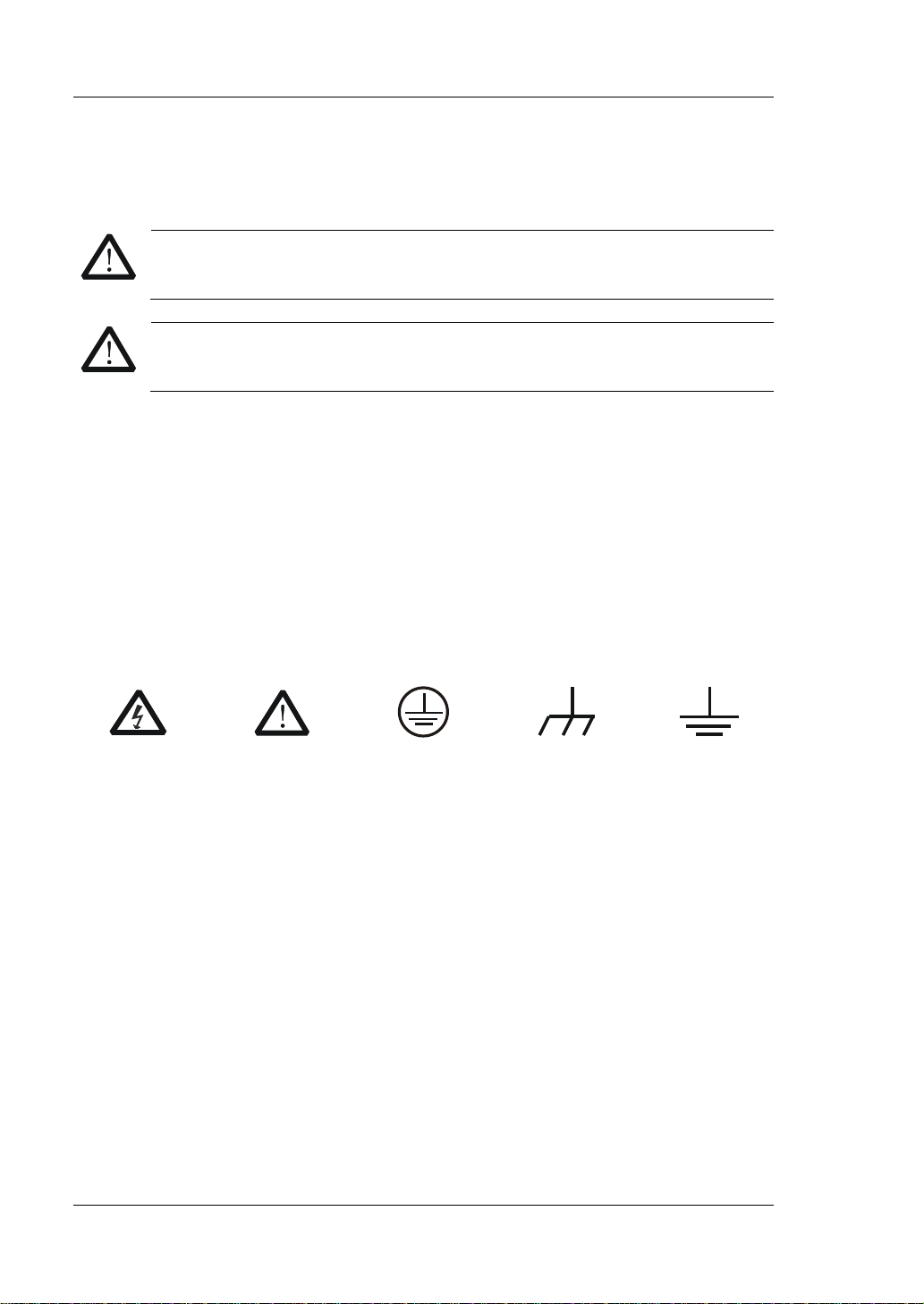
Safety Notices and Symbols
Safety Notic e s in this Manua l:
Indicates a potentially hazardous situation or practice which, if not
avoided, will result in serious injury or death.
CAUTION
Indicates a potentially hazardous situation or practice which, if not
avoided, could result in damage to the product or loss of important data.
Safety Terms on the Product:
result in injury or hazard immediately.
It calls attention to an operation, if not correctly performed, could
result in potential injury or hazard.
result in damage to the product or oth er devices connected to the
product.
Safety Symbols on the Product:
Voltage
Terminal
IV DP700 User’s Guide
Page 7

RIGOL
Allgemeine Sicherheits Informationen
Überprüfen Sie diefolgenden Sicherheitshinweise
sorgfältigumPersonenschädenoderSchäden am Gerätundan damit verbundenen
weiteren Gerätenzu vermeiden. Zur Vermeidung vonGefahren, nutzen S ie bitte das
Gerät nur so, wiein diesem Handbuchangegeben.
Um Feuer oder Verletzungen zu vermeiden, verwenden Sie ein
ordnungsgemäßes Netzkabel.
Verwenden Sie für dieses Gerät nur das für ihr Land zugelassene und genehmigte
Netzkabel.
Erden des Gerätes.
Das Gerät ist durch den Schutzleiter im Netzkabel geerdet. Um Gefahren durch
elektrischen Schlag zu vermeiden , ist es unerlässlich, die Er dung durchzufüh ren. Erst
dann dürfen weitere Ein- oder Aus gä nge verbun de n werden.
Anschluss einesTastkopfes.
Die Erdungsklemmen der Sonden sindauf dem gleichen Spannungspegel des
Instruments geerdet. SchließenSie die Erdungsklemmen an keine hohe Spannung
an.
Beachten Sie alle Anschlüsse.
Zur Vermeidung von Feuer oder Stromschlag, beachten Sie alle Bemerkungen und
Markierungen auf dem Instrument. Bef olgen Sie die Bedienun gsanleitung für weitere
Informationen, bevor Sie weitere Anschlüsse an das Instrument legen.
Verwenden Sie einen geeigneten Überspannungsschutz.
Stellen Sie sicher, daß keinerlei Überspannung (wie z.B. durch Gewitter verursacht)
das Gerät erreichen kann. Andernfallsbestehtfür den Anwender die
GefahreinesStromschlages.
Nicht ohne Abdeckung einschalten.
Betreiben Sie das Gerät nicht mit entfernten Gehäuse-Abdeckungen.
Betreiben Sie das Gerät nicht geöffnet.
Der Betrieb mit offenen oder entfernten Gehäuseteilen ist nicht zulässig. Nichts in
entsprechende Öffnungen stecken (Lüfter z.B.)
Passende Sicherung verwenden.
Setzen Sie nur die spezifikationsgemäßen Sicherungen ein.
Vermeiden Sie ungeschützte Verbindungen.
Berühren Sie keine unisolierten Verbindungen o der Baugrup pen, w ährend das Gerät
in Betrieb ist.
DP700 User’s Guide V
Page 8

RIGOL
Betreiben Sie das Gerät n ic h t i m Fe hlerfall.
Wenn Sie am Gerät einen Defekt vermuten, sorgen Sie dafür, bevor Sie das Gerät
wieder betreiben, dass eine Untersuchung durch RIGOL autorisiertem Personal
durchgeführt wird. Jedwede Wartung, Einstellarbeit en oder Austausch v on Teilen am
Gerät, sowie am Zubehör dürfen nu r von RIGOL au t orisiertem Personal
durchgeführt werd en.
Belüftung sicherstellen.
Unzureichende Belüftung kann zu Temperaturanstiegen und somit zu thermischen
Schäden am Gerät führen. Stellen Sie deswegen die Belüftung sicher und
kontrollieren regelmäßig Lüfter und Belüftungsöffnungen.
Nicht in feuc h te r Um g ebung betreiben.
Zur Vermeidun g von Kurzschluß im Geräteinne ren und Stromschlag betreiben Sie das
Gerät bitte niemals in feuchter Umgebung.
Nicht in explosiver Atmosphäre betreiben.
Zur Ve rm e idung von Personen- und Sachschäden ist es unumgängli ch, das Ger ät
ausschließlich fernab jedweder explosiven At mosphäre zu betreiben.
Geräteoberflächen sauber und trocken halten.
Um den Einfluß von Staub und Feuchtigkeit aus der Luft auszuschließen, halten Sie
bitte die Geräteoberflächen sauber und trocken.
Schutz gegen elektrostatische Entladung (ESD).
Sorgen Sie für eine elektrostatisch geschützte Umgebung, um somit Schäden und
Funktionsstörungen durch ESD zu vermeiden. Erden Sie vor dem Anschluß immer
Innen- und Außenleiter der V erbindungsleitung, um st atische Aufladung zu entladen.
Die richtige Verwendung desAkku.
Wenneine Batterieverwendet wird, vermeiden Sie hohe Temperaturen bzw. Feuer
ausgesetzt werden. Bewahren Sie es außerhalbder Reichweitevon Kindern auf.
Unsachgemäße Änderung derBatterie (Anmerkung: Lithium-Batterie) kann zu einer
Explosion führen. VerwendenSie nur von RIGOL angegebenenAkkus.
Sicherer Transport.
Transportieren Sie das Gerät sorgfältig (Verpackung!), um Schäden an
Bedienelementen, Anschlüssen und anderen Teilen zu vermeiden.
Vermeiden Sie das einprägen von Strom und Spannung an den
Testklemmen.
Das DP700 Power Supply kann hierdurch zerstört werd en, keine akive Last. Das
DP800A kann nur Strom und Spannun gen leifern.
VI DP700 User’s Guide
Page 9
RIGOL
WARNING
DANGER
weist auf eine Verletzung ode r Gefäh r dun g hin, die sof ort
WARNING
CAUTION
weist auf eine Verletzun g ode r Gefährdung hin und bedeutet, dass
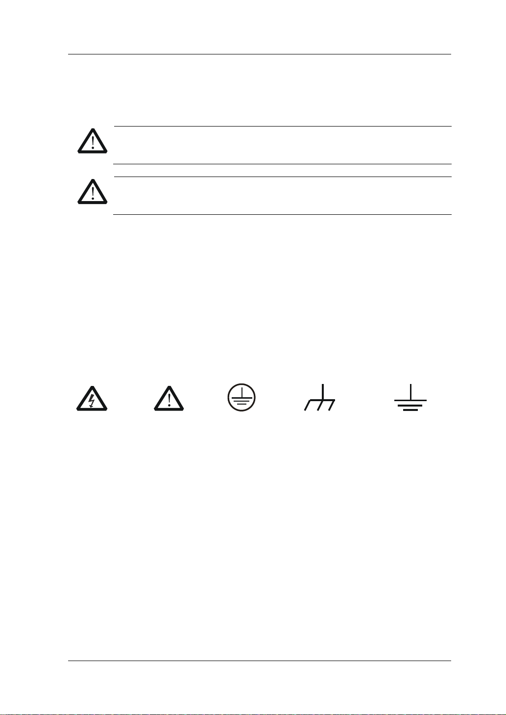
Sicherheits Begriffe und Symbole
Begriffe in diesem Guide:
Die Kennzeichnung WARNING beschreibt Gefahren q uell en die leibliche
Schäden oder den Tod von Personen zur Folge haben können.
CAUTION
Die Kennzeichnung Caution (Vorsicht) beschreibt Gefahrenquellen die
Schäden am Gerät hervorrufen können.
Begriffe auf dem Produkt:
geschehen kann.
weist auf eine Verletzung oder Gefäh rdung hin, die möglicherweise
nicht sofort geschehen.
eine mögliche Beschädigung des Instruments oder anderer
Gegenstände auftreten kann.
Symbole auf dem Produkt:
Gefährliche
Spannung
SicherheitsHinweis
Schutz-erde Gehäusemasse Erde
DP700 User’s Guide VII
Page 10
RIGOL
CAUTION
WARNING
Care and Cleaning
Care
Do not store or leave the instrument where it may be exposed to direct sunlight for
long periods of time.
Cleaning
Clean the instrument regularly according to its operating conditions.
1. Disconnect the instrument from all power sources.
2. Clean the external surfaces of the instrument with a soft cloth dampened with
mild detergent or water. When cleaning the LCD , take care to av oid sca rifying it .
To avoid damage to the instrument, do not expose it to caustic liquids.
To avoid short-circuit resulting from moist ure or personal injuries, ensure
that the instrument is completely dry before connecting it to the power
supply.
Environmental Consideratio ns
The following symbol indicates that this product complies with the WEEE Directive
2002/96/EC.
Product End-of-Life Handling
The equipment may contain substances that could b e harmf ul to t he e nvi ronm ent or
human health. To avoid the release of such substances into the environment and
avoid harm to human health, we recommend you to recycle this product
appropriately to ensure that most materials are reused or recycled properly. Please
contact your local authorities for disposal or recycling information.
VIII DP700 User’s Guide
Page 11
RIGOL
DP700 User’s Guide IX
Page 12

RIGOL
DP700 Series Overview
DP700 series power supply is a type of affordable programmable linear DC power
supply with high performance. With superb performance specifications, pure and
reliable output, and clear user i nterface, the DP700 series s upports timing out put and
trigger function, and provides a remote communication interface, enabling you to
meet your diversified test requirements .
Main Features:
DP711: single output, 30 V/5 A, total power up to 150 W
DP712: single output, 50 V/3 A, total power up to 150 W
Low ripple and noise:
DP711: <500 uVrms/3 mVpp, <2 mArms
DP712: <500 uVrms/4 mVpp, <2 mArms
Excellent load and line regulation rate: <0.01% + 2 mV; <0.01% + 2 mA
Transient response time: <50 μs
1 mV/1 mA resolution (optional)
Sound overvoltage/overcurrent/overtemperature protection, with the response
time for the overvoltage protection less than 10 ms
External trigger function supported, enabling synchronous output for multiple
devices
Timing output supported (10 ms to 99999 s) for up to 2,048 groups
3.5-inch TFT-LCD; compact and elegant; easy to use
Front panel locking and any specified key locking supported
RS232 interface communicatio n s upported
X DP700 User’s Guide
Page 13
RIGOL
Tip
RIGOL
Document Overview
Chapter 1 Quick Start
This chapter introduces so me basic information that y ou should know when yo u use
the DP700 series power supply for the first time. It contains the following contents:
out-of-box inspection method, the appearance and dimensions of the instrument,
descriptions of the front/r ear panel, how t o connect the inst rument t o the A C power,
how to carry out the power-on inspection, how to replace the fuse, a brief
introduction about the user interface, and how to set the parameters.
Chapter 2 Front Panel Operations
This chapter introduces what functions can be realized through the front panel
operations and the operation methods.
Chapter 3 Remote Control
This chapter introduces how to remotely control the instrument.
Chapter 4 Troubleshooting
This chapter introduces the possible failures and solutions in using the DP700 series
power supply.
Chapter 5 Specifications
This chapter lists the specifications of the DP700 series power supply.
Chapter 6 Appendix
This chapter provides order information and warranty information of the DP700
series power supply .
Index
This chapter provides keyword sea rch informat ion, enabling yo u to quickly locat e the
desired information.
For the latest version of this manual, download it from the official website of
(www.rigol.com).
Format Conventions in this Manual
Key
(1) The key on the front panel is denoted by the format of “Key Name (Bold) + Text
Box” in the manual. For example, On/Off denotes the "On/Off" key.
(2) Use the screen shot to indicate the key. For example, denotes the Power
key.
DP700 User’s Guide XI
Page 14

RIGOL
DP712
1
50 V/3 A
Content Con v entions in th is Ma n ual
DP700 series programmable linear DC power supply includes the following models.
Unless otherwise specified, this manual takes DP711 as an example to illustrate the
functions and operation methods of the DP700 series.
Model No. of Channels Output Voltage/Current
DP711 1 30 V/5 A
XII DP700 User’s Guide
Page 15

Contents RIGOL
Contents
Guaranty and Declaration ......................................................................... I
Safety Requirement ................................................................................ II
General Safety Summary ........................................................................... II
Safety Not ices and Symbol s ...................................................................... IV
Allgemeine Sicherheits Informationen ......................................................... V
Sicherheits Begriffe und Symbole ............................................................. VII
Care and Cleaning ................................................................................. VIII
Environmental Considerations ................................................................. VIII
DP700 Series Overview ............................................................................ X
Document Overview ............................................................................... XI
Chapter 1 Quic k S tart ......................................................................... 1-1
General Inspection ................................................................................ 1-2
Appearance and Dime nsions ................................................................... 1-3
Front Panel ........................................................................................... 1-4
Rear Panel ........................................................................................... 1-10
User Interface ...................................................................................... 1-12
Power-on Inspection ............................................................................. 1-14
Fuse Replacement ................................................................................ 1-17
Built-in Help Information ....................................................................... 1-17
Parameter Setting Method ..................................................................... 1-18
Chapter 2 Front Panel Operations ...................................................... 2-1
Constant Voltage Output ........................................................................ 2-2
Constant Current Output ........................................................................ 2-5
Power Supply in Series and Pa r alle l Co nnection ........................................ 2-8
Power Supply in Series Connection ................................................... 2-8
Power Supply in Pa r alle l C onnection .................................................. 2-9
Timer .................................................................................................. 2-10
Set Timer Parameters ..................................................................... 2-11
Enable the Timing Output ............................................................... 2-14
Trigger ................................................................................................ 2-16
Trigger Input ................................................................................. 2-16
Trigger Output ............................................................................... 2-17
Synchronous Output ....................................................................... 2-17
Store and Recall ................................................................................... 2-20
Manage Files ................................................................................. 2-21
Restore Default Settings ................................................................. 2-24
Clear All Saved Files ....................................................................... 2-25
System Utility Function ......................................................................... 2-26
System Setting .............................................................................. 2-27
RS232 Interface Setting .................................................................. 2-30
DP700 User’s Guide XIII
Page 16

RIGOL Contents
System Information ....................................................................... 2-32
Test and Calibration ....................................................................... 2-33
Option Co nf iguration ...................................................................... 2-35
Remote Locking ................................................................................... 2-37
Front Panel Locking ....................................................................... 2-37
Key Locking .................................................................................. 2-38
Chapter 3 Remote Control ................................................................. 3-1
Chapter 4 Troubleshooting ................................................................ 4-1
Chapter 5 Specifications .................................................................... 5-1
Chapter 6 Appendix ........................................................................... 6-1
Appendix A: Order Information ................................................................ 6-1
Append i x B: Warranty ............................................................................. 6-2
Index ........................................................................................................ 1
XIV DP700 User’s Guide
Page 17

Chapter 1 Quick Start RIGOL
Chapter 1 Quick Start
Contents in this chapter:
General Inspection
Appearance and Dime nsions
Front Panel
Rear Panel
User Interface
Power-on Inspection
Fuse Replacement
Built-in Help Information
Parameter Setting Method
DP700 User’s Guide 1-1
Page 18

RIGOL Chapter 1 Quick Start
General Inspection
1. Inspect the packaging
If the packa gi ng has be en da m age d, do n ot dis po se t he da m age d pac ka gin g o r
cushioning materials until the shipment has been che cked for completeness an d
has passed both electrical and mechanical tests.
The consigner or carrier shall be liable for the damage to the instrument
resulting from shipment. RIGOL would not be responsible for free
maintenance/rework or replacement of the instrument.
2. Inspect the instrument
In case of any mechanical damage, missing parts, or failure in passing the
electrical and mechanical tests, contact your RIGOL sales representative.
3. Check the accessories
Please check the accessories according to the packing lists. If the accessories
are damaged or incomplet e , pl e a s e contact your RIGOL sales representative.
1-2 DP700 User’s Guide
Page 19
Chapter 1 Quick Start RIGOL
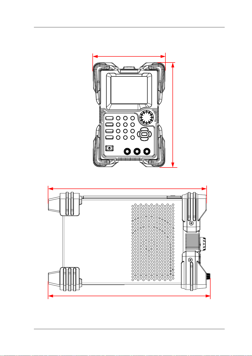
324
331.7
140
Appearance and Dimensions
202
Figure 1-1 Front View Unit: mm
Figure 1-2 Side View Unit: mm
DP700 User’s Guide 1-3
Page 20
RIGOL Chapter 1 Quick Start
V
mV
mA A
+
POWER
ON OFF
30V/5A
Number
1 2 3
4 5 6
7 8 9
Memory
System
OK
0
System
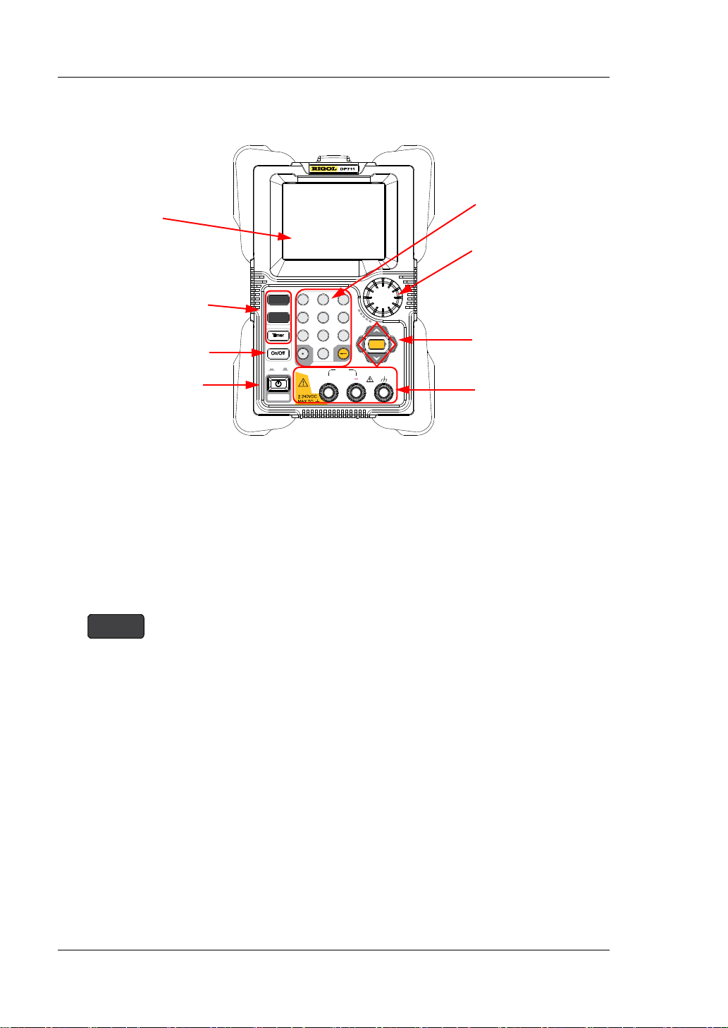
1. LCD
4. Power Key
Front Panel
8. Num Keys and
Return Key
7. K nob
2. Function Keys
6. Arrow Keys and
3. Output On/Off Key
Figure 1-3 Front Panel
1. LCD
3.5-inch TFT-LCD. It is use d to display the p arameter setting, output status, hel p
information, prompt message, etc.
2. Functi on Keys
2.1 System utility function key
Confirmation Key
5. Output
Terminals
1-4 DP700 User’s Guide
(1) System setting
Set the system language, power-on setting, and
brightness; turn on or off the beeper and screen saver;
enable the trigger input and trigger output.
(2) RS232 interface setting
Set baud rate and parity; view stop bit and data bit.
(3) System information
View the device model, serial number, and software
version.
(4) Test and calibration
View the test information: fan state.
View the auto calibration information: the auto
calibration status and the last auto calibration time.
Perform manual cali bration f or v oltage DAC calibrat ion,
Page 21
Chapter 1 Quick Start RIGOL
current DAC calibration, voltage ADC calibration,
Memory
current ADC calibration, and OVP calibration.
(5) Option configuration
View the installation status of the options, such as
Trigger, Timer, and High Resolution.
Install the options. For the installation methods, refer
to "Option Configuration".
2.2 Sto ring and recalling operation key
(1) Restore the instrument settings to defaults.
For default settings, refer to Table 2-3.
(2) Clear all saved files.
Clear all saved state files and timer files.
(3) Store, recall, or delete files.
The DP700 series can store up to 10 state files and 2 timer
files.
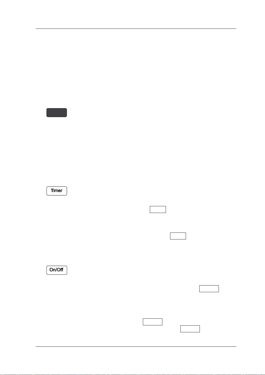
2.3 Timer key
(1) Set parameters f or timer: the n umber of output grou ps, the
number of cycles, trigger mode, end state, output voltage,
output current, and duration t ime.
Note: When you press Timer to ente r the timer interface,
the channel output is automatically disabled.
(2) Close the timer and return to the main interface.
During the timing output, press Timer and select "YES" to
close the timer and return to the main interface.
3. Output On/Off Key
(1) Enable or disable the channel output.
In the main i nterfa ce or othe r fu nction inte rfaces (in cluding
the system utility function interface, store and recall
interface; excluding the timer interface) , the On/Off key is
used to enable/disable the channel output.
(2) Enable or disable the timing output.
In the timer interface, after setting the parameters for
DP700 User’s Guide 1-5
the timer, press On/Off to enable the timing output.
During the timing output, p ress On/Off to disable the
Page 22
RIGOL Chapter 1 Quick Start
On/Off
+
30V/5A
(1) (2)
timing output. When you press
again, the
system will start to make output from the first group of
parameters.
4. Power Key
Turn on or off the instrument.
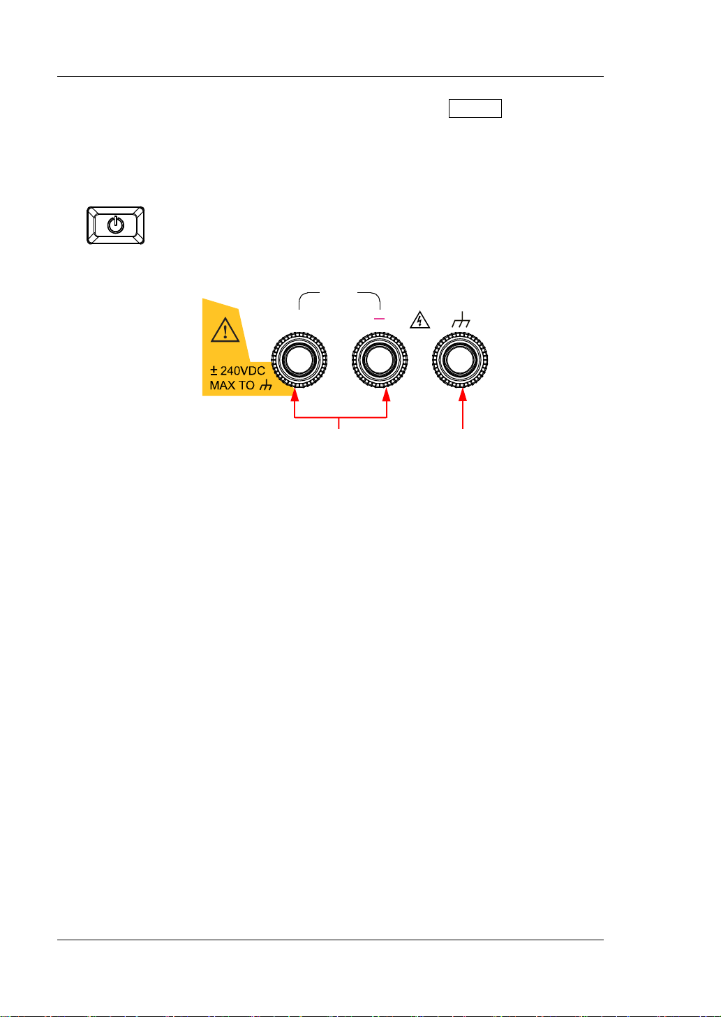
5. Output Terminals
(1) Channel output terminals: connect with the load, which are used to output
the voltage and current.
Note: Connect the positive terminal of the load with the (+) terminal of the
channel output and connect the negative terminal of the load with the (-)
terminal of the channel output.
(2) Ground terminal: connects with the instrument chassis and ground lead
(power cord ground termina l ), which is in the grounded state.
Note: The voltage to ground of any channel output terminal (+ or -) cannot
exceed ±240 Vdc.
1-6 DP700 User’s Guide
Page 23
Chapter 1 Quick Start RIGOL
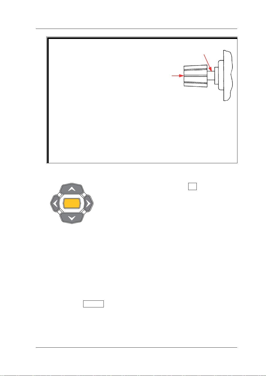
Connection Methods for the Output
V
mV
mA A
OK
Terminals:
Method 1:
Connect the test lead to Position A of the
output terminal.
Method 2:
Rotate the outer nut of the output terminal
counterclockwise and connect the test lead to
Position B of the output terminal; then, rotate
the outer nut of the output terminal clockwise
and fasten it firmly.
The second connection met hod can a voi d the
error arising from the resistance of the output
terminal. Method 2 is recommended when
the output current of the channel is relatively
greater.
6. Arrow Keys and Confirmation Key
Note: Pressing arrow keys or OK in different
interfaces can produce different operation results.
Here introduces their common usage. As for their
other functions and usages, refer to the detailed
introduction described in later sections of the
manual. Y ou can also refer to the help informatio n
at the bottom of the instrument interface.
6.1 Arrow keys (Up/Down/Left/Right key)
(1) Switch the parameter focus.
B
A
(2) Move the cursor.
(3) Switch the parameters or parameter values.
(4) Select the voltage/current unit.
Press the Up/Down arrow key to se lect V /mV as the voltage unit; p ress
the Left/Right arrow key to select mA/A as the current unit.
(5) Switch the tab.
Press System to enter the system utility function interface, and press
the Left/Right arrow key to select different tabs.
DP700 User’s Guide 1-7
Page 24
RIGOL Chapter 1 Quick Start
OK
6.2 Confirmation key
(1) Confirm the currently selected item.
(2) Enable/disable the specified function, such as overvoltage
protection (OVP) and overcurrent protection (OCP).
(3) Select the default voltage unit (V) and the default current
unit (A).
(4) Control the timing output.
When the trigger mode of the timer is set to "Single", one
single press on OK enables a single output ba s ed on one
group of timing parameters, until the instrument has
completed outputting operation for a specified number of
times (total number of output groups).
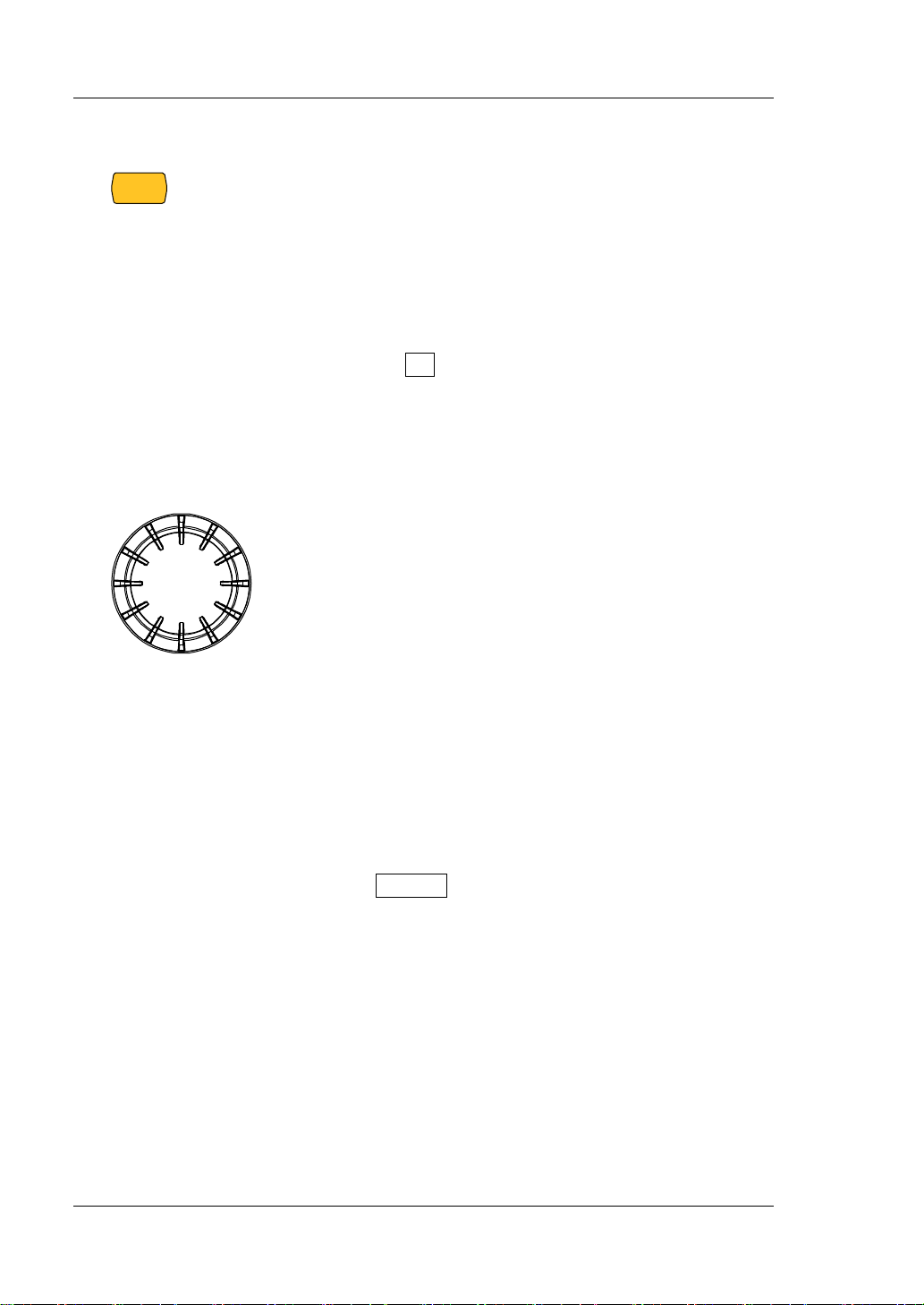
7. Knob
Note: Rotating the knob in different interfaces can
produce different operatio n result s. Here int roduces its
common usage. As for its other functions and usages,
refer to the detailed introduction described in later
sections of the manual. You can also refer to the help
information at the bottom of the instrument interface.
(1) Switch the parameter focus.
(2) Modify the value where the cursor stays.
(3) Switch the parameters or parameter values.
(4) Enter a negative measurement value.
During the manual calibration process, you can use
the knob to enter a negative measurement value.
(5) Switch the tab.
Press System to enter the system utility function
interface, and rotate the knob to select different tabs.
1-8 DP700 User’s Guide
Page 25
Chapter 1 Quick Start RIGOL
Number
1 2 3
4 5 6
7 8 9
0
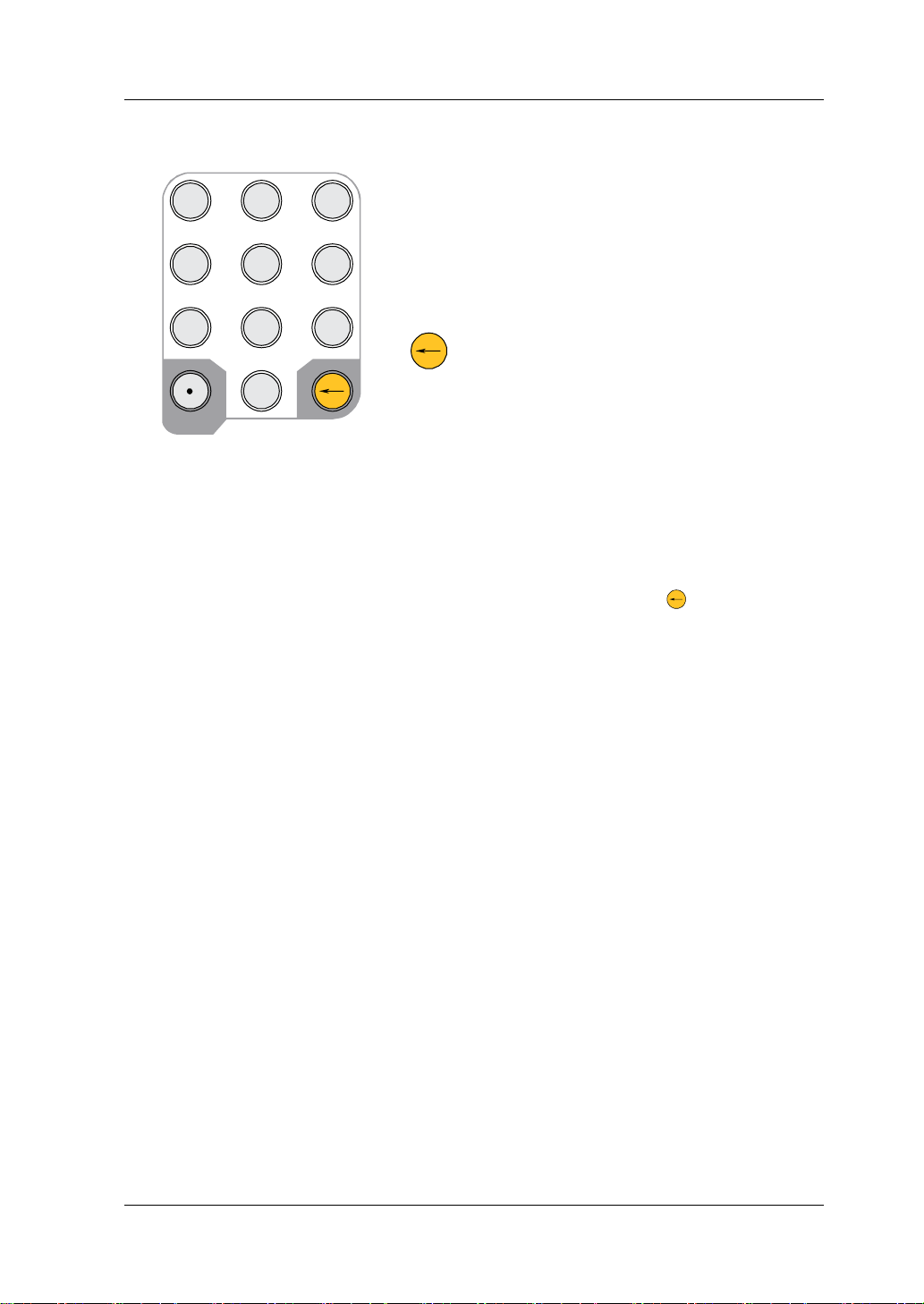
8. Num Keys and Return Key
8.1 Num keys
The num keys contain numbers (0-9) and a
dot. You can use the num keys to enter a
value.
8.2 Return key
(1) Delete the unwanted characters that
have been entered.
(2) Cancel the specified operation.
(3) Return to the local mode.
When the instrument is in the
remote mode, press this key to
return to the local mode.
(4) Enter the upgrade interface.
For the software upg r ade, when t he
welcome interface is displayed on
the screen, press
upgrade interface.
to enter the
DP700 User’s Guide 1-9
Page 26
RIGOL Chapter 1 Quick Start
ACSELECTOR
100Vac 120Vac 220Vac 240Vac
100V T5A
120V 250Vac
220V T2.5A
240V 250Vac
FUSE RATING
RIGOLTECHNOLOGIES,INC.
MADEINCHINA
6. Fuse Rating
3. RS232 Interface
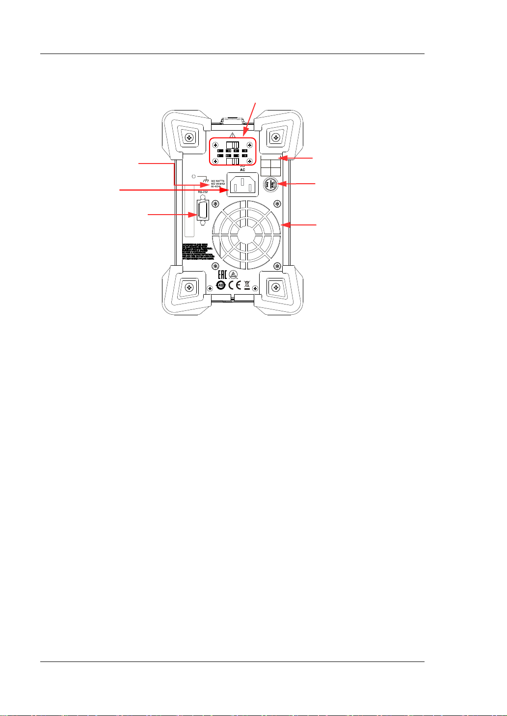
Rear Panel
1. Input Power
Requirement
2. AC Power
Supply Connector
Figure 1-4 Rear Panel
1. Input Power Requirement
The requirement for the power and frequency of the AC input power.
2. AC Power Supply Connector
Plug the specified power cord available in the accessories into the AC power
supply connector of the instrument, and then connect the instrument to the AC
power.
3. RS232 Interface
You can remotely control the DP700 series power supply via the interface.
Pin 7 and Pin 8 of the RS232 interface are not used in remote communication.
They are used in the trigger functio n. T ri gger is an o ptional function. If you want
to use the trigger function, order the trigger option based on the Order No.
available in "Appendix A: Order Information", an d then ins tall the o ption by
referring to "Option Configuration".
4. Air Outlet
Decrease the temperature inside the instrument to ensure its performance.
When you place the instru ment on the wo rkbench or install it i nto the ra ck, kee p
the air outlet from a distance of 10 cm to ensure adequate ventilation.
5. Fuse Cap
When leaving the factory, the instrument has installed a fuse that conforms to
7. AC Selector
5. Fuse Cap
4. Air Outlet
1-10 DP700 User’s Guide
Page 27
Chapter 1 Quick Start RIGOL
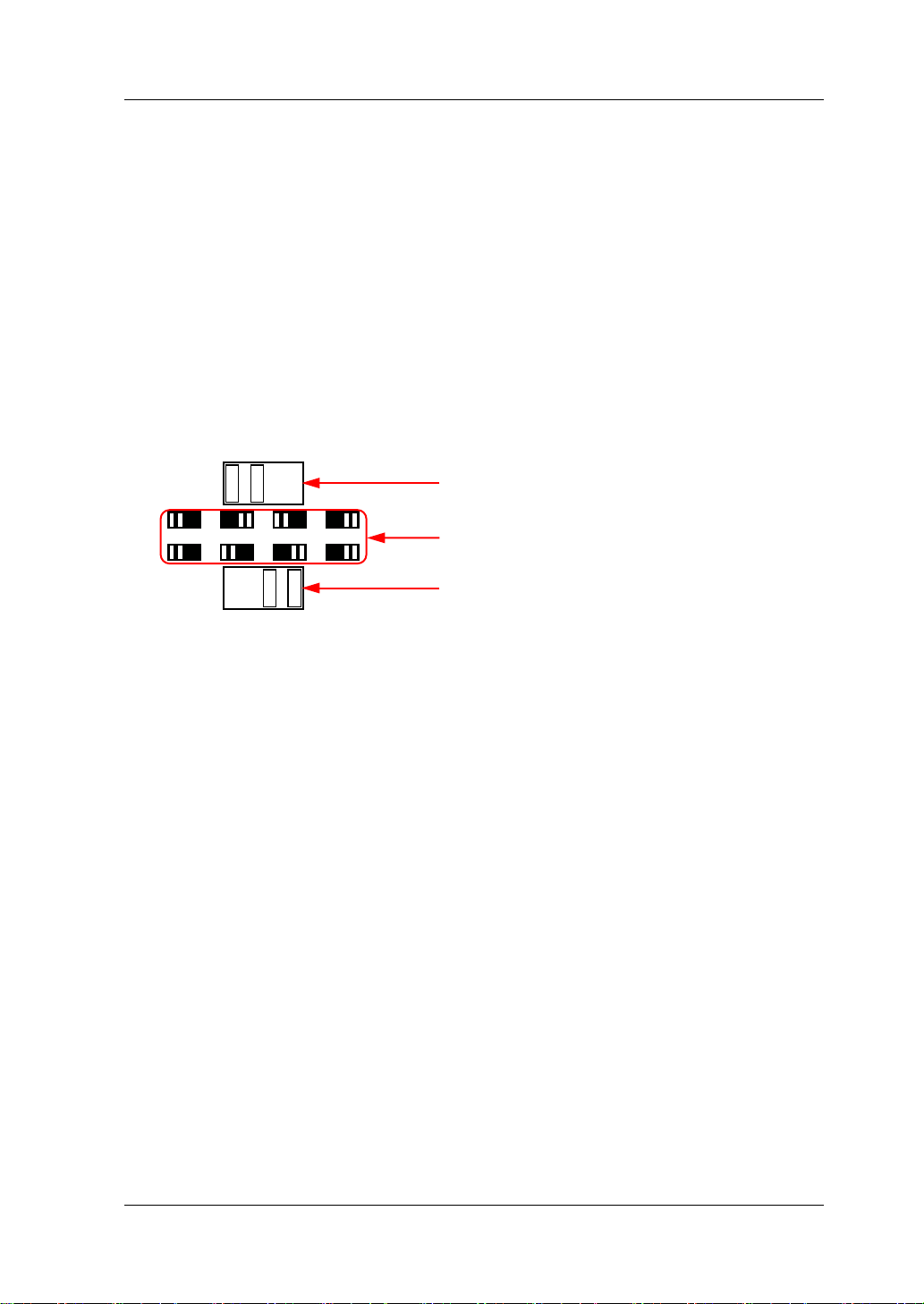
ACSELECTOR
100Vac 120Vac 220Vac 240Vac
Switch Lever (Top)
the standard of the destination country . For fuse replacement, refer to "Fuse
Replacement".
6. Fuse Rating
List the input voltage and its matched fuse specification.
7. AC Selector
Select the voltage rating that matches the actual AC input power. For the
matching relationship, refer to "Fuse Rating" on the rear panel or Table 1-2.
When the switch lever (including the top switch lever and the bottom switch
lever) is located at a different position, i t indicates th at a different voltage rating
is selected. For example, in the following figure, 220 Vac is selected.
Position of the switch lever and its
corresponding indicated voltage
Switch Lever (Bottom)
DP700 User’s Guide 1-11
Page 28

RIGOL Chapter 1 Quick Start
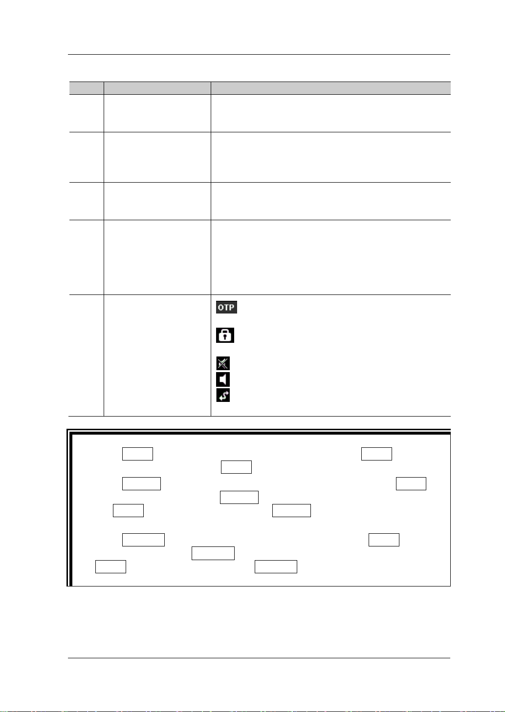
5. System Status Icons
1. Actual Output Mode
3. Help Information
User Interface
The user interface of the DP700 series power supply consists of the main interface
and the function interface. In the main interface, you can set and view the
information about the channel outp ut; in the f unction inter face, yo u can set and view
the information about the functions. When the instrument powers on, it enters the
main interface by default. This section mainly introduces the main interface of the
DP700 series power supply. The function interface will be introduced in "Front
Panel Operations".
2. Actual Output
Status
4. Output Setting
Figure 1-5 Main Interface
1-12 DP700 User’s Guide
Page 29
Chapter 1 Quick Start RIGOL
No.
Name
Description
Displays the actual output status of the channel in
Displays the help information of the current
Tip
Table 1-1 Main Interface Description
Displays the channel output mode in real time: CV
1 Actual Output Mode
(constant voltage), CC (constant current), or UR
(unregulated).
2 Actual Output Status
3 Help Information
4 Output Setting
5 System Status Icons
real time, including the actual output voltage (V),
the actual output cur rent (A), and the actual output
power (W).
interface in real time, including the interface
description, operation method, etc.
Sets the channel output parameters, including
output voltage, output cu rrent, the on/off status of
overvoltage pro t e ction, overvoltag e pro t e ction
setting value, the on/off sta t u s of overcurrent
protection, and overcurrent prot e ction setting
value.
: indicates that the overtemperature
protection occurred.
: indicates that the front panel has been
locked.
: indicates that the beeper is off.
: indicates that the beeper is on.
: indicates that the instrument is remotely
controlled.
Press Timer to enter the timer interface. At this time, the Timer key is
illuminated. Then, pressing Timer again will return to the main interface.
Press System to enter the system utility function interface. If the Timer key
is not illuminated, pressing System again will return to the main interface; if
the Timer key is illuminated, pressing System again will return to the timer
interface.
Press Memory to enter the store and recall interface. If the Timer key is not
illuminated, pressing Memory again will return to the main interface; if the
Timer key is illuminated, pressing Memory again will return to the timer
interface.
DP700 User’s Guide 1-13
Page 30
RIGOL Chapter 1 Quick Start
AC Input Power
AC Selector
100 Vac x (100 % ± 10%), 50 Hz t o 60 Hz
100 Vac
120 Vac x (100 % ± 10%), 50 Hz t o 60 Hz
120 Vac
WARNING
Power-on Inspection
The DP700 series power supply supports various specifications of AC input power.
When the DP700 series is connected with different power sources, the AC selector
setting on the rear panel of the ins trument is different, as shown in the table below.
Table 1-2 AC Input Power Specification and AC Selector Setting
220 Vac x (100 % ± 10%), 50 Hz to 60 Hz 220 Vac
240 Vac x (100% ± 10%) (max: 253 Vac), 50 Hz to 60 Hz 240 Vac
Please strictly follow the steps bel ow to c onnect the inst rument to t he power suppl y,
and perform the power-on inspection and output inspection.
1. Check the input power
Ensure that the AC power to be conne cted to the instrument conforms to the A C
input power requirement specified in Table 1-2.
2. Check the AC selector
Ensure that the AC selector set ting on the rear panel of the instrument matches
the actual AC input pow er (re fer t o Table 1-2).
3. Check the fuse
When leaving the factory, the instrument has installed a fuse that conforms to
the standard of the destination country. When the AC Selector is set to 100 Vac
or 120 V ac, Fuse T5A is us ed; when the AC Selector is set to 220 Vac or 240 Vac,
Fuse T2.5A is used.
4. Connect the AC power
Plug the specified power cord available in the accessories into the AC power
supply connector of the instrument, and then connect the instrument to the
properly grounded AC power.
To avoid electric shock, ensure that the instrument is correctly
grounded.
5. Power on the instrument
Press the Power key , and then the instrument is launched and begins to
perform the self-inspection. If the instrument passes the self-inspection, the
welcome interface is displayed; otherwise, self-inspection failure information
about corresponding items (including the analog board, OVP, OCP, fan, and
temperat ure) will be displayed.
1-14 DP700 User’s Guide
Page 31
Chapter 1 Quick Start RIGOL
Tip
Voltage
After powering off the inst rument , please wait for at least 2 s to power it on
again.
6. Perform the output check
Perform the output check to ensure that the power supply can output the rated
values and properly respond to the operations on the front panel.
Note: Before checking the current output, you should complete the check for
the voltage output first.
Check the voltage output: verify the basic voltage functions without a load.
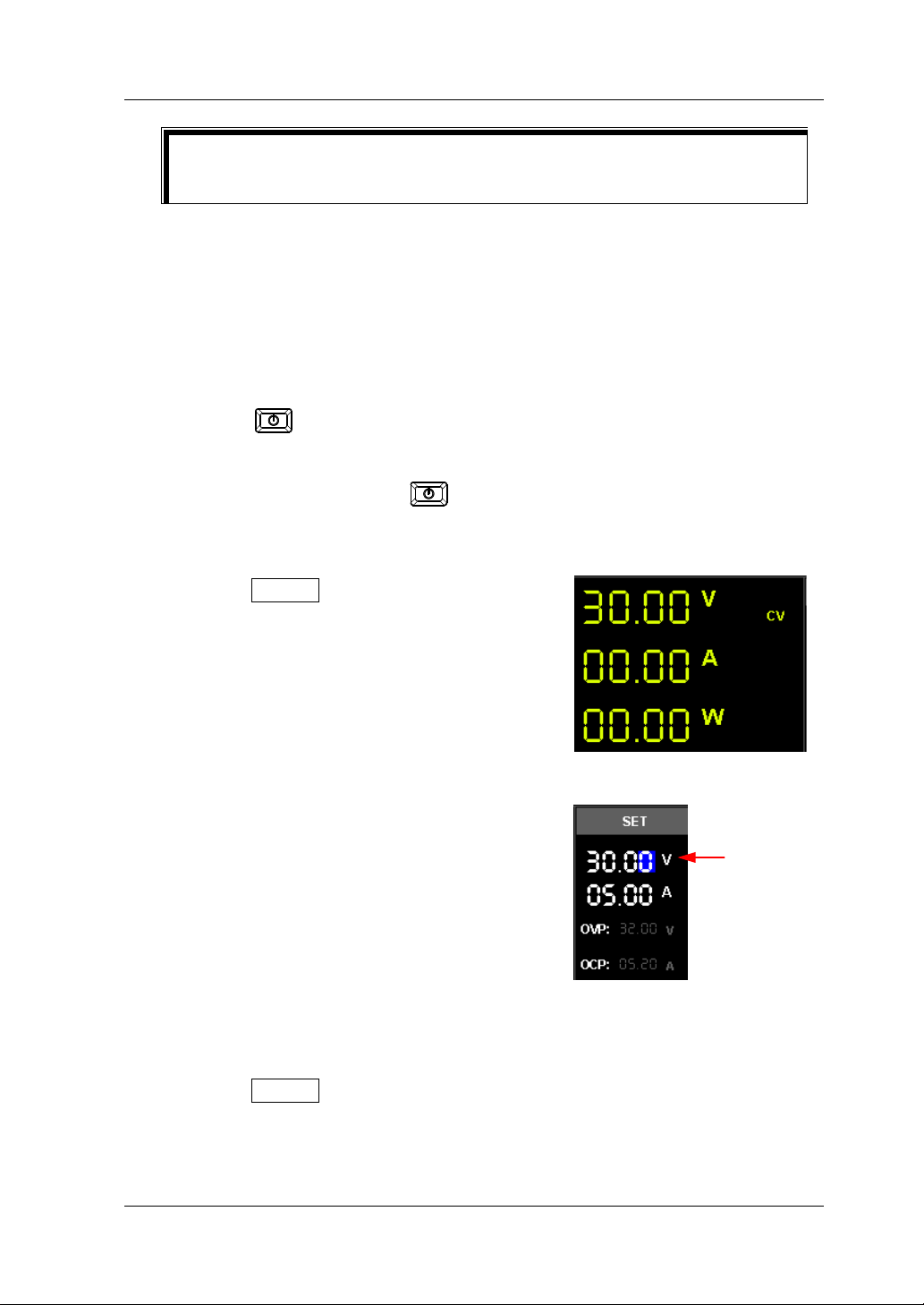
(1) Press
to turn off the instrument.
(2) Ensure that no load is connected to the channel output terminals on the
front panel. Then, press to power on the instrument, and check
whether the voltage between the positive terminal (+) and negative
terminal (-) of the channel output is 0 V.
(3) Press On/Off to turn on the channel
output. At this time, the actual output
status (actual output voltage (V), actual
output current (A), and actual output
power (W)) on the left section of the
interface is highlighted, and the actual
output mode (CV) is displayed.
(4) Set the output voltage to 0 V (For setting
methods, refer to the descriptions of the
help information at the bottom of the
interface or descriptions in "Parameter
Setting Meth o d ".), and check whether
the actual output voltage displayed on the
Setting Value
left section of the interface is approximately
0 V, the actual output current
approximately 0 A. Set the output voltage
to 30 V (max. rating value), and check
whether the actual output voltage is
approximately 30 V, the actual output
current approximat ely 0 A.
(5) Press On/Off to turn off the channel output.
Check the current output: verify the basic current functions with a short
across the power supply’s output.
DP700 User’s Guide 1-15
Page 32

RIGOL Chapter 1 Quick Start
(1) Connect a short across the positive te rminal (+) and negative terminal (-) of
the channel output with an insulated test lead (18 AWG), and then press
On/Off to tur n on the channel output. A t this time, the actual out put status
(actual output voltage (V), actual output current (A), and actual output
power (W)) on the left secti on of the interface is highlighted, and the actual
output mode is displa y ed . (Note that the actual output mode is determined
by the resistance of the test lead.)
(2) Set the output voltage to 2 V (For setting methods, refer to the descriptions
of the help information displayed at the bottom of the interface or refer to
the descriptions in "Para m et er Setting Method") and ensure the output
mode to be CC.
(3) Set the output current to 0 A (For setting
methods, refer to the descr iptions of the
help information at the bottom of the
interface or descriptions in "Parameter
Setting Meth o d ".), and check whether
Voltage Setting
Value
Current Setting
Value
the actual output current displayed on the
left section of the interface is approximately
0 A, the actual output voltage
approximately 0 V. Set the output current
to 5 A (max. rating value), and check
whether the actual output current is
approximately 5 A (the actual output
voltage indicates the voltage drop arising
from the test lead.)
(4) Press On/Off to turn off the channel output.
1-16 DP700 User’s Guide
Page 33

Chapter 1 Quick Start RIGOL
Input Voltage
Fuse
WARNING
To avoid personal injuries, cut off the p ower s up ply before replacing the
Slot
Fuse Replacement
The fuse specification is related to the actual input voltage, as shown in the table
below. You can also refer to the "Fuse Rating" on the rear panel of the instrument.
Table 1-3 Fuse Rating
100 Vac/120 Vac T5A 250Vac
220 Vac/240 Vac T2.5A 250Vac
When leaving the factory, the instrument has installed a fuse that conforms to the
standard of the destination country. If the fuse is required to be r eplaced , select a
fuse that matches the actual input voltage and perform the following steps.
1. Turn off the instrument and remove the power cord.
2. Insert a slotted screwdriver into the slot of the fuse cap
and push forward, then rotate 45° in the direction shown
on the fuse cap and take the fuse cap out.
3. Replace the fuse accordin g to the f use ratin g (refe r to the
"Fuse Rating" on the rear panel of the instrument or
Table 1-3).
4. Insert the fuse cap into the slot (pay attention to the
direction) and push forward, then rotate 45° in the
opposite direction to re-insert the fuse cap.
fuse; to avoid elect ric shock or fire, before connecting to the AC power,
select the voltage specification that matches the actual input voltage
and replace a proper fuse that conforms to the voltage specification.
Built-in Help Information
The help information of the currently displayed interface is displayed in real time at
the bottom of the interface, including interface description, how to select the
parameter, how to set the parameter, etc. Such information allows you to know the
instrument status and provides operation guidance for you.
DP700 User’s Guide 1-17
Page 34

RIGOL Chapter 1 Quick Start
Tip
Parameter Setting Method
Most parameters can be set through the f ront panel operations. The common setting
methods are listed below. The setting method for certain parameters is different
from the methods below , r efer to t he relev ant chapters of this manual for the fu rther
explanation.
Method 1 (Num Key):
1. Press the Up/Down arrow key to switch the parameter focus, such as the voltage
setting value, the number of output groups for timer, etc.
2. Enter a value by using the num key.
While entering a value, pre ss
3. When setting the voltage, press the Up arrow key or OK to set the voltage unit
to V; press the Down arrow key to set the voltage unit to mV.
When setting the current, press the Left a rrow key to set the current unit to mA ;
press the Right arrow key or OK to set the current unit to A.
When setting other parameters, press OK to confirm it.
Method 2 (Knob):
1. Press the Up/Down arrow key to switch the parameter fo cus, such as the voltage
setting value, the number of output groups for timer, etc.
2. Press the Left/Right arrow key to move the cursor to a desired position.
3. Rotate the knob to modify the value.
to delete the unwanted character if necessary .
The help information of the currently dis played interf ace is displayed in real time at
the bottom of the interface. You can also refer to the help information to set or
modify the parameters.
1-18 DP700 User’s Guide
Page 35

Chapter 2 Front Panel Operations RIGOL
Chapter 2 Front Panel Operations
Contents in this chapter:
Constant Voltage Output
Constant Current Output
Power Supply in Series and Pa r alle l Co nnection
Timer
Trigger
Store and Recall
System Utility Function
Remote Locking
DP700 User’s Guide 2-1
Page 36

RIGOL Chapter 2 Front Panel Operations
CAUTION
Current Setting Value
Constant Voltage Output
The DP700 series power supply can work in the constant voltage (CV) or constant
current (CC) mode
setting value, and the output current is determined by the load; whereas in the CC
mode, the output current equals to the current se tt ing v alue , an d the outp ut v oltage
is determined by the load. This section introduces the operation method for CV
output.
Operation Methods:
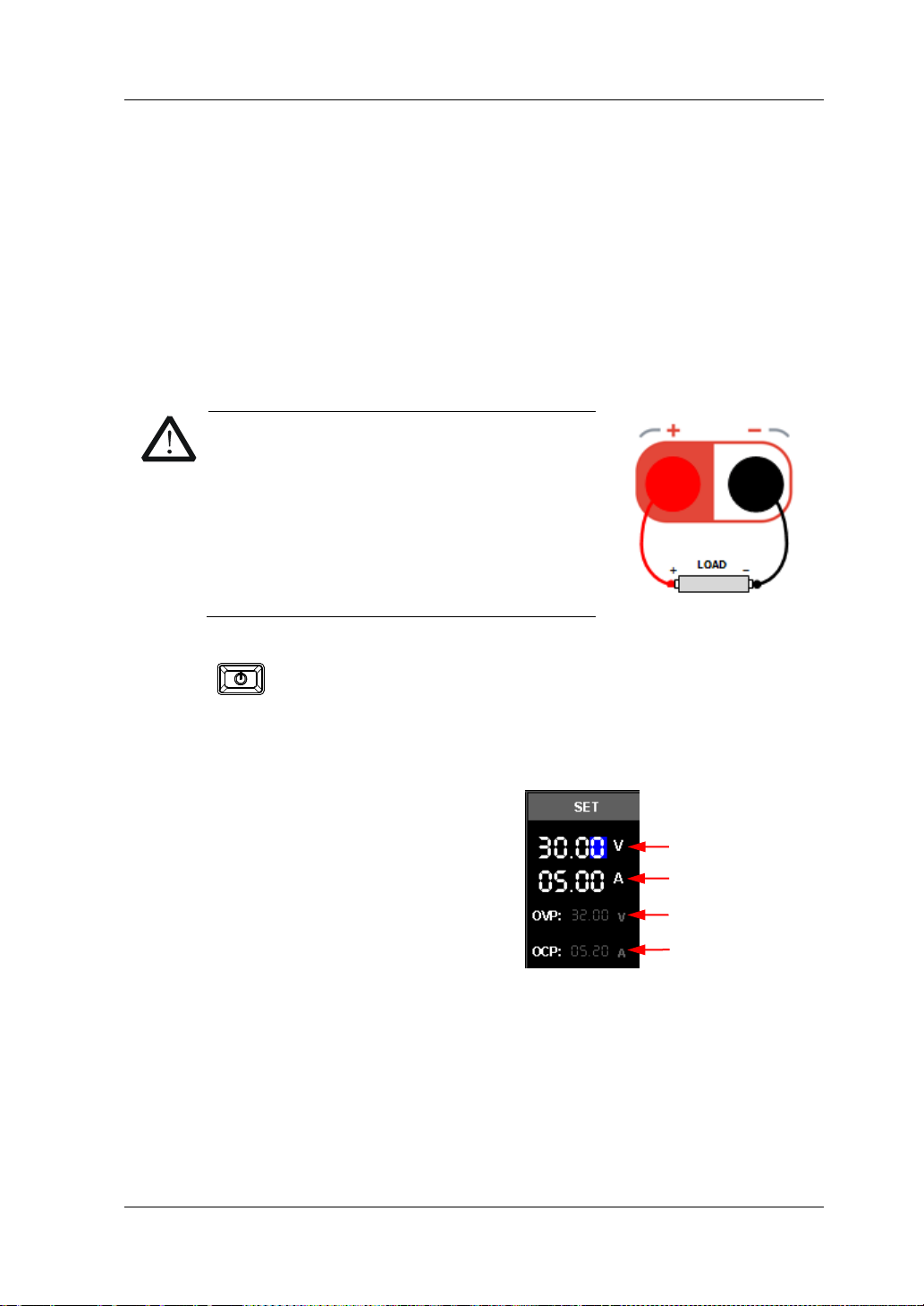
1. Connect the load with the channe l output ter minals
Turn off the instrument. Connect the load with the channel output terminals on
the front panel.
While making a connection, the positive
polarity of t he l oad should be connected to the
(+) terminal of the channel output, and the
negative polarity of the l oad to the (-) terminal
of the channel output. A misconnection with
the terminals may cause damage to the
instrument and the devices connected to it.
2. Turn on the instrument
Press
3. Set parameter s for the channel output
Set the output voltage
(1) In the main interface, press the
Up/Down arrow key to swit ch the
parameter focus to "Voltage Setting
Value".
(2) Use the num key or the knob to set a desired value for the output voltage.
[1]
. In the CV mode, the output voltage equals to the voltage
to turn on the instrument.
Voltage Setting Value
OVP Setting
OCP Setting
[1]
Note
power supply is unregulated (the channel output mode displayed as UR). In this mode, the output
is not predictable. The unregulated condition may be caused by the fact that the AC line voltage is
below the specifications. This condition may occur temporarily. For example, when the output
voltage is programmed for a large change, the output capacitor or a large capacitive load will
charge up until the current reaches the setting value. During the ramp-up of the output voltage, the
power supply will be in the unregulated mode. During the transition from CV to CC (e.g. transition
caused by a short circuit on the output), the unregulated condition may occur temporarily.
2-2 DP700 User’s Guide
: If the power supply should go into a mode of operation that is neither CV nor CC, the
Page 37

Chapter 2 Front Panel Operations RIGOL
For setting methods, refer to the descriptions of the help information
displayed at the bottom of the corresponding interface or refer to the
descriptions in "Parameter Setting Method".
Set the output current
(1) In the main interface, press the Up/Down arrow key to switch the
parameter focus to "Current Setting Value".
(2) Use the num key or the knob to set a desired value for the output current.
For setting methods, refer to the descriptions of the help information
displayed at the bottom of the corresponding interface or refer to the
descriptions in "Parameter Setting Method".
Set the overvoltage protection
(1) In the main interface, press the Up/Down arrow key to switch the
parameter focus to " OVP Setting".
(2) Press OK to enable/disable the overvoltage protection function.
When "OVP" is indicated in yellow, it indicates that the overvoltage
protection function is enabled; when "OVP" is in dicated in white, it indicates
that the overvoltage protection function is disabled.
(3) Use the num key or the knob to set a desired value for the overvoltage
protection. For setting methods, refer to the descriptions of the help
information displayed at the bottom of the cor re sponding inte rface or refer
to the descriptions in "Paramete r Setting Meth o d".
Set the overcurrent protection
(1) In the main interface, press the Up/Down arrow key to switch the
parameter focus to " OCP Setting".
(2) Press OK to enable/disable the overcurrent protection function.
When "OCP" is indicated in yellow, it indicates that the overcurrent
protection function is enabled; when "OCP" is i ndicated in white, it indi cates
that the overcurrent protection function is disabled.
(3) Use the num key or the knob to set a desired value for the overcurrent
protection. For setting methods, refer to the descriptions of the help
information displayed at the bottom of the cor re sponding inte rface or refer
to the descriptions in "Parame te r Setting Meth o d".
4. Turn on the channel output
Press On/Off to turn on the channel output. Then, the actual output voltage
(V), the actual output current (A), and the actual output power (W) are
highlighted; the actual output mode (CV) is displayed.
If the CC mode is displayed, please increase the current setting value
appropriately.
DP700 User’s Guide 2-3
Page 38

RIGOL Chapter 2 Front Panel Operations
WARNING
To avoid electric shock, ensure that t he load is connected to t he channel
CAUTION
Tip
In the CV mode, when the current of the load equals to the current setting value,
output terminals properly before you turn on the channel output.
When the fan works abnormally, the channel output is disabled. Then, a
message is displayed, "Fan abnormality, output disabled."
the power supply will automatically switch to the CC mode. At this time, the
output current equals to the current setting value, and the output voltage
decreases in proportions.
2-4 DP700 User’s Guide
Page 39
Chapter 2 Front Panel Operations RIGOL
CAUTION
OCP Setting
Voltage Setting Value
Current Setting Value
Constant Current Output
In the constant current (CC) mode, the output current equals to the current setting
value, and the output voltage is determined by the load. This section introduces the
operation method for CC output.
Operation Methods:
1. Connect the load with the channe l output ter minals
Turn off the instrument. Connect the load with the channel output terminals on
the front panel.
While making a connection, the positive
polarity of the load should be connected to
the (+) terminal of the channel output, and
the negative polarity of the load to the (-)
terminal of the channel output. A
misconnection with the terminals may cause
damage to the instrument and the devices
connected to it.
2. Turn on the instrument
Press to turn on the instrument.
3. Set parameter s for the channel output
Set the output voltage
(1) In the main interface, press the
Up/Down arrow key to swit ch the
parameter focus to "Voltage Setting
Value".
(2) Use the num key or the knob to set a
desired value for the output voltage.
OVP Setting
For setting methods, refer to the
descriptions of the help information
displayed at the bottom of the
correspondin g interfa ce or ref er to t he descriptions in "Parameter Se ttin g
Method".
Set the output current
(1) In the main interface, press the Up/Down arrow key to switch the
parameter focus to "Current Setting Value".
(2) Use the num key or the knob to set a desired value for the output current.
For setting methods, refer to the descriptions of the help information
DP700 User’s Guide 2-5
Page 40

RIGOL Chapter 2 Front Panel Operations
WARNING
When the fan works abnormally, the channel output is disabled. Then, a
displayed at the bottom of the corresponding interface or refer to the
descriptions in "Param eter Setting Method".
Set the overvoltage protection
(1) In the main interface, press the Up/Down arrow key to switch the
parameter focus to " OVP Setting".
(2) Press OK to enable/disable the overvoltage protection function.
When "OVP" is indicated in yellow, it indicates that the overvoltage
protection function is enabled; when "OVP" is in dicated in white, it indicates
that the overvoltage protection function is disabled.
(3) Use the num key or the knob to set a desired value for the overvoltage
protection. For setting methods, refer to the descriptions of the help
information displayed at the bottom of the cor re sponding interface or refer
to the descriptions in "Parame te r Setting Meth o d".
Set the overcurrent protection
(1) In the main interface, press the Up/Down arrow key to switch the
parameter focus to " OCP Setting".
(2) Press OK to enable/disable the overcurrent protection function.
When "OCP" is indicated in yellow, it indicates that the overcurrent
protection function is enabled; when "OCP" is indicated i n white, it in dicates
that the overcurrent protection function is disabled.
(3) Use the num key or the knob to set a desired value for the overcurrent
protection. For setting methods, refer to the descriptions of the help
information displayed at the bottom of the cor responding inte rface or refer
to the descriptions in "Parame te r Setting Meth o d".
4. Turn on the channel output
Press On/Off to turn on the channel output. Then, the actual output voltage
(V), the actual output current (A), and the actual output power (W) are
highlighted; the actual output mode (CC) is displayed.
If the CV mode is displayed, please increase the voltage setting value
appropriately.
To avoid electri c s hock, ensure that the load is connected to the cha nnel
output terminals properly before you turn on the channel output.
CAUTION
message is displayed, "Fan abnormality, output disabled."
2-6 DP700 User’s Guide
Page 41

Chapter 2 Front Panel Operations RIGOL
e CC mode, when the v olta ge of the load equals to the voltage se tting value,
Tip
In th
the power supply will automatically switch to the CV mode. At this time, the output
voltage equals to the voltage setting value, and the output current decreases in
proportions.
DP700 User’s Guide 2-7
Page 42
RIGOL Chapter 2 Front Panel Operations
Power Supply
Channel #1
-
+
Power Supply
Channel #2
-
+
V
1
V
2
V
L
R
Load
-
+
VL=V1+V
2
Power Supply in Series and Parallel Connection
The DP700 series power supply s upports series and pa rallel connections. Co nnecting
two or multiple power supplies in series/in parallel can provide higher
voltage/current.
In series and parallel connections, the parameter settings must comply with the
safety requirements.
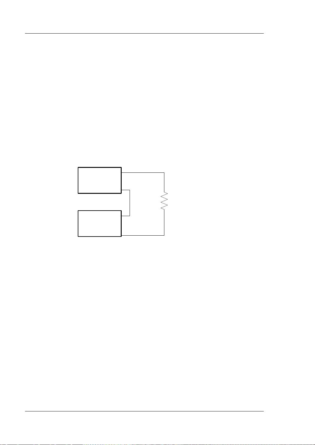
Power Supply in Series Connection
The output voltage of the power supplies that are connected in series is the sum of
the output voltages of all the channels. Take the series connection of tw o channels as
an example. The connection method is as shown in the figure below.
Operation Procedures:
1. Connect the load and the channel output terminals as shown in the figure above.
2. Turn on the instrument, and then refer to "Constant Voltage Output" to set
3. Enable the output of each channel.
2-8 DP700 User’s Guide
Pay attention to the polarity when making connections (the positive and
negative polarity of each channel is connected in alternating sequence).
the channel output parameters that comply with the safety requirements.
(1) Set a proper output voltage for each channel.
Note: Ensure that all the channels in series connection work in the CV
mode.
(2) Set the same output current values for all the channels.
Note: The current setting values for all the channels must be the same.
(3) Set the same overcurrent protection values for all the channels and enable
the overcurrent protection function for each channel.
Note: The overcurrent protection values for all the channels must be the
same.
Page 43
Chapter 2 Front Panel Operations RIGOL
Power Supply
Channel #1
-
+
Power Supply
Channel #2
-
+
I
1
I
L
R
Load
I
2
I
L=I1
+I
2
You can enable the exte rnal trigger fun ction to reali ze the synchro nous output
Tip
At this time, the voltage of the loa d i s t he s um of t he o utput volta ges of the tw o
channels (V
= V1 + V2).
L
Tip
1. When connecting the power supply in series, the total voltage in series
connection cannot exceed 240 V.
2.
for multiple power supplies. For details, refer to "Synchronous Output".
Power Supply in Parallel Connection
The output current of t he powe r supplies that are connected in parallel is the s um of
the output currents of all the cha nnels . Take the parallel connection of two channels
as an example. The connection method is as shown in the figure below.
Operation Procedures:
1. Connect the load and the channel output terminals as shown in the figure above.
Pay attenti on to the pola rity when making connecti ons. (The channels follow th e
"positive-positive" and "negative-negative" connection rule.)
2. T urn on the instrument, and then set proper output p arameters for each c hannel
by referring to "Constant Voltage Output".
Note: All channels can work either in the CV o r CC m ode, wh ich de pends on the
actual situation of the load.
3. Enable the output of each channel.
At this time, the current of the loa d is the su m of the out put currents of the tw o
channels (I
= I1 + I2).
L
You can enable the external trigger function to realize the synchronous output for
multiple power supplies. For details, refer to "Synchronous Output".
DP700 User’s Guide 2-9
Page 44

RIGOL Chapter 2 Front Panel Operations
Displays the actual output status of the ch a nnel in real
Displays the help information of the current interface,
1. Actual Output
3. Timer
Timing Parameter
2. Help Information
Timer
DP700 series power supply provides the timer function. When the timing output is
enabled, the instrument w ill configure the output volt ages and currents based on the
preset timer parameters. The edited timer parameters are allowed to be save d to the
internal non-volatile memory (NVM), and can be recalled if necessary.
Timer is an optional functi on. If y ou w ant t o use the timer f unctio n, o rder the option
based on the Order No. available in "Appendix A: Order Information", and then
install the option by referring to "Option Configuration
Press Timer to enter the timer interf ace (at this time , the Timer key is illumina ted),
as shown in the figure below.
".
Status and
Actual Output
Mode
Parameters
List
Figure 2-1 Timer Interface
Table 2-1 Timer Interface Description
No. Name Description
Actual Output
1
Status and Actual
Output Mode
2 Help Information
time, including the actual output voltage (V), the
actual output current (A), and the actual output pow er
(W). The actual output mode can be CV, CC, or UR.
including the interface description, operation method,
etc.
Includes the number of output groups, the number of
cycles, trigger mode, end state, and timing parameter
3 Timer Parameters
list. The timing pa ra meter li st consist s of the group ID,
the output voltage (V), the output current (A), and
duration t ime (s).
If you want to use the timer fu nction, set the ti mer pa ramete rs first and then e nable
the timing output.
2-10 DP700 User’s Guide
Page 45

Chapter 2 Front Panel Operations RIGOL
Tip
Set Timer Parameters
Operation Procedures:
1. Enter the timer inter f ace
Press Timer to enter the timer interface (at this time, the Timer ke y i s
illuminated).
Note: When you enter the timer interface, the channel output is automatically
disabled.
2. Set the number of output groups
"Outp Groups" indicates the number of groups of the preset voltage and current
values that the instrument outputs in each cycle. Its range is from 1 to 2048.
(1) Press the Up/Down arrow key to switch the parameter focus to "Outp
Groups".
(2) Use the num key or the knob to set a desired value for "Outp Groups". For
setting methods, refer to the descriptions of the hel p information displayed
at the bottom of the interface or refer to the descriptions in "Parameter
Setting Meth o d ".
3. Set the number of cycles
"Cycles" refers to the number of cycle times that the instrument perf orms timing
output according to the pr eset voltage an d current v alues. Its range is from 1 t o
99999. When the value is 1, you can use the knob to decrease the number
further, and then it will be switched to the infinite mode.
(1) Press the Up/Down arrow key to switch the parameter focus to "Cycles".
(2) Use the num key or the knob to set a desired v alue f or "Cycles". For setting
methods, refer to the description s of the help information displayed at the
bottom of the interface or ref e r t o t he des cri pti ons in "Parameter Setting
Method".
Total Number of Output Groups For the Timer = Outp Groups x Cycles
After the instrument has completed outputting operation for a specified
number of times (tot a l number of output groups), the timing output will
be terminated. At this time, the state of the instrument is determined by
the "end state" that you have set. Note: in the Infinite mode, "End
State" is invalid.
4. Select the trigger mode
"Trig Mode" refers to the timing output mode of the instrument.
Auto: when the timing output is enabled, the instrument automatically outputs
based on the parameter configuration of the timer.
Single: when the timing output is enabled, one single press on OK enables a
single output based on a group of timing par ameters, until the instrument has
DP700 User’s Guide 2-11
Page 46
RIGOL Chapter 2 Front Panel Operations
Tip
completed outputting operation for a specified number of times (total number of
output groups).
(1) Press the Up/Down arrow ke y to s witch t he pa ramet er f ocus t o "Trig Mode".
(2) Press the Left/Right arrow key or use the knob to select the desired trigger
mode.
5. Select the end state
"End State" refers to the state of the instrument after it has completed
outputting groups of voltage and current values for a specified number of times
(the total nu mber of out pu t grou ps) when the nu mber of cy cles is a finite value.
Outp Off: indicates that the output will be turned off automatically after the
output is completed.
Last: keeps the output state (voltage/current) of the last group after the output
is completed.
(1) Press the Up/Down arrow key to switch the parameter focus to "End State".
(2) Press the Left/Right arrow key or use the knob to select the desired end
state.
When "Cycles" is set to "Infinite", "End State" is invalid.
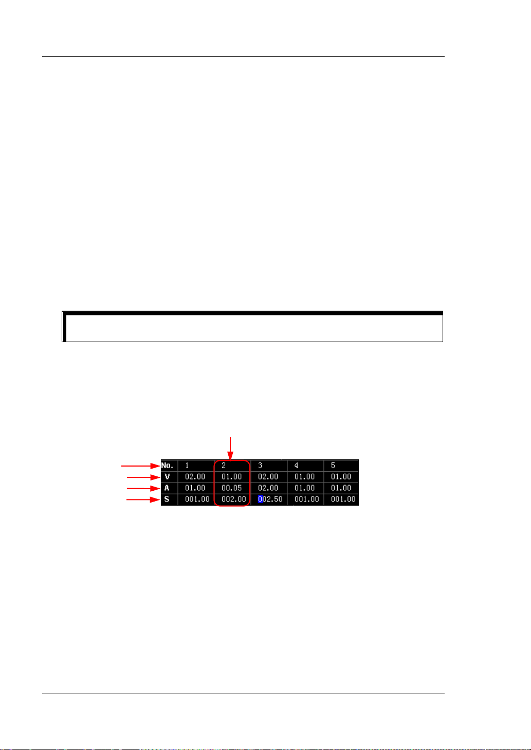
6. Edit the timing par ameter list
The timing parameters are used to control the output of the instrument. The
parameters consi st of the grou p ID , the output voltage, the output current, and
duration t ime. You can select a group ID first and then set the timing
parameters for the group.
One Group of Timing Parameters
Group ID
Output Voltage
Output Current
Duration Time
(1) Select a group ID
If the par ameter focu s is currently on the "Group ID" line, press the
Left/Right arrow key or us e the knob t o select the de sired group ID directly,
or use the num key to select the desired group ID. For setting methods,
refer to the descriptions of the help information displayed at the bottom of
the interface or refer to the descriptions in "Parameter Sett ing Method ".
If the parameter focus is currently not on the "G roup ID" line, first press the
Up/Down arrow key to switc h th e p arameter focus to the "Group ID" line,
and then select the desired group ID.
(2) Set the output voltage
2-12 DP700 User’s Guide
Page 47

Chapter 2 Front Panel Operations RIGOL
Press the Up/Down arrow key to switch the parameter focus to the
"Output Voltage" line.
Use the num key or the knob to set a desired value for the output
voltage (the default unit is V). For setting methods, refer to the
descriptions of the help information displayed at the bottom of the
interface or refer to the descriptions in "Parameter Setting
Method".
Note: when the current parameter focus is on the "Output Voltage" line,
press the Left or Right arrow key continuously to switch the parameter
focus to the "Output Volt age" of the neigh boring g ro up .
(3) Set the output current
Press the Up/Down arrow key to switch the parameter focus to the
"Output Current" line.
Use the num key or the knob to set a desired value for the output
current (the default unit is A). For the setting method, refer to the
description of the help information displayed at the bottom of the
interface or refe r t o the des cription in "P ara me ter Se ttin g Me th od ".
Note: when the current parameter focus is on the "Output Current" line,
press the Left or Right arrow key continuously to switch the parameter
focus to the "Output Current" of the neighborin g gr oup.
(4) Set the duration time
Press the Up/Down arrow key to switch the parameter focus to the
"Duration Time" line.
Use the num key or the knob to set a desired value for the duration
time (the default unit is s). For setting methods, refer to the
descriptions of the help information displayed at the bottom of the
interface or refer to the descriptions in "Parameter Setting
Method".
Note: when the current parameter focus is on the "Duration Time" line,
press the Left or Right arrow key continuously to switch the parameter
focus to the "Duration Time" of the neighboring group.
DP700 User’s Guide 2-13
Page 48

RIGOL Chapter 2 Front Panel Operations
Stor e and Recall Timer Files
Tip
The internal NVM of the DP700 se ries power su pply provi des two storage locations
for timer files (Tim er1 and Timer2). You can save the edited timing parameters to
the internal memory, or recall the stored timer files to set the timing parameters.
1. Store the timer files
Press Memory to enter the store and recall interface. To save the timer files,
refer to "Store Files".
2. Recall the timer files
Press Memory to enter the store and recall interface. To read the timer files,
refer to "Recall Files". After reading the files, the timing parameters will
make changes, but you c an still edit the timing parameters based on your
needs.
Enable the Timing Output
Enabling the timing output will modify the channel output values. Therefo re, before
enabling the timing output, ensure that the changes of the channel output will not
affect the devices that are connected to the power supply.
In the timer interface, after setting the parameters for the timer, press On/Off and
select "YES", then the timing output is executed based on the current setting.
The timer interface display s the actual out put status of the channel in real time ,
including the actual output voltage, the actual outpu t cu r rent, t he actual output
power, and the output mode.
In the timing parameter list, the groups that have been output are grayed out;
the current output group is indicated in yellow; and the groups that have not
been output are indicated in white.
When "Cycles" is a specified value, after the instrument has completed
outputting operation for a specified number of times (total number of output
groups), the timing output will be terminated. At this time, the state of the
instrument is determined by the "end state" that you have set.
When "Cycles" is set to "Infinite", the instrument makes consecutive outputs
based on the current timer parameter settings. At this time, the end state is
invalid.
Complete timer parameter settings before enabling the timing output. During the
timing output, the timer parameters are not allowed to be modified.
2-14 DP700 User’s Guide
Page 49

Chapter 2 Front Panel Operations RIGOL
During the timing output:
Press On/Off to disable the t iming output. When you press On/Off again, the
system will start to output from the first group.
Press Timer and select "YES" to close the timer and return to the main
interface.
DP700 User’s Guide 2-15
Page 50

RIGOL Chapter 2 Front Panel Operations
Trigger
DP700 series power supply provides the trigger function, including trigger input and
trigger output. Trigger input indicates that the external trigger input signal controls
the on/off status of the channel output. Tr igger output indicates that controlling the
on/off status of the channel output can ena ble the in strument to output the s pecified
signal. When multiple pow er supplies are in serial or parallel connection, enabling the
external trigger function can realize the synchronous output for multiple power
supplies.
Pin 8 of the RS232 interface on the rear panel is use d for trigger input, a nd Pin 7 for
trigger output.
Pin 7: TRIG_OUT
Pin 8: TRIG_IN
Trigger is an optional function. If you want to use the trigger function, order the
option based on the O rder No. av ailable in "Appendix A: Order Information", and
then install the option by referring to "Option Configuration".
Trigger Input
Pin 8 of the RS232 interface on the rear panel is used to receive the external t rigger
input signal. When it receives a high level sig nal (≥ 2.1 V, 10 mA), the channel output
will be turned on; when it receives a low level signal (≤0.7 V, 10 mA), the channel
output will be turned off.
Operation Procedures:
1. Turn off the instrument . Connect the exte rnal trig ger in put si gnal to P in 8 of th e
RS232 interface on the rear panel.
2. Connect the load with the channel output terminals on the fr ont panel.
3. Turn on the instrument. Press System to enter the system utility interface. By
default, the "Setting" tab is selected. Press the Up/Down arrow key to switch t he
parameter focus to "Trig In", and press the Left/Right arrow key or the knob to
enable the trigger input function.
2-16 DP700 User’s Guide
Page 51

Chapter 2 Front Panel Operations RIGOL
#2 #3
#1
Pin 7
Pin 8
Trigger Output
Pin 7 of the RS232 interface on the rear panel is used to output the trigger output
signal. When the channel output is turned on, the high l evel signal (≥2.1 V, 10 mA) is
output from Pin 7; when off, the low level signal (≤0.7 V, 10 mA) is output from Pin 7 .
Operation Procedures:
1. Turn off the instrument. Connect Pin 7 of the RS232 interface on the rear panel
to the signal receiving/display device.
2. Connect the load with the channel output terminals on the front panel.
3. Turn on the instrument. Press System to enter the system utility interface. By
default, the "Setting" tab is selected. Press the Up/Down arrow key to switch t he
parameter focus to "T rig Out", and press the Le ft/Rig ht arrow key or the kn ob to
enable the trigger output function.
Synchronous Output
When multiple power supplies are in serial or parallel connection, enabling the
external trigger function can realize the synchronous output for multiple power
supplies.
DP700 series power supply provides the following synchronous output modes:
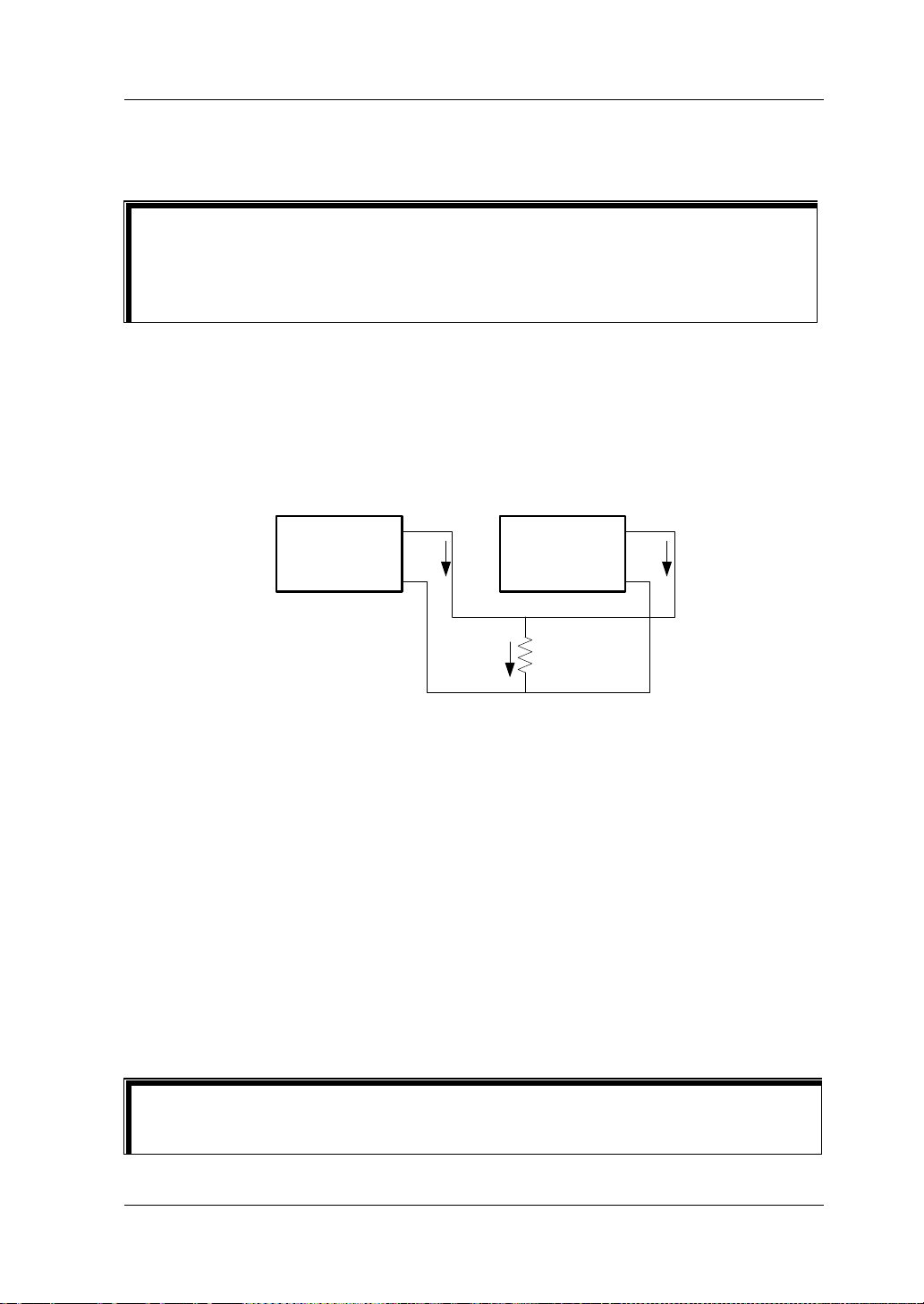
Mode 1:
Take the trigger output signal of one power supply (master device) as the trigger
input signal of the other power supplies (slave devices). In this case, you can press
On/Off on the powe r su pply (mast er de vice ) to s ynch ronou sly c ont rol th e out put o f
all the power supplies. The following example illustrates the operation steps on how
to synchronously control the other two power supplies through one power supply.
Operation Procedures:
1. Connect Pin 7 (trigger output sig nal) of the RS 232 interf ace on the rea r panel of
Power Supply 1 to Pin 8 (t rigger inp ut sig nal) of the RS232 inter face on the rear
panel of Power Supply 2 and 3, as shown in the figure below.
DP700 User’s Guide 2-17
Pin 8
Page 52

RIGOL Chapter 2 Front Panel Operations
#2
#3
#1
2. Enable the trigger output function of Power Supply 1; and enable the trigger
input function of Power Supply 2 and 3.
3. Press On/Off on Power Supply 1 to turn on its channel output. At this time,
As the trigger output function of P ower Supply 1 i s enabled, Power Supply 1
will output the trigger output signal (a high level signal, ≥2.1 V, 10 mA)
from Pin 7.
As the trigger input functions of Power Supply 2 and 3 have been enabled,
after Power Supply 2 and 3 receives trigger inpu t s ignal (i.e. trigger output
signals of Power Supply 1), the channel output will be turned on.
Similarly, when you press On/Off on Power Supply 1 to turn off its channel
output, the channel output of Power Supply 2 and 3 will also be turned off.
Now, the operation is complete. You can press On/Off on Power Sup ply 1 to
synchronously control the output of Power Supply 1, 2, and 3.
Mode 2:
Take the trigger output signal of one power supply as the trigger input signal of its
adjacent power supply in sequence. In this case, you can press On/Off on the fi rst
power supply to synchronously control the output of all the power supplies. The
following example illust rates the o peration ste ps on how t o synchronously control the
other two power supplies through one power supply.
Operation Procedures:
1. Connect Pin 7 (trigger output sig nal) of the RS 232 interf ace on the rea r panel of
Power Supply 1 to Pin 8 (t rigger inp ut sig nal) of the RS232 inter face on the rear
panel of Power Su pply 2, and connect Pin 7 (t rigger out put si gnal) of t he RS2 32
interface on the rear panel of Power Supply 2 to Pin 8 (trigger input signal) of
the RS232 interface on the rear panel of Power Supply 3, as shown in the figure
below.
Pin 7
Pin 7
Pin 8
Pin 8
2-18 DP700 User’s Guide
Page 53

Chapter 2 Front Panel Operations RIGOL
2. Enable the trigger output function of Power Supply 1; enable the trigger input
and output functions of Power Supply 2; enable the trigger input function of
Power Supply 3.
3. Press On/Off on Power Supply 1 to turn on its channel output. At this time,
As the trigger output function of Power Supply 1 has been enabled, Power
Supply 1 will output the trigger output signal (a high level signal, ≥2.1 V, 10
mA) from Pin 7.
As the trigger input function of Power Supply 2 has been enabled, after
Power Supply 2 receives the trigger input signal (i.e. the trigger output
signal of Power Supply 1), the channel output will be turned on.
As the trigger output function of Power Supply 2 has been enabled, when
the channel output of Power Supply 2 is turned on, Power Supply 2 will
output the trigger out put signal (a high level signal, ≥2.1 V, 10 mA) from Pin
7.
As the trigger input function of Power Supply 3 has been enabled, after
Power Supply 3 receives the trigger input signal (i.e. the trigger output
signal of Power Supply 2), the channel output will be turned on.
Similarly, when you press On/Off on Power Supply 1 to turn off its channel
output, the channel output of Power Supply 2 and 3 will also be turned off.
Now, the operation is complete. You can press On/Off on Power Sup ply 1 to
synchronously control the output of Power Supply 1, 2, and 3.
DP700 User’s Guide 2-19
Page 54

RIGOL Chapter 2 Front Panel Operations
No.
Name
Description
Restores the instrument settings to defaults
Store and Recall
DP700 series power supply allows you to save the instrument status or timer
parameters to the internal NVM, and recall them if necessary. Besides, you can
restore the instrument to default settings and clear the saved state files and timer
files.
Press Memory to enter the store and reca ll interface, as shown in the figure below .
Figure 2-2 Store and Recall Interface
Table 2-2 Store and Recall Interface Description
Indicates the storage location of the state
file. The state file is used to st ore the current
1 State1 to State10
2 Timer1/Timer2
3 Restore default setting
4 Clear all saved files
2-20 DP700 User’s Guide
state information of the instrument, in cluding
but not limited to parameter and system
status.
Indicates the storage location of the timer
file. The timer file is used to store timer
parameters, including the number of output
groups, the number of cycles, trigger mode,
end state, output voltage, output current,
and duration time.
(refer to Table 2-3).
Clears all saved state files and timer files in
the internal NVM.
Page 55

Chapter 2 Front Panel Operations RIGOL
Manage Files
The internal NVM of the DP700 series power supply provides ten storage locations for
state f i le s an d two for timer files. Therefore, you are allowed to save the current
status information of the i nstrument or its timer par ameters to the specified location,
and recall the saved files if necessary.
Store Files
The file name can contain lowercase let te rs (a-z) and numbers (0-9). The maximum
length of the file name is 11 characters.
Operation Procedures:
1. Specify a storage location
Press Memory to enter the store and recall interface, and then press the
Up/Down/Left/Right arrow key or use the kno b to sw itch the paramet er f ocus to
a desired storage location for state f il e (St ate 1 to State10 ) or a desired storage
location for timer file (Timer1 or Timer2).
2. Enter a file name
(1) Press OK and then the file management options are displayed at the
bottom of the interface. By default, "Save" is selected. (You can also press
the Left/Right arrow key or use the knob to select "Save".) Then press OK
to enter the file name input interface.
File Name Input Area Virtual Keypad
Figure 2-3 File Name Input Interface
(2) In the file name input interf ace, press the Up/Down /Left/Ri ght arrow k ey or
use the knob to select the desired characters on the virtual keypad, and
then press OK to enter the characters. The input characters are displayed
DP700 User’s Guide 2-21
Page 56

RIGOL Chapter 2 Front Panel Operations
Tip
in the "File Name Input Area". While entering a name, press to delete
the unwanted character if necessary.
3. Save a file
After inputting a file name, select "Save" on the virtual keypad and press OK to
save the file. After the file is saved, a message will be displa ye d, pr omptin g y ou
that you have saved the file.
If there is an existing file in the currently selected location, you can determine
whether to overwrite the existing file. Press the Left/Right arrow key to select
"YES" and press OK to overwri te t he existing saved file; select "NO" and press
OK to give up saving the file.
If you want to quit the saving operation, select "Exit" on the virtual keypad to give
up saving the file, and then press OK.
Recall Files
You a re allowed to recall all sa ved state files and timer files. After the files have been
read, the status information of the instrument or the timer parameters will make
changes accordingly.
Operation Procedures:
1. Press Memory to enter the store and recall interface, and then press the
Up/Down/Left/Right arrow key or use the kno b to sw itch the paramet er f ocus to
the storage location where the file to be recalled can be found.
2. Press OK and then press the Left/Right arrow key or use the knob to select
"Read" to read the saved file in the selected storage location. After the file
reading is complete, a message will be displayed, prompting you that the
reading process is complete.
If no sav ed file is found in the selected storage location, the "Read" key is
grayed out and disabled.
Delete Files
You are allowed to delete the saved state files and timer files.
Operation Procedures:
1. Press Memory to enter the store and recall interface, and then press the
Up/Down/Left/Right arrow key or use the kno b to sw itch the paramet er f ocus to
the storage location where files to be recalled can be found.
2-22 DP700 User’s Guide
Page 57

Chapter 2 Front Panel Operations RIGOL
2. Press OK and then press the Left/Right arrow key or use the knob to select
"Dele" to delete the saved file in the selected stora ge location. After deleting the
file, a message will be displayed, prompting you that the deleting process is
complete.
If no saved file is found in the selected storage location, the "Dele" key is grayed
out and disabled.
Note: The locked files are not allowed to be deleted (You can send the SCPI
command :MEMory[:STATe]:LOCK to lock the files. For details, refer to
Programming Guide
.)
DP700
DP700 User’s Guide 2-23
Page 58
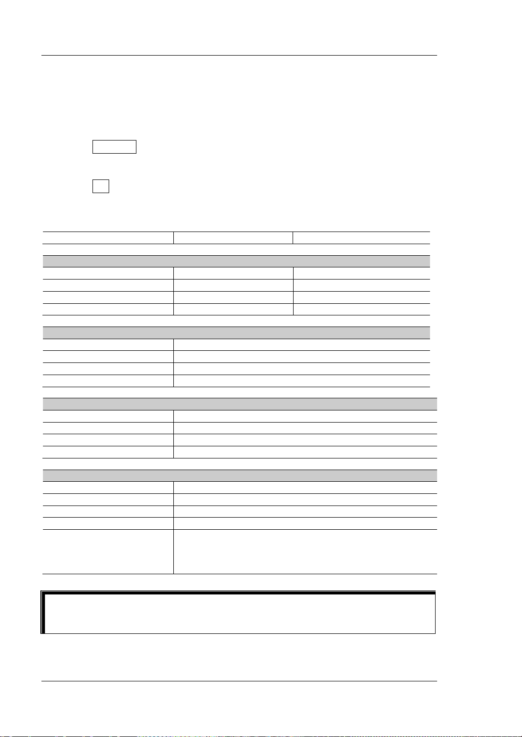
RIGOL Chapter 2 Front Panel Operations
Model
DP711
DP712
Channel Parameter
Timer
Number of Output Groups
1
Tip
Restore Default Settin gs
Restore the instrument settings to defaults if necessary, as shown in Table 2-3.
Operation Procedures:
1. Press Memory to enter the store and recall interface. By default, "Restore
defaults" is selected. You can also press the Up/Down/Left/Right arrow key or
use the knob to switch the parameter focus to "Restore defaults".
2. Press OK and select "YES" to restore the instrument settings to defaults, as
shown in Table 2-3.
Table 2-3 Default Settings
Voltage/Current Setting Value 0 V/5 A 0 V/3 A
OVP/OCP Value 32 V/5.3 A 53 V/3.2 A
OVP/OCP On/Off Off/Off Off/Off
Output On/Off Off Off
System Setting
Beeper On
Screen Saver Off
Trigger Input Off
Trigger Output Off
RS232 Interface Setting
Baud Rate 9600
Stop Bit 1
Data Bit 8
Parity None
Number of Cycles 1
Trigger Mode Auto
End State Output Off
Timing Parameter
When "power-on setting" is set to "Default", it indicates that the instru ment will
be restored to defaults once the instrument is powered on again.
2-24 DP700 User’s Guide
Group ID: 1
Output Voltage: 1 V
Output Current: 1 A
Duration Time: 1 s
Page 59

Chapter 2 Front Panel Operations RIGOL
Clear All Saved Files
You are allowed to clear all saved state files and timer files in the internal NVM.
Operation Procedures:
1. Press Memory to enter the store and recall interface, and then press the
Up/Down/Left/Right arrow key or use the knob to switch the par ameter f ocus to
"Clear all saved files".
2. Press OK and select "YES" to clear all saved state files and timer files.
DP700 User’s Guide 2-25
Page 60
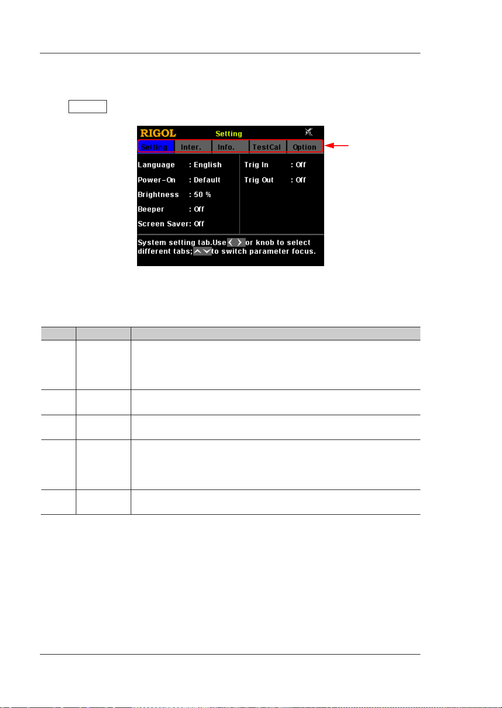
RIGOL Chapter 2 Front Panel Operations
No.
Name
Description
View device model, serial number, and software version.
Tabs
System Utility Function
Press System to enter the system utility function interface.
Figure 2-4 System Utility Function Interface
The following table list s names of diff erent tabs and their desc ripti ons. Y ou ca n view
the information contained in each tab and the parameters that can be set.
1 Setting
2 Inter.
3 Info.
4 TestCal
5 Option
System setting tab.
Select system language; select power-on setting; set screen
brightness; turn on/off t he beeper and screen saver; turn
on/off the trigger input or output.
RS232 interface tab.
Set baud rate and parity; view stop bit and data bit.
System information tab.
Test and calibration tab.
View the test information and auto calibration information;
perform manual calibration; and modify the calibration
password.
System option tab.
View the option installation information; install the options.
2-26 DP700 User’s Guide
Page 61
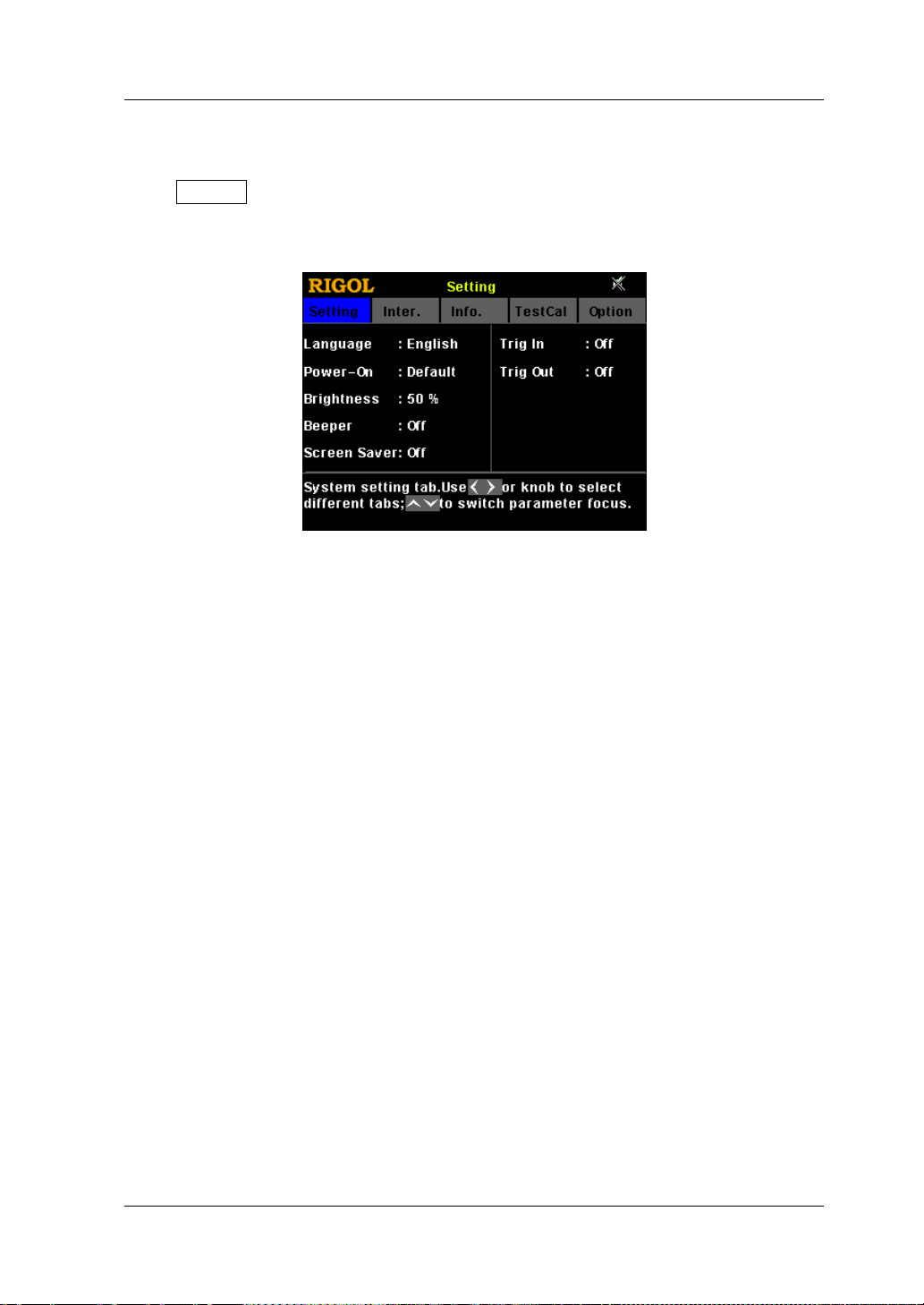
Chapter 2 Front Panel Operations RIGOL
System Setting
Press System to enter the system utility function interface. By default, the "Setting"
tab is selected. You can also press the Left/Right a rrow k ey or use the knob t o select
the system setting tab.
Figure 2-5 System Setting Tab
In the system setting tab, you can select system language, select power-on setting,
set screen brightness, turn on/off the beeper and the screen saver, and turn on/off
trigger input or output.
Select the System Language
DP700 series power supply provides the help information, prompt message, and
interface display in both Chinese and English version.
In the system setting tab, press the Up/Down arrow key to switch the parameter
focus to "Language", and then press the Left/Right arrow key or use the knob to
select the desired language: Chinese or English.
Select Power-on Setting
Select "Default" or "Last" as the power-on setting.
Default: restores defaults w hen the instrument is powered on, refe r to Table 2-3.
Last: restores its last state when the instrument is powered on.
In the system setting tab, press the Up/Down arrow key to switch the parameter
focus to "Power-on", and then press the Left/Right arrow key or use the knob to
select the desired power-on state: Default or Last.
DP700 User’s Guide 2-27
Page 62

RIGOL Chapter 2 Front Panel Operations
Set the Screen Brightness
The settable screen brightness ranges from 1% to 100%.
In the system setting tab, press the Up/Down arrow key to switch the parameter
focus to "Brightness", and then use the num key or knob to select the desired
brightness. For setting method, refer to the descriptions of the help information
displayed at the bottom of the interface or refer to the descriptions in "Parameter
Setting Meth o d ".
Turn On/Off the Beeper
When the beeper is turned on, the
the beeper sounds when you perform the following operations.
When you press the keys on the front panel;
When you rotate the knob;
When an error occurs in remote operation
In the system setting tab, press the Up/Down arrow key to switch the parameter
focus to "Beeper", and then press the Left/Right arro w key or use the knob to turn on
or off the beeper.
icon is displayed in the status bar. In this case,
.
Turn On/Off the Screen Saver
When the screen sa ver function is enabled, if no operation is performe d on the front
panel for more than 25 minutes, the instrument automatically enters the screen
saver mode; if it persists for another 12.5 minutes, the screen of the instrument
stays black.
In the system setting tab, press the Up/Down arrow key to switch the parameter
focus to "Screen Saver", and then press the Left/R ight arrow key or use the knob to
enable or disable the screen saver function.
Enable the Trigger Function
DP700 series power supply p ro vi des t he trigger function (optional ), i ncl udi ng t rigger
input and trigger output. For details of the function, refer to the descriptions in
"Trigger". If you want to use the trigger function, order the option based on the
Order No. available in "Appendix A: Order Information", and then install the
option by referring to "Option Configuration".
2-28 DP700 User’s Guide
Page 63

Chapter 2 Front Panel Operations RIGOL
Tip
Trigger Input:
In the system setting tab, press the Up/Down arrow key to switch the parameter
focus to "Trig In", and then press the Left/ Right a rrow ke y or use the kno b to e nable
or disable the trigger input function.
Trigger Output:
In the system setting tab, press the Up/Down arrow key to switch the parameter
focus to "Trig Out", and then press the Left/Right arrow key or use the knob to
enable or disable the trigger output function.
If the trigger option is n ot installed, you can ena ble neither the trigger input nor
the trigger output function.
DP700 User’s Guide 2-29
Page 64

RIGOL Chapter 2 Front Panel Operations
1
DC Output
Outputs DC: 5 V, 10 mA.
2
TXD (Transmit Data)
Transmits data.
3
RXD (Rece i ve Data)
Receives data.
7*
TRIG-OUT
Outputs the trigger output signal.
8*
TRIG-IN
Receives the trigger input signal.
9
NC
Indicates not connected.
7
3
1
RS232 Interface Setting
You can remotely control the DP700 series power supply via the RS232 interface. Use
the 9-pin RS232 cable (female-to-female, st raight) to connect the RS232 interf ace to
the PC, and set the inte rf ace parameters (such as baud rate, pa rity, etc.) that match
the PC. Then, you can remotely control the instrument.
2
4
5
6
8
9
Figure 2-6 RS232 Interfac e
Table 2-4 Description of Pins of the RS232 Interface
Pin Name Description
4 NC Indicates not connected.
5 SGND Indicates the signal ground.
6 NC Indicates not connected.
Note*: Pin 7 and Pin 8 of the RS232 interface are not used in remote communication. They are
used in the trigger function (optional).
Press System to enter the system utility function i nterface. Press the Left/Right
arrow key or use the k no b t o s e l e ct the "Inter." tab.
2-30 DP700 User’s Guide
Figure 2-7 RS232 Interfac e Tab
Page 65

Chapter 2 Front Panel Operations RIGOL
In the RS232 interface tab, you can set and view the RS232 interface parameters.
1. Baud Rate
The available baud rates include 7200 bps, 9600 bps, 14400 bps, 19200 bps,
38400 bps, 57600 bps, and 11520 0 b ps.
Press the U p/Down a rrow k ey to switch the parameter focus to "Baud Rate", and
then press the Left/Right arrow key or use the knob to select the desired baud
rate.
2. Stop Bit
Stop bit is 1 and cannot be modified.
3. Data Bit
Data bit is 8 and cannot be modified.
4. Parity
The available parity modes include None, Odd, and Even. Press the Up/Down
arrow key to switch the parameter focus to "Parity", and then press the
Left/Right arrow key or use the knob to select the desired parity mode.
DP700 User’s Guide 2-31
Page 66

RIGOL Chapter 2 Front Panel Operations
System Information
Press System to enter the system utility function interface. Press the Left/Right
arrow key or use the k no b t o s e l e ct the "Info." tab.
Figure 2-8 System Information Tab
In the system information tab, you can view the system information of the
instrument, including the device model, serial number, and software version.
2-32 DP700 User’s Guide
Page 67

Chapter 2 Front Panel Operations RIGOL
Test and Calibration
Press System to enter the system utility function i nterface. Press the Left/Right
arrow key or use the knob to select the "TestCal" tab.
Figure 2-9 Test and Calibration Tab
In the test and calibration tab, you can view the test i nformation and aut o calibratio n
information, perform manual calibration, and modify the calibration password.
View Test&Auto Calibration Information
Test information includes the fan state. The fan state is displayed as Low Speed
when the actual output current is less than 2 A; the fan state is displayed as High
Speed when the actual out put current is e qual to or greate r than 2 A. Auto calib ration
information includes the auto calibration status and the last auto calibration time.
Perform the Manual Calibration
DP700 series power supply supports multiple manual calibration items, including
voltage DAC calibration, current DAC cali b r at ion , v oltage ADC calibration, current
ADC calibration, and OVP calibration.
If you want to calibrate the instrument, first enter a calibration password. When
leaving the factory, the instrument has been given a default calibration password
(123456). In the test and calibration tab, press OK to en ter a correct cali bration
password, and then press OK to enter the calibration page. Then, you can calibrate
the instrument. For the detailed calibration methods, please refer to the calibration
guide of this product. After completing the calibrati on, a message will be displayed,
prompting you that calibration is completed.
If needed, y ou can also f ollow the st eps below or ref er t o the help inf ormati on at the
DP700 User’s Guide 2-33
Page 68

RIGOL Chapter 2 Front Panel Operations
CAUTION
bottom of the instrument interface to modify the password. It is a 6-character
password, and can contain nu m bers (0-9) and dots.
Password Modification Procedures:
1. In the calibration page, pre ss the U p/Down ar row k ey or use the knob to switch
the parameter focus to "Passwd".
2. Press OK to enter a new password.
3. Press OK to enter the new password for confirmation.
4. Press OK to complete password modification.
We recommend you to calibrate the instrument every other year. Before leaving
the factory, the instrument has been calibrated by RIGOL.
2-34 DP700 User’s Guide
Page 69

Chapter 2 Front Panel Operations RIGOL
Option Configuration
DP700 series power supply provides the following options:
Trigger: provides the trigger input and output functions.
Timer: outputs based on the preset voltage and current values.
High Resolution: improves the resolution of the instrument.
If you need any of these options, o rder them according to t he Order No. available in
"Appendix A: Order Information", and then install the options according to this
section.
Press System to enter the system utility function i nterface. Press the Left/Right
arrow key or use the k no b t o s e l e ct the "Option" tab.
Figure 2-10 System Option Tab
In the system option tab, you can view the installation status of all options (Official,
Trial, Not Installed) and install the options.
To install an option, you need an option license (each instrument has a unique
license). The option license is a 28-character string, which consists of English letters
and numbers. After you pur chase an option, y ou will obtain a ke y (used for obtaining
the option license). Then, you can install the option according to the f ollowing s teps.
1. Obtain an option license
(1) Log in to the RIGOL official website (
Software License Register to enter the "Registered product license
code" interface.
(2) In the interface, enter the correct key, serial number (press System, and
select the "Info." tab to obtain the serial number of the instrument), and
verification code. Then click Generate to obtain the option license.
Note: The hyphens in the option license should be omitted.
DP700 User’s Guide 2-35
www.rigol.com) , click SERVICE
Page 70

RIGOL Chapter 2 Front Panel Operations
Tip
2. Install the option
Method 1: Front Panel Operations
(1) In the system option tab, press the Up/Down arrow key to switch the
parameter focus to the desired option.
(2) Press OK to enter the License Input interface.
License Input Area Virtual Keypad
Figure 2-11 License Input Interface
(3) In the License Input interface, press the Up/Down/Left/Right arrow key or
use the knob to select the desired character (the English letter is not
case-sensitive) on the virtual keypad, and then press OK to enter the
character. The entered characters will be displayed in the "License Input
Area". While entering the characters, press
to delete the unwanted
character if necessary.
Note: The hyphens in the option license should be omitted.
(4) After inputting a license, s elect "Save" on t he virtual keypad a nd p ress OK.
If the option has been successfully installed, a prompt message will be
displayed; otherwise, a message indicating a failed installation will be
displayed.
If yo u want to quit the installation operation, select "Exit" on the virtual
keypad to give up installing the option, and then press OK.
Method 2: Send SCPI Commands
To set up remote contr ol via the RS 232 interface and send the option installation
command :LIC:SET <license>, refer to "Remote Control".
Wherein, <license> is the option license, a nd the hy phens in the code should be
omitted.
For example, :LIC:SET UVF2L3N3XXKYTB73PPRSA4XDMSRT
2-36 DP700 User’s Guide
Page 71

Chapter 2 Front Panel Operations RIGOL
Remote Locking
DP700 series power supply provides the following two remote locking functions to
avoid any loss caused by misoperation.
Front panel locking: lo cks all keys on the front panel (including the knob, but
excluding On/Off,
Key locking: locks the specified keys or all keys on the front panel (including the
knob, but excluding
Note: You can lock the front panel or keys by only sending SCPI commands .
Front Panel Locking
You can send front panel l ocking command to the DP700 series power supply to lock
the front panel. When the front panel is locked, it indicates that all keys (except
On/Off,
displayed on the status bar.
The syntax and explanation of the commands for locking the front panel are
displaye d below:
Syntax
:SYSTem:LOCK {ON|OFF|1|0} /*Lock or unlock the front panel*/
:SYSTem:LOCK? /*Query whether the front panel is locked*/
Explanation
The parameters {ON|OFF|1|0} indicate locking or unlocking the fr ont panel . When
the parameter val ue is ON|1, it in dicates locking the front panel; when the par ameter
value is OFF|0, it indicates unlocking the front panel .
, and ) on the front panel are locked. and icons will be
, and ).
).
Brief Descriptions of Commands
Braces { } and vertical bar | are not part of the command, and they are not
sent with the commands, but taken as delimiters to better describe the
parameters in the command. The contents enclosed in the braces can
contain multiple paramete r options; and the vertical bar is used to separate
multiple parameter options. When sending the command, you must select
one of the parameters.
The letters in the commands are case-insensitive. The commands can be
input in uppercase letters or in lowercase letters. For abbreviations, you
must enter all the uppercase letters that exist in the command syntax. For
example, :SYSTem:LOCK ON can be abbreviated as :SYST:LOCK ON.
The contents in /*...*/ are explanations for the command.
For details about the SCPI commands, refer to
DP700 User’s Guide 2-37
DP700 Programming Guide
.
Page 72

RIGOL Chapter 2 Front Panel Operations
NUM0|NUM1|NUM2|NUM3|NUM4|NUM5|
/*Num keys*/
KNOB|
/*Knob*/
LEFT|RIGHT|UP|DOWN|
/*Arrow keys*/
OK|
/*Confirmation key*/
The SCPI commands can be sent to the DP700 series power supply by user-defined
programming or PC software. For details, refer to the descriptions in "Remote
Control".
Key Locking
You can send key locking command to the DP700 series power s upply to lock the
keys. You are allowed to lock the specified keys or all keys on the front panel
(including the knob, but excluding
The syntax and explanation of the commands for locking the keys are displayed
below:
Syntax
:SYSTem:KLOCk <key>,{ON|OFF|1|0} /*Lock or un l ock the specified key*/
:SYSTem:KLOCk? <key> /*Query whether the specified key is locked*/
Explanation
The parameter <key> indicates a specified key, and its range is as follows:
SYSTEM|MEMORY|TIMER| /*Function keys*/
OUTPUT| /*Output on/off key*/
). The keys locked cannot be used.
NUM6|NUM7|NUM8|NUM9|DOT|
BACK| /*Return key*/
ALL /*All keys on the front panel
(excluding
knob*/
The parameters {ON|OFF|1|0} indicate locking or unlocking the keys. When the
parameter value is ON|1, it indicates locking the keys; when the parameter
value is OFF|0, it indicates unlocking the keys.
) and the
2-38 DP700 User’s Guide
Page 73

Chapter 2 Front Panel Operations RIGOL
Brief Descriptions of Commands
The angle-bracket < >, brace { }, and vertical bar | are not part of the
command, and they are not sent with the commands, but taken as
delimiters to better describe the parameters in the command. When sending
the command, the parameter enclosed in the angle-bracket must contain an
effective value. The contents enclosed in the braces can contain multiple
parameter options; and the vertical bar is used to separate multiple
parameter options. When sending the comma nd, you must se lect one of the
parameters.
The letters in the commands are case-insensitive. The commands can be
input in uppercase letters or in lowercase letters. For abbreviations, you
must enter all the uppercase letters that exist in the command syntax. For
example, :SYSTem:KLOCk? MEMORY can be abbreviated as :SYST:KLOC?
MEMORY.
The contents in /*...*/ are explanations for the command.
For details about the SCPI commands, refer to
DP700 Programming Guide
.
The SCPI commands can be sent to the DP700 series power supply by user-defined
programming or PC software. For details, refer to the descriptions in "Remote
Control".
DP700 User’s Guide 2-39
Page 74

Page 75
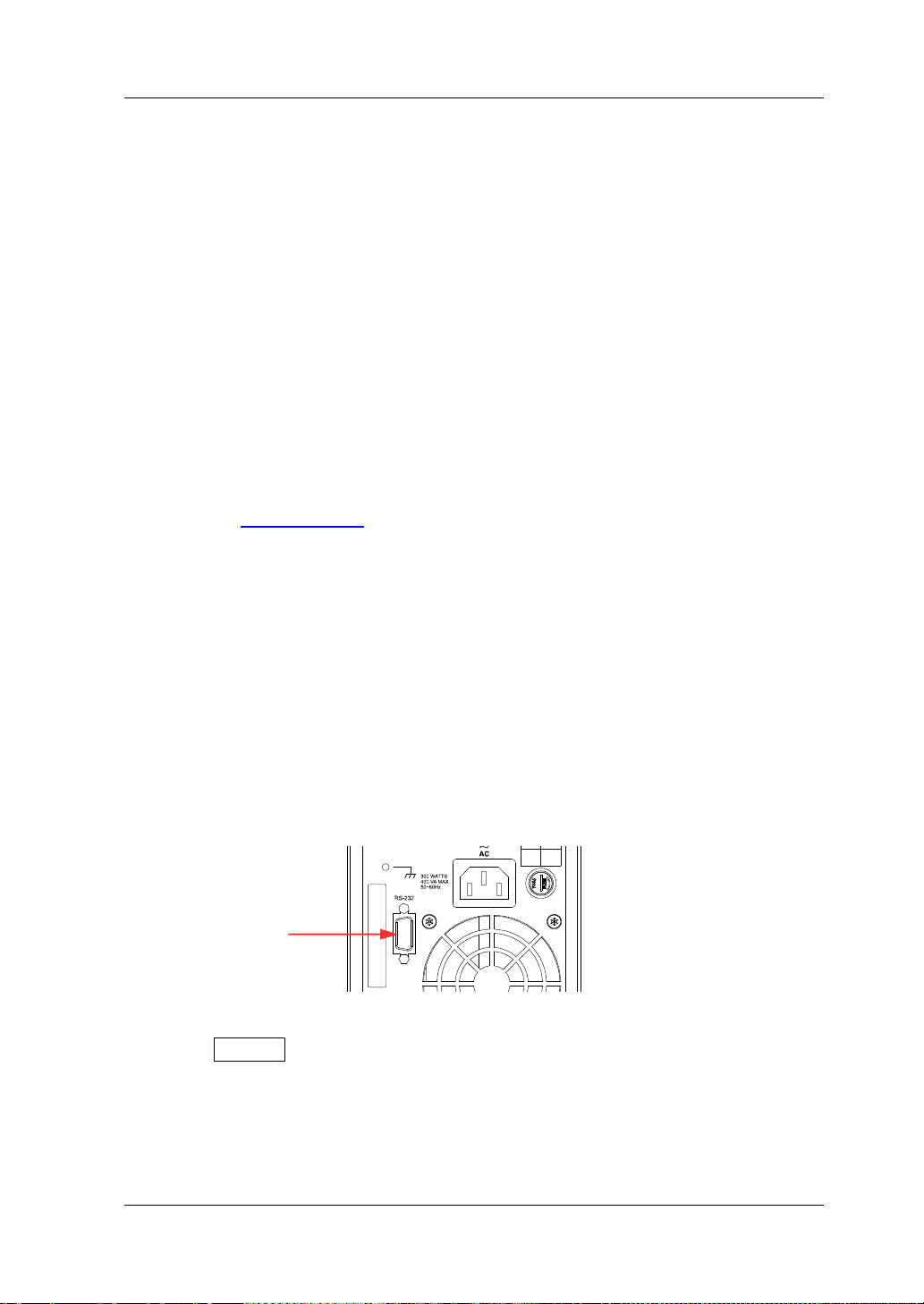
Chapter 3 Remote Control RIGOL
120V 250Vac
220V T2.5A
240V 250Vac
RS232 Interface
Chapter 3 Remote Control
You can remotely control the DP700 series power supply in the two following ways.
User-defined programming
Users can program and control the instrument by using the SCPI (Standard
Commands for Programm a ble Instr uments) commands. For details about the
SCPI commands and programming, refer t o
DP700 Programming Guide
Operation Procedures:
(1) Set up communication between the instrument and PC.
(2) Send commands by programming in LabVIEW, MATLAB, etc.
Use the PC software
Users can use the PC software to send commands to control the instrument
remotely. RIGOL Ultra Si gma is reco mmended. Y ou can log in to RIGOL official
website (
www.rigol.com) to download the software.
Operation Procedures:
(1) Set up communication between the instrument and PC.
(2) Run Ultra Sigma and search for the instrument resource.
(3) Open the remote command control panel to send commands.
DP700 series power supply can communicate with the PC via the RS232 interface.
This chapter will illustrate how to use the Ultra Sigma software to remotely control
the power supply via the RS232 interface.
1. Connect the power supply to the PC
Use the 9-pin RS232 cable (female-to-female, straight) to connect the power
supply to the PC through the RS232 interface on the rear panel.
.
2. Set the parameters for the RS232 interface
Press System, and then select the "Inter." tab. Set the parameters (baud rate
and parity) for the RS232 i nterface based on the set t ing descriptions in "RS232
Interface Setting".
3. Add the device resource
DP700 User’s Guide 3-1
Start Ultra Sigma, and then click "RS232". A window is displayed as shown in
Page 76

RIGOL Chapter 3 Remote Control
Figure (a).
(a)
As shown in Figure (a), in the "R S232 Setting " tab, set Baud Rate, Parity, Data
Bits, and Stop Bit that match the current parameters of the RS232 interface of
the instrument (Note: You must select "None" under the "Fl ow C ont rol " option,
and select "\n" under the "End Mark" option). After completing the set tings, click
"Test". If the test succeeds, a dialog box, as shown in Figure (b), is displayed.
(b)
Note: If the test fails, check whether the instrument can com municate with th e
PC via the RS232 cable normally, and whether the current RS232 settings in
Ultra Sig ma match those of the instrument.
In the dialog box shown in Figure (b), click "OK". Then the "Add" button in the
"RS232 Setting" tab in Figure (a) will be enabled. Click "Add", and then the
currently selected instrument resource will be displayed on the right section of
the window, as shown in Figure (c). Then, click "OK" to add the instrument
resource.
(c)
3-2 DP700 User’s Guide
Page 77
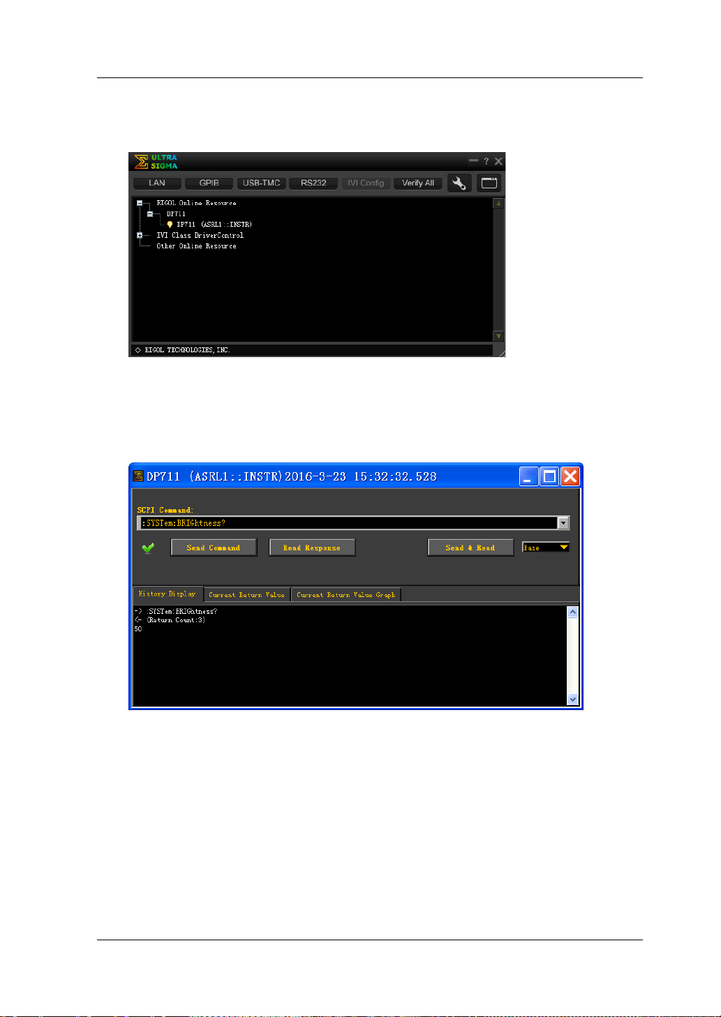
Chapter 3 Remote Control RIGOL
The added RS232 instrument resource will be displayed under the "RIGOL
Online Resource" directory, as shown in the figure below.
4. Control the instrument remotely
Right-click the resource name "DP711 (ASRL1::INSTR)", and select "SCPI Panel
Control" to open the remote command control panel. Then you can send
commands and read data t h rough the panel.
DP700 User’s Guide 3-3
Page 78

Page 79
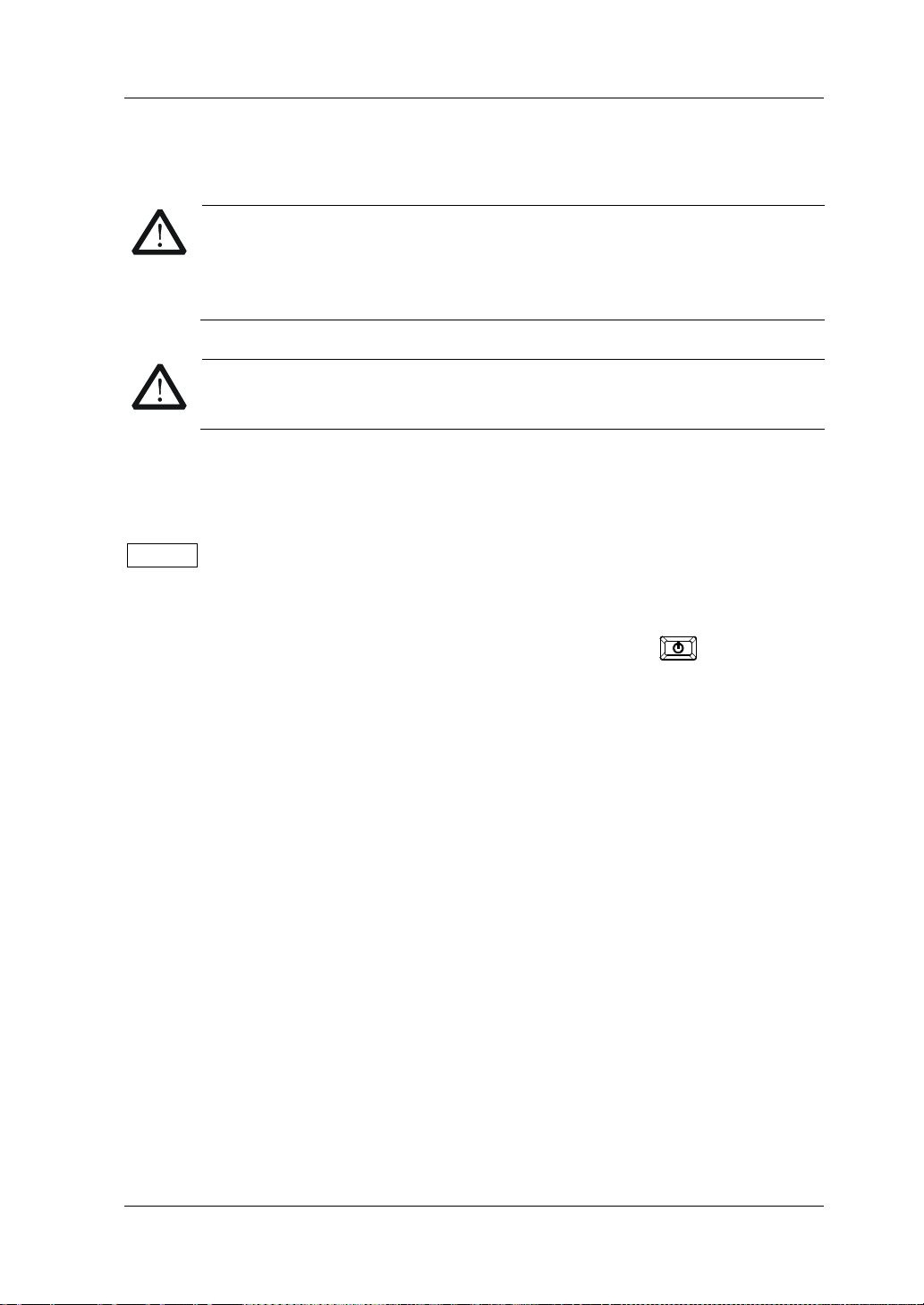
Chapter 4 Troubleshooting RIGOL
WARNING
WARNING
RIGOL.
Chapter 4 Troubleshooting
Do not disassemble the instrument by yourself. Otherwise, you might be
exposed to the danger of electric shock. Only RIGOL authorized
personnel are allowed to repair, make adjustments, or replace the
components of the instrument.
Only the exclusive power cord designed for the instrument can be used .
For replacement of the power cord, please contact
This chapter lists the potential problems or failure, as well as the solutions in using
the instrument. If the following problems occur, locate and resolve the problems
according to the following steps. If the problems still persist, contact RIGOL and
provide your instrument information to us. (For instrument information, press
System, and then select the "Info." tab.)
1. The i nstrument cannot be powered on.
(1) Check whether the power cord is damaged or correctly connected.
(2) Check whether you have pressed down the Power key
(3) Plug out the power cor d, and check whet her the AC s elector is in the proper
position, whether the fuse conforms to the fuse rating, and whether the
fuse is intact. For fuse replacement, refer to "Fuse Replacement".
(4) If the problem still persists, contact RIGOL.
2. The constant volta ge output is abnormal.
(1) Check whether the max output power meets the load requirement.
(2) Check whether there is a short across the cable that connects the l oad and
the power supply, and check whether the connection is in good condition.
(3) Check whether there is a problem with the load.
(4) Check whether the current setting value is proper. If the value is too low,
increase the value appropriately.
(5) If the problem still persists, contact RIGOL.
3. The constant current output is abnormal.
(1) Check whether the max output power meets the load requirement.
(2) Check whether there is a broken circuit across the cable that connects the
load and the power supply, and check whether the connection is in good
condition.
(3) Check whether there is a problem with the load.
(4) Check whether the voltage setting value is proper. If the value is too low,
increase the value appropriately.
.
DP700 User’s Guide 4-1
Page 80

RIGOL Chapter 4 Troubleshooting
(5) If the problem still persists, contact RIGOL.
4. The screen display is too dark.
(1) Press System to enter the system utility function interface. Press the
Left/Right arrow key or use the knob to select the "Setting" tab.
(2) In the system setting tab, press the Up/Down arrow key to switch the
parameter focus to "Brightness", and then use the num key or knob to
adjust the brightness to a proper state.
5. How do I switch the system language?
(1) Press System to enter the system utility function interface. Press the
Left/Right arrow key or use the knob to select the "Setting" tab.
(2) In the system setting tab, press the Up/Down arrow key to switch the
parameter focus to "Language", and then press the Left/Right arrow key or
use the knob to select the desired language.
6. The RS232 interface cannot work normally.
(1) Check whether the RS232 cable is straight-though and whether it is intact.
(2) Check whether the current RS232 settings of the software match those of
the instrument.
(3) If the problem still persists, contact RIGOL.
4-2 DP700 User’s Guide
Page 81

Chapter 5 Specifications RIGOL
DC Output (0°C to 40°C)
Standard: 10 mA
Standard: 10 mV
High resolution option installed: 1 mV
Standard: 10 mA
Chapter 5 Specifications
All the technical specifications are guaranteed when the instrument has been
working for more than 30 minutes under the specified operating temperature.
Model Voltage/Current Rating OVP/OCP
DP711 0 V to 30 V/0 A to 5 A 0.01 V to 33 V/0.01 A to 5.5 A
DP712 0 V to 50 V/0 A to 3 A 0.01 V to 55 V/0.01 A to 3.3 A
Load Regulation, ±(% of Output + Offset)
Voltage <0.01% + 2 mV
Current <0.01% + 2 mA
Line Regulation, ±(% of Output + Offset)
Voltage <0.01% + 2 mV
Current <0.01% + 2 mA
Ripple and Noise (20 Hz to 20 MHz)
Model Normal Mode V ol t a ge Normal Mode Current
DP711 <500 μVrms/3 mVpp
DP712 <500 μVrms/4 mVpp
Annual Accuracy
Programming
Readback
[1]
(25°C ± 5°C), ±(% of Output + Offset)
Voltage 0.05% + 20 mV
Current 0.2% + 10 mA
Voltage 0.05% + 20 mV
Current 0.2% + 20 mA
Resolution
Voltage
Programming
Current
Voltage
Readback
Current
Voltage
Display
Current
Standard: 10 mV
High resolution option installed: 1 mV
High resolution option installed: 1 mA
Standard: 10 mA
High resolution option installed: 1 mA
Standard: 10 mV
High resolution option installed: 1 mV
High resolution option installed: 1 mA
<2 mArms
DP700 User’s Guide 5-1
Page 82

RIGOL Chapter 5 Specifications
Transient Response Time
Less than 50 μs for output voltage to recover to within 15 mV following a change in output
current from full load to half load or from ha l f loa d to full load.
Command Processing Time
<100 ms
[2]
OVP/OCP
Accuracy,
±(% of Output + Offset)
OVP Activation Time <10 ms (OVP>1 V)
0.5% + 0.5 V/0.5% + 0.5 A
Voltage Programming Sp e ed
Up
Down
Full Load 150 ms
No Load 100 ms
Full Load 30 ms
No Load 450 ms
[3]
(within 1% of the total variation range)
Temperature Coefficient
Voltage 0.01% + 2 mV
Current 0.02% + 3 mA
[4]
, ±(% of Output + Offset)
Stability
Voltage 0.02% + 2 mV
Current 0.1% + 3 mA
[5]
, ±(% of Output + Offset)
Mechanical
Dimensions 140 mm (W) x 202mm (H) x 332 mm (D)
Weight Net: 6.9 kg
Power
AC Input Power
(50 Hz to 60 Hz)
Maximum Input Power 400 VA
100 Vac ± 10%, 120 V a c ± 10%, 220 Vac ± 10%,
and 240 Vac ± 10% (max: 253 Vac)
Interface
RS232 1 (Male)
Environment
Cooling Method Fan Cooled
Operating Temperature 0°C to 40°C for full rated output
5-2 DP700 User’s Guide
Page 83

Chapter 5 Specifications RIGOL
Maximum Output Floating
Voltage to Ground
±240 Vdc
Storage Temperature -40°C to 70°C
Humidity 5% to 80% RH
Altitude Below 2,000 m
[1]
Note
warm-up.
Note
and SOURce commands.
Note
Note
Note
: The accuracy parameters are acquired through calibration under 25°C after 1-hour
[2]
: The maximum time required for the output to begin to change after receiving the APPLy
[3]
: Exclude the command processing time.
[4]
: Maximum change in output/readback per °C after a 30-minute warm-up.
[5]
: Following a 30-minute warm-up, change in output over 8 hours under constant load,
line, and ambient temperature.
DP700 User’s Guide 5-3
Page 84

Page 85

Chapter 6 Appendix RIGOL
Description
Order No.
Quick Guide (hard copy)
-
Timer
TIMER-DP700
Chapter 6 Appendix
Appendix A: Order Information
Model
Standard
Accessories
Optional
Accessories
Programmable Linear DC Power Supply (single channel,
30 V/5 A)
Programmable Linear DC Power Supply (single channel,
50 V/3 A)
Power Cord Either one of the following specified fuses:
Fuse 50T-050H 250V 5A (AC Selector: 100 Vac or
120 Vac)
Fuse 50T-025H 250V 2.5A (AC Selector: 220 Vac or
240 Vac)
High Resolution HIRES-DP700
Trigger (external synchronous trigger input and output) TRIGGER-DP700
9-Pin RS232 Cable (female-to-female, straight) CB-DB9-DB9-F-F-150
DP700 Series Rack Mount Kit (for a single instrument) RM-1-DP700
DP700 Series Rack Mount Kit (for two instruments) RM-2-DP700
DP700 Series Rack Mount Kit (for three instruments) RM-3-DP700
DP711
DP712
-
Note: For all the accessories and options, pleas e contact t h e local office of RIGOL.
DP700 User’s Guide 6-1
Page 86

RIGOL Chapter 6 Appendix
Appendix B: Warranty
RIGOL TECHNOLOGIES, INC. (hereinafter referred to as RIGOL) warrants that the
product will be free from defects in materials an d workmanshi p within the warranty
period. If a product proves defective within the warranty period, RIGOL guarantees
free replacement or repair for th e defective product.
To get repair service, please contact with your nearest RIGOL sales or service office.
There is no other warranty, expressed or implied, except such as is expressly set
forth herein or other applicable warranty card. There is no implied warranty of
merchantability or fitness for a particular purpose. Under no circumstances shall
RIGOL be liable for a ny conseque ntial, indirect, ensuing, or specia l damage s for any
breach of warranty in any case.
6-2 DP700 User’s Guide
Page 87

Index RIGOL
Index
AC selector ............................... 1-11
air outlet .................................. 1-10
appearance and dimensions ......... 1-3
beeper ..................................... 2-28
built-in help .............................. 1-17
CC ............................................. 2-5
constant current output ............... 2-5
constant voltage output ............... 2-2
CV ............................................. 2-2
default settings ......................... 2-24
end state ................................. 2-12
file deletion .............................. 2-22
file recalling ............................. 2-22
file storage ............................... 2-21
front panel ................................. 1-4
front panel locking .................... 2-37
function keys .............................. 1-4
fuse ......................................... 1-17
general inspection ....................... 1-2
key locking ............................... 2-38
LCD ........................................... 1-4
license ..................................... 2-35
manual calibration .................... 2-33
number of cycles ...................... 2-11
number of output groups ........... 2-11
option ...................................... 2-35
option license ........................... 2-35
order informatio n ........................ 6-1
output check ............................ 1-15
output terminals ......................... 1-6
parallel connected power supply .. 2-9
parameter setting method .......... 1-18
power-on inspection .................. 1-14
power-on setting ....................... 2-27
rear panel ................................. 1-10
remote contr ol ........................... 3-1
remote locking .......................... 2-37
RS232 Interface ........................ 2-30
screen saver ............................. 2-28
series connected power supply .... 2-8
specifications ............................. 5-1
store and recal l ......................... 2-20
switch lever .............................. 1-11
synchronous output ................... 2-17
system information .................... 2-32
system language ....................... 2-27
system setting .......................... 2-27
system utility function ................ 2-26
test and calibration .................... 2-33
timer ........................................ 2-10
timer parameters ....................... 2-11
timing output ............................ 2-14
trigger ............................. 2-16, 2-28
trigger input ............................. 2-16
trigger mode ............................. 2-11
trigger output ........................... 2-17
troubleshooting .......................... 4-1
UR ............................................ 2-2
user interface ............................ 1-12
user-defined programming .......... 3-1
DP700 User’s Guide 1
 Loading...