

Page 1

RIGOL
User’s Guide
DG5000 Series
Function/Arbitrary Waveform Generator
Feb. 2014
RIGOL Technologies, Inc.
Page 2

Page 3

RIGOL
Guaranty and Declaration
Copyright
© 2010 RIGOL Technologies, Inc. All Rights Rese rved.
Trademark Information
RIGOL is a registered trademark of RIGOL Technologies, Inc.
Publication Number
UGB07109-1110
Notices
RIGOL products are protected by patent law in and outside of P.R.C.
RIGOL reserves the right to modify or change parts of or all the specifications
and pricing policies at company’s sole decision.
Information in this publication replaces all previously corresponding material.
RIGOL shall not be liable for losses caused by either incidental or cons equential
in connection with the fu r nis hing , use or perfo rman ce of this manual as well as
any information contained.
Any part of this document is forbidden to copy or photocopy or rearrange without
prior written approval of RIGOL.
Product Certification
RIGOL guarantees this product conforms to the national and industrial standards in
China as well as the ISO 9 001:200 8 st anda r d and th e ISO 1400 1:200 4 stan da rd. Other
international standard conformance certification is in progress.
Contact Us
If you have any problem or requirement when using our products or this manua l,
please contact RIGOL.
E-mail: service@rigol.com
Websites: www.rigol.com
User’s Guide for DG5000
I
Page 4

RIGOL
Safety Requirement
General Safety Summary
Please review the f ollowin g safety precautions carefully before putting the instrument
into operation so as to avoid any personal injuries or damages to the instrument and
any product connected to it. To prevent potential hazards, please use the instrument
only specified by this manual.
Use Proper Power Cord.
Only the power cord designed for the instrument and authorized for use within the
local country could be used.
Ground The Instrument.
The instrument is grounded through the Protective Earth lead of the power cord. To
avoid electric shock, it is essential to connect the earth terminal of power cord to the
Protective Earth terminal before any inputs or outputs.
Connect the Probe Correctly.
If a probe is used, do not connect the ground lead to high volt age since it has the
isobaric electric potential as ground.
Observe All Terminal Ratings.
To avoid fire or shock hazard, observe all ratings and markers on the instrument and
check your manual for more information about ratings before connecting.
Use Proper Overvoltage Protection.
Make sure that no o vervolt age (such as that caused by a thunde rstorm) can reach the
product, or else the operator might expose to danger of electrical shock.
Do Not Operate Without Covers.
Do not operate the instrument with covers or panels removed.
Do Not Insert Anything into the Holes of Fan.
Do not insert anything into the holes of the fan to avoid damaging the instrument.
II
User’s Guide for DG5000
Page 5

RIGOL
Use Proper Fuse.
Please use the specified fuses.
Avoid Circuit or Wire Exposure.
Do not touch exposed junctions and components when the unit is powered.
Do Not Operate With Suspected Failures.
If you suspect damage occurs to the instrument, have it i nspected by qualified service
personnel before further operations. Any maintenan ce, adjustment or replacement
especially to circuits or accessories must be performed by RIGOL authorized
personnel.
Keep Well Ventilation.
Inadequate ventilation ma y cause increasing of temperat ure or da mages to t he device.
So please keep well ventilated and inspect the intake and fan regularly.
Do Not Operate in Wet Conditions.
In order to avoid short circuiting to the interior of the device or elect ric shock, please
do not operate in a humid environment.
Do Not Operate in an Explosive Atmosphere.
In order to a void damages to the device or personal i njuries, it is imp ortant to operat e
the device away fr om an exp losive a tmosphere.
Keep Product Surfaces Clean and Dry.
To avoid the infl uence of dust and /or moisture in air, please keep the su rface of device
clean and dry.
Electrostatic Prevention.
Operate in an electrostatic discharge protective area environment to avoid damages
induced by static dischar ges. Alwa ys ground both th e internal an d external con ductors
of the cable to release static before connecting.
Proper Use of Battery.
If a battery is supplied, it must not be e xpose d to high temperature or in cont act with
fire. Keep it out of the reach of children. Improper change of battery (note: lithium
battery) may cause explosion. Use RIGOL specified battery only.
User’s Guide for DG5000
III
Page 6

RIGOL
Handling Safety.
Please handle with care during transportation to avoid damages to buttons, knob
interfaces and other parts on the panels.
IV
User’s Guide for DG5000
Page 7

RIGOL
indicates potential damage to the instrument or other property might
Hazardous
Safety
Protective
Chassis
Test
Safety Terms and Symbols
Terms Used in this Manual. These terms may appear in this manual:
WARNING
Warning statements indicate the conditions or practices that could result
in injury or loss of life.
CAUTION
Caution statements indicate the conditions or practices that could result
in damage to this product or other property.
Terms Used on the Product. These terms may appear on the Product:
DANGER indicates an injury or hazard may immediately happen.
WARNING indicates an injury or hazard may be accessi ble pote nt iall y.
CAUTION
occur.
Symbols Used on the Product. These symbols may appear on the product:
Voltage
Warning
Earth
Terminal
Ground
User’s Guide for DG5000
Ground
V
Page 8

RIGOL
Allgemeine Sicherheits Informationen
Überprüfen Sie diefolgenden Sicherheitshinweise
sorgfältigumPersonenschädenoderSchäden am Gerätundan damit verbundenen
weiteren Gerätenzu vermeiden. Zur Vermeidung vonGefahren, nu t zen Sie bitte das
Gerät nur so, wiein diesem Handbuchangegeben.
Um Feuer oder Verletzungen zu vermeiden, verwenden Sie ein
ordnungsgemäßes Netzkabel.
Verwenden Sie für dieses Gerät nur das für ihr Land zugelass ene u nd genehm igte
Netzkabel.
Erden des Gerätes.
Das Gerät ist durch den Schutzleiter im Netzkabel geerdet. Um Gefahren durch
elektrischen Schlag zu vermeiden, ist es unerlässlich, die Erdung durchzuführen. Erst
dann dürfen weitere Ein- oder Aus gä nge verbunde n werden.
Anschluss einesTastkopfes.
Die Erdungsklemmen der Sonden sindauf dem gleichen Spannungspegel des
Instruments geerdet. Schließe nSie die Erdungsklemmen an keine hohe Spannung an.
Beachten Sie alle Anschlüsse.
Zur Vermeidung von Feuer oder Stromschlag, beachten Sie alle Bemerkungen und
Markierungen auf dem Instrument. Befolgen Sie die Bedienungsanleitung für weitere
Informationen, bevor Sie weitere Anschlüsse an das Instrument legen.
Verwenden Sie einen geeigneten Überspannungsschutz.
Stellen Sie sicher, daß keinerlei Überspannung (wie z.B. durch Gewitter verursacht)
das Gerät erreichen kann. Andernfallsbestehtfür den Anwender die
GefahreinesStromschlages.
Nicht ohne Abdeckung einschalten.
Betreiben Sie das Gerät nicht mit entfernten Gehäuse-Abdeckungen.
Betreiben Sie das Gerät nicht geöffnet.
Der Betrieb mit offenen oder entfernten Gehäuseteilen ist nicht zulässig. Nichts in
entsprechende Öffnungen stecken (Lüfter z.B.)
Passende Sicherung verwenden.
Setzen Sie nur die spezifikationsgemäßen Sicherungen ein.
Vermeiden Sie ungeschützte Verbindungen.
Berühren Sie keine unisolierten V erbindungen ode r Baugruppen, während das Gerät in
Betrieb ist.
VI
User’s Guide for DG5000
Page 9

RIGOL
Betreiben Sie das Gerät n ic h t i m Fehlerfall.
Wenn Sie am Gerät einen Defekt vermuten, sorgen Sie dafür, bevor Sie das Gerät
wieder betreiben, dass eine Untersuchung durch qualifiziertes Kundendienstpersonal
durchgeführt wird.Jedwede Wartung, Einstellarbeiten oder Austausch von Teilen am
Gerät, sowie am Zubehör dürfen nur von RIGOL autorisie rtem P ersona l durch geführt
werden.
Belüftung sicherstellen.
Unzureichende Belüftung kann zu Temperaturanstiegen und somit zu thermischen
Schäden am Gerät führen. Stelle n Sie deswegen die Belüftung sicher und kontrollieren
regelmäßig Lüfter und Belüftungsöffnungen.
Nicht in feuchter Umgebung betreiben.
Zur Vermeidun g v on Kurzschluß im Geräteinneren u nd Stro mschla g betreiben Sie das
Gerät bitte niemals in feuchter Umgebung.
Nicht in explosiver Atmosphäre betreiben.
Zur Ve rm e idung von P e rsonen- und Sachschäden ist es unumgänglich, das Gerät
ausschließlich fernab jedweder explosiven Atmosphäre zu betreiben.
Geräteoberflächen sauber und trocken halten.
Um den Einfluß von Staub und Feuchtigkeit aus der Luft auszuschließen, halten Sie
bitte die Geräteoberflächen sauber und trocken.
Schutz gegen elektrostatische Entladung (ESD).
Sorgen Sie für eine elektrostatisch geschützte Umgebung, um somit Schäden und
Funktionsstörungen durch ESD zu vermeiden. Erden Sie vor dem Anschluß immer
Innen- und Außenleiter der Verbindungsleitung, um statische Aufladung zu entladen.
Die richtige Verwendung desAkku.
Wenneine Batterieverwendet wird, vermeiden Sie hohe Temperaturen bzw. Feuer
ausgesetzt werden.Bewahren Sie es außerhalbder Reichweitevon Kindern
auf . UnsachgemäßeÄnderung derBatterie(Anmerkun g:Lithiu m-Batterie)kann zu einer
Explosion führen. VerwendenSie nur von RIGOLangegebenenAkkus.
Sicherer Transport.
Transportieren Sie das Gerät sorgfältig (Verpackung!), um Schäden an
Bedienelementen, Anschlüssen und anderen Teilen zu vermeiden.
User’s Guide for DG5000
VII
Page 10

RIGOL
WARNING
CAUTION
DANGER
WARNING
weist auf eine Verletzung oder Gefäh rdung hin, die möglicherweise
CAUTION
bedeutet, dass eine mögliche Beschädigung des Instruments oder
Sicherheits Begriffe und Symbole
Begriffe in diesem Guide. Diese Begriffe können in diesem Handbuch
auftauchen:
Die Kennzeichnung WARNING beschreibt Gefahrenq uelle n die leibliche
Schäden oder den Tod von Personen zur Folge haben können.
Die Kennzeichnung Caution (Vorsicht) beschreibt Gefahrenquellen die
Schäden am Gerät hervorrufen können.
Begriffe auf dem Produkt. Diese Bedingungen können auf dem Produkt
erscheinen:
weist auf eine Verletzung ode r Gefäh r dun g hin, die sof ort
geschehen kann.
nicht sofort geschehen.
anderer Gegenstände auftreten kann.
Symbole auf dem Produkt. Diese Symbole können auf dem Produkt
erscheinen:
GefährlicheS
pannung
SicherheitsHinweis
Schutz-erde Gehäusemasse Erde
VIII
User’s Guide for DG5000
Page 11

RIGOL
To avoid damages to the instrument, do not expose them to liquids which
General Care and Cleaning
General Care
Do not leave or store the instrument exposed to direct sunlight for long periods of
time.
Cleaning
Clean the instrument regularly according to its operating conditions. To clean the
exterior surface, perform the following steps:
1. Disconnect the instrument from all power sources.
2. Clean the loose dust on t he outside of the instrument with a lint- free cloth (with
a mild detergen t or water). When clean the LCD, take care to avoid sc a rifying it .
CAUTION
have causticity.
WARNING
To avoid injury resulting from short circuit, make sure the instrument is
completely dry before reconnecting into a power sour ce.
User’s Guide for DG5000
IX
Page 12

RIGOL
Environmental Consideratio ns
The following symbol indicates that this product complies with the requirements in
WEEE Directive 2002/96/EC.
Product End-of-Life Handling
The equipment may contain substances that could be harmful to the environment or
human health. In order to avoid release of su ch subs tances into the e nvir onme nt and
harmful to human health, we encourage you to recycle this product in an appropriate
system that will ensu re that most of the materi als are reused or recycled appropriately.
Please contact your local authorities for disposal or recycling information.
X
User’s Guide for DG5000
Page 13

RIGOL
DG5000 Series Overview
DG5000 is a multifunctional generat or that combines many functions in one, including
Function Gene rat or, Arbitrary W ave form Gener ator, IQ Base band S ource/IQ IF Source,
Frequency Hopping Source (optional) and Pattern G enerator (optional). It provides
single and dual-channel models. The dual-channel model, with two channels having
complete equivalent functions and precisely adjustable phase deviation between the
two channels, is a real dual-channel signal generator.
DG5000, adopting the Direct Digital Synthesize r (DDS) technology , can provide stable,
precise, pure and lo w distortion signal. The user-friendly interface design and panel
layout bring users exceptional experience. Besides, the remote control of the
generator can be easily done through different standard configuration interfaces,
which provides more solutions for users.
Main Features:
4.3 inches, 16M true color TFT LCD.
350 MHz, 250 MHz, 100 M Hz or 70 MHz maximum sine output fre quency, 1 GSa/s
sample rate, 14 bits resolution.
Single/dual-channel models. The dual-channel model supports frequency and
phase coupling.
The 16+2 channels digital output module (optional) together with the analog
channel can rebuild the more mixed signals in daily practice.
Support an external power amplifier (optional) that can be configured online.
Support fre quency hoppin g output (optional) with hopping interval up to 80ns
and arbitrary editing of frequency hopping patterns.
14 standard waveform functions:
Sine, Square, Ramp, Pulse, Noise, Sinc, Exponential Rise, Exponential Fall, ECG,
Gauss, Haversine, Lorentz, Dual Tones and DC.
Rise/Fall Time of the Pulse could be adjusted separately.
Enable to edit ar bit ra ry w a v ef orm up to 512 kpts and output arbitrary waveforms
up to 128 Mpts.
Support AM, FM, PM, ASK, FSK, PSK an d PWM modulati on s .
Support user-defined IQ vector signal modulation and IQ base ba nd/IF source
output.
Support F requency Sw e ep a nd Burst ou t put.
Abundant I/O: waveform output, synchronous signal output, modulation input,
User’s Guide for DG5000
XI
Page 14

RIGOL
10 MHz clock input/output, trigger input/output.
Enable to store and recall waveform data and instrument state, and support
versatile file types. Standard configuration with 1 GBytes flash memory.
Plenty of standard interfaces: double USB Hosts, USB Device, LAN, and GPIB
(IEEE-488.2).
Seamlessly interconnected with RIGOL USB-TMC digital oscilloscopes for loading
and reappearing waveforms.
Support USB flash device storage for FAT files.
Support PictBridge printer.
Provide security lock hole.
Support remote control through 10/100M Ethernet web.
Conform to LXI-C instrument standards (Version 1.2).
Provide Chinese and English built-in help and input methods.
Provide powerful waveform editing PC software.
XII
User’s Guide for DG5000
Page 15

RIGOL
Document Overview
Chapter 1 Quick Start
This chapter introduces the front/rear panel, user interface and main functions, as
well as announcements during first use of the instrument.
Chapter 2 Basic Waveform Output
This chapter introduces how to output basic waveforms, e.g. Sine, Square etc.
Chapter 3 Arbitrary Waveform Output
This chapter introduces how to output built-in or us er-defined waveforms.
Chapter 4 Common Modulation Output
This chapter introduces how to output common modulated waveforms, e.g. AM, FSK,
PWM etc.
Chapter 5 IQ Modulation Output
This chapter introduces how to implement IQ modulated waveform output.
Chapter 6 Frequency Sweep Output
This chapter introduces how to generate a frequency Sweep.
Chapter 7 Burst Output
This chapter introduces how to generate a Burst waveform.
Chapter 8 FH Output
This chapter introduces how to implement frequency hopping output.
Chapter 9 Store and Recall
This chapter introduces ho w to store and recall the w avef orm data and t he instrument
state settings.
Chapter 10 Advanced Operations
This chapter introduces the advanced ope rations of the instrument, including system
parameters setting, waveform saving and printing, functions expansion and the
remote control interfaces configuration.
Chapter 11 Remote Control
This chapter introduces how to control the instrument through remote mode.
Chapter 12 Troubleshooting
This chapter lists commonly encountered failures that may appear during the use of
the generator and their solutions.
User’s Guide for DG5000
XIII
Page 16

RIGOL
Chapter 13 Specifications
This chapter lists the performances and general specif ic ations of the instrument.
Chapter 14 Appendix
This chapter provides the information about the options and accessories, as well as
other points for attention.
Format Conventions in this Manual
1. Buttons:
The function k ey at the front panel is denoted by the format of “Text Box + Button
Name (Bold)” in the manual, for example, Sine.
2. Menu Softkey:
The menu softkey is denoted by the format of “Character Shading + Menu Wo r d
(Bold)” in the manual, f or e xample, Freq.
3. Operation Steps:
The next step of the operation is denoted by an arrow “” in the manual. For
example, Sine Freq represents pressing the function key Sine at the front
panel and then pressing the menu softkey Freq.
Content Conventions in this Manual
Illustrations in thi s manual are based on t he dual-channel model, but all the functions
and performance of the single-channel model has been contained.
DG5000 series cover the following models:
Model Channels Max. Frequency Sample Rate
DG5352 2 350 MHz 1 GSa/s
DG5351 1 350 MHz 1 GSa/s
DG5252 2 250 MHz 1 GSa/s
DG5251 1 250 MHz 1 GSa/s
DG5102 2 100 MHz 1 GSa/s
DG5101 1 100 MHz 1 GSa/s
DG5072 2 70MHz 1 GSa/s
DG5071 1 70MHz 1 GSa/s
XIV
User’s Guide for DG5000
Page 17

RIGOL
Contents
Guaranty and Declaration .......................................................................... I
Safety Requirement .................................................................................. II
General Safety Summary ............................................................................ II
Safety Terms and Symbols .......................................................................... V
Allgemeine Sicherheits Informationen .......................................................... VI
Sicherheits Begriffe und Symbole ............................................................. VIII
General Care and Cleaning ......................................................................... IX
Environmental Considerations ...................................................................... X
DG5000 Series Overview.......................................................................... XI
Document Overview .............................................................................. XIII
Chapter 1 Quick Start ............................................................................. 1-1
General Inspection .................................................................................. 1-2
Handle Adjustment .................................................................................. 1-3
Appearance and Dim ensions ..................................................................... 1-4
Front Panel ............................................................................................. 1-5
Rear Panel ............................................................................................ 1-11
Power on the Ge n erator ......................................................................... 1-14
User Interface ....................................................................................... 1-15
Parameter Mode ............................................................................. 1-15
Graph Mode ................................................................................... 1-15
To Rack Mount the Instrument ................................................................ 1-17
Kit Parts List ................................................................................... 1-17
Installation Tool .............................................................................. 1-18
Space Requirements for Installation .................................................. 1-18
Installation Procedures .................................................................... 1-19
To Use the Security Lock ........................................................................ 1-22
To Use the Built-In Help ......................................................................... 1-23
Chapter 2 Basic Waveform Output ......................................................... 2-1
To Output Sine Waveform ........................................................................ 2-2
To Output Square Waveform ..................................................................... 2-5
To Output Ramp Waveform ...................................................................... 2-6
To Output Pulse Waveform ....................................................................... 2-7
To Output Noise Waveform ..................................................................... 2-10
User’s Guide for DG5000
XV
Page 18

RIGOL
Align Phase ........................................................................................... 2-11
Chapter 3 Arbitrary Waveform Output ................................................... 3-1
To Enable Arbitrary Waveform .................................................................. 3-2
Output Mode .......................................................................................... 3-4
Normal Mode ................................................................................... 3-4
Play Mode ........................................................................................ 3-5
To Select Arbitrary Waveform ................................................................... 3-6
Built-In Waveform ............................................................................. 3-6
Stored Waveform ............................................................................. 3-11
Volatile Waveform ............................................................................ 3-11
To Create New Arbitrary Waveform .......................................................... 3-12
Edit Points ...................................................................................... 3-15
Edit Block ....................................................................................... 3-17
To Edit Arbitrary Waveform ..................................................................... 3-19
Chapter 4 Common Modulation Output .................................................. 4-1
Amplitude Modulation (AM) ...................................................................... 4-2
To Select AM Modulation ................................................................... 4-2
To Select Carrier Waveform Shape ...................................................... 4-2
To Set Carrier Frequency ................................................................... 4-2
To Select Modulating Waveform Source ............................................... 4-3
To Set Modulating Waveform Frequency.............................................. 4-3
To Set Modulation Depth ................................................................... 4-4
Frequency Modulation (FM) ...................................................................... 4-5
To Select FM Modulation .................................................................... 4-5
To Select Carrier Waveform Shape ...................................................... 4-5
To Set Carrier Frequency ................................................................... 4-5
To Select Modulating Waveform Source ............................................... 4-6
To Set Modulating Waveform Frequency.............................................. 4-6
To Set Frequency Deviation ............................................................... 4-7
Phase Modulation (PM) ............................................................................ 4-8
To Select PM Modulation.................................................................... 4-8
To Select Carrier Waveform Shape ...................................................... 4-8
To Set Carrier Frequency ................................................................... 4-8
To Select Modulating Waveform Source ............................................... 4-9
To Set Modulating Waveform Frequency.............................................. 4-9
To Set Phase Deviation ..................................................................... 4-10
Amplitude Shift Keying (ASK) .................................................................. 4-11
XVI
User’s Guide for DG5000
Page 19

RIGOL
To Select ASK Modulation ................................................................ 4-11
To Select Carrier Waveform Shape .................................................... 4-11
To Set Carrier Amplitude .................................................................. 4-11
To Select Modulating Waveform Source ............................................. 4-12
To Set ASK Rate .............................................................................. 4-12
To Set Modulating Amplitude ............................................................ 4-13
To Set Modulating Polarity ............................................................... 4-13
Frequency Shift Keying (FSK) ................................................................. 4-14
To Select FSK Modulation ................................................................. 4-14
To Select Carrier Waveform Shape .................................................... 4-14
To Set Carrier Frequency ................................................................. 4-14
To Select Modulating Waveform Source ............................................. 4-15
To Set FSK Rate .............................................................................. 4-15
To Set Hop Frequency ..................................................................... 4-16
To Set Modulating Polarity ............................................................... 4-16
Phase Shift Keying (PSK) ........................................................................ 4-17
To Select PSK Modulation ................................................................. 4-17
To Select Carrier Waveform Shape .................................................... 4-17
To Set Carrier Phase ........................................................................ 4-17
To Select Modulating Waveform Source ............................................. 4-17
To Set PSK Rate .............................................................................. 4-18
To Set Modulating Phase.................................................................. 4-18
To Set Modulating Polarity ............................................................... 4-19
Pulse Width Modulation (PWM) ............................................................... 4-20
To Select PWM Modulation ............................................................... 4-20
To Select Pulse Waveform ................................................................ 4-20
To Set Pulse Width/Duty Cycle ......................................................... 4-20
To Select Modulating Waveform Source ............................................. 4-21
To Set Modulating Waveform Frequency ............................................ 4-22
To Set Pulse Width/Duty Cycle Deviation ........................................... 4-22
Chapter 5 IQ Modulation Output ............................................................ 5-1
IQ Modulation Overview ........................................................................... 5-2
To Select IQ Modulation ........................................................................... 5-3
To Select Carrier Waveform Shape ............................................................ 5-3
To Select Modulating Waveform Source ..................................................... 5-3
To Select Code Pattern ............................................................................. 5-5
Pre-defined PN Sequence Code Pattern ............................................... 5-5
User’s Guide for DG5000
XVII
Page 20

RIGOL
Pre-defined Fixed 4 bits Code Pattern ................................................. 5-5
User-defined Code Pattern ................................................................. 5-6
To Set Code Rate .................................................................................... 5-8
IQ Mapping ............................................................................................ 5-9
Chapter 6 Frequency Sweep Output ....................................................... 6-1
To Enable Frequency Sweep .................................................................... 6-2
Start Frequ e ncy and End Fr equency .......................................................... 6-2
Center Frequency and Frequency Span ..................................................... 6-3
Sweep Type ............................................................................................ 6-4
Linear Sweep ................................................................................... 6-4
Log Swe ep ....................................................................................... 6-5
Step Sweep ...................................................................................... 6-6
Sweep Time ........................................................................................... 6-7
Return Time ........................................................................................... 6-7
Mark Frequency ...................................................................................... 6-7
Start Hold ............................................................................................... 6-8
End Hold ................................................................................................ 6-8
Sweep Trigger Source .............................................................................. 6-9
Sweep Trigger Output ............................................................................. 6-10
Chapter 7 Burst Output .......................................................................... 7-1
To Enable Burst Mode .............................................................................. 7-1
Burst Type .............................................................................................. 7-1
N Cycle Burst ................................................................................... 7-1
Infinite Burst .................................................................................... 7-3
Gated Burst...................................................................................... 7-4
Burst Phase ............................................................................................ 7-5
Burst Period ............................................................................................ 7-5
Gated Polarity ......................................................................................... 7-5
Burst Delay............................................................................................. 7-6
Burst Trigger Source ................................................................................ 7-6
Burst Trigger Output ................................................................................ 7-7
Chapter 8 FH Output (Option) ................................................................ 8-1
FH Overview ........................................................................................... 8-2
To Enable FH Function ............................................................................. 8-3
To Select Carrier Waveform ...................................................................... 8-4
FH Switch ............................................................................................... 8-4
XVIII
User’s Guide for DG5000
Page 21

RIGOL
FH Interval ............................................................................................. 8-4
Start Point .............................................................................................. 8-4
Display Type ........................................................................................... 8-5
To Load Map ........................................................................................... 8-6
To Edit Map ............................................................................................ 8-7
FH List ............................................................................................. 8-7
FH Sequence .................................................................................... 8-9
To Save FH Map .............................................................................. 8-10
Chapter 9 Store and Recall ..................................................................... 9-1
Storage System Overview ......................................................................... 9-2
To Select File Type ................................................................................... 9-3
To Select Browser Type ............................................................................ 9-4
To Save a File ......................................................................................... 9-4
To Recall a File ........................................................................................ 9-7
To Copy a File ......................................................................................... 9-7
To Paste a File ......................................................................................... 9-8
To Delete a File or Folder ......................................................................... 9-8
To Create a New Folder ............................................................................ 9-9
Format the Local Disk .............................................................................. 9-9
Seamlessly Interconnection .................................................................... 9-10
Chapter 10 Advanced Operation .......................................................... 10-1
Advanc ed Operation Overview ................................................................ 10-2
Channel Setting ..................................................................................... 10-3
Sync Setting ................................................................................... 10-3
Sync Polarity .................................................................................. 10-5
Output Polarity ............................................................................... 10-5
Resistance Setting ........................................................................... 10-6
Range Setting ................................................................................. 10-6
Attenuation Setting ......................................................................... 10-7
Enable Freq Hop Function ................................................................ 10-7
Channel Coupling .................................................................................. 10-8
Channel Copy....................................................................................... 10-10
System Setting ..................................................................................... 10-11
Number Format ............................................................................. 10-11
Language ...................................................................................... 10-12
Power On Setting ........................................................................... 10-12
Restore Default .............................................................................. 10-12
User’s Guide for DG5000
XIX
Page 22

RIGOL
Display Setting .............................................................................. 10-17
Beep Setting ................................................................................. 10-18
Screen Saver Setting ...................................................................... 10-18
Clock Source Setting ...................................................................... 10-19
User-defined Shortcut .................................................................... 10-21
System Informat i on ....................................................................... 10-21
Print ................................................................................................... 10-22
Test Calibration .................................................................................... 10-23
To Use the Power Amplifier (Option) ...................................................... 10-24
To Use the Digital Module (Option) ........................................................ 10-28
Protocol Setting ............................................................................. 10-31
To Set the Code Pattern ................................................................. 10-34
User Data Editing .......................................................................... 10-35
To Set the Output Data Length ....................................................... 10-36
Channel Setting ............................................................................. 10-37
Trigger Setting .............................................................................. 10-39
To Configure the Remote Interface ........................................................ 10-40
To Set GPIB Address ...................................................................... 10-40
LAN Setting ................................................................................... 10-40
To Set USB Device Type ................................................................. 10-45
Chapter 11 Remote Control .................................................................. 11-1
Remote Control Via USB ......................................................................... 11-2
Remote Control Via LAN .......................................................................... 11-4
Remote Control Via GPIB ........................................................................ 11-7
Chapter 12 Troubleshooting ................................................................. 12-1
Chapter 13 Specifications ..................................................................... 13-1
Chapter 14 Appendix ............................................................................ 14-1
Appendix A: Option and Accessories ........................................................ 14-1
Appendix B: Specifications of Power Amplifier ........................................... 14-2
Appendix C: Specifications of Digital Module ............................................. 14-4
Appendix D: Warranty ............................................................................ 14-6
Index ......................................................................................................... 1
XX
User’s Guide for DG5000
Page 23

Chapter 1 Quick Start RIGOL
Chapter 1 Quick Start
This chapter introduces the front/rear panel, user interface and main functions, as
well as announcements during first use of the instrument.
Subjects in this chapter:
General Inspection
Handle Adjustment
Appearance and Dimensions
Front Panel
Rear Panel
Power on the Ge n erator
User Interface
To Rack Mount the Instrument
To Use the Security Lock
To Use the Built-In Help
User’s Guide for DG5000
1-1
Page 24

RIGOL Chapter 1 Quick Start
General Inspection
1. Inspect the shipping container for damage.
If there are damages in the container or foam, keep them until the whole
machine and the accessories passing the electrical and mechanical tests.
If your instrument has damaged durin g shipping, please contact y our shipper and
carrier for compensation. RIGOL will provide no free repair or replacement.
2. Inspect the instrument.
In case of any mechanical damage or defect, or if the instrument does not
operat e properl y or pass the electrical a nd mechanical tests, contact your local
sales representative of RIGOL.
3. Check the Accessories
If the contents are incomplete or damaged, please contact your local sales
representative of RIGOL.
1-2
User’s Guide for DG5000
Page 25

Chapter 1 Quick Start RIGOL
Handle Adjustment
To adjust the handle position of the instrument, please grip the handle by sides and
pull it outward. Then, rotate the handle to the desired position. The operating method
is shown below.
Adjusting the handle
Viewing Positions Carrying Position
User’s Guide for DG5000
1-3
Page 26

RIGOL Chapter 1 Quick Start
Appearance and Dimensions
Front Elevation Unit: mm
Side Elevation Unit: mm
1-4
User’s Guide for DG5000
Page 27

Chapter 1 Quick Start RIGOL
13.Menu Softkey
12.Page Up/Down
21.Direction Keys
22.Numeric Keyboard
24.CH1 Output Control
25.CH2 Output Control
27.CH2 Output
26.CH1 Output
23.Channel Toggle
1.Power Key
2.USB Host
3.LCD
4.Display Switch
14.Modulation
15.Sweep
16.Burst
20.Knob
17.Store/Recall
18.Utility
19.Help
5.Sine
6.Square
7.Ramp
8.Pulse
9.Noise
10.Arb
11.User-defined Key
Front Panel
The manual illustrates the front panel of the instrume nt taking the dual-channel model
for example.
Figure 1-1 Dual-Channel Model Front Pa nel Overview
Figure 1-2 Single-Channel Model Front Panel Overview
User’s Guide for DG5000
1-5
Page 28

RIGOL Chapter 1 Quick Start
1. Power Key
The power soft key is used to turn the generator on or off.
2. USB Host
Support FAT fil e format USB flash device, RIGOL TMC digital oscilloscope (DS)
and power amplifie r (PA).
USB flash device: Read the waveform or state files from the USB flash device,
or store the current instrument state and edited waveform data into the USB
flash device.
TMC DS: Seamlessly interconnect with the RIGOL DS that fits the TMC
standard, read and store the waveform data sampled by the DS and display it
nondestructively.
PA (optional): Support the RIGOL power amplif ier, for example, PA1011.
Enable to be configured online and amplify the signal power before output.
3. LCD
480 × 272 TFT color LCD is used to display the current function menu and
parameters setting, system state and prompt messages.
4. Display Switch
For dual-channel model: Switch between Parameter/Graph display mode.
For single-channel model: not available.
5. Sine
Generate a Sine waveform with frequency from 1 μHz to 350 MHz.
When the function is enabled, the backlight of the button turns on.
Enable to change Frequency/Period, Amplitude/High Level, Offset/Low Level
and Start Phase of the S ine wavefor m.
6. Square
Generate a Square waveform wit h frequency from 1 μHz to 120 MHz and variable
duty cycle.
When the function is enabled, the backlight of the button turns on.
Enable to change Frequency/Period, A mpli tu de /Hi gh Le v el, O f f set/Low Level ,
Duty Cycle and Start Phase of the Square waveform.
1-6
User’s Guide for DG5000
Page 29

Chapter 1 Quick Start RIGOL
7. Ramp
Generate a Ramp waveform with frequency from 1 μHz to 5 MHz and var iable
symmetry.
When the function is enabled, the backlight of the button turns on.
Enable to change Frequen cy/Period, A mpli tu de /Hi gh Le v el, O f f set/Low Level ,
Symmetry and Start Phase of the Ramp waveform.
8. Pulse
Generate a Pulse waveform with frequency from 1 μHz to 50 MHz and variable
pulse width and edge time.
When the function is enabled, the backlight of the button turns on.
Enable to change Frequen cy /P e ri od, A mpl itu de /Hi gh L ev el, Of f se t /Lo w Le ve l ,
Pulse Width/Duty Cy cle, Leading Edge Time, Trailing Edge Time and Delay of
the Pulse waveform.
9. Noise
Generate a Gauss Noise with bandwidth up to 250 MHz.
When the function is enabled, the backlight of the button turns on.
Enable to change Amplitude/High L evel and Offset/Low Level of the Noise
waveform.
10. Arb
Generate an arbitrary waveform wi t h freq u e nc y from 1 μHz t o 50 MHz.
Provide two output modes: “Normal” and “Play”.
Generate 10 built-in waveforms: DC, Sinc, E xponent ial Rise, Exponential F all,
ECG, Gauss, Haversine, Lorentz, Pulse and Dual-Tone; generate arbitrary
waveforms from USB flash device; generate arbitrary waveforms edited
online (512 kpts) or through PC software and then downloaded to the
instrument by the users; support wavetable points up to 128 Mpts.
When the function is enabled, the backlight of the button turns on.
Enable to change Frequency/Period, Amplitude/High Level, Offset/Low Level
and Start Phase of the arbit ra ry waveform.
11. User-defined Key
For some frequently used menus with “deep” location, users can define them as
shortcuts (under the function key Utility). And then, i n any operat ion interface,
press the User-defined Key to quickly open and set your desired menu or
function.
User’s Guide for DG5000
1-7
Page 30

RIGOL Chapter 1 Quick Start
12. Page Up/Down
Open the previous or next page of the current function menu.
13. Menu Softkey
Press any softkey to a ctivate the corresponding menu.
14. Modulation
Generate modulated waveforms. Provide versatile common modulations and user
defined IQ modulation.
Common Modulations: Support internal and external modulations, gener ate
AM, FM, PM, ASK, FSK, PSK and PWM modulated signal.
User Defined IQ Modulation: Support internal and external modulation,
generate IQ modulated signal.
15. Sweep
Generate the frequency sweeping signal of Sine, Square, Ramp and Arbitrary
Waveforms (except DC).
Support three sweep types: L i n e ar, Log and Step.
Set Start Hold, End Hold and Return Time.
Provide the “Mark” function.
When the function is enabled, the backlight of the button turns on.
16. Burst
Generate burst waveforms of Sine, Square, Ramp, Pulse and Arbitrary waveform
(except DC).
Support three burst types: N Cycle, Infinite and Gated.
Noise can also be used to generate Gated burst.
When the function is enabled, the backlight of the button turns on.
In remote mode, press this button to switch to local mode.
17. Store/Recall
Store/recall the instrument state or user-defined arbitrary waveform data.
Support file management system to execute normal file operations.
Provide 1 GBytes built-in non-volatile memory (C Disk) and two external USB
flash devices (D Disk and E Disk). In addition, files stored in a USB flash
device can be copied to C Disk for long-term preservation.
When the function is enabled, the backlight of the button turns on.
1-8
User’s Guide for DG5000
Page 31

Chapter 1 Quick Start RIGOL
18. Utility
Provide some advanced operations, including system parameters setting,
waveform saving and printing, functions expanding and the remote control
interfaces configuration.
When the function is enabled, the backlight of the button turns on.
19. Help
To get context help information about any front-panel key or menu softkey, press
this key until it is illuminated and then press the desired key.
20. Knob
Be used to increase (clockwise) or decrease (anticlockwise) the current
highlighted nu mber. Also can be us ed t o select file location or switch the character
of the soft keyboard when entering file name.
21. Direction Keys
Be used to switch the digits of the number, the data page and the file locations.
22. Numeric Keyboard
Consists of numbers (0~9), decimal point (.) and operators (+/-). Notice that, if a
negative required, please input an operator “-” before the numbers. In addition,
the decimal point “.” also can be used to switch units quickly.
23. Channel Toggle
For dual-channel model: switch and toggle a channel.
For single-channel model: not available.
24. CH1 Output Control
For du al-channel model: control the output of CH1. When the output function
enables, the backlight of the button goes on.
For single-channel model: trigger “Sweep” and “Burst” manually.
25. CH2 Output Control
For du al-channel model: control the output of CH2. When the output function
enables, the backlight of the button turns on.
For single-channel model: control the output of the main channel. When the
output function enables, the backlight of the button turns on.
User’s Guide for DG5000
1-9
Page 32

RIGOL Chapter 1 Quick Start
26. CH1 Output
This BNC connector is used as an output terminal.
For dual-channel model: enable or disable waveform signals generated from
[Output] connector corresponding to CH1. The nominal output impe dance is 50 Ω.
For single-channel model: outp ut a TTL-compatible pulse synchronized with the
main output. The nominal source impedance is 50 Ω.
27. CH2 Output
This BNC connector is used as an output terminal. The nominal output i mpedance
is 50 Ω.
For dual-channel model: enable or disable waveform signals generated from
[Output] con nector corresponding to CH2.
For single-channel model: output signals of the main channel.
CAUTION
Overvoltage protection of the output channel will take effect once any of
the following conditions is met.
Amplitude setting in the generator is greater than 2 Vpp; the input
voltage is greater than ±12.1 V (±0.1 V) and frequency is lower than
10 kHz.
Amplitude setting in the generator is lower than or equal to 2 Vpp; the
input voltage is greater than ±4.8 V (±0.1 V) and frequency is lower
than 10 kHz.
The message “OverLoad protect, The output is off!” will appear on the
screen when overvoltage protection takes effect.
1-10
User’s Guide for DG5000
Page 33

Chapter 1 Quick Start RIGOL
1.Digital Output
2.CH1 Mod/I Signal In
3.CH2 Mod/I Signal In
4.CH1 Q Signal In
5.CH2 Q Signal In
6.CH1 Sync Out
7.CH2 Sync Out
8.CH1 ExtTrig In
9.CH2 ExtTrig In
10.10MHz In
11.10MHz Out
12.LAN
13.USB Device
14.GPIB
15.USB Host
16.Lock Hole
17.Power Switch
18.Power Socket
Rear Panel
The manual illustrates the rear panel of the instrument taking the dual-channel model
for example.
Figure 1-3 Dual-Channel Model Rear Panel Overview
Figure 1-4 Single-Channel Mo del Rear Panel Overview
User’s Guide for DG5000
1-11
Page 34

RIGOL Chapter 1 Quick Start
1. DIGITAL OUTPUT
Connect the generato r with the “logic signal output module” DG-POD-A (optional).
Then, configure specific sequence digital signal in the generator and output the
signal through the digital module.
2. CH1 Mod/I S ig n a l In (Mod in/I1)
This SMB connecto r accepts an external Analo g m odulation signal or In-Phase (I)
baseband signal to be use d in CH1’s modulation. The nomin al input im pedance i s
10 kΩ.
3. CH2 Mod/I S ig n a l In (Mod in/I2)
This SMB connecto r accepts an external Analo g m odulation signal or In-Phase (I)
baseband signal to be use d in CH2’s modulation. The nomin al input im pedance i s
10 kΩ.
4. CH1 Q Signal In (Q1)
This SMB connector accepts an external Analog/ Quadrature Phase (Q)
modulation signal to be used in CH1’s modulation. The nominal input impedance
is 10 kΩ.
5. CH2 Q Signal In (Q2)
This SMB connector accepts an external Analog/ Quadrature Phase (Q)
modulation signal to be used in CH2’s modulation. The nominal input impedance
is 10 kΩ.
6. CH1 Sync Out (Sync1)
This SMB connector outputs a TTL -compatible p ulse synchronized with the output
of CH1. The nominal source imped a nce is 50 Ω.
7. CH2 Sync Out (Sync2)
This SMB connector outputs a TTL -compatible pulse synchronized with the out put
of CH2. The nominal source imped a nce is 50 Ω.
8. CH1 ExtTrig In (ExtTrig1)
This SMB connector accepts an external TTL-compatible pulse as the tri gger input
of CH1. Besides, it can also be used as the trigger o ut in Sweep and Burst mode.
1-12
User’s Guide for DG5000
Page 35

Chapter 1 Quick Start RIGOL
9. CH2 ExtTrig In (ExtTrig2)
This SMB connector accepts an external TTL-compatible pulse as the trigge r input
of CH2. Besides, it can also be used as the trigger o ut i n Sweep and Burst mode.
10. (11.)10MHz In/10MHz Out
These two connectors are used to synchronize generators. The connector [10MHz
In] accepts an external 10 MHz clock signal, and the connector [10MHz Out] can
output a 10 MHz clock signal generated by the crystal inside the generator.
12. LAN
Through this interface, the generator can be connected to your local network for
remote control. An integrated testing system may be built, as the generator
conforms to the LXI-C class standard of LAN-based instrument control.
13. USB Device
Through this in terface, the generator can be connected to a PictBridge printer to
print its screen, or be connected to a PC and controlled via PC software.
14. GPIB
Meet IEEE-488.2 specification.
15. USB Host
Reference to “USB Host” page 1-6.
16. Lock Hole
Use the security lock (please buy it yourself) to lock the generator in fixed
location.
17. Power Switch
Connect or cut off the power supply.
18. Power Socket
The generator can accept two types of AC power supply.
AC Power Supply: 45-440 Hz, 100-127 V, or 45-60 Hz, 100-240 V.
Power Fuse: 250 V, T3A.
Power Consumption: less than 125 W.
User’s Guide for DG5000
1-13
Page 36

RIGOL Chapter 1 Quick Start
Power on the Generator
Connect the generator to the AC supply by using the supplied power cord, and then
perform the following steps.
1. Turn on the power of the instrument
Turn on the power switch at the rear panel of the instrument.
WARNING
To avoid electric shock, make sure the instrument has been properly
grounded.
2. Start-up the instrument
Press down the power key at the front panel. The instrument starts and executes
self-test and then enters the user interface.
1-14
User’s Guide for DG5000
Page 37
Chapter 1 Quick Start RIGOL
User Interface
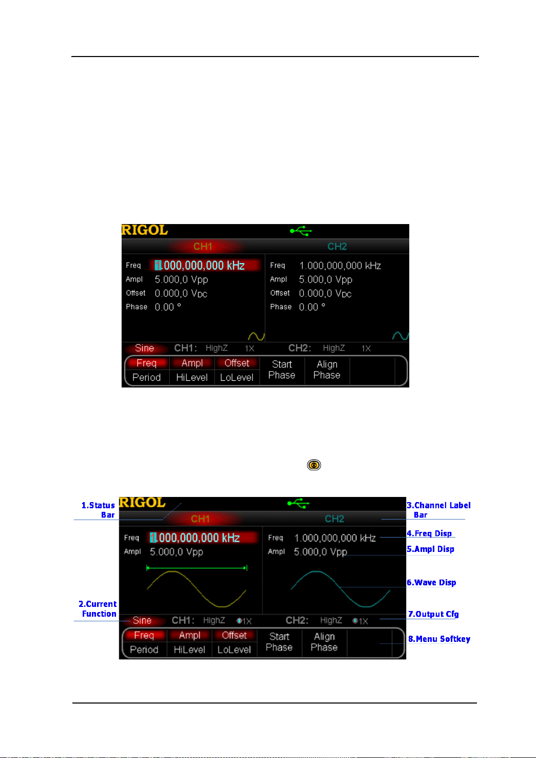
The user interface is usually shown in two modes whi ch are “Parameter” and “Graphic”.
The illustration given here will take the “Graphic” mode of the Dual-Channel Model for
example.
Parameter Mode
Figure 1-5 User Interface (Parameter Mode)
Graph Mode
In parameter mode, toggle the “Display Switch” at the upper right of the screen
to switch to the Graphic Mode.
Figure 1-6 User Interface (Graphic Mode)
User’s Guide for DG5000
1-15
Page 38

RIGOL Chapter 1 Quick Start
1. Status Bar
Indicate system status. For example, an icon
denotes that a USB flash
device has been detected.
2. Current Function
Show the current a ctiv e function. For example, “Sine” denotes that sine wave has
been selected at present.
3. Channel Label Bar
Be divided into two parts which marks the display areas of CH1 and CH2
respectively. The currently selected channel label will be highlighted.
4. Frequency Display
Display the current waveform frequency in each channel. Press corresponding
softkey Freq an d use the numeric keyboa rd or knob to modify this parameter. The
parameter that can be modified currently will be highlighted.
5. Amplitude Display
Display the current waveform amplitude in each channel. Press corresponding
softkey Ampl and use the numeric keyboard or knob to modify this parameter.
The value that can be modified currently will be highlighted.
6. Waveform Display
Display the currently selected waveform shape in each channel. The waveform of
the currently selected channel will be highlighted.
7. Output Configuration
Display the current output configuration in each channel, including “Output
resistance” and “Attenuation setting”.
8. Menu Softkey
Press any softkey to activate the corresponding function.
1-16
User’s Guide for DG5000
Page 39

Chapter 1 Quick Start RIGOL
To Rack Mount the Instrument
This generator can be mounted in a standard 19-in ch rack cabinet. Please disassemble
the cushioning material and handle before the installation.
Kit Parts List
No. Name Qty. Part Number Description
1-1 Front Panel 1 RM-DG-5-01
1-2 Support Board 1 RM-DG-5-02
1-3 Left Plate 1 RM-DG-5-03
1-4 Right Plate 1 RM-DG-5-04
1-5 Fixed Figure 2 RM-DG-5-05
2-1 M4 Screw 19 RM-SCREW-01 M4*6 Phil-Slot Pan Head Machine
Screw Nail
2-2 M6 Screw 4 RM-SCREW-02 M6*16 Phil-Slot Pan Head
Machine Screw Nail
2-3 M6 Nut 4 RM-SCREW-03 M6*5 Square Ma chine Female
Screw Contain Lock Blade
2-1 2-2 2-3
User’s Guide for DG5000
1-17
Page 40
RIGOL Chapter 1 Quick Start
Installation Tool
PH2 Phillips Screwdriver (recommended).
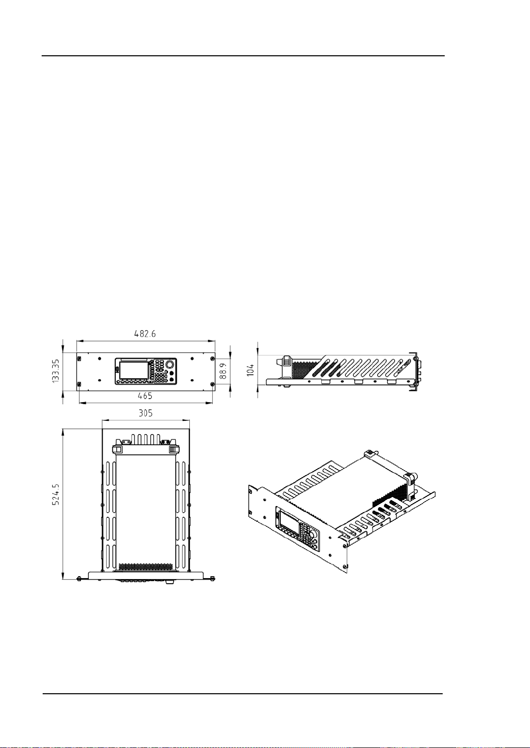
Space Require ments for Installation
The following requirements must be fulfilled by the machine cabinet in which the
instrument is mounted.
Dimension of the machine cabinet must be standard 19-inch.
At least 3U ( 133.5 mm) space shou ld be provi ded by the machine cabinet.
The depth inside the machine cabinet should not be less than 530 mm.
The dimension of the instrument after being mounted is shown below .
1-18
User’s Guide for DG5000
Page 41

Chapter 1 Quick Start RIGOL
Installation Procedure s
Only authorized operators can execute the installation operation. The instrument will
be damaged or installed in rack incorrectly if the installation is not proper.
1. Remove the handle: please grip the handle by sides, pull it outward and then
upward.
2. Install the right and left plates: align the detents of right and left plates with the
openings on the support board and insert them into the support board
respectively, then fix them with eight M4 screws.
User’s Guide for DG5000
1-19
Page 42
RIGOL Chapter 1 Quick Start
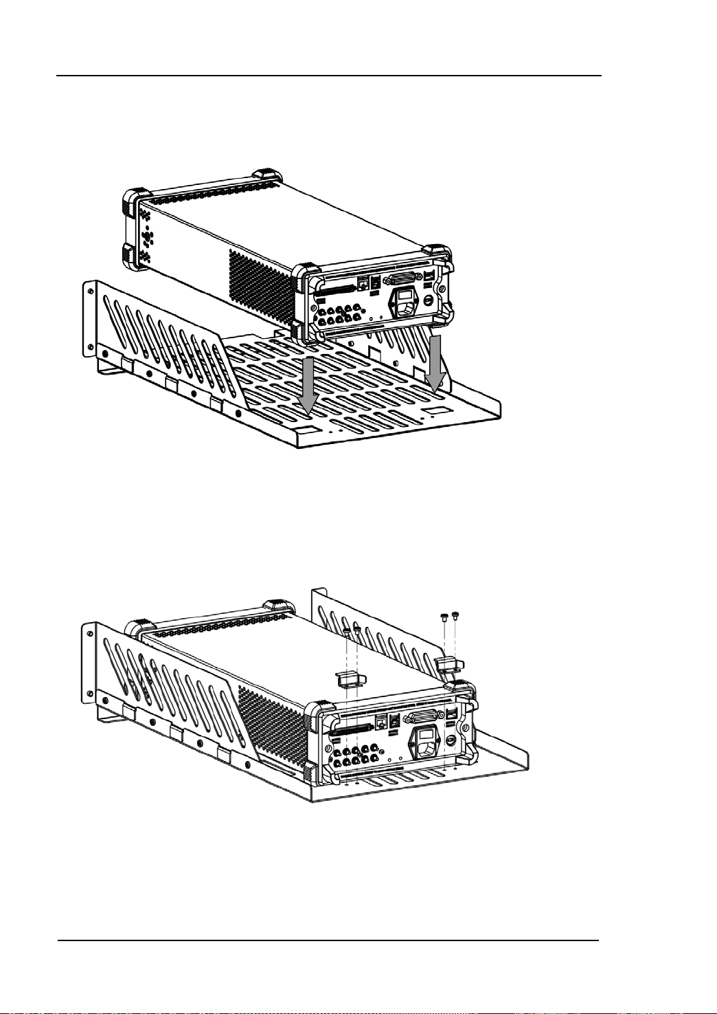
3. Place the instrument: align the protection pads of the instrument with the
corresponding holes and then place it on the Support Board.
4. Fixed the instrument: Fasten the instrument tightly on the Support Board with
two Fixed Figures and fixed it with four M4 screws.
5. Install the Front Panel: aiming the instrument front panel at the opening of the
Front Panel of the machine rack and fix them with four M4 screws.
1-20
User’s Guide for DG5000
Page 43

Chapter 1 Quick Start RIGOL
6. Load into the machine cabinet: mount the rack fixed with instrument into a
standard 19-inch machine cabinet with four M6 screws and square nuts.
7. Post-installation notice: The rack occupies a height of 3U. The holes pointed out
by the arrows are the installation holes. Note that they are aligned while
installing.
User’s Guide for DG5000
1-21
Page 44

RIGOL Chapter 1 Quick Start
To Use the Security Lock
Use a security lock to lock your generator in a desired lo cation. As shown in the picture
below, align the lock with the lock hole on t he generator and insert the lock. Turn the
key clockwise to lock the instrument and then pull the key out.
1-22
User’s Guide for DG5000
Page 45

Chapter 1 Quick Start RIGOL
To Use the Built-In Help
To get context help information about any front-panel key or menu softkey, press
Help to illuminate the k ey and then pr ess the desired key to get corresponding help.
Pressing Help twice will get the following common help.
1. View the last displayed message.
2. View error queue of the remote commands.
3. Get the help information of a key.
4. Generate a basic waveform.
5. Generate an arbitrary waveform.
6. Generate a modulated waveform.
7. Generate a frequency Sweep.
8. Generate a Burst waveform.
9. IQ (In-Phase/Quadrature) modulation.
10. Frequency hopping output.
11. Storage management.
12. Synchronize multiple Generators.
13. Seamlessly connected with the RIGOL DS.
14. Get technical support from RIGOL.
User’s Guide for DG5000
1-23
Page 46

Page 47

Chapter 2 Basic Waveform Output RIGOL
Chapter 2 Basic Waveform Output
This chapter introduces how to outp ut basic w avef orms such as Sine, Squa re, etc. The
generator can output basic wa v ef o rms f rom the sing le channe l or two channels at the
same time.
Subjects in this chapter:
To Output Sine Waveform
To Output Square Waveform
To Output Ramp Waveform
To Output Pulse Waveform
To Output Noise Waveform
Align Phase
User’s Guide for DG5000
2-1
Page 48

RIGOL Chapter 2 Basic Waveform Output
To Output Sine Waveform
To output a sine waveform from CH1 with 20 kHz frequency, 2.5 Vpp amplitude, 500
mVDC offset and 10 ° start phase.
1. Select Channel
Press CH1|CH2 to select CH1. “CH1” in Channel Label Bar will be highlighted
indicating that CH1 has been selected.
2. Select Sine Waveform
Press Sine to select Sine waveform. The key will be illuminated and the
corresponding menus display at the bottom of the screen.
3. Set the Frequency/Period
Press Freq/Period to highlight “Freq”, and then use the numeric keyboard to
input “20” and select the unit “kHz” in the pop-up menu.
Sine waveform frequency range: 1 μHz to 350 MHz.
Press the softkey again to switch to “Period”.
Selectable frequency units: MHz, kHz, Hz, mHz, μHz.
Selectable period units: sec, msec, μsec, nsec.
You can also use the knob to modify this parameter.
4. Set the Amplitude
Press Ampl/HiLevel to highlight “Ampl”, and then use the numeric keyboard to
input “2.5” and select the unit “Vpp” in the pop-up menu.
The amplitude range is limited by the “Resistance” and “Freq/Period”
settings. Please refer to the “Output Characteristic” described in
“Specifications”.
Amplitude and offset, HiLevel and LoLevel, always exist in pairs. Press the
softkey again to switch to “HiLevel”.
Selectable amplitude units: Vpp, mVpp, Vrms, mVrms, dBm (non-high
impedance).
Selectable high level units: V, mV.
You can also use the knob to modify this parameter.
5. Set the DC Voltage Offset
Press Offset/LoLevel to highlight “Offset”, and then use the numeric keyboard
2-2
User’s Guide for DG5000
Page 49

Chapter 2 Basic Waveform Output RIGOL
to input “500” and select the unit “mVDC” in the pop-up menu.
The offset range is limited by the “Resistance” and “Ampl/HoLevel”
setting. Please refer to the “Output Characteristic” described in
“Specifications”.
Amplitude and offset, HiLevel and LoLevel, always exist in pairs. Press the
softkey again to switch to “LoLevel”. Note that the low lev el should be at least
5 mV (50Ω) lower than the high level.
Selectable offset units: V
, mVDC.
DC
Selectable low level units: V, mV.
You can also use the knob to modify this parameter.
6. Set the Start Phase
Press Start Phase to high light the softkey, and then use the numeric keyboard to
input “10” and select the unit “º” in the pop-up menu.
Start Phase range: 0 º to 360 º.
You can also use the knob to modify this parameter.
7. Channel Setting
Besides the above steps, you can also configure the output parameters related t o
the channel through “Channel Setting” menu in Utility. As shown in the
following figure, the main output parame te r s (Resistance and Attenuation) of
the channel are shown at the bottom of the screen.
8. Enable the Output
Press Output of CH1 to highlight the key, which indicates the waveform output
from the [Output] connector of CH1 has been enabled. If an overload message
appears on the screen, please cut off the connection between the [Output]
connec tor and the external devices, and then press Output again to re-enable
the output.
User’s Guide for DG5000
2-3
Page 50

RIGOL Chapter 2 Basic Waveform Output
switch the output unit of the current parameters from the front
Units Switching
You can quickly
panel. For example, to transform 2 Vpp to a v alue w hose unit is Vrms, press the
key · in the numeric keyboard and then select the unit “Vrms” in the pop-up
menu. If for a Sine waveform, the transformed value is 707.1 mVrms. You will
find DG5000 is also an excellent “calculator”.
2-4
User’s Guide for DG5000
Page 51

Chapter 2 Basic Waveform Output RIGOL
T
t
Duty Cyc=t/T*100%
To Output Square Waveform
To output a square waveform from CH1 with 20 kHz frequency, 2.5 Vpp amplitude,
500 mVDC offset, 30% duty cycle and 10 ° start phase. Refer to “To Output Sine
Waveform” to configure the parameters and output. This section will only talk about
“Duty Cycle”.
What’s Duty Cycle?
Duty Cycle is defined as the percentage that the high level takes up in the whole
period.
Set the Duty Cycle
1. Press Square to select square waveform. The key will be illuminated and the
corresponding menus display at the bottom of the screen.
2. Press Duty Cycle to highlight the softkey, and then use the numeric keyboard to
input “30” and select the unit “%” in the pop-up menu.
The duty cycle range is limited by the “Freq/Period” setting.
For frequency lower than or equal to 10 MHz: 20% to 80%
For frequency greater than 10 MHz and lower than or equal to 40 MHz: 40%
to 60%
For freque ncy greater than 40 MHz: 50%
You can also use the knob to modify this parameter.
User’s Guide for DG5000
2-5
Page 52
RIGOL Chapter 2 Basic Waveform Output
T
t
Symmetry
=t/T*100%
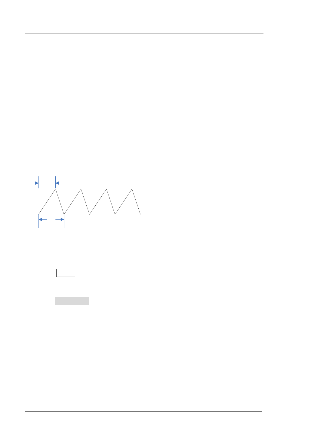
To Output Ramp Waveform
To output a ra mp w a vef orm f rom CH1 with 20 kHz frequency, 2.5 Vpp am pli tu de , 500
mV
DC offset, 80% symmetry and 10 ° start phase. Refer to “To Output Sine
Waveform” to configure the parameters and output. This section will only tal k ab out
“Symmetry”.
What’s symmetry?
Symmetry is defined as the percentage that the rising period takes up in the whole
period.
Set the Symmetry
1. Press Ramp to select ramp waveform. The key will be illuminated and the
corresponding menus display at the bottom of the screen.
3. Press Symmetry to highlight the softkey, and then use the numeric keyboard to
input “80” and select the unit “%” in the pop-up menu.
Symmetry range: 0% to 100%.
You can also use the knob to modify this parameter.
2-6
User’s Guide for DG5000
Page 53

Pulse Width
10%
50%
90%
t
Rise
t
Fall
Chapter 2 Basic Waveform Output RIGOL
To Output Pulse Waveform
To output a pulse w a ve fo rm from CH1 wit h 20 kHz frequency, 2.5 Vpp a m plit u de, 500
mVDC offset, 10 μs pulse width (20% duty cycle), 50 ns leading an d t railin g edge time
and 8 μs delay. Refer to “To Output Sine Waveform” to configure the parameters
and output. This section will only talk about “Pulse Width/Duty Cycle”, “Leading”,
“Trailing”, “Delay” and “Recover Del ay ”.
Pulse Width/Duty Cycle
Pulse Width/Duty Cycle i s defined as the time from the 50% t hresh old of a risi ng edge
amplitude to the 50% threshold of the next falling edge amplitude.
Press Pulse Width/Duty to highlight “Pulse Width”, and then use the numeric
keyboard to inpu t “10” and select the unit “μs” in the pop-up menu.
Pulse Width is li mited by the “Minimum Pulse Width” and the “Pulse Period”.
Minimum Pulse Width = 4 ns
Pulse Width ≥ Minimum Pulse Width
Pulse Width ≤ Pulse Period - Minimum Pulse Width × 2
Pulse Width and Duty Cycle are correlative. Once a parameter is changed, the
other one will be automatically changed. Press the softkey again to switch to
“Duty Cycle” (having been automatically set to 20% in this example, refer to “Set
the Duty Cycle” for manual setting). Pulse Duty Cycle is limited by the
“Minimum Pulse Width” and the “Pulse Period”.
Pulse Duty Cycle ≥ 100 × Minimum Pulse Width ÷ Pulse Period
Pulse Duty Cycle ≤ 100 × (1 - 2 × Minimum Pulse Width ÷ Pulse Period)
Selectable Pulse Width units: sec, msec, μsec, nsec.
You can also use the knob to modify this parameter.
User’s Guide for DG5000
2-7
Page 54

RIGOL Chapter 2 Basic Waveform Output
Delay
CH1 Output
CH2 Output
Leading/Trailing Edge Time
The Leading (rising) edge time is defined as the duration of the pulse amplitude rising
from 10% to 90% thr eshold, while the Trailing (falling) edge time is defined as the
duration of the pulse amplitude moving down from 90% to 10% threshold.
Press Pulse Leading (or Trailing ) to highlight the softkey, and then use the
numeric keyboard to input “50” and select the unit “ns” in the pop-up menu.
Edge Time range: 2.5 ns to 1 ms.
Selectable Leading/Trailing Edge Time units: sec, msec, μsec, nsec.
You can also use the knob to modify this parameter.
Delay
Delay is defined as the delayed time of the output of a channel relative to the output
of the other channel.
Note: The delay function is only for dual-channel models.
Press Pulse Delay to highlight the softkey, and then us e the nu meric ke y board to
input “8” and select the unit “μs” in the pop-up menu.
Delay Time range: 0 s to pulse period
Selectable Delay Time units: sec, msec, μsec, nsec.
You can also use the knob to modify this parameter.
2-8
User’s Guide for DG5000
Page 55

Chapter 2 Basic Waveform Output RIGOL
Recover Delay
The recover delay function is only for dual-channel models. Press Pulse, th e n use
to open the 2/2 menu page and press Restore, the generator will align the
delay between the two channels. Assume that CH1 and CH2 output pulse waveforms
with the same parameters. Use the oscilloscope to sample the waveforms of the two
channels and display them stably. Then, toggle the output switch of the generator.
The two waveforms display ed on the oscilloscope have a certain delay. At this point,
press Restore on the generator and the waveforms will be displayed on the
oscilloscope without any delay.
CH1
CH2
Before Restore
CH1
CH2
After Resto re
Note: For dual-channel models, the corresponding Restore is grayed out and
disabled if any of the two channels is in modulation mode.
User’s Guide for DG5000
2-9
Page 56

RIGOL Chapter 2 Basic Waveform Output
To Output Noise Waveform
To output noise waveform from CH1 with 2.5 Vpp amplitude and 500 mV
Refer to “To Output Sine Waveform” to configure the parameters and output.
DC offset.
2-10
User’s Guide for DG5000
Page 57

Chapter 2 Basic Waveform Output RIGOL
Align Phase
The align phase function is only for dual-channel models. Aligning phase is available
for the opera tion of two channels. Pressin g down this softkey w ill re-configure the two
channels, and enable the generator to output with specified frequency and start
phase.
For two signals whose frequencies are the same or in multiple, this operation will align
their phase. For example, assume a sine waveform (1 kHz, 5 Vpp, 0 °) is outputted
from CH1, while another (1 kHz, 5 Vpp, 180°) from CH2. Use an oscilloscope to
sample and display the two signals, and then toggle the channel output switch of the
generator, you will see that the waveform shown on the oscilloscope do not always
have a phase deviation of 180°.
Now, p ress Align Phase on the generator. The waveforms shown on the oscilloscope
will have a phase deviation of 180° without any adjustment of the oscilloscope.
CH1
CH2
Before Align Phase
CH1
CH2
After Align Phase
User’s Guide for DG5000
2-11
Page 58

RIGOL Chapter 2 Basic Waveform Output
NOTE: For dual-channe l models, the Align Phase menu is grayed and disabled when
any one of the two channels is in modulation mode.
2-12
User’s Guide for DG5000
Page 59

Chapter 3 Arbitrary Waveform Output RIGOL
Chapter 3 Arbitrary Waveform Output
This chapter introduces how to output built-in or user-defined arbitrary waveforms.
The generator enable to output arbitrary waveforms from the single channel or two
channels at the same time.
Subjects in this chapter:
To Enable Arbitrary Waveform
Output Mode
To Select Arbitrary Waveform
To Create New Arbitrary Waveform
To Edit Arbitrary Waveform
User’s Guide for DG5000
3-1
Page 60

RIGOL Chapter 3 Arbitrary Waveform Output
To Enable Arbitrary Waveform
Press Arb to op e n the operation me nu of arbitrary waveform.
1. Freq/Period (Sample)
Set the output “Frequency/Period” of the arbitrary waveform in “Normal” mode.
Set the sample rate when the generator sample data from external memory in
“Play” mode.
2. Ampl/HiLevel
Set the output “Amplitude/High Level” of the arbitrary waveform.
3. Offset/LoLevel
Set the output “Offset/Low Level” of the arbitrary wave form.
4. Phase
Set the “Initial Phase” of the arb i t rary waveform.
5. Align Phase
Refer to “Align Phase”.
6. Mode
Select the output mode of the arbitrar y waveform to “Normal” or “Play”.
7. Select Wform
Select arbitrary waveform stored in internal or external memories.
8. Create New
Users can def in e waveform with up to 512k points.
Note: DG5000 can output waveform with up to 128M points. F or the w ave form of
which the number of p oint s is more than 512k points, users can use the matchi ng
PC software of DG5000 to edit and download waveform to DG5000 for output.
9. Edit Wform
Edit the stored arbitrary waveform.
3-2
User’s Guide for DG5000
Page 61

Chapter 3 Arbitrary Waveform Output RIGOL
Refer to “To Output Sine Waveform” to configure the parameters and output. This
chapter will focus on “Mode”, “Sample”, “Select Waveform”, “Cr eate New ” and “Edit
Waveform”.
User’s Guide for DG5000
3-3
Page 62

RIGOL Chapter 3 Arbitrary Waveform Output
Output Mode
Press Arb Mode to set arbitrary waveform output mode to “Normal” or “Play”.
The generator adopts DDS to generate wa veform data in “Normal” mode. In this case,
you can ch ang e th e ph ase s te p of the sampling by changing the Frequency (Period).
However, the sample rate is fixed. To change the sample rate, you should use the
“Play” mode.
Normal Mode
In this mode, the generator can output internal waveforms which are defined on line
by users or downloaded from PC after edited on PC software. Waveforms stored in a
USB flash device can also be read and outputted. The output frequency ranges from 1
μHz to 50 MHz, and the sample rate is fixed at 1G Sa/s, while the number of points is
16Mpts.
As shown in the figure below, press Mode and select “Normal”, and then press
Freq/Period to change the frequency.
3-4
Figure 3-1 Arbitrary waveform output mode (Normal)
User’s Guide for DG5000
Page 63

Chapter 3 Arbitrary Waveform Output RIGOL
N
s
2
1G Sa/s
f =
82)-(N
1G Sa/s
f
s
×
=
Play Mode
The generator will enable the “Play” mode once the points of the arbitrary waveform
to be output is greater than 16 Mpts and be able to output waveform with up to 128
Mpts. In this mode, you can adjust the sample rate fs through setting the frequency
division coefficient N. The function relationship between fs and N is as follo wing:
When N≤2,
When N>2,
The range of N is from 0 to 268435456 (228).
As shown in the figure below, press Mode to select “Play”. As can be seen,
Freq/Period will change to Sample which denotes the frequency division coefficient
N. Use the numeri c key boa rd or knob to modify the parameter.
Figure 3-2 Arbitrary waveform output mode (Play)
User’s Guide for DG5000
3-5
Page 64

RIGOL Chapter 3 Arbitrary Waveform Output
To Select Arbitrary Waveform
Press Arb, use to open the 2/2 menu page, and th en press Select Wform to
select “Builtin”, “Stored Wforms” or “Volatile Wform” for arbitrary waveform output.
Built-In Waveform
10 kinds of built-in arbi trar y wave for ms ar e prov id ed by DG5000, including DC, Sinc,
Exponential Rise, Exponential Fall, ECG, Gauss, Haversine, Lorentz, Pulse and Dual
Tones.
DC
DG5000 can output DC signal with amplitude ranging from -10 V to 10 V. T he figur e
below shows a DC waveform.
Sinc
The figure below shows a Sinc waveform.
3-6
User’s Guide for DG5000
Page 65

Chapter 3 Arbitrary Waveform Output RIGOL
Exponential Rise
The figure below shows an Exponential Rise waveform.
Exponential Fall
The figure below shows an Exponential Fall waveform.
ECG
The figure below shows an ECG waveform.
User’s Guide for DG5000
3-7
Page 66

RIGOL Chapter 3 Arbitrary Waveform Output
Gauss
The figure below shows a Gauss waveform.
Haversine
The figure below shows a Haversine waveform.
Lorentz
The figure below shows a Lorentz waveform.
3-8
User’s Guide for DG5000
Page 67

Chapter 3 Arbitrary Waveform Output RIGOL
Pulse
The figure below shows a simulated Pulse waveform.
The Pulse mentioned here can be configured by setting the parameters “Pulse
Width/Duty Cycle”, “Leading” and “Trailing”.
Pulse Width/Duty Cy cle: The minimum Pulse Wi dth is related to the current edge
time, ranging from 4 ns to “Pulse Period - 12 ns”, while Duty Cycle ranges from
0% to 100%.
Leading: ranges from 2.5 ns to 1.9531 ks, and relates to the pulse period, pulse
width and the trailing edge.
Trailing: ranges from 2.5 ns to 1.9531 ks, an d relates to th e pulse per iod, pulse
width and the leading edge.
User’s Guide for DG5000
3-9
Page 68
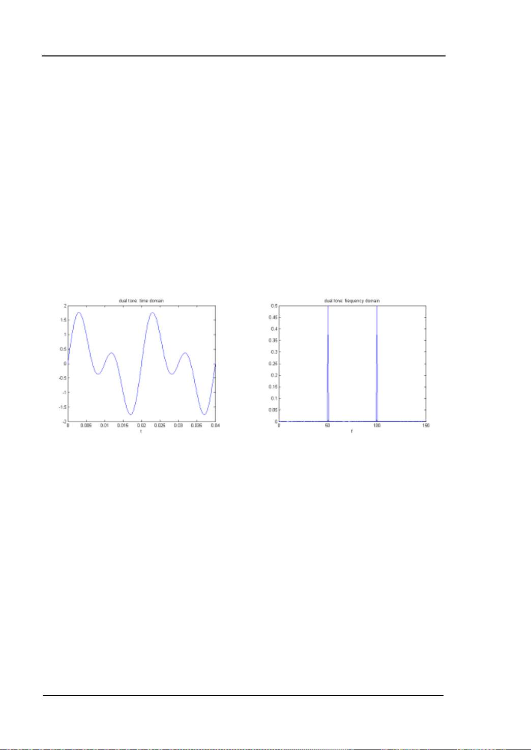
RIGOL Chapter 3 Arbitrary Waveform Output
Dual Tones
The Dual Tones signal can be used to measure the inter-modulation distortion
characteristic of non-linear devices (such as mixer or amplifier). Inter-Modulation
Distortion (IMD) will be generated when a non-linear device with multiple input
frequencies disturbs the adjacent channels or causes unexpected output at other
frequencies. DG5000 enables to generate such Dual Tones that the Inter-Modulation
Distortion from it can be measured by a Spectrum Analyzer. When measuring the
Inter-Modulation Distortion generated by the device under test (DUT), this signal can
be used as the measurement source.
The f igures below are the oscillograms of Dual Tones generated by DG5000 in the
time domain and the fre q ue ncy domain respectively.
3-10
User’s Guide for DG5000
Page 69

Chapter 3 Arbitrary Waveform Output RIGOL
Stored Waveform
Select arbitrary wav efor ms st ore d in internal non-volatile memory (C Disk) or external
memories (D Di s k or E Disk).
Press this softkey to enter the Store/Recall Interface and the Store/Recall key on
the front panel is illuminated. Please select and read the desired arbitrary waveform
file. For more details, please refer to “
memory will be changed after the file is read. To return arbitrary waveform setting
interface, press the Arb.
Store and Recall”. Waveform data in volatile
Volatile Waveform
Select arbitrary waveform currently stored in the vol atile m emory. Note that this menu
would be unavailable if there is no waveform data in volatile memory currently. To fill
up the volatile memory, you can create a waveform through “Create New” or select a
waveform from “Built-In” or “Stored Wforms”.
User’s Guide for DG5000
3-11
Page 70

RIGOL Chapter 3 Arbitrary Waveform Output
To Create New Arbitrary Waveform
Press Arb, use to open the 2/2 menu page, and then press Create New to
open the arbitr ary waveform create int e rface.
1. Cycle Period
Press this softkey and use the numeric ke yboard or knob to set the cycle perio d of
the new waveform. The set ting r ange is from 20 ns to 1 Ms. Note that the time of
the last point that can be defined should be less than the cycle period.
2. High VLimit
Press this softke y and use the numeric key board or k nob to set the hi gher level of
the new waveform. The upper limit of this level is +5 V (50 Ω), and the lower limit
is the minimum which is greater than current setting of the “Low VLimit”.
3. Low VLimit
Press this softkey and use the numeric keyboard or knob to set the lower level of
the new waveform. The lower limit of this le vel is -5 V (50 Ω), a nd the u pper limit
is the maximum which is lower than current setting of the “High VLimit”.
4. Init #Points
When creating a new waveform, the waveform editor will automatically create a
waveform with two points. By default, point 1 is located at 0 seconds and point 2
at half of the spe cified cycle period. In ad dition, the voltages of the two points are
equal to the specified “Low VLimit”.
Press this softkey and use the numeric keyb oa r d or the knob to set the initial
points of the new wa vefo rm. The initial points of the arbit rary wavef orm can be up
to 524 488 (512 kpts) points. If in need, you can “Insert Point” or “Delete
Point” waveform points later.
5. Interp
Press this softkey to enable or disable the interpolation between the defined
waveform points.
Off: Disable the interpolation. The waveform editor will hold a constant
voltage level between two points and create a step waveform.
Linear: The waveform editor will automatically connect the two def ined
points with a straight line.
3-12
User’s Guide for DG5000
Page 71

Chapter 3 Arbitrary Waveform Output RIGOL
Sinc: The waveform editor will automatically connect the two points with a
smooth curve . Notice that, the interpolation point v oltage ma y be w ithout the
arbitrary waveform level limit and an une xpected cu rve w ill be a cqui red if the
defined point voltage is the same as High VLimit or Low VLimit. Thus, try
not to define the point voltage as the High VLimit or Low VLimit values.
6. Edit Points
Define a waveform by specifying the time and voltage of each waveform point.
Press this softkey to enter the “Edit Points” interface.
PointID: Set the ID of the point to be edited. The default is 1. You can use
the numeric keyboard or knob to modify this parameter.
Time: Set the ti me of the current point. This setting is limited by the time of
the previous and the next points. Note that the time of point 1 is fixed at 0 s.
Voltage: Set the voltage of the current point in mV or V. The range of the
voltage value is li mited by the “High VLimit” and “Low VLimit” specified in
the initialization. Note that the wavef orm editor wi ll automatically conne ct the
last point to the voltage level of the first point to create a continuous
waveform.
Insert Point: Insert a waveform point at the middle position of the currently
edited point a nd the next edited point.
Delete Point: Delete the current point from the waveform and connect the
remaining points using the current interpolation method. Note that point 1
cannot be deleted.
7. Edit Block
Define a waveform by editing the time and voltage of the start and end points
and automatically setting the points between them through linear interpolation.
Press Interp to select “Linear”, and then press this softkey to enter the “Edit
Block” interface.
X1: Set the start point (Time) of the block. Note that this value should be
equal to or less than the “Init Points” and X2.
Y1: Set the voltage of the start point in mV or V.
X2: Set the end poi nt (Time) of the blo ck. Note that this value should be less
than or equal to the “Init Points” And be greater than or equal to X1.
Y2: Set the voltage of the end point in mV or V.
Execute: Edit the points within the start and end points according to the
current setting.
Delete: Delete the points that can be edited between X1 and X2 and
User’s Guide for DG5000
3-13
Page 72

RIGOL Chapter 3 Arbitrary Waveform Output
connect the start and end points using the current interpolation method.
Note that point 1 cannot be deleted.
8. Save
The currently created waveform is stored in the volatile memory. When creating a
new waveform, the previous waveform in volatile memory will be overwritten.
Press this softkey to enter the file storage interface (refer to “Store and Recall”).
Users can store the edited waveform into internal memory (C Disk) or external
memories (D Disk or E Disk) of the instrument.
Tips
Users can store the waveform edited by PC software into the local memory of
the instrument through the following two methods:
Use SCPI commands (more information, see “
Programm ing Guide”
of this
generator).
For waveform with greater than 16 kpts:
:TRACe:DAC VOLATILE16,<flag>,<len>,<binary_block_data>
For waveform with less than 16 kp t s:
:TRACe:DAC VOLATILE,<binary_block_data>
Use the file management system to transfer f il es from USB flash device
(recognized as D Disk or E Disk in the generator) to internal memory (C
Disk) of the instrument.
3-14
User’s Guide for DG5000
Page 73
Chapter 3 Arbitrary Waveform Output RIGOL
Edit Points
The following example introduces how to create an arbitrary waveform which meets
with the following conditions by using “Edit Points”.
Parameter Value
Cycle Period 12 μs
High VLimit 4 V
Low VLimit -2 V
Interpolation Linear
Point 1 0 s, 0 V
Point 2 4 μs, 4 V
Point 3 8 μs, 0 V
Point 4 10 μs, -2 V
Operating Procedures:
1. Press Arb, use to open the 2/2 menu page, and then press Create New
Cycle Period, use the numeric keyboa rd t o in put “12” and select the unit “μs”
in the pop-up menu.
2. Press High VLimit, use the nume ric k eyb oard t o in put “4” and select the unit “V”
in the pop-up menu.
3. Press Low VLimit, use the numeric keyboa rd to in put “-2” and select the unit “V”
in the pop-up menu.
4. Press Init #Points, use the numeric keyboard to input “4” and then press OK.
Note that a level line of -2 V appears.
5. Press Interp to select “Linear”.
6. Press Edit Point s to enter the “Edit Point” interface.
1) Press PointID to define the first point (default time is 0). Press Voltage and
User’s Guide for DG5000
3-15
Page 74
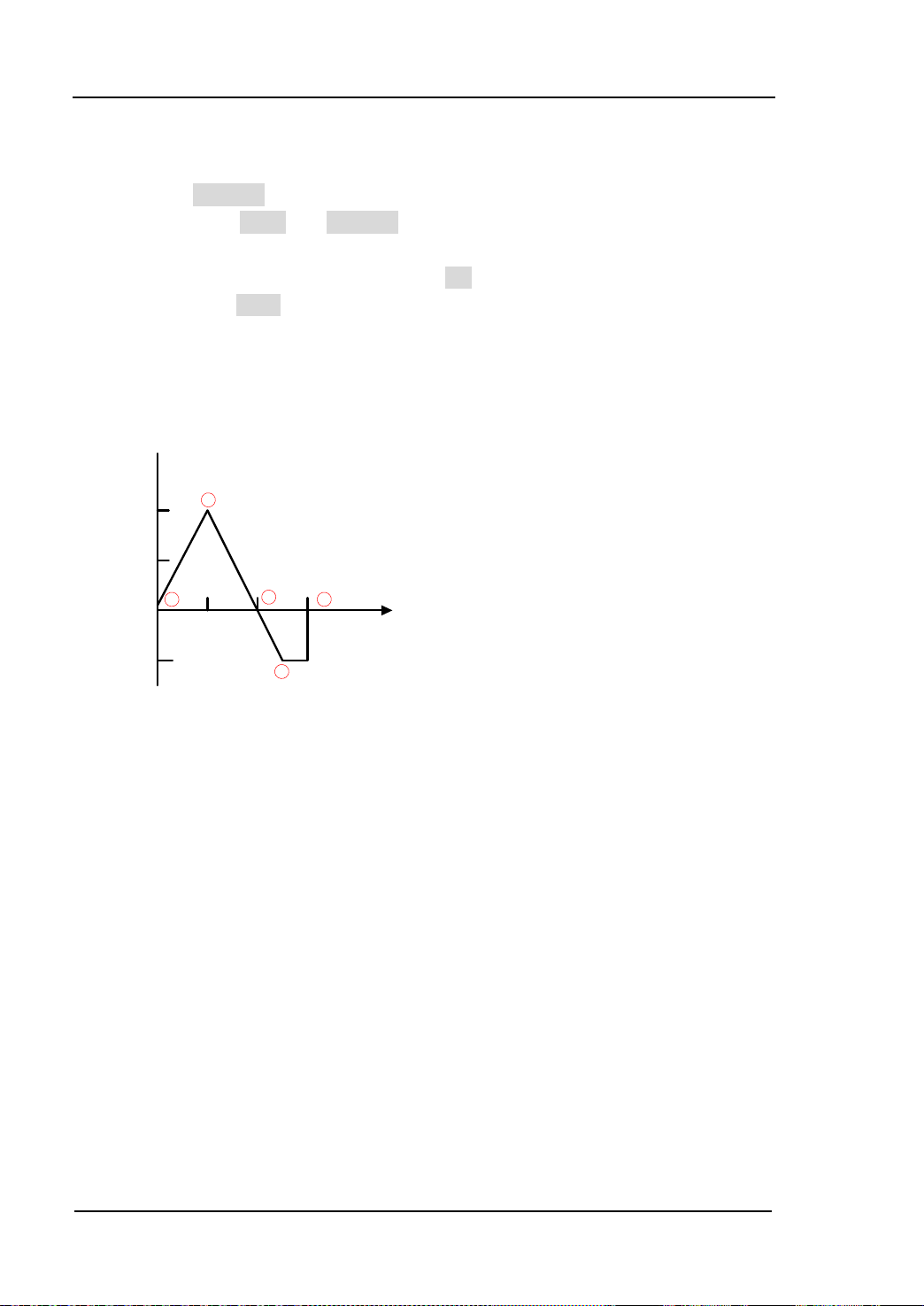
RIGOL Chapter 3 Arbitrary Waveform Output
V
μs
4
2
0
-2
4 8 12
2
1
3
4
1
use the numeric keyboard to input “0” and select the unit “V” in the pop-up
menu.
2) Press PointID again and use the numeric ke yboar d or k nob to select point 2.
Then press Time and Voltage respectively to define point 2 as 4 μs and 4 V.
3) Define point 3 and point 4 according step 2).
4) After all the points are edited, press OK to return to the upper level menu,
then press Save to enter the file storage interface (refer to “Store and
Recall”) and save the edit ed waveform.
7. View the edi ted wavefo rm.
Note: As can be seen from the above figure, the waveform editor will always connect
from the first point to the voltage level of the last point to create a continuous
waveform.
3-16
User’s Guide for DG5000
Page 75

Chapter 3 Arbitrary Waveform Output RIGOL
Edit Block
The following example introduces how to create an arbitrary waveform which meets
the following conditions with the following conditions met by using “Edit Block”.
Parameter Value
Cycle Period 12 μs
High VLimit 4 V
Low VLimit -2 V
Interpolation Linear
Start 2, 4 V
End 4, -2 V
Operating Procedures:
1. Press Arb, use to open the 2/2 menu page, and then press Create New
Cycle Period, use the numeri c k eyboar d t o in put “12” and select the unit “μs”
in the pop-up menu.
2. Press High VLimit, use the n ume ric ke yboa rd t o input “4” and select the unit “V”
in the pop-up menu.
3. Press Low VLimit, use the numeric keyboa rd to in put “-2” and sele ct the unit “V”
in the pop-up menu.
4. Press Init #Points, use the numeric keyboard to input “4” and then press OK.
Note that a level line of -2 V appears.
5. Press Interp to select “Linear”.
6. Press Edit Block to enter the “Edit Block” interface.
1) Press X1 and use the numeric keyboard to input “2”. Then press Y1 and use
the numeric keyboard to i nput “4” and select the u nit “V” in the pop-up menu.
Use the same method to set X2 and Y2.
2) Press Excute to apply the set ting defined in step 1). The waveform editor will
User’s Guide for DG5000
3-17
Page 76
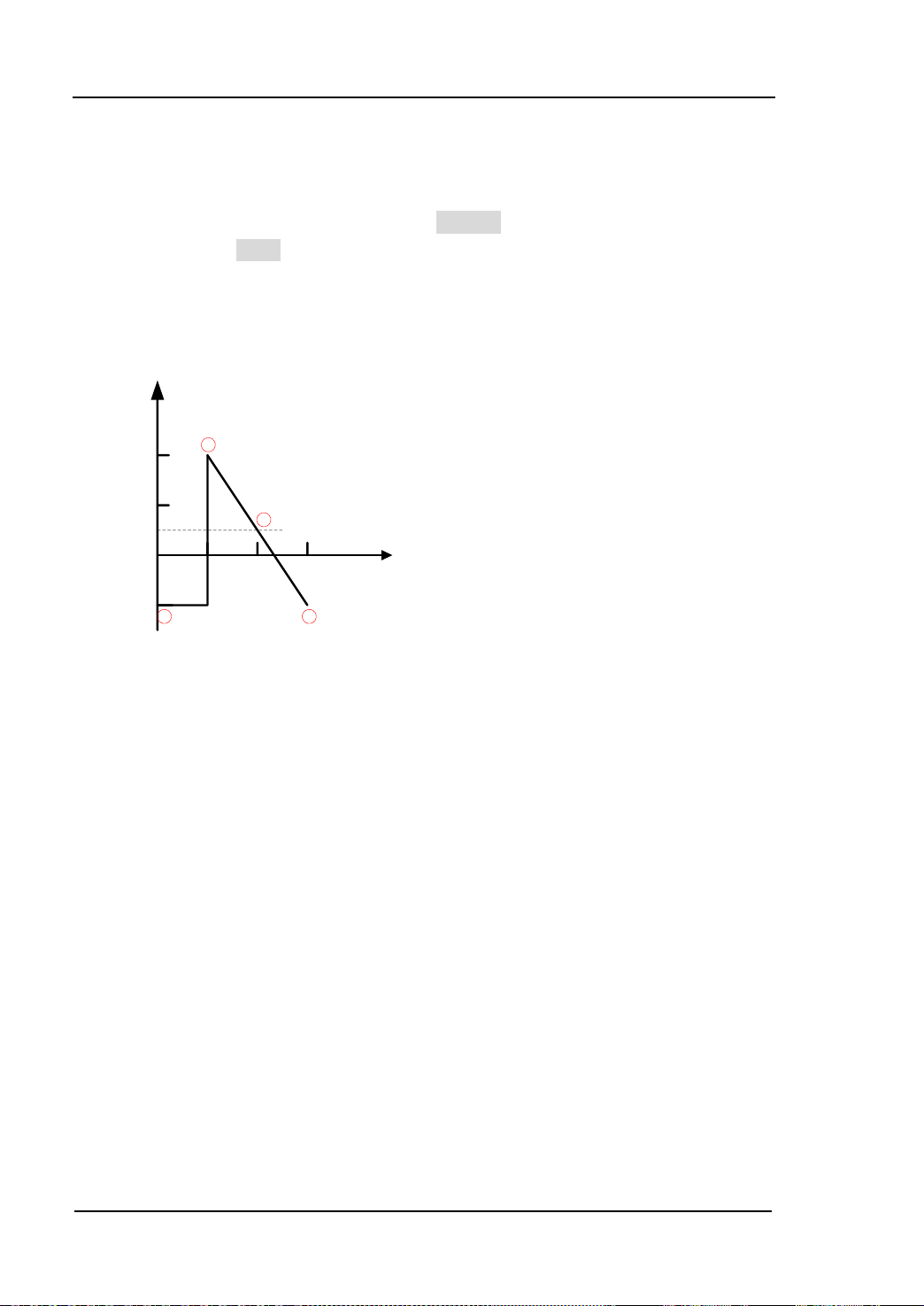
RIGOL Chapter 3 Arbitrary Waveform Output
V
μs
4
2
0
-2
4 8 12
2
1
3
4
automatically use straight lines to connect the start point (point 2, the leve l is
4 V) with the stop point (point 4, the level is -2 V) and automatically generate
point 1 and point 3 to create a continuous waveform.
3) After all the points are edited, press Return to return to the upper lev el menu,
then pres s Save to enter the f i le storage interface (refer to “Store and
Recall”) and save the edited waveform.
7. View the edi ted wavefo rm.
Note: As can b e seen from the abo v e fi gure, after the start point (point 2) and stop
point (point 4) are inserted numerical values in the current interpolation method, the
waveform editor will automatically generate point 1 and point 3 to create a con tinuous
waveform.
3-18
User’s Guide for DG5000
Page 77

Chapter 3 Arbitrary Waveform Output RIGOL
To Edit Arbitrary Waveform
Arbitrary wa vef orms sto red both in volatile memory and non-volatile memories can be
recalled and re-edited.
Press Arb and use to open the 2/2 menu page, then press Edit Wform to
open waveform editing menu. Note that, only “Select Wform” is new in this menu
compared to Creat e New, which will be introduced in this section. For other menu
functions and operations, please refer to “
Press Edit W form Select Wform to select the waveform to be edited.
1. To Edit Built-In waveforms
Select a waveform fr o m the built-in waveforms to edit. You can store the edited
waveform without overwriting the selected built-in waveform.
2. To Edit Stored Waveforms
Select a waveform from internal non-volatile memory (C Disk) or exter n a l
memories (D Disk or E disk) to edit. You can overwrite the old waveform or save it
as a new file.
3. To Edi t W a v e fo rm in Volatile Memory
Select waveform stored in current volatile memory to edit. The previous data in
the volatile memory would b e overwritten by t he new wavef orm data. You can
also save it into the non-volatile memory.
To Edit Arbitrary Waveform”.
User’s Guide for DG5000
3-19
Page 78

Page 79

Chapter 4 Common Modulation Output RIGOL
Chapter 4 Common Modulation Output
DG5000 can output versatile modulated waveforms with modulation types of analog
modulation (AM, FM, PM), digital modulation (ASK, FSK, PSK) and pulse modulation
(PWM). The generator provides a variety of internal modulating waveform sources
and also accepts external modulating signal from [Mod In] or [ExtTrig] connector at
the rear panel. The modulated waveforms can be output from the single channel or
the two channels at the same time.
Subjects in this chapter:
Amplitude Modulation (AM)
Frequency Modulation (FM)
Phase Modulation (PM)
Amplitude Shift Keying (ASK)
Frequency Shift Keying (FSK)
Phase Shift Keying (PSK)
Pulse Width Modulation (PWM)
User’s Guide for DG5000
4-1
Page 80

RIGOL Chapter 4 Common Modulation Output
Amplitude Modulation (AM)
An AM (Amplitude Modulation) modulated waveform consists of carri er waveform and
modulating waveform. The amplitude of the carrier waveform varies with the
instantaneous voltage of the modulating waveform.
To Select AM Modulation
Press Mod Type AM to enable AM function.
When Mod is enabled, Sweep or Burst will be disabled automatically (if
enabled currently).
After AM is enabled, the instrument will generate AM wavefor m with the current
specified carrier and modulating waveform.
To Select Carrier Waveform Shape
AM carrier waveform shape could be Sine, Square, Ramp or Arbitrary waveform. The
default is Sine.
Press the front panel key Sine, Square, Ramp or (Arb Select Wform) to
select a desired carrier waveform shape.
Pulse (basic waveform), Noise and DC could not be used as carrier waveform.
To Set Carrier Frequency
After the carrier waveform shape is selected, you can press Freq/Period to highlight
“Freq”, and then use the numeric keyboard or knob to input desired freque nc y value.
The available carrier frequency varies with different carrier waveforms.
Sine: 1 μHz to 350 MHz
Square: 1 μHz to 120 MHz
Ramp: 1 μHz to 5 MHz
Arbitrary wav e fo rm: 1 μHz to 50 MHz
4-2
User’s Guide for DG5000
Page 81

Chapter 4 Common Modulation Output RIGOL
-6 V
0 V
+6 V
To Select Modul ating Wavefor m Source
Press Mod Source to select “Int” or “Ext” modulating waveform source.
1. Inter nal Source
When internal modulatio n source is selected, press Shape to select Sine, Squa re,
Triangle, UpRamp , DnRa m p, N oise or A rb as m odulat ing w av efo rm. The defaul t i s
Sine.
Square: Duty Cycle is 50%.
Triangle: Symmetry is 50%.
UpRamp: Symmetry is 100%.
DnRamp: Symmetry is 0%.
Arb: When the current arbitrary waveform is selected as the modulating
waveform, the gen erator automatically limits the arbitrary waveform length
as 2 kpts through samp ling.
Notice that, Noise could be used as modulating waveform but not carrier
waveform.
2. External Source
When external mod ulat ion s ou rce is selected, the Shape menu will be grayed out
and disabled. The generator accepts the external modulating signal f rom the [Mod
In] connector at the rear panel. The AM modulation amplitude is controlled by the
±6 V signal level of the connector.
To Set Modulating Wave form Frequency
When internal modulation source is selec ted, press AM_Freq to set the modulating
waveform frequency.
Input the desired frequency value using the numeric keyboard or knob.
The modulating waveform frequency ranges from 2 mHz to 50 kHz, and the
User’s Guide for DG5000
4-3
Page 82

RIGOL Chapter 4 Common Modulation Output
default value is 100 Hz.
Notice that, this menu will be grayed out and disabled when external modulation
source is selected.
To Set Modulation Depth
Modulation depth expressed as a percentage indicates the amplitude vibration degree.
The AM modulation depth ranges from 0% to 120%. Press AM Depth to set AM
modulation depth.
When the modulation depth is 0%, the output amplitude is the half of the
specified value.
When the modulation depth is 100%, the output amplitude is equal to the
specified value.
When the modulation depth is higher than 100%, the output of the instrument
will not exceed 10 Vpp (The load is 50 Ω).
When external source is selected, AM modulation amplitude is also controlled by the
±6 V signal level of the [Mod In] connector at the rear panel. For example, if the
modulation depth is 100%, the output amplitude is the maximum when the
modulating signal level is +6 V and the minimum when the level is -6 V.
4-4
User’s Guide for DG5000
Page 83

Chapter 4 Common Modulation Output RIGOL
Frequency Modulation (FM)
A FM (Frequency Modulation) modulated waveform consists of carrier waveform and
modulating waveform. The frequency of the carrier waveform varies with the
instantaneous voltage of the modulating waveform.
To Select FM Modulation
Press Mod Type FM to enable FM function.
When Mod is enabled, Sweep or Burst will be disabled automatically (if
currently enabled).
After FM is enabled, the instrument will generate FM waveform with the currently
specified carrier and modulating waveform.
To Select Carrier Waveform Shape
FM carrier waveform shape could be Sine, Square, Ramp or Arbitrary waveform. The
default is Sine.
Press the front panel key Sine, Square, Ramp or (Arb Select Wform) to
select a desired carrier waveform shape.
Pulse (basic waveform), Noise and DC could not be used as carrier waveform.
To Set Carrier Frequency
After the carrier waveform shape is selected, press Freq/Period to highlight “Freq”,
and then use the numeric keyboard or knob to input desired frequency value. The
available carrier frequency varies with different carrier waveforms.
Sine: 1 μHz to 350 MHz
Square: 1 μHz to 120 MHz
Ramp: 1 μHz to 5 MHz
Arbitrary wav e fo rm: 1 μHz to 50 MHz
User’s Guide for DG5000
4-5
Page 84

RIGOL Chapter 4 Common Modulation Output
-6 V
0 V
+6 V
To Select Modul ating Wavefor m Source
Press Mod Source to select “Int” or “Ext” modulating waveform source.
1. Inter nal Source
When internal modulation source is selected, press Shape to select Sine, Square,
Triangle, UpRamp , DnRa m p, N oise or A rb as m odulat ing wa v efo rm. The default is
Sine.
Square: Duty Cycle is 50%.
Triangle: Symmetry is 50%.
UpRamp: Symmetry is 100%.
DnRamp: Symmetry is 0%.
Arb: When the current arbitrary waveform is selected as the modulating
waveform, the generator automatically limits the arbitrary waveform length
as 2 kpts through sampl i ng.
Notice that, Noise could be used as modulating waveform but not carrier
waveform.
2. External Source
When external modulat ion s ource is selected, the Shape menu will be grayed out
and disabled. The generator accepts the external modulating signal from the [Mod
In] connector at the rear panel. The frequency deviation is controlled by the ±6 V
signal level of the connector.
To Set Modulating Wave form Frequency
When internal modulation source is selected, press FM_Freq to set the modulating
waveform frequency.
Input the desired frequency value using the numeric keyboard or knob.
The modulating waveform frequency ranges from 2 mHz to 50 kHz, and the
default value is 100 Hz.
Notice that, this menu will be grayed out and disabled when external modulation
source is selected.
4-6
User’s Guide for DG5000
Page 85

Chapter 4 Common Modulation Output RIGOL
To Set Frequency Deviation
Press Deviation to set the frequency deviation of the modulating waveform
frequency relative to the c arrie r waveform frequency.
The frequency deviation must be less than or equal to the carrier waveform
frequency.
The sum of frequency devi ation and ca rrier fre quenc y must be less than or equal
to the sum of upper limit of current carrier frequenc y and 1 kHz.
When external source is selected, frequency deviation is controlled by the ±6 V signal
level of the [Mod In] connector at the rear panel. For example, if the frequency
deviation is set as 1 kHz, +6 V signal level corresponds to a 1 KHz increase in
frequency. Lower external sig nal level generates less deviation, and negative signal
level will reduce the frequency below the carrier waveform frequency.
User’s Guide for DG5000
4-7
Page 86

RIGOL Chapter 4 Common Modulation Output
Phase Modulation (PM)
A PM (Phase Modulation) modulated waveform consists of carrier waveform and
modulating waveform. The phase of the carrier waveform varies with the
instantaneous voltage of the modulating waveform.
To Select PM Modulation
Press Mod Type PM to enable PM function.
When Mod is enabled, Sweep or Burst will be automatically disabled (if
currently enabled).
After PM is enabled, t he in strument will generate PM waveform with the currently
specified carrier and modulating waveform.
To Select Carrier Waveform Shape
PM carrier waveform shape could be Sine, Square, Ramp or Arbi tr ary w avef or m. The
default is Sine.
Press the front panel key Sine, Square, Ramp or (Arb Select Wform) to
select desired carrier waveform shape.
Pulse (basic waveform), Noise and DC could not be used as carrier waveform.
To Set Carrier Frequency
After the carrier waveform shape is selected, press Freq/Period to highlight “Freq”,
and then use the numeric keyboard or knob to input desired frequency value. The
available carrier frequency varies with different carrier waveforms.
Sine: 1 μHz to 350 MHz
Square: 1 μHz to 120 MHz
Ramp: 1 μHz to 5 MHz
Arbitrary wav e fo rm: 1 μHz to 50 MHz
4-8
User’s Guide for DG5000
Page 87

Chapter 4 Common Modulation Output RIGOL
-6 V
0 V
+6 V
To Select Modul ating Wavefor m Source
Press Mod Source to select “Int” or “Ext” modulating waveform source.
1. Inter nal Source
When internal modulation source is selected, press Shape to select Sine, Square,
Triangle, UpRamp , DnRa m p, N oise or A rb as m odulat ing w av efo rm. The defaul t i s
Sine.
Square: Duty Cycle is 50%.
Triangle: Symmetry is 50%.
UpRamp: Symmetry is 100%.
DnRamp: Symmetry is 0%.
Arb: When the current arbitrary waveform is selected as the modulating
waveform, the generator automatically limits the arbitrary waveform length
as 2 kpts through samp ling.
Notice that, Noise could be used as modulating waveform but not carrier
waveform.
2. External Source
When external modulat ion s ource is selected, the Shape menu will be grayed out
and disabled. The generator accepts the external modulating signal f rom the [Mod
In] connector at the rear panel. The phase deviation is controlled by the ±6 V
signal level of the connector.
To Set Modulating Wave form Frequency
When internal modulation source i s selected, press PM_Freq to set the modulating
waveform frequency.
Input the desired frequency value using the numeric keyboard or knob.
The modulating waveform frequency ranges from 2 mHz to 50 kHz, and the
User’s Guide for DG5000
4-9
Page 88

RIGOL Chapter 4 Common Modulation Output
default value is 100 Hz.
Notice that, this menu will be grayed out and disabled when external modulation
source is selected.
To Set Phase Deviation
Press Deviation to set the deviation of the modulating waveform phase r elative to
the carrier waveform phase.
Input the desired phase using the numeric keybo ard or knob.
The phase deviation ranges from 0º to 360º.
When external source is selected, phase deviation is controlled by the ±6 V signal
level of the [Mod In] connector at the rear panel. For exa mple , if the phase deviation
is set as 180º, +6 V signal level corresponds to a 180º phase change. Lower external
signal level generates less deviation.
4-10
User’s Guide for DG5000
Page 89

Chapter 4 Common Modulation Output RIGOL
Amplitude Shift Keying (ASK)
When using ASK (Amplitude Shift Keying) modulation, you can configure the
generator to make its output amplitude “shift” between two preset amplitude values
(“carrier amplitude” and “modulating amplitude”). The “shift” rate (ASK Rate) is
determined by the signal l evel inside the instrument or from t he [Ext Trig] connector at
the rear panel.
To Select ASK Modulation
Press Mod Type ASK to enable ASK function.
When Mod is enabled, Sweep or Burst will be disabled automatically (if
enabled currently).
After ASK is enabled, the instrument will generate ASK waveform with the
currently specified carrier and modulating waveform.
To Select Carrier Waveform Shape
ASK carrier wavef orm sha pe coul d be Sin e, Squa re, Ram p or arbitrary waveform. The
default is Sine.
Press the front panel key Sine, Square, Ramp or (Arb Select Wform) to
select desired carrier waveform shape.
Pulse (basic waveform), Noise and DC could not be used as carrier waveform.
To Set Carrier Amplitude
After selectin g ca rrier w a ve form sha pe, p ress Ampl/HiLevel to highlight “Ampl”, and
then use the numeric keyboard or knob to input desired amplitude. The available
amplitude range is limited by Resistant and Freq/Period. Please refer to the
“Output Characteristic” described in “
Specifications”.
User’s Guide for DG5000
4-11
Page 90

RIGOL Chapter 4 Common Modulation Output
To Select Modul ating Wavefor m Source
Press Mod Source to select “Int” or “Ext” modulating waveform source.
1. Inter nal Source
When internal source is selected, the modulating waveform is set as a Square with
50% duty cycle, and the “shift” rate of the output amplitude between “carrier
amplitude” and “modulation amplitude” is determined by “ASK Rate”.
2. External Source
When external source is selected, the generator acce pts the external modulating
signal from the [ExtTrig] connector (as shown in the picture bellow) at the rear
panel.
Notice that, the [ExtTrig] connector used to control ASK modulation externally is
different from the [ModIn] connector used to control AM/FM/PM modulation
externally. In ASK modulation, [ExtTrig] has an adjustable edge polarity.
To Set ASK Rate
When internal source is selected, press ASK Rate to set the “shift” rate at which the
output amplitude shifts between “carrier amplitude” and “modulation amplitude”.
Input the desired frequency value using numeric keyboard or knob.
The available frequency ra nges from 2 mHz to 1 MHz, and the default value is 100
Hz.
Notice that, this menu will be grayed out and disabled when external source is
selected.
4-12
User’s Guide for DG5000
Page 91

Chapter 4 Common Modulation Output RIGOL
To Set Modula ting Amplitude
Press ModAmp to set the modulating amplitude.
Input the desired amplitude value using numeric keyboard or knob.
The available a mplitude (High Z) ranges from 0 V to 10 V, and the def ault v alue is
2 V.
To Set Modulating Polarity
Press Polarity to select the “Positive” or “Negative” of the modulating waveform to
control the output amplitude.
When internal modulation is selected, if the polarity is “positive”, logic high of the
modulating waveform amplitude corresponds to output of the greater of the two
amplitudes (modulating amplitude an d carrier amplitude), while logic low corresponds
to output of the smaller amplitude; if the polarity is “negative”, the situation is the
opposite.
When external modulation is selected, if the polarity is “positive”, logic high of the
input corresp onds to output of the greater of the two amplitudes (modulating
amplitude and carrier amplitude), while lo gic low correspon ds t o output of the smaller
amplitude; if the polarity is “negative”, the situation is the opposite.
User’s Guide for DG5000
4-13
Page 92

RIGOL Chapter 4 Common Modulation Output
Frequency Shift Keying (FSK)
When FSK (Frequency Shift Keying) modulation is selected, you c an configure the
generator to make its output frequency “shift” between two preset frequencies
(“carrier frequency” and “hop frequency”). The “shift” frequency (FSK Rate) is
determined by the signal l evel inside the instrument or from t he [ExtTrig] connector at
the rear panel.
To Select FSK Modulation
Press Mod Type FSK to enable FSK fu nction.
When Mod is enabled, Sweep or Burst will be automatically disabled (if
enabled currently).
After FSK is enabled, the instrument will generate FSK waveform with the
currently specified carrier and modulating waveform.
To Select Carrier Waveform Shape
FSK carrier waveform shape could be Sine, Square, Ramp or arbitrary waveform, and
the default is Sine.
Press the front panel key Sine, Square, Ramp or (Arb Select Wform) to
select desired carrier waveform shape.
Pulse (basic waveform), Noise and DC could no t b e used as carrier waveform.
To Set Carrier Frequency
After the carrier waveform shape is selected, you can press Freq/Period to highlight
“Freq”, and then use the numeric keyboard or knob to input desire d f reque nc y value.
The available carrier frequency varies with different carrier waveforms.
Sine: 1 μHz to 250 MHz
Square: 1 μHz to 120 MHz
Ramp: 1 μHz to 5 MHz
Arbitrary wav e fo rm: 1 μHz to 50 MHz
4-14
User’s Guide for DG5000
Page 93
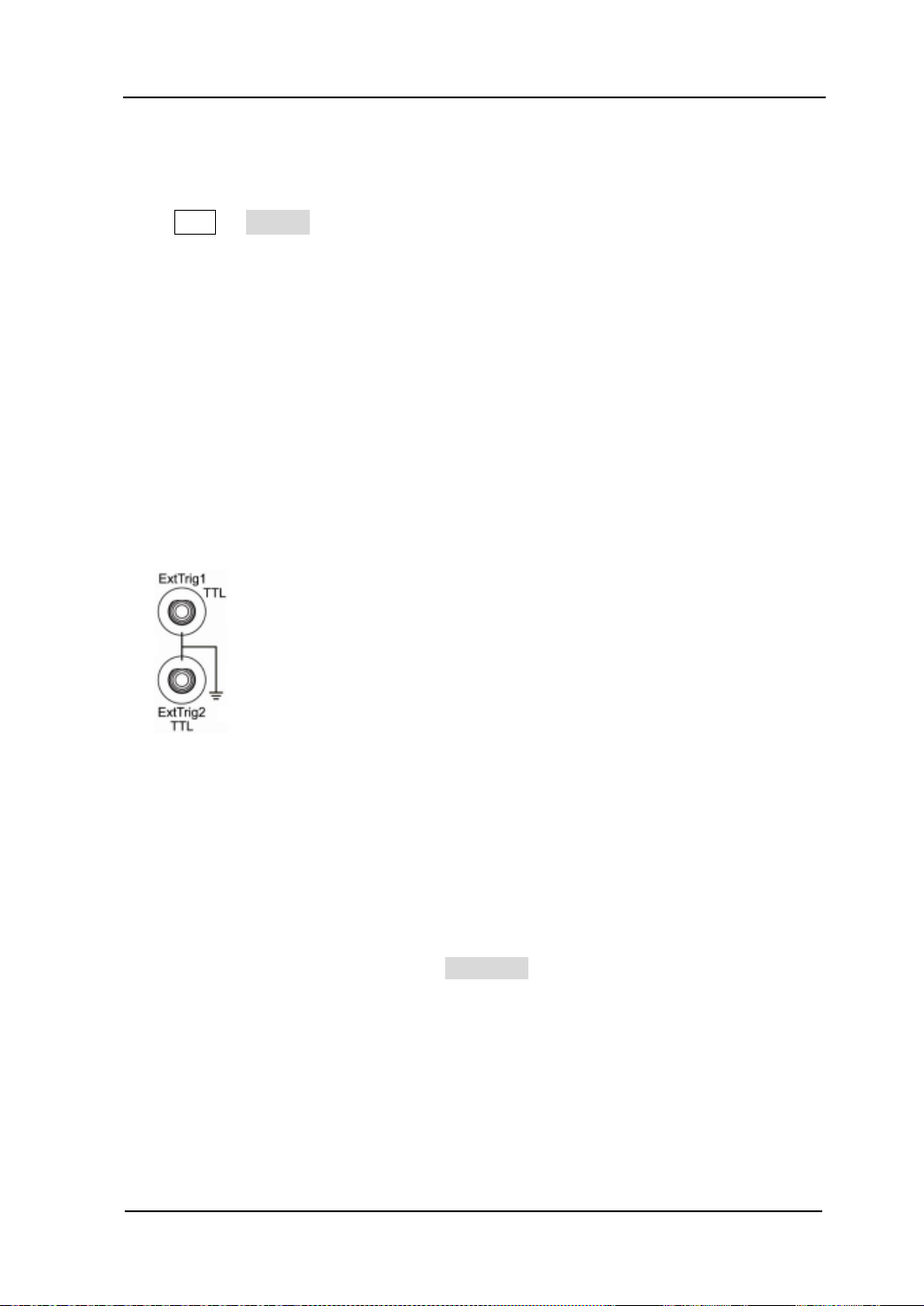
Chapter 4 Common Modulation Output RIGOL
To Select Modul ating Wavefor m Source
Press Mod Source to select “Int” or “Ext” modulating waveform source.
1. Inter nal Source
When internal s ource is selected, the modulatin g wav eform is set as a Square wi th
50% duty cyc le, and the “shift” frequency at which the output frequency shifts
between “carrier frequency” and “modulation frequency” is determined by “FSK
Rate”.
2. External Source
When external source is selected, the generator accepts the external modulating
signal from the [ExtTrig] connector (as shown in the picture bellow) at the rear
panel.
Notice that, the [ExtTrig] connector used to control FSK modulation externally is
different from the [ModIn] connector used to control AM/FM/PM modulation
externally. In FSK modulation, [ExtTrig] has an adjustable edge polarity.
To Set FSK Rate
When internal s ource is selected, press FSK Rate to set the “shift” frequency at which
the output frequency shifts between “carrier f re quency” and “hop frequency”.
Input the desired rate value using numeric keyboard or knob.
The available rate ranges from 2 mHz to 1 MHz, and the default value is 100 Hz.
Notice that, this menu will be grayed out and disabled when “external” source is
selected.
User’s Guide for DG5000
4-15
Page 94

RIGOL Chapter 4 Common Modulation Output
To Set Hop Frequency
The maximum alternating frequency (“hop” frequency) depends on the current
selected carrier waveform. Press HopFreq to highlight it, input the desire frequency
value using numeric keyboard or knob.
Sine: 1 μHz to 250 MHz
Square: 1 μHz to 120 MHz
Ramp: 1 μHz to 5 MHz
Arbitrary wav e fo rm: 1 μHz to 50 MHz
To Set Modula ting Polarity
Press Polarity to select the “Positive” or “Negative” of the modulating waveform to
control the output frequency.
When internal modulation is selected, if the polarity is “positive”, logic low of the
modulating waveform amplitude corresponds to carrier frequency output and logic
high corresponds to hop frequency output; if the polarity is “negative”, the situation is
the opposite.
When external modulation is selected, if the polarity is “positive”, logic low of the input
corresponds to carrier frequency output and logic high corresponds to hop frequency
output; if the polarity is “negative”, the situation is the opposite.
4-16
User’s Guide for DG5000
Page 95

Chapter 4 Common Modulation Output RIGOL
Phase Shift Keying (PSK)
When PSK (Phase Shift keying) modulation is selected, you can configure the
generator to make its output phase “shift” between two preset phase values (“carrier
phase” and “modulating phase”). The “shift” frequency (PSK Rate) is determined by
the signal level inside the instrument or from the rea r panel [ExtTrig] connector at the
rear panel.
To Select PSK Modulation
Press Mod Type PSK to enable PSK fun ction.
When Mod is enabled, Sweep or Burst will be automatically disabled (if
enabled currently).
After PSK is enabled, the instrument will generate PSK waveform with the
currently specified carrier and modulating waveform.
To Select Carrier Waveform Shape
PSK carrier waveform shape could be Sine, Square, Ramp or arbitrary waveform, and
the default is Sine.
Press the front panel key Sine, Square, Ramp or (Arb Select Wform) to
select desired carrier waveform shape.
Pulse (basic waveform), Noise and DC could not be as carrier waveform.
To Set Carrier Phase
After carrier waveform shape is selected, press Start Phase to highlight it, use
numeric keyboa rd or knob to input the desired phase. The available phase ranges
from 0 º to 360 º, the default value is 0 º.
To Select Modul ating Wavefor m Source
Press Mod Source to select “Int” or “Ext” modulating waveform source.
User’s Guide for DG5000
4-17
Page 96

RIGOL Chapter 4 Common Modulation Output
1. Inter nal Source
When internal s ource is selected, the modulating wav eform is s et as a Square wi th
50% duty cycle, and the “shift” frequency at which the output phase shifts
between “carrier phase ” and “modulating phase” is determined by “PSK Rate”.
2. External Source
When external source is selected, the generator accepts the external modulating
signal from the [ExtTrig] connector (see the following figure) at the rear panel.
Notice that, the [ExtTrig] connector used to control PSK modulation externally is
different from the [ModIn] connector used to control AM/FM/PM modulation
externally. In PSK modulation, [ExtTrig] has an adjustable edge polarity.
To Set PSK Rate
When internal source is selected, press PSK Rate to set the “shift” frequency at
which the output frequency shifts between “carrier phase” and “modulating phase”.
Input the desired rate value using numeric keyboard or knob.
The available rate ranges from 2 mHz to 1 MHz, and the default value is 100 Hz.
Notice that, this menu will be grayed out and disabled when external source is
selected.
To Set Modula ting Phase
Press Phase to set the modulating phase.
Input the desired phase value using numeric keyboard or knob.
The available phase ranges from 0 º to 360 º, and the default value is 180 º.
4-18
User’s Guide for DG5000
Page 97

Chapter 4 Common Modulation Output RIGOL
To Set Modula ting Polarity
Press Polarity to select the “Positive” or “Negative” of the modulating waveform to
control the output phase.
When internal modulation is selected, if the polarity is “positive”, logic low of the
modulating waveform amplitude corresponds to carrier phase output and logic high
corresponds to modulating phase output; if the polarity is “negative”, the situation is
the opposite.
When external modulation is selected, if the polarity is “positive”, logic low of the input
corresponds to carrier phase output and logic high corresponds to modulating phase
output; if the polarity is “negative”, the situation is the opposite.
User’s Guide for DG5000
4-19
Page 98
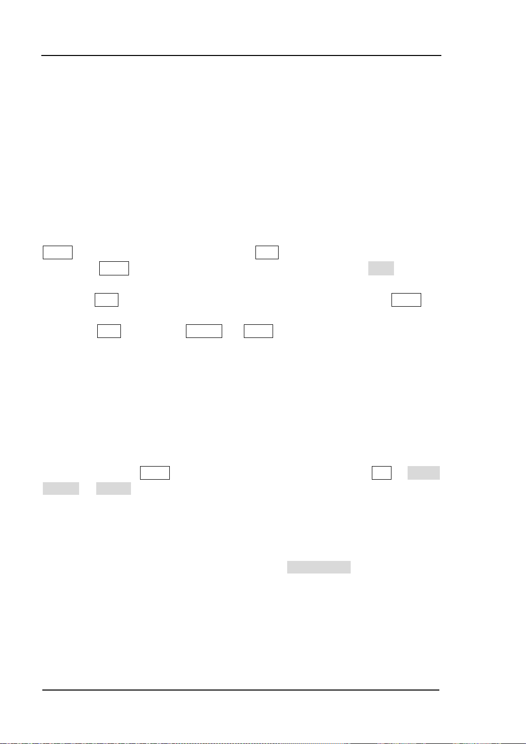
RIGOL Chapter 4 Common Modulation Output
Pulse Width Modulation (PWM)
A PWM (Pulse Width Modulation) modulated waveform consists of carrier waveform
and modulating waveform. The pulse width of the carrier waveform varies with the
instantaneous voltage of the modulating waveform.
To Select PWM Modulation
PWM can only be used to mod u late Pulse. To select PWM modulation type, press the
Pulse at the front panel first and then press Mod to enable PWM function.
If the Pulse function key has not been selected, PWM in Type menu is
unavailable.
When Mod is enabled but the modulation type is not PWM, pressing Pulse will
select PWM automatically.
When Mod is enabled, Sweep or Burst will be automatically disabled (if
enabled currently).
After PWM is enabled, the instrument will generate PWM waveform with the
currently specified carrier and modulating waveform.
To Select Pulse Waveform
As mentioned before, PWM can only be used to modulate Pulse. To select Pulse
waveform, press the Pulse at the front panel. Notice that, the pulse in Arb Select
Wform Builtin could not be used as carrier wav e form.
To Set Pulse Wi dth/Duty Cycle
After the carri er waveform shape is selected, press Width/Duty to highlight “Pulse
Width” or “Duty Cycle” and input the desired value using numeric keyboard or knob.
Pulse Width and Duty Cycle are correlative. For details, please refer to “
Width/Dut y Cycle” on page 2-7.
4-20
User’s Guide for DG5000
Pulse
Page 99

Chapter 4 Common Modulation Output RIGOL
-6 V
0 V
+6 V
To Select Modul ating Wavefor m Source
Press Mod Source to select “Int” or “Ext” modulating waveform source.
1. Inter nal Source
When internal modulation source is selected, press Shape to select Sine, Square,
Triangle, UpRamp , DnRa m p, N oise or A rb as m odulat ing w av efo rm. The defaul t is
Sine.
Square: Duty Cycle is 50%.
Triangle: Symmetry is 50%.
UpRamp: Symmetry is 100%.
DnRamp: Symmetry is 0%.
Arb: When the current arbitrary waveform is selected as the modulating
waveform, the gen erator automatically limits the arbitrary waveform length
as 2 kpts through samp ling.
Notice that, Noise could be used as modulating waveform but not carrier
waveform.
2. External Source
When external modulat ion s ou rce is selected, the Shape menu will be grayed out
and disabled. The generator accepts the external modulating signal from the [Mod
In] connector at the rear panel (as shown in the picture bellow). The “Width
Deviation” (or “Duty Cycle Deviation”) is controlled by the ±6 V signal level of the
connector.
User’s Guide for DG5000
4-21
Page 100

RIGOL Chapter 4 Common Modulation Output
To Set Modulating Wave form Frequency
When internal mo dulation source is selected, press PWM Freq to set the frequency of
the modulating waveform.
Input the desire frequency value using numeric keyboard or knob.
The available frequency ranges from 2 mHz to 50 kHz, and the default value is
100Hz.
Notice that, this menu will be grayed out and disabled when external source is
selected.
To Set Pulse Wi dth/Duty Cycle Deviation
Press WidthDeV (or “DutyDev”), input the desired value using numeric keyboard or
knob.
Width Deviation represents the variation in width (in seconds) in the modulated
waveform from the width of the original pulse waveform.
Pulse width range: 0 s to 500 ks.
Width deviation cannot exceed the current pulse width.
Width deviation is limited by the minimum pulse width and current edge time
setting.
Duty Cycle Deviation represents the variation in duty cycle (in %) of the
modulated waveform from the duty cycle of the original pulse waveform.
Duty cycle deviation range: 0% to 50%.
Duty cycle deviation cannot exceed the cur rent duty cycle deviation.
Duty cycle deviation is limited by the minimum duty cycle and curr ent edg e time
setting.
When external source is selected, width deviation (or duty cycle deviation) is
controlled by the ±6 V signal level of the [Mod In] connector at the rear panel. For
example, if the width deviation is set as 10s, +6 V signa l level corr esponds t o 10 s
width change.
4-22
User’s Guide for DG5000
 Loading...