

Page 1

RIGOL
User’s Guide
DG4000 Series Function/Arbitrary
Waveform Generator
Sept. 2011
RIGOL Technologies, Inc.
Page 2

Page 3

RIGOL
I
Guaranty and Declaration
Copyright
© 2011 RIGOL Technologies, Inc. All Rights Reserved.
Trademark Information
RIGOL is a registered trademark of RIGOL Technologies, Inc.
Publication Number
UGB04102-1110
Notices
RIGOL products are protected by patent law in and outside of P.R.C.
RIGOL reserves the right to modify or change parts of or all the
specifications and pricing policies at company’s sole decision.
Information in this publication replaces all previously corresponding material.
RIGOL shall not be liable for losses caused by either incidental or
consequential in connection with the furnishing, use or performance of this
manual as well as any information contained.
Any part of this document is forbidden to be copied or photocopied or
rearranged without prior written approval of RIGOL.
Product Certification
RIGOL guarantees this product conforms to the national and industrial standards
in China. International standard conformance certification is in progress, e.g. ISO.
Contact Us
If you have any problem or requirement when using our products, please contact
RIGOL or your local distributors, or visit: www.rigol.com
DG4000 Series User’s Guide
Page 4

RIGOL
II
Safety Requirement
General Safety Summary
Please review the following safety precautions carefully before putting the
instrument into operation so as to avoid any personal injuries or damages to the
instrument and any product connected to it. To prevent potential hazards, please
use the instrument only specified by this manual.
Use Proper Power Cord.
Only the power cord designed for the instrument and authorized by local country
could be used.
Ground The Instrument.
The instrument is grounded through the Protective Earth lead of the power cord.
To avoid electric shock, it is essential to connect the earth terminal of power cord
to the Protective Earth terminal before any inputs or outputs.
Observe All Terminal Ratings.
To avoid fire or shock hazard, observe all ratings and markers on the instrument
and check your manual for more information about ratings before connecting.
Use Proper Overvoltage Protection.
Make sure that no overvoltage (such as that caused by a thunderstorm) can reach
the product, or else the operator might expose to danger of electrical shock.
Change The Power Fuse.
If the power fuse needs to be changed, please return the instrument back to our
factory and the RIGOL authorized operator will change it for you.
Do Not Operate Without Covers.
Do not operate the instrument with covers or panels removed.
Avoid Circuit or Wire Exposure.
Do not touch exposed junctions and components when the unit is powered.
DG4000 Series User’s Guide
Page 5

RIGOL
III
Do Not Operate With Suspected Failures.
If you suspect damage occurs to the instrument, have it inspected by qualified
service personnel before further operations. Any maintenance, adjustment or
replacement especially to circuits or accessories must be performed by RIGOL
authorized personnel.
Keep Well Ventilation.
Inadequate ventilation may cause increasing of temperature or damages to the
device. So please keep well ventilated and inspect the intake and fan regularly.
Do Not Operate In Wet Conditions.
In order to avoid short circuiting to the interior of the device or electric shock,
please do not operate in a humid environment.
Do Not Operate in an Explosive Atmosphere.
In order to avoid damages to the device or personal injuries, it is important to
operate the device away from an explosive atmosphere.
Keep Product Surfaces Clean and Dry.
To avoid the influence of dust and/or moisture in air, please keep the surface of
device clean and dry.
Electrostatic Prevention.
Operate in an electrostatic discharge protective area environment to avoid
damages induced by static discharges. Always ground both the internal and
external conductors of the cable to release static before connecting.
Handling Safety
Please handle with care during transportation to avoid damages to buttons, knob
interfaces and other parts on the panels.
DG4000 Series User’s Guide
Page 6
RIGOL
IV
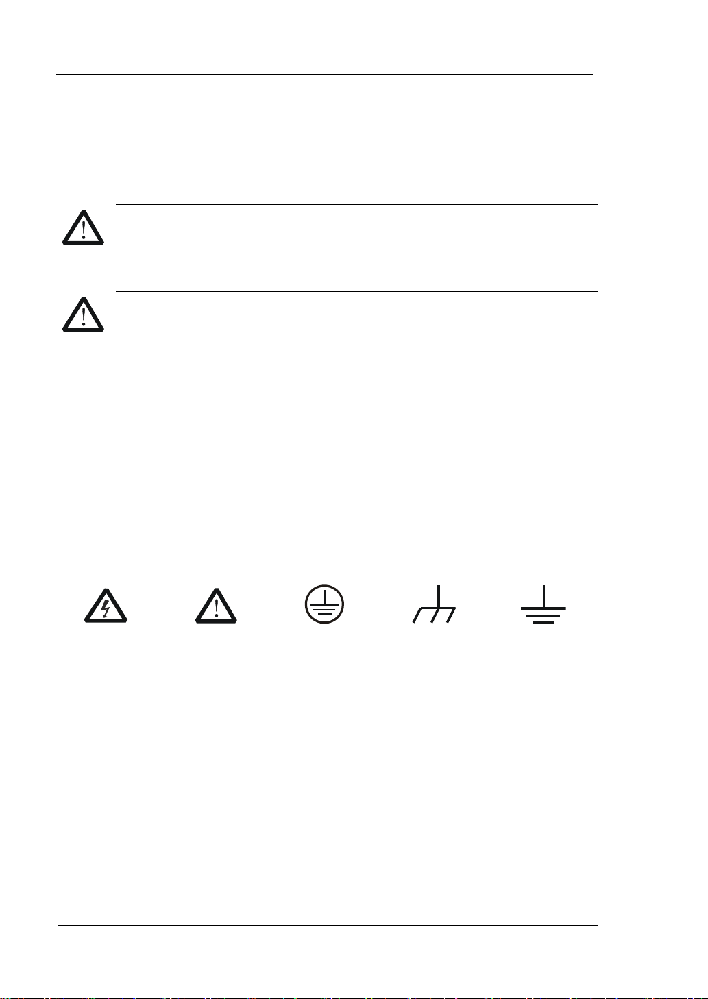
WARNING
Warning statements indicate the conditions or practices that could result in
injures or loss of life.
CAUTION
Caution statements indicate the conditions or practices that could result in
damage to this product or other property.
Hazardous
Voltage
Refer to
Instructions
Protective
Earth
Terminal
Chassis
Ground
Test
Ground
Safety Terms and Symbols
Terms in this Manual. These terms may appear in this manual:
Terms on the Product. These terms may appear on the product:
DANGER indicates an injury or hazard may immediately happen.
WARNING indicates an injury or hazard may be accessible potentially.
CAUTION indicates a potential damage to the instrument or other property
might occur.
Symbols on the Product. These symbols may appear on the product:
DG4000 Series User’s Guide
Page 7
RIGOL
V
CAUTION
To avoid damages to the instrument, do not expose them to corrosive
liquids.
WARNING
To avoid injury resulting from short circuit, make sure the instrument is
completely dry before reconnecting it to power source.
General Care and Cleaning
General Care
Do not leave or store the instrument exposed to direct sunlight for long periods of
time.
Cleaning
Clean the instrument regularly according to its operating conditions. To clean the
exterior surface, perform the following steps:
1. Disconnect the instrument from all power sources.
2. Clean the loose dust on the outside of the instrument with a lint- free cloth
(with a mild detergent or water). When clean the LCD, take care to avoid
scarifying it.
DG4000 Series User’s Guide
Page 8

RIGOL
VI
Environmental Considerations
The following symbol indicates that this product complies with the applicable
European Union requirements according to Directives 2002/96/EC on waste electrical
and electronic equipment (WEEE) and batteries.
Product End-of-Life Handling
The equipment may contain substances that could be harmful to the environment
or human health. In order to avoid releasing such substances into the environment
and harming human health, we encourage you to recycle this product in an
appropriate system that will ensure that most of the materials are reused or
recycled appropriately. Please contact your local authorities for disposal or
recycling information.
DG4000 Series User’s Guide
Page 9

RIGOL
VII
DG4000 Series Overview
DG4000 is a dual-channel economical, high-performance and multifunctional
generator that combines many functions in one, including Function Generator,
Arbitrary Waveform Generator, Pulse Generator, Harmonics Generator,
Analog/Digital modulator and Counter.
Main Features:
Adopt the Direct Digital Synthesizer (DDS) technology and provide stable,
precise, pure and low distortion signals.
7 inches, 16M true color TFT LCD, displaying parameters and graphics of the
two channels at the same time.
160MHz, 100MHz or 60MHz maximum output frequency (for Sine), 500MSa/s
sample rate, 14bits vertical resolution.
Precisely adjust the phases of the two channels.
150 waveforms or functions: Sine, Square, Ramp, Pulse, Noise, Sinc,
Exponential Rise, Exponential Fall, ECG, Gauss, Haversine, Lorentz, Dual
Tones, Harmonics, Video Signal, Radar Signal, DC etc.
Enable to edit 16kpts arbitrary waveform and support step-by-step output of
arbitrary waveform.
Rise Time and Fall Time of the Pulse could be adjusted separately.
Enable to output harmonic with specified order and amplitude, enable to
output up to 16th order of harmonic.
Support to superpose Gauss Noise onto basic waveforms.
Various modulation types: AM, FM, PM, ASK, FSK, PSK, BPSK, QPSK, 3FSK,
4FSK, OSK and PWM modulations.
Support frequency sweep and Burst output.
Dual channels can perform internal/external modulation and
internal/external/manual trigger separately or at the same time.
Dual channels can output sync signal separately or at the same time.
Support to enable Frequency Coupling, Phase Coupling and Amplitude
Coupling separately or at the same time.
Provide counter function; enable to measure various parameters of external
signal such as frequency, period, duty cycle, positive pulse width and negative
pulse width; provide statistic function of measurement results.
Support waveform copy and state copy between channels.
Enable to store and recall 10 arbitrary waveform data files and 10 instrument
DG4000 Series User’s Guide
Page 10

RIGOL
VIII
state files as well as recall Csv and Txt files stored in USB storage device.
Plenty of standard interfaces: USB Host, USB Device and LAN
Abundant I/O: waveform output, sync signal output, modulation input, 10MHz
clock input/output, trigger input/output.
Support USB storage device using FAT file system.
Support remote control through 10/100M Ethernet web.
Conform to LXI-C instrument standards (Version 1.2).
Provide Chinese and English built-in help and input methods.
Provide powerful waveform editing PC software.
Provide security lock hole.
DG4000 Series User’s Guide
Page 11

RIGOL
IX
Document Overview
Subjects in this Manual:
Chapter 1 Quick Start
This chapter introduces the front/rear panel, user interface and parameter setting
method, as well as announcements during first use of the instrument.
Chapter 2 Basic Waveform Output
This chapter introduces how to output basic waveforms, e.g. Sine and Square.
Chapter 3 Arbitrary Waveform Output
This chapter introduces how to output built-in or user-defined waveforms.
Chapter 4 Harmonics Output
This chapter introduces how to output harmonics with specified order.
Chapter 5 Modulated Waveform Output
This chapter introduces how to output modulated waveforms, e.g. AM, FSK and
PWM.
Chapter 6 Sweep
This chapter introduces how to generate a frequency Sweep.
Chapter 7 Burst
This chapter introduces how to generate a Burst waveform.
Chapter 8 Counter
This chapter introduces how to use the counter.
Chapter 9 Store and Recall
This chapter introduces how to store and recall the waveform data or the
instrument state settings.
Chapter 10 Utility and System Settings
This chapter introduces some utility functions and setting methods of system
parameters.
Chapter 11 Remote Control
This chapter introduces how to control the instrument remotely.
Chapter 12 Troubleshooting
This chapter lists commonly encountered failures that may appear during the use
of the generator and their solutions.
DG4000 Series User’s Guide
Page 12

RIGOL
X
Model
Channels
Max. Frequency
Sample Rate
DG4062
2
60MHz
500MSa/s
DG4102
2
100MHz
500MSa/s
DG4162
2
160MHz
500MSa/s
Chapter 13 Specifications
This chapter lists the performances and general specifications of the instrument.
Chapter 14 Appendix
This chapter provides the information about the options and accessories, as well as
other points for attention.
Format Conventions in this Manual:
1. Buttons:
The function key at the front panel is denoted by the format of “Text Box +
Button Name (Bold)” in the manual, for example, Sine.
2. Menu Softkey:
The menu softkey is denoted by the format of “Character Shading + Menu Word
(Bold)” in the manual, for example, Freq.
3. Connector
The connector at the front or rear panel is denoted by the format of
“Brackets+Connector Name (Bold)” in the manual, for example, [Sync].
4. Operation Steps:
The next step of the operation is denoted by an arrow “” in the manual. For
example, Sine Freq represents pressing the function key Sine at the front
panel and then pressing the menu softkey Freq.
Content Conventions in this Manual:
DG4000 series cover the following models. This manual takes DG4162 as an
example.
DG4000 Series User’s Guide
Page 13

RIGOL
XI
Contents
Guaranty and Declaration ......................................................................... I
Safety Requirement ................................................................................ II
General Safety Summary ........................................................................... II
Safety Terms and Symbols ....................................................................... IV
General Care and Cleaning ........................................................................ V
Environmental Considerations ............................................................ VI
DG4000 Series Overview....................................................................... VII
Document Overview ............................................................................... IX
Chapter 1 Quick Start ......................................................................... 1-1
General Inspection ................................................................................ 1-2
To Adjust the Supporting Legs ................................................................ 1-3
Dimensions ........................................................................................... 1-4
Front Panel ........................................................................................... 1-6
Rear Panel ........................................................................................... 1-13
To Connect to Power ............................................................................. 1-16
User Interface ...................................................................................... 1-17
Parameter Setting Method ..................................................................... 1-20
Numeric Keyboard.......................................................................... 1-20
Direction keys and Knob ................................................................. 1-21
To Use the Built-In Help ........................................................................ 1-22
To Use the Security Lock ....................................................................... 1-23
To Use the Rack Mount Kit .................................................................... 1-24
Kit Parts List .................................................................................. 1-24
Installation Tool ............................................................................. 1-25
Installation Space .......................................................................... 1-26
Installation Procedure .................................................................... 1-28
Chapter 2 Basic Waveform Output ..................................................... 2-1
To Select Output Channel ....................................................................... 2-2
To Select Basic Waveform....................................................................... 2-3
To Set Frequency .................................................................................. 2-4
To Set Amplitude ................................................................................... 2-5
DG4000 Series User’s Guide
Page 14

RIGOL
XII
To Set DC Offset Voltage ......................................................................... 2-7
To Set Start Phase .................................................................................. 2-8
Align Phase ........................................................................................... 2-9
To Set Duty Cycle ................................................................................. 2-11
To Set Symmetry .................................................................................. 2-12
To Set Parameters for Pulse .................................................................. 2-13
Pulse Width/Duty Cycle .................................................................. 2-13
Leading/Trailing Edge Time ............................................................. 2-14
Delay ........................................................................................... 2-15
Recover Delay ............................................................................... 2-15
To Enable Output ................................................................................. 2-17
Basic Waveform Output Example ........................................................... 2-18
Chapter 3 Arbitrary Waveform Output ............................................... 3-1
To Enable Arbitrary Waveform ................................................................. 3-2
Step-By-Step Output Mode ...................................................................... 3-3
To Select Arbitrary Waveform .................................................................. 3-4
Built-In Waveform ............................................................................ 3-4
Stored Waveform ............................................................................. 3-9
Volatile Waveform ............................................................................ 3-9
To Create New Arbitrary Waveform ........................................................ 3-10
Example: Edit Points ...................................................................... 3-13
Example: Edit Block ....................................................................... 3-15
To Edit Arbitrary Waveform ................................................................... 3-17
Chapter 4 Harmonic Output ............................................................... 4-1
Overview ............................................................................................... 4-2
To Set Fundamental Waveform Parameters ............................................... 4-2
To Set Harmonic Order ........................................................................... 4-3
To Select Harmonic Type ......................................................................... 4-3
To Set Harmonic Amplitude ..................................................................... 4-4
To Set Harmonic Phase ........................................................................... 4-4
Chapter 5 Modulated Waveform Output ............................................ 5-1
AM ....................................................................................................... 5-2
To Select AM Modulation .................................................................. 5-2
To Select Carrier Waveform Shape ..................................................... 5-2
To Set Carrier Frequency .................................................................. 5-2
To Select Modulating Waveform Source .............................................. 5-3
DG4000 Series User’s Guide
Page 15

RIGOL
XIII
To Set Modulating Waveform Frequency ............................................ 5-4
To Set Modulation Depth ................................................................. 5-4
FM ....................................................................................................... 5-5
To Select FM Modulation .................................................................. 5-5
To Select Carrier Waveform Shape .................................................... 5-5
To Set Carrier Frequency ................................................................. 5-5
To Select Modulating Waveform Source ............................................. 5-6
To Set Modulating Waveform Frequency ............................................ 5-7
To Set Frequency Deviation .............................................................. 5-7
PM ....................................................................................................... 5-8
To Select PM Modulation .................................................................. 5-8
To Select Carrier Waveform Shape .................................................... 5-8
To Set Carrier Frequency ................................................................. 5-8
To Select Modulating Waveform Source ............................................. 5-9
To Set Modulating Waveform Frequency ........................................... 5-10
To Set Phase Deviation ................................................................... 5-10
ASK..................................................................................................... 5-11
To Select ASK Modulation ............................................................... 5-11
To Select Carrier Waveform Shape ................................................... 5-11
To Set Carrier Amplitude ................................................................. 5-11
To Select Modulating Waveform Source ............................................ 5-12
To Set ASK Rate ............................................................................. 5-12
To Set Modulating Amplitude ........................................................... 5-13
To Set Modulating Polarity .............................................................. 5-13
FSK ..................................................................................................... 5-14
To Select FSK Modulation ................................................................ 5-14
To Select Carrier Waveform Shape ................................................... 5-14
To Set Carrier Frequency ................................................................ 5-14
To Select Modulating Waveform Source ............................................ 5-15
To Set FSK Rate ............................................................................. 5-16
To Set Hop Frequency .................................................................... 5-16
To Set Modulating Polarity .............................................................. 5-16
PSK ..................................................................................................... 5-17
To Select PSK Modulation ................................................................ 5-17
To Select Carrier Waveform Shape ................................................... 5-17
To Set Carrier Phase ....................................................................... 5-17
To Select Modulating Waveform Source ............................................ 5-18
DG4000 Series User’s Guide
Page 16

RIGOL
XIV
To Set PSK Rate ............................................................................ 5-18
To Set PSK Phase........................................................................... 5-19
To Set Modulating Polarity .............................................................. 5-19
BPSK .................................................................................................. 5-20
To Select BPSK Modulation ............................................................. 5-20
To Select Carrier Waveform Shape ................................................... 5-20
To Set Carrier Phase ...................................................................... 5-20
To Select Modulating Waveform Source ............................................ 5-21
To Set BPSK Rate ........................................................................... 5-21
To Set BPSK Phase ......................................................................... 5-22
QPSK .................................................................................................. 5-23
To Select QPSK Modulation ............................................................. 5-23
To Select Carrier Waveform Shape ................................................... 5-23
To Set Carrier Phase ...................................................................... 5-23
To Select Modulating Waveform Source ............................................ 5-24
To Set QPSK Rate .......................................................................... 5-24
To Set QPSK Phases ....................................................................... 5-24
3FSK ................................................................................................... 5-25
To Select 3FSK Modulation .............................................................. 5-25
To Select Carrier Waveform Shape ................................................... 5-25
To Set Carrier Frequency ................................................................ 5-25
Modulation Source ......................................................................... 5-26
To Set 3FSK Rate ........................................................................... 5-26
To Set Hop Frequencies .................................................................. 5-26
4FSK ................................................................................................... 5-27
To Select 4FSK Modulation .............................................................. 5-27
To Select Carrier Waveform Shape ................................................... 5-27
To Set Carrier Frequency ................................................................ 5-27
Modulation Source ......................................................................... 5-28
To Set 4FSK Rate ........................................................................... 5-28
To Set Hop Frequencies .................................................................. 5-28
OSK .................................................................................................... 5-29
To Select OSK Modulation ............................................................... 5-29
To Select Carrier Waveform Shape ................................................... 5-30
To Set Carrier Frequency ................................................................ 5-30
To Select Modulating Waveform Source ............................................ 5-30
To Set OSK Rate ............................................................................ 5-31
DG4000 Series User’s Guide
Page 17

RIGOL
XV
To Set Oscillate Period .................................................................... 5-31
PWM ................................................................................................... 5-32
To Select PWM Modulation .............................................................. 5-32
To Select Carrier Waveform Shape ................................................... 5-32
To Set Pulse Width/Duty Cycle ........................................................ 5-32
To Select Modulating Waveform Source ............................................ 5-33
To Set Modulating Waveform Frequency ........................................... 5-33
To Set Pulse Width/Duty Cycle Deviation .......................................... 5-34
Chapter 6 Sweep ................................................................................ 6-1
To Enable Frequency Sweep ................................................................... 6-2
Start Frequency and End Frequency ........................................................ 6-2
Center Frequency and Frequency Span .................................................... 6-3
Sweep Type .......................................................................................... 6-4
Linear Sweep.................................................................................. 6-4
Log Sweep ..................................................................................... 6-5
Step Sweep .................................................................................... 6-6
Sweep Time .......................................................................................... 6-7
Return Time .......................................................................................... 6-8
Mark Frequency .................................................................................... 6-8
Start Hold ............................................................................................. 6-9
End Hold ............................................................................................. 6-10
Sweep Trigger Source ........................................................................... 6-10
Trigger Output Edge ............................................................................. 6-11
Chapter 7 Burst .................................................................................. 7-1
To Enable Burst Mode ............................................................................ 7-2
Burst Type ............................................................................................ 7-2
N Cycle Burst .................................................................................. 7-2
Infinite Burst .................................................................................. 7-3
Gated Burst .................................................................................... 7-4
Burst Phase .......................................................................................... 7-6
Burst Period .......................................................................................... 7-6
Gated Polarity ....................................................................................... 7-6
Burst Delay ........................................................................................... 7-7
Burst Trigger Source .............................................................................. 7-7
Trigger Output Edge .............................................................................. 7-8
Chapter 8 Counter .............................................................................. 8-1
DG4000 Series User’s Guide
Page 18

RIGOL
XVI
To Enable the Counter ............................................................................ 8-2
To Set the Counter ................................................................................. 8-3
Statistic ................................................................................................. 8-5
Chapter 9 Store and Recall ................................................................ 9-1
Storage System Overview ....................................................................... 9-2
To Select File Type ................................................................................. 9-4
To Select Browser Type ........................................................................... 9-5
File Operation ........................................................................................ 9-6
Save ............................................................................................... 9-6
Recall ............................................................................................. 9-8
Copy .............................................................................................. 9-9
Paste .............................................................................................. 9-9
Delete ............................................................................................ 9-9
New Directory ............................................................................... 9-10
Chapter 10 Utility and System Settings ....................................... 10-1
Overview ............................................................................................. 10-2
Channel Setting ................................................................................... 10-3
Sync ............................................................................................. 10-3
Sync Polarity ................................................................................. 10-4
Output Polarity .............................................................................. 10-5
Resistance Setting ......................................................................... 10-5
Noise Setting ................................................................................. 10-6
Noise Scale ................................................................................... 10-6
To Configure the Remote Interface ........................................................ 10-7
LAN Setting ................................................................................... 10-7
To Set USB Device Type ............................................................... 10-11
System Setting ................................................................................... 10-12
Number Format ........................................................................... 10-12
Language ................................................................................... 10-13
Power On Setting......................................................................... 10-13
Power Setting .............................................................................. 10-13
Brightness .................................................................................. 10-14
Beeper ....................................................................................... 10-14
Screen Saver ............................................................................... 10-14
Clock Source ............................................................................... 10-14
System Information ..................................................................... 10-16
DG4000 Series User’s Guide
Page 19

RIGOL
XVII
Print .................................................................................................. 10-17
Channel Coupling ............................................................................... 10-18
Channel Copy..................................................................................... 10-21
User-defined Waveform Key ................................................................ 10-22
Restore Default .................................................................................. 10-24
Chapter 11 Remote Control .......................................................... 11-1
Remote Control Overview ...................................................................... 11-2
Remote Control Mode ........................................................................... 11-3
User-defined Programming ............................................................. 11-3
To Use PC Software ........................................................................ 11-7
Chapter 12 Troubleshooting ......................................................... 12-1
Chapter 13 Specifications ............................................................. 13-1
Chapter 14 Appendix .................................................................... 14-1
Appendix A: Options and Accessories ..................................................... 14-1
Appendix B: Warranty ........................................................................... 14-2
Appendix C: Any Comment or Question? ................................................. 14-3
Index ....................................................................................................... 1
DG4000 Series User’s Guide
Page 20

Page 21

Chapter 1 Quick Start RIGOL
1-1
Chapter 1 Quick Start
This chapter introduces the front/rear panel, user interface and parameter setting
method, as well as announcements during first use of the instrument.
Subjects in this chapter:
General Inspection
To Adjust the Supporting Legs
Dimensions
Front Panel
Rear Panel
To Connect to Power
User Interface
Parameter Setting Method
To Use the Built-In Help
To Use the Security Lock
To Use the Rack Mount Kit
DG4000 Series User’s Guide
Page 22

RIGOL Chapter 1 Quick Start
1-2
General Inspection
1. Inspect the shipping container for damage.
If there are damages in the container or foam, keep them until the whole
machine and the accessories pass the electrical and mechanical tests.
If your instrument has damaged during shipping, please contact your shipper
and carrier for compensation. RIGOL will provide no free repair or
replacement.
2. Inspect the instrument.
In case of any mechanical damage or defect, or if the instrument does not
operate properly or pass the electrical and mechanical tests, contact your local
sales representative of RIGOL.
3. Check the Accessories
If the contents are incomplete or damaged, please contact your local sales
representative of RIGOL.
DG4000 Series User’s Guide
Page 23
Chapter 1 Quick Start RIGOL
1-3
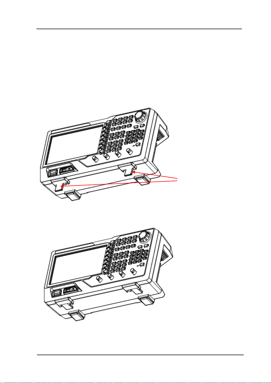
Supporting Legs
To Adjust the Supporting Legs
DG4000 allows users to unfold the supporting legs as stands to tilt the generator
upwards for easier operation and observation during operation (as shown in Figure
1-1). Users can fold the supporting legs for easier storage or carry when the
instrument is not in use (as shown in Figure 1-2).
Figure 1-1 Unfold the Supporting Legs
Figure 1-2 Fold the Supporting Legs
DG4000 Series User’s Guide
Page 24
RIGOL Chapter 1 Quick Start
1-4
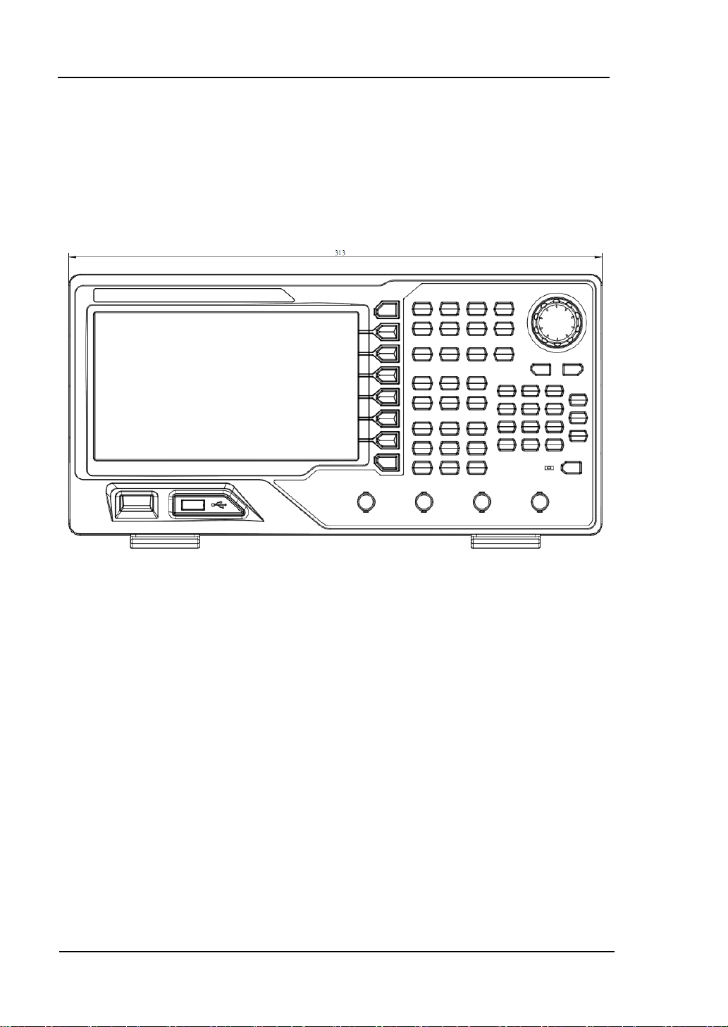
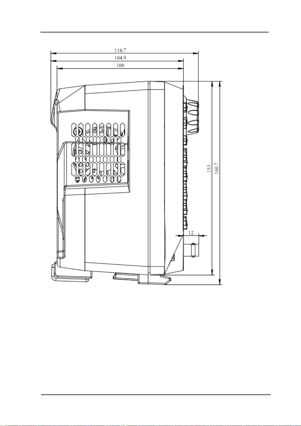
Dimensions
The appearance and dimensions of DG4000 are as shown in Figure 1-3 and Figure
1-4 and the unit is mm.
Figure 1-3 Front View
DG4000 Series User’s Guide
Page 25
Chapter 1 Quick Start RIGOL
1-5
Figure 1-4 Side View
DG4000 Series User’s Guide
Page 26
RIGOL Chapter 1 Quick Start
1-6
1. Power Key
2. USB Host
3. Menu Softkey
4. Page Up/Down
5. CH1 Output
6. CH1 Sync Output
7. CH2 Output
8. CH2 Sync Output
10. Counter
11. Numeric
Keyboard
9. Channels Control
12. Knob
13. Direction
Keys
14. Waveforms
15. Modes
16. Return
17. Shortcuts/Utility
18. LCD
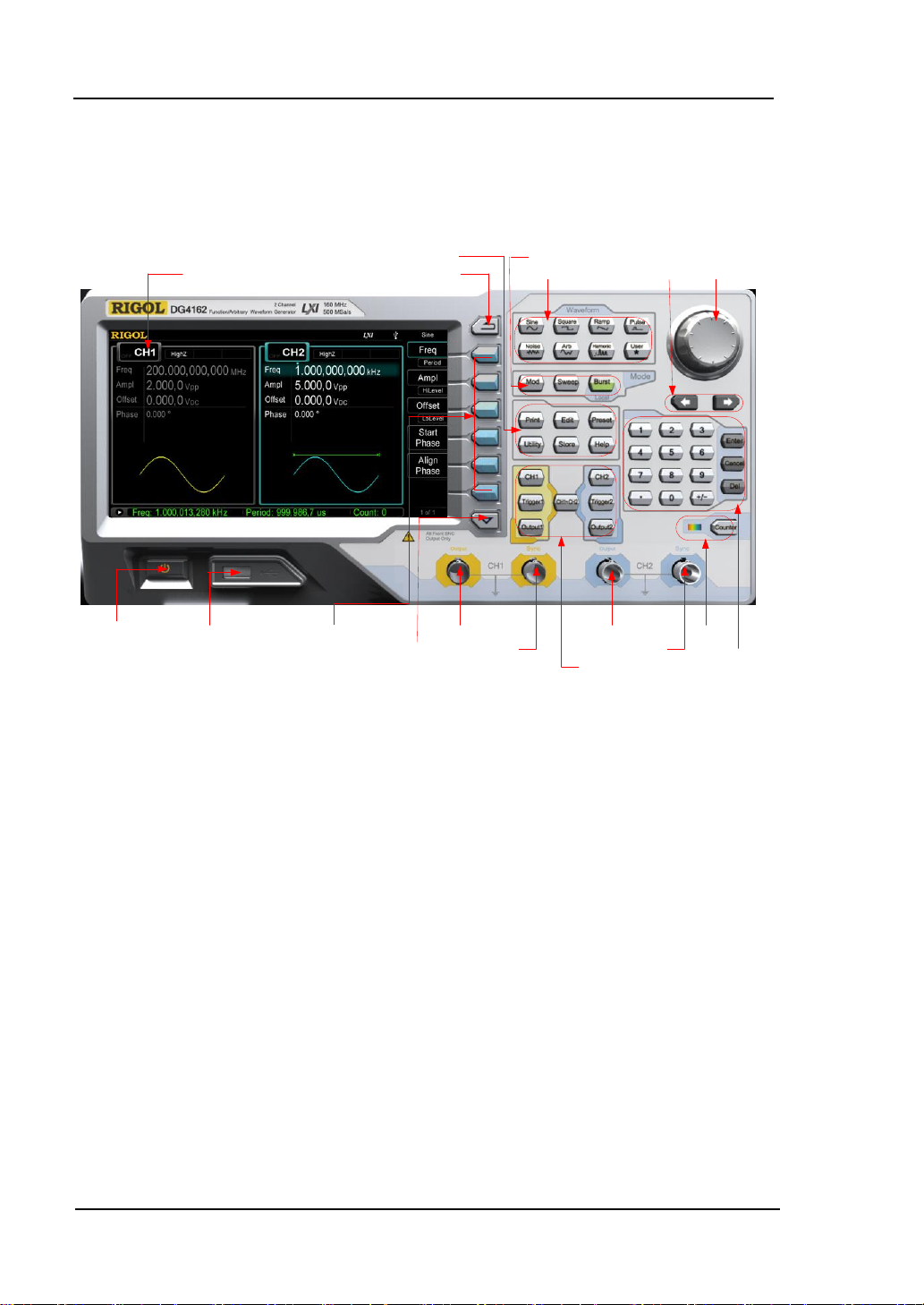
Front Panel
The front panel of DG4000 is shown below.
Figure 1-5 DG4000 Front Panel
1. Power Key
The power softkey is used to turn the generator on or off. When the power
softkey is turned off, the generator is in standby mode and the generator is in
power-off mode only when the power cable at the rear panel is pulled out.
Users can enable or disable the function of this softkey. When enabled, users
need to press this softkey to start the instrument after power-on; when
disabled, the instrument starts automatically after power-on.
2. USB Host
Support FAT file format USB storage device. Read the waveform or state files
from the USB storage device, or store the current instrument state and edited
waveform data into the USB storage device, or store the content currently
displayed on the screen in specified picture format (.bmp) in USB storage
device.
DG4000 Series User’s Guide
Page 27

Chapter 1 Quick Start RIGOL
1-7
3. Menu Softkey
Correspond to the left menus respectively. Press any softkey to activate the
corresponding menu.
4. Page Up/Down
Open the previous or next page of the current function menu.
5. CH1 Output
BNC connector with 50Ω nominal output impedance.
When Output1 is enabled (the backlight turns on), this connector output
waveform according to the current configuration of CH1.
6. CH1 Sync Output
BNC connector with 50Ωnominal output impedance.
When the sync output of CH1 is enabled, this connector outputs the sync
signal corresponding to the current settings of CH1 (refer to the introduction in
Sync).
7. CH2 Output
BNC connector with 50Ωnominal output impedance.
When Output2 is enabled (the backlight turns on), this connector output
waveform according to the current configuration of CH2.
8. CH2 Sync Output
BNC connector with 50Ωnominal output impedance.
When the sync output of CH2 is enabled, this connector outputs the sync
signal corresponding to the current settings of CH2 (refer to the introduction in
Sync).
9. Channels Control
CH1: used to select CH1. When CH1 is selected (the backlight turns on), users
can set the waveform and parameters of CH1.
CH2: used to select CH2. When CH2 is selected (the backlight turns on), users
can set the waveform and parameters of CH2.
Trigger1: in sweep or burst mode, it is used to trigger CH1 to generate a
DG4000 Series User’s Guide
Page 28
RIGOL Chapter 1 Quick Start
1-8
sweep or burst output manually (only when Output1 is enabled).
Trigger2: in sweep or burst mode, it is used to trigger CH2 to generate a
sweep or burst output manually (only when Output2 is enabled).
Output1: enable or disable the output of CH1.
Output2: enable or disable the output of CH2.
CH1 CH2: execute channel copy (refer to the introductions in Channel
Copy).
10. Counter
Press Counter to turn the counter on or off. When the counter is turned on,
the backlight of the key is illuminated and the left indicator flickers. If the
counter interface is currently displayed, press this key again to disable counter
function; if the screen currently displays interfaces other than the counter
interface, press this key again to switch to counter interface (refer to the
introductions in Counter).
11. Numeric Keyboard
It is used to input parameters and consists of numbers (0 to 9), decimal point
(.), operators (+/-) and buttons (“Enter”, “Cancel” and “Del”). If a negative is
required, please input an operator “-” before the numbers. In addition, the
decimal point “.” can be used to switch units quickly and the operators “+/-”
can be used to switch between uppercase and lowercase (for the use method
of the numeric keyboard, refer to the introduction in Parameter Setting
Method).
12. Knob
During parameter setting, it is used to increase (clockwise) or decrease
(counterclockwise) the current highlighted number.
It is used to select file storage location or select the file to be recalled when
storing or recalling file.
It is used to switch the character in the soft keyboard when entering filename.
It is used to select built-in waveform when defining the shortcut waveform of
User.
DG4000 Series User’s Guide
Page 29

Chapter 1 Quick Start RIGOL
1-9
13. Direction Keys
When using the knob and direction keys to set parameters, the direction keys
are used to switch the digits of the number.
During filename input, they are used to move the cursor.
14. Waveforms
Sine----Sine
Generate a Sine waveform with frequency from 1μHz to 160MHz.
When the function is enabled, the backlight of the button turns on.
Enable to change Frequency/Period, Amplitude/High Level, Offset/Low
Level and Start Phase of the Sine waveform.
Square----Square
Generate a Square waveform with frequency from 1μHz to 50MHz and variable
duty cycle.
When the function is enabled, the backlight of the button turns on.
Enable to change Frequency/Period, Amplitude/High Level, Offset/Low
Level, Duty Cycle and Start Phase of the Square waveform.
Ramp----Ramp
Generate a Ramp waveform with frequency from 1μHz to 4MHz and variable
symmetry.
When the function is enabled, the backlight of the button turns on.
Enable to change Frequency/Period, Amplitude/High Level, Offset/Low
Level, Symmetry and Start Phase of the Ramp waveform.
Pulse----Pulse
Generate a Pulse waveform with frequency from 1μHz to 40MHz and variable
pulse width and edge time.
When the function is enabled, the backlight of the button turns on.
Enable to change Frequency/Period, Amplitude/High Level, Offset/Low
Level, Pulse Width/Duty Cycle, Leading Edge Time, Trailing Edge Time and
Delay of the Pulse waveform.
Noise----Noise
Generate a Gauss Noise with 120MHz bandwidth.
When the function is enabled, the backlight of the button turns on.
DG4000 Series User’s Guide
Page 30

RIGOL Chapter 1 Quick Start
1-10
Enable to change Amplitude/High Level and Offset/Low Level of the
Noise.
Arb----Arbitrary Waveforms
Generate an arbitrary waveform with frequency from 1μHz to 40MHz.
Provide Step-by-Step output mode.
Generate 150 built-in waveforms: DC, Sinc, Exponential Rise, Exponential
Fall, ECG, Gauss, Haversine, Lorentz, Pulse, Dual-Tone etc.; output
arbitrary waveforms stored in USB storage device.
Generate arbitrary waveforms (16 kpts) edited from the front panel or
through PC software and then downloaded to the instrument by the users.
When the function is enabled, the backlight of the button turns on.
Enable to change Frequency/Period, Amplitude/High Level, Offset/Low
Level and Start Phase of the arbitrary waveform.
Harmonic——Harmonic
Generate harmonics with frequency from 1μHz to 80MHz.
Output up to 16
th
order of harmonic.
Users can set the harmonic “Order”, “Type”, “Ampl” and “Phase”.
User----User-defined Waveform Key
Users can define the built-in waveform frequently used as shortcut (Utility
UserKey). And then, in any operation interface, press User to quickly open
the desired waveform and set its parameters.
15. Modes
Mod----Modulation
Generate the modulated waveforms. Provide various analog modulation and
digital modulation modes and can generate AM, FM, PM, ASK, FSK, PSK, BPSK,
QPSK, 3FSK, 4FSK, OSK or PWM modulated signal.
Support internal and external modulations.
Sweep----Sweep
Generate the frequency sweeping signal of Sine, Square, Ramp and Arbitrary
Waveforms (except DC).
Support three sweep types: Linear, Log and Step.
Support three trigger sources: Internal, External and Manual.
DG4000 Series User’s Guide
Page 31

Chapter 1 Quick Start RIGOL
1-11
Provide the “Mark” function.
When the function is enabled, the backlight of the button turns on.
Burst----Burst
Generate burst waveforms of Sine, Square, Ramp, Pulse and Arbitrary
waveform (except DC).
Support three burst types: N Cycle, Infinite and Gated.
Noise can also be used to generate Gated burst.
Support three trigger sources: Internal, External and Manual.
When the function is enabled, the backlight of the button turns on.
Note: when the instrument is working in remote mode, you can return it back
to local mode by pressing Burst.
16. Return
This key is used to return to the previous menu.
17. Shortcuts/Utility
Print: used to execute print function. Save the content shown on the screen
as image in USB storage device.
Edit: this key is the shortcut of “Arb Edit Wform” and is used to enter the
ArbEdit interface quickly.
Preset: used to return the instrument state to default or user-defined states
(refer to the introduction in Restore Default).
Utility: used to set the system parameters. When this function is enabled, the
backlight of the button turns on.
Store: store or recall the instrument state or user-defined arbitrary data.
Support normal file operations.
Provide a built-in non-volatile memory (C Disk) and an external USB
storage device (D Disk).
When the function is enabled, the backlight of the button turns on.
Help: to get context help information about any front-panel key or menu
softkey, press this key until it is illuminated and then press the desired key.
DG4000 Series User’s Guide
Page 32

RIGOL Chapter 1 Quick Start
1-12
CAUTION
Overvoltage protection of the output channel will take effect once any of
the following conditions is met.
Amplitude setting in the generator is greater than 4 Vpp; the input
voltage is greater than ± 11.25 V (± 0.1 V) and frequency is lower than
10kHz.
Amplitude setting in the generator is lower than or equal to 4 Vpp; the
input voltage is greater than ± 4.5 V (± 0.1 V) and frequency is lower
than 10kHz.
The message “OverLoad protect, The output is off!” will appear on the
screen when overvoltage protection takes effect.
18. LCD
800 × 480 TFT color LCD is used to display the current function menu and
parameters setting, system state as well as prompt messages.
DG4000 Series User’s Guide
Page 33

Chapter 1 Quick Start RIGOL
1-13
8. 7. 6. 5. 4. 3. 2. 1.
Rear Panel
The rear panel of DG4000 is as shown in the figure below.
Figure 1-6 DG4000 Rear Panel
1. AC Power Input
This generator can accept AC power supply of 100-240V, 45-440Hz.
Power Fuse: 250V, T2 A.
2. LAN
Connect the generator to the local area network for remote control through
this interface. This generator conforms to LXI-C instrument standards and can
quickly build test system with other devices to easily realize system
integration.
3. Security Lock Hole
Users can use the security lock (buy it by themselves) to lock the instrument
at a fixed location.
DG4000 Series User’s Guide
Page 34

RIGOL Chapter 1 Quick Start
1-14
4. USB Device
PC can be connected through this interface to control the generator remotely
through PC software.
5. 10MHz In/Out
BNC female connector with 50Ω nominal impedance. The function of this
connector is determined by the type of clock used by the generator. DG4000
can use internal or external clock (refer to the introduction in Clock Source ).
When internal clock source is used, the connector (used as 10MHz Out)
can output 10MHz clock signal generated by the internal crystal oscillator
of the generator.
When external clock source is used, the connector (used as 10MHz In)
accepts a 10MHz external clock signal.
This connector is usually used to synchronize multiple instruments (refer
to the introduction in Sync).
6. CH1: Mod/FSK/Trig
BNC female connector with 50Ω nominal impedance. Its function is
determined by the current working mode of CH1.
Mod:
If AM, FM, PM, PWM or OSK is enabled for CH1 and external modulation
source is used, this connector accepts an external modulation signal.
FSK:
If ASK, FSK or PSK is enabled for CH1 and external modulation source is
used, this connector accepts an external modulation signal (users can set
the polarity of the signal).
Trig In:
If CH1 is in sweep or burst mode and external trigger source is used, this
connector accepts an external trigger signal (users can set the polarity of
the signal).
Trig Out:
If CH1 is in sweep or burst mode and internal or manual trigger source is
used, this connector outputs a trigger signal with specified edge.
7. CH2: Mod/FSK/Trig
BNC female connector with 50Ω nominal impedance. Its function is
determined by the current working mode of CH2.
DG4000 Series User’s Guide
Page 35

Chapter 1 Quick Start RIGOL
1-15
Mod:
If AM, FM, PM, PWM or OSK is enabled for CH2 and external modulation
source is used, this connector accepts an external modulation signal.
FSK:
If ASK, FSK or PSK is enabled for CH2 and external modulation source is
used, this connector accepts an external modulation signal (users can set
the polarity of the signal).
Trig In:
If CH2 is in sweep or burst mode and external trigger source is used, this
connector accepts an external trigger signal (users can set the polarity of
the signal).
Trig Out:
If CH2 is in sweep or burst mode and internal or manual trigger source is
used, this connector outputs a trigger signal with specified edge.
8. External Signal Input (Counter)
BNC female connector with 50Ω nominal impedance. It is used to accept an
external signal to be measured by the counter.
DG4000 Series User’s Guide
Page 36

RIGOL Chapter 1 Quick Start
1-16
CAUTION
If the power fuse needs to be changed, please return the instrument back
to our factory and the RIGOL authorized operator will change it for you.
To Connect to Power
DG4000 accepts AC power supply: 100 to 240V, 45Hz to 440Hz. Please use the
power cable provided in the accessories to connect the instrument to AC power (as
shown in Figure 1-7). At this point, the generator is powered on and the power
button at the lower-left corner of the front panel is in breathing state.
Figure 1-7 To Connect to Power
DG4000 Series User’s Guide
Page 37

Chapter 1 Quick Start RIGOL
1-17
2. Status Bar
1. Current
Function
12. Menu Page Number
3. Channel State4. Channel Configuration
5. Frequency
6. Amplitude
7. Offset
8. Phase
9. Waveform
10. Counter
11. Menu
When the instrument is connected into LAN successfully, this indicator
will light.
When the generator works in remote mode, this indicator will light.
When the generator detects connected USB storage device, this
indicator will light.
User Interface
DG4000 user interface displays the parameters and waveforms of the two
channels at the same time. The figure below is the interface when both CH1 and
CH2 select Sine. Different contents will be displayed when different functions are
enabled.
Figure 1-8 User Interface
1. Current Function
Display the name of the function currently selected. For example, “Sine”
indicates that “Sine” waveform function is currently selected and “ArbEdit”
indicates that “Arbitrary Waveform Edit” function is currently selected.
2. Status Bar
The following indicators would be displayed according to the current
configuration.
DG4000 Series User’s Guide
Page 38

RIGOL Chapter 1 Quick Start
1-18
3. Channel Status
Display areas of CH1 and CH2. Indicate whether the channel is selected and
turned on (ON/OFF).The area of the channel currently selected is highlighted
and the on/off state of the channel currently turned on is “ON”.
Note:
When a channel is “Selected”, it does not mean that the channel is turned on.
When CH1 is selected, users can configure the parameters of CH1 and the
backlight of CH1 turns on. When CH1 is turned on, CH1 can output waveform
according to the current configuration and the backlight of Output1 turns on.
4. Channel Configurations
Display the current output configuration in each channel, including output
resistance, mode and type of modulating source or trigger source.
Output Resistance
High Impedance: display “HighZ”
Load: display the resistance value, the default is “50Ω”
Mode
Modulation: display “Mod”
Sweep: display “Sweep”
Burst: display “Burst”
Modulating/Trigger Source Type
Internal modulating/trigger: display “Internal”
External modulating/trigger: display “External”
Manual Trigger: display “Manual”
5. Frequency
Display the current waveform frequency in each channel. Press the
corresponding softkey Freq and use the numeric keyboard or direction keys
and knob to modify this parameter. The parameter that can be modified
currently will be highlighted and the lightspot above the number indicates
current cursor location.
6. Amplitude
Display the current waveform amplitude in each channel. Press the
corresponding softkey Ampl and use the numeric keyboard or direction keys
and knob to modify this parameter. The parameter that can be modified
DG4000 Series User’s Guide
Page 39

Chapter 1 Quick Start RIGOL
1-19
currently will be highlighted and the lightspot above the number indicates
current cursor location.
7. Offset
Display the current waveform DC offset in each channel. Press the
corresponding softkey Offset and use the numeric keyboard or direction keys
and knob to modify this parameter. The parameter that can be modified
currently will be highlighted and the lightspot above the number indicates
current cursor location.
8. Phase
Display the current waveform phase in each channel. Press the corresponding
softkey Start Phase and use the numeric keyboard or direction keys and knob
to modify this parameter. The parameter that can be modified currently will be
highlighted and the lightspot above the number indicates current cursor
location.
9. Waveform
Display the currently selected waveform shape in each channel.
10. Counter
Only available when the counter is turned on and can display the current
measurement state of the counter briefly or in detail.
Brief: only display frequency, period and the number of measurements
performed.
Detail: display the configurations of the counter, five measurement values
(Frequency, Period, Duty Cycle, Positive Pulse Width and Negative Pulse
Width) and the number of measurements performed.
11. Menu
Display the operation menu corresponding to the function currently selected.
For example, the “Sine” function menu is displayed in the above figure.
12. Menu Page Number
Display the total number of pages and the current page number of the menu,
such as “1 of 1” or “1 of 2”.
DG4000 Series User’s Guide
Page 40

RIGOL Chapter 1 Quick Start
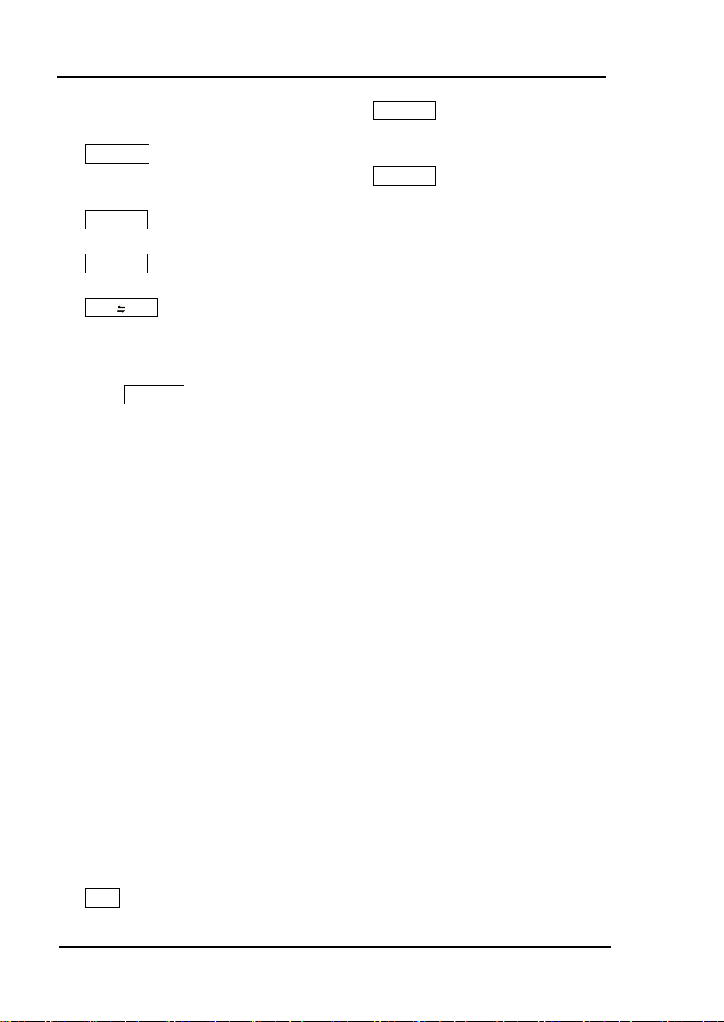
1-20
The numeric keyboard consists of:
Number Keys
The 0 to 9 number keys are used to
directly input the desired parameter
value.
Parameter Setting Method
Users can use the numeric keyboard or knob and direction keys to set parameters.
Numeric Keyboard
Decimal Point
Press this key to insert a decimal point “.” at the current position of the cursor.
Operator Key
The operator key “+/-” is used to modify the operator of the parameter. Press
this key to set the parameter operator to “-”; press this key again to switch the
operator to “+”. Note that the operator key is used to switch between
uppercase and lowercase in filename edit.
Enter Key
Press this key to finish parameter input and add the default unit for the
parameter.
Cancel Key
(1) During parameter input, press this key to clear the input in the active
function area and exit parameter input.
(2) Turn the display in the active function area off.
Del Key
(1) During parameter input, press this key to delete the character at the left
of the cursor.
(2) During filename edit, press this key to delete the characters input.
DG4000 Series User’s Guide
Page 41

Chapter 1 Quick Start RIGOL
1-21
Functions of the knob:
When the parameter is in editable state, turn the knob
to increase (clockwise) or reduce (counterclockwise)
the parameter with specified step.
Direction keys and Knob
Functions of the direction keys:
1. During parameter input, use the direction keys to move the cursor to select
the digit to be edited.
2. During filename edit, use the direction keys to move the cursor.
During filename edit, use the knob to select the characters in the soft
keyboard.
In Arb Select WformBuiltIn and Utility UserKey, use the knob to
select arbitrary waveform.
In store and recall, use the knob to select the storage location of the file or to
select the file to be recalled.
DG4000 Series User’s Guide
Page 42

RIGOL Chapter 1 Quick Start
1-22
To Use the Built-In Help
To get context help information about any front-panel key or menu softkey, press
Help to illuminate the key and then press the desired key to get corresponding
help.
Pressing Help twice will get the following common help.
1. View the last displayed message.
2. View error queue of the remote commands.
3. Get the help information of a key.
4. Generate a basic waveform.
5. Generate an arbitrary waveform.
6. Generate a modulated waveform.
7. Generate a frequency Sweep.
8. Generate a Burst waveform.
9. Storage management.
10. Synchronize multiple Generators.
11. Get technical support from RIGOL.
DG4000 Series User’s Guide
Page 43

Chapter 1 Quick Start RIGOL
1-23
Security Lock Hole
To Use the Security Lock
Use the security lock (option) to lock the generator at a fixed location. As shown in
the figure below, align the lock with the lock hole and plug it into the lock hole
vertically, turn the key clockwise to lock the instrument and then pull the key out.
Figure 1-9 Security Lock Hole
DG4000 Series User’s Guide
Page 44

RIGOL Chapter 1 Quick Start
1-24
No.
Name
Qty
Part No.
Description
1-1
Front Panel
1
RM-DG4-01
1-2
Support Board
1
RM-DG4-02
1-3
Left Plate
1
RM-DG4-03
1-4
Right Plate
1
RM-DG4-04
1-5
Pressure Feet
2
RM-DG4-05
1-6
Built-in Fitting
2
RM-DG4-06
2-1
M4 Screw
18
RM-SCREW-01
M4 x 6 Phil-Slot Pan Head Machine
Screw Nail
2-2
M6 Screw
4
RM-SCREW-02
M6 x 20 Phil-Slot Pan Head Machine
Screw Nail
2-3
M6 Screw
4
RM-SCREW-03
M6 x 4 Square Machine Female
Screw Contain Lock Blade
To Use the Rack Mount Kit
This instrument can be installed into a standard 19 inches cabinet.
Figure 1-10 Rack Mount Kit
Kit Parts List
The part list of the rack mount kit (as shown in Figure 1-10) of DG4000 is as shown
in the table below. Wherein, the “No.” column corresponds to Figure 1-11 and
Figure 1-12.
Table 1-1 Kit Parts List
DG4000 Series User’s Guide
Page 45

Chapter 1 Quick Start RIGOL
1-25
Figure 1-11 Parts of Rack Mount Kit
2-1 2-2 2-3
Figure 1-12 Screws and Nuts
Installation Tool
PH2 Phillips Screwdriver (recommended).
DG4000 Series User’s Guide
Page 46

RIGOL Chapter 1 Quick Start
1-26
Installation Space
The following requirements must be fulfilled by the machine cabinet in which the
instrument is mounted.
The machine cabinet must be a standard 19-inch one.
At least 4U (177.8 mm) space should be provided by the machine cabinet.
The depth inside the machine cabinet should not be less than 180 mm.
The dimension of the instrument after being installed is as shown below.
DG4000 Series User’s Guide
Page 47

Chapter 1 Quick Start RIGOL
1-27
DG4000 Series User’s Guide
Page 48

RIGOL Chapter 1 Quick Start
1-28
Installation Procedure
Only authorized operators can execute the installation operation. Improper
installation might result in damage of the instrument or incorrect installation of the
instrument on the rack.
1. Install the right and left plates: align the detents of the right and left plates
with the openings on the support board and insert them into the support
board respectively, then fix them with four M4 screws.
2. Install the front panel of the rack mount kit: fix the front panel onto the frame
installed in the previous step using six M4 screws.
DG4000 Series User’s Guide
Page 49

Chapter 1 Quick Start RIGOL
1-29
3. Fix the bottom of the instrument: fix the instrument onto the support board
using two pressure feet and four M4 screws.
4. Fix the top of the instrument: fix the top of the instrument using two built-in
fittings and four M4 screws.
DG4000 Series User’s Guide
Page 50

RIGOL Chapter 1 Quick Start
1-30
5. Load into the machine cabinet: mount the rack with the instrument fixed to it
into a standard 19-inch machine cabinet with four M6 screws and four M6
square nuts.
6. Post-installation notice: the rack occupies a height of 4U. The holes pointed
out by the arrows are installation holes. Note that they should be aligned with
during installation.
DG4000 Series User’s Guide
Page 51

Chapter 2 Basic Waveform Output RIGOL
2-1
Chapter 2 Basic Waveform Output
DG4000 can output basic waveforms (including Sine, Square, Ramp, Pulse and
Noise) from one of the channels separately or from the two channels at the same
time. At start-up, the instrument outputs a sine waveform with 1kHz frequency
and 5Vpp amplitude by default. This chapter introduces how to configure the
instrument to output various basic waveforms.
Subjects in this chapter:
To Select Output Channel
To Select Basic Waveform
To Set Frequency
To Set Amplitude
To Set DC Offset Voltage
To Set Start Phase
Align Phase
To Set Duty Cycle
To Set Symmetry
To Set Parameters for Pulse
To Enable Output
Basic Waveform Output Example
DG4000 Series User’s Guide
Page 52

RIGOL Chapter 2 Basic Waveform Output
2-2
To Select Output Channel
Users can configure DG4000 to output basic waveform from a single channel or
from dual channels at the same time. Please select the desired channel before
configuring waveform parameters. At start-up, CH1 is selected by default.
Press CH1 or CH2 at the front panel and the corresponding area in the user
interface is illuminated. At this point, users can configure the waveform and
parameters of the channel selected.
Note: CH1 and CH2 can not be selected at the same time. Users can first select
CH1 and then select CH2 after configuring the waveform and parameters of CH1.
DG4000 Series User’s Guide
Page 53

Chapter 2 Basic Waveform Output RIGOL
2-3
To Select Basic Waveform
DG4000 can output 5 kinds of basic waveforms including Sine, Square, Ramp,
Pulse and Noise. At start-up, Sine is selected by default.
1. Sine
Press Sine at the front panel to select sine waveform and the backlight of the
button turns on. At this point, “Sine” and the parameter setting menu of sine
waveform are displayed on the right of the user interface.
2. Square
Press Square at the front panel to select square waveform and the backlight
of the button turns on. At this point, “Square” and the parameter setting menu
of square waveform are displayed on the right of the user interface.
3. Ramp
Press Ramp at the front panel to select ramp waveform and the backlight of
the button turns on. At this point, “Ramp” and the parameter setting menu of
ramp waveform are displayed on the right of the user interface.
4. Pulse
Press Pulse at the front panel to select pulse and the backlight of the button
turns on. At this point, “Pulse” and the parameter setting menu of pulse are
displayed on the right of the user interface.
5. Noise
Press Noise at the front panel to select noise and the backlight of the button
turns on. At this point, “Noise” and the parameter setting menu of noise are
displayed on the right of the user interface.
DG4000 Series User’s Guide
Page 54

RIGOL Chapter 2 Basic Waveform Output
2-4
To Set Frequency
Frequency is one of the most important parameters of basic waveforms. For
different instrument models and different waveforms, the setting ranges of
frequency are different. For detailed information, please refer to “Frequency
Characteristics” in Specifications. The default frequency is 1kHz.
The frequency displayed on the screen is the default value or the frequency
previously set. When the instrument function is changed, if this frequency is valid
under the new function, the instrument will still use this frequency; otherwise, the
instrument would display prompt message and set the frequency to the frequency
upper limit of the new function automatically.
Press Freq/Period to highlight “Freq”. At this point, use the numeric keyboard or
direction keys and knob to input the frequency value. Then, select the desired unit
from the pop-up menu.
For the input method of frequency value, refer to the introduction in
Parameter Setting Method.
The frequency units available are MHz, kHz, Hz, mHz and μHz.
Press this softkey again to switch to period setting. At this point, “Period” is
highlighted.
The period units available are sec, msec, μsec and nsec.
DG4000 Series User’s Guide
Page 55

Chapter 2 Basic Waveform Output RIGOL
2-5
Unit Switch
Vpp is the unit for signal peak-peak value and Vrms is the unit for signal
effective value. The default unit is Vpp. Users can quickly switch the current
amplitude unit from the front panel.
For different waveforms, the relations between Vpp and Vrms are different.
The relation of the two units is as shown in the figure below (take sine
waveform as an example).
To Set Amplitude
The amplitude range is limited by the “Resistance” and “Freq/Period” settings.
Please refer to “Output Characteristics” in Specifications. The default value is
5Vpp.
The amplitude displayed on the screen is the default value or the amplitude
previously set. When the instrument configuration (such as frequency) is changed,
if this amplitude is valid, the instrument will still use this amplitude; otherwise, the
instrument would display prompt message and set the amplitude to the amplitude
upper limit of the new configuration automatically. Users can also use “High Level”
or “Low Level” to set the amplitude.
Press Ampl/HiLevel to highlight “Ampl”, and then use the numeric keyboard or
direction keys and knob to input the amplitude value. Then, select the desired unit
from the pop-up menu.
For the input method of amplitude value, refer to the introduction in
Parameter Setting Method.
The amplitude units available are Vpp, mVpp, Vrms, mVrms and dBm (valid in
HighZ).
Press this softkey again to switch to high level setting. At this point, “HiLevel”
is highlighted.
The high level units available are V and mV.
DG4000 Series User’s Guide
Page 56

RIGOL Chapter 2 Basic Waveform Output
2-6
Vpp=2Vamp
Vrms=0.707Vamp
Vamp
According to the figure above, the conversion relation between Vpp and
Vrms fulfills the following equation:
Vrms22Vpp
For example, to convert 2Vpp to the corresponding value in Vrms,
press · in the numeric keyboard and select Vrms menu. For sine
waveform, the converted value is 707.2mVrms.
DG4000 Series User’s Guide
Page 57

Chapter 2 Basic Waveform Output RIGOL
2-7
To Set DC Offset Voltage
The offset range is limited by the “Resistance” and “Ampl/HiLevel” settings.
Please refer to the “Output Characteristics” in Specifications. The default value is
0VDC.
The DC offset voltage displayed on the screen is the default value or the offset
previously set. When the instrument configuration (such as resistance) is changed,
if this offset is valid, the instrument will still use this offset; otherwise, the
instrument would display prompt message and set the offset to the offset upper
limit of the new configuration automatically.
Press Offset/LoLevel to highlight “Offset”, and then use the numeric keyboard or
direction keys and knob to input the offset value. Then, select the desired unit
from the pop-up menu.
For the input method of offset value, refer to the introduction in Parameter
Setting Method.
The DC offset voltage units available are V
Press this softkey again to switch to low level setting. At this point, “LoLevel”
is highlighted.
The low level units available are V and mV.
and mVDC.
DC
DG4000 Series User’s Guide
Page 58

RIGOL Chapter 2 Basic Waveform Output
2-8
To Set Start Phase
The setting range of start phase is from 0° to 360° and the default is 0°.
The start phase displayed on the screen is the default value or the phase
previously set. When the instrument function is changed, the new function will still
use this phase.
Press Start Phase to highlight the softkey, and then use the numeric keyboard or
direction keys and knob to input the start phase value. Then, select the unit “°”
from the pop-up menu. For the input method of phase value, refer to the
introduction in Parameter Setting Method.
DG4000 Series User’s Guide
Page 59

Chapter 2 Basic Waveform Output RIGOL
2-9
CH1
CH2
CH1
CH2
Align Phase
DG4000 series dual-channel generators enable to align the phases of the two
channels. Pressing down this softkey will re-configure the two channels, and
enable the generator to output with specified frequency and start phase.
For two signals whose frequencies are the same or in multiple, this operation will
align their phases. For example, assume a sine waveform (1kHz, 5Vpp, 0 °) is
output from CH1, while another (1kHz, 5Vpp, 180°) from CH2. Use an oscilloscope
to sample and display the two signals, and then toggle the channel output switch
of the generator, you will see that the waveforms shown on the oscilloscope do not
always have a phase deviation of 180°. At this point, press Align Phase on the
generator and the waveforms shown on the oscilloscope will have a phase
deviation of 180° without any adjustment of the start phase of the generator.
Figure 2-1 Before Aligning Phase
Figure 2-2 After Aligning Phase
DG4000 Series User’s Guide
Page 60

RIGOL Chapter 2 Basic Waveform Output
2-10
Note: the Align Phase menu is grayed out and disabled when one of the two
channels is in modulation mode.
DG4000 Series User’s Guide
Page 61

Chapter 2 Basic Waveform Output RIGOL
2-11
T
t
Duty Cycle=t/T*100%
To Set Duty Cycle
Duty Cycle is defined as the percentage that the high level takes up in the whole
period as shown in the figure below. This parameter is only available when square
waveform is selected.
The duty cycle range is limited by the “Freq/Period” setting. Please refer to
“Signal Characteristics” in Specifications. The default value is 50%.
Press Duty Cycle to highlight the softkey, and then use the numeric keyboard or
direction keys and knob to input the duty cycle value. Then, select the unit “%”
from the pop-up menu. For the input method of duty cycle value, refer to the
introduction in Parameter Setting Method.
DG4000 Series User’s Guide
Page 62

RIGOL Chapter 2 Basic Waveform Output
2-12
T
t
Symmetry=t/T*100%
To Set Symmetry
Symmetry is defined as the percentage that the rising period takes up in the whole
period as shown in the figure below. This parameter is only available when ramp is
selected.
The setting range of symmetry is from 0% to 100% and the default is 50%.
Press Symmetry to highlight the softkey, and then use the numeric keyboard or
direction keys and knob to input the symmetry value. Then, select the unit “%”
from the pop-up menu. For the input method of symmetry value, refer to the
introduction in Parameter Setting Method.
DG4000 Series User’s Guide
Page 63

Chapter 2 Basic Waveform Output RIGOL
2-13
脉宽
10%
t
Rise
t
Fall
90%
50%
Pulse Period
Pulse Width
To Set Parameters for Pulse
To output a pulse, users need to set the “Pulse Width/Duty Cycle”, “Leading edge”,
“Trailing edge”, “Delay” and “Recover Delay” in addition to the basic parameters
(such as frequency, amplitude, DC offset voltage, start phase, high level, low level
and align phase) introduced above.
Pulse Width/Duty Cycle
Pulse Width is defined as the time from the 50% threshold of a rising edge
amplitude to the 50% threshold of the next falling edge amplitude as shown in the
figure above.
Pulse Width range is limited by the “Minimum Pulse Width” and the “Pulse
Period” (for the ranges of “Minumum Pulse Width” and “Pulse Period”, please
refer to “Signal Characteristics” in Specifications). The default value is 500μs.
Pulse Width ≥ Minimum Pulse Width
Pulse Width ≤ Pulse Period - Minimum Pulse Width × 2
Pulse Duty Cycle is defined as the percentage that the Pulse Width takes up in the
whole period.
DG4000 Series User’s Guide
Page 64

RIGOL Chapter 2 Basic Waveform Output
2-14
Pulse Width and Duty Cycle are correlative. Once a parameter is changed, the
other will be automatically changed. Pulse Duty Cycle is limited by the “Minimum
Pulse Width” and the “Pulse Period”.
Pulse Duty Cycle ≥ 100 × Minimum Pulse Width ÷ Pulse Period
Pulse Duty Cycle ≤ 100 × (1 - 2 × Minimum Pulse Width ÷ Pulse Period)
Press Width/Duty to highlight “Width”, and use the numeric keyboard or
direction keys and knob to input the desired value. Then, select the desired unit
from the pop-up menu.
For the input method of the value, refer to the introduction in Parameter
Setting Method.
Selectable Pulse Width units: sec, msec, μsec, nsec.
Press this softkey again to switch to duty cycle setting (at this point, it is set to
20% automatically).
Leading/Trailing Edge Time
The Leading (rising) edge time is defined as the duration of the pulse amplitude
rising from 10% to 90% threshold, while the Trailing (falling) edge time is defined
as the duration of the pulse amplitude moving down from 90% to 10% threshold
as shown in the figure above.
The range of leading/trailing edge time is limited by the currently specified pulse
width limit as shown in the formula below. DG4000 will automatically adjust the
edge time to match the specified pulse width if the value currently set exceeds the
limit value.
Leading/Trailing Edge Time ≤ 0.625 × Pulse Width
Press Leading (or Trailing) to highlight the softkey. Use the numeric keyboard or
direction keys and knob to input the desired value and select the desired unit from
the pop-up menu.
For the input method of the value, refer to the introduction in Parameter
Setting Method.
Selectable Leading/Trailing Edge Time units: sec, msec, μsec, nsec.
Leading edge time and trailing edge time are independent from each other
and users can set them separately.
DG4000 Series User’s Guide
Page 65

Chapter 2 Basic Waveform Output RIGOL
2-15
Delay
CH1 Output
CH2 Output
Delay
Delay is defined as the delayed time of the output of a channel relative to the
output of the other channel. The range of delay is from 0s to pulse period and the
default is 0s.
Press Delay to highlight the softkey. Use the numeric keyboard or direction keys
and knob to input the desired value and select the desired unit from the pop-up
menu.
For the input method of the value, refer to the introduction in Parameter
Setting Method.
Selectable Delay Time units: sec, msec, μsec, nsec.
Recover Delay
Press Pulse, then use to open the 2/2 menu page and press Restore, the
generator will align the delay between the two channels. Assume that CH1 and CH2
output pulse waveforms with the same parameters. Use the oscilloscope to sample
the waveforms of the two channels and display them stably. Then, toggle the output
switch of the generator. The two waveforms displayed on the oscilloscope have a
certain delay. At this point, press Restore on the generator and the waveforms will
be displayed on the oscilloscope without any delay.
DG4000 Series User’s Guide
Page 66

RIGOL Chapter 2 Basic Waveform Output
2-16
CH1
CH2
CH1
CH2
Figure 2-3 Before Restore
Figure 2-4 After Restore
Note that Restore is grayed out and disabled if any of the two channels is in
modulation mode.
DG4000 Series User’s Guide
Page 67

Chapter 2 Basic Waveform Output RIGOL
2-17
To Enable Output
After configuring the parameters of the waveform selected, waveform output
could be enabled.
Note: before enabling waveform output, you can also configure parameters (such
as Resistance and Polarity) related to the channel output through “CH1/CH2Set”
menu in Utility. For details, please refer to the introduction in Channel Setting.
Press Output1 or/and Output2 at the front panel and the backlight of the button
turns on. The instrument outputs the configured waveform from the [Output1]
or/and [Output2] connector at the front panel.
DG4000 Series User’s Guide
Page 68

RIGOL Chapter 2 Basic Waveform Output
2-18
Basic Waveform Output Example
Configure the generator to output a pulse waveform with 1.5MHz frequency,
500mVpp amplitude, 5mV
edge time, 100ns trailing (falling) edge time and 5ns delay.
1. Press CH1 at the front panel and the backlight turns on, indicating that CH1 is
selected.
2. Press Pulse at the front panel and the backlight turns on, indicating that
Pulse waveform is selected.
3. Press Freq/Period to highlight “Freq”. The lightspot above the number
indicates current cursor location (as shown in the figure below). Use the
numeric keyboard or direction keys and knob to input the frequency value
“1.5” and select the unit “MHz” from the pop-up menu.
DC offset, 200ns pulse width, 75ns leading (rising)
DC
Figure 2-5 To Set Waveform Parameters
4. Press Ampl/HiLevel to highlight “Ampl”. The lightspot above the number
indicates current cursor location. Use the numeric keyboard or direction keys
and knob to input the amplitude value “500” and select the unit “mVpp” from
the pop-up menu.
DG4000 Series User’s Guide
Page 69

Chapter 2 Basic Waveform Output RIGOL
2-19
5. Press Offset/LoLevel to highlight “Offset”. The lightspot above the number
indicates current cursor location. Use the numeric keyboard or direction keys
and knob to input the offset value “5” and select the unit “mVDC” from the
pop-up menu.
6. Press Width/Duty to highlight “Width”. The lightspot above the number
indicates current cursor location. Use the numeric keyboard or direction keys
and knob to input “200” and select the unit “nsec” from the pop-up menu. At
this point, the pulse duty cycle changes accordingly.
7. Press Leading to highlight it. The lightspot above the number indicates
current cursor location. Use the numeric keyboard or direction keys and knob
to input “75” and select the unit “nsec” from the pop-up menu. Press Trailing
to highlight it. The lightspot above the number indicates current cursor
location. Use the numeric keyboard or direction keys and knob to input “100”
and select the unit “nsec” from the pop-up menu.
8. Press Delay to highlight it. The lightspot above the number indicates current
cursor location. Use the numeric keyboard or direction keys and knob to input
“5” and select the unit “nsec” from the pop-up menu.
9. Press Output1 at the front panel to turn CH1 output on. At this point, CH1
outputs waveform with the specified parameters. Connect the output terminal
of CH1 to the oscilloscope and the waveform is as shown in the figure below.
Figure 2-6 To Output Pulse Waveform
DG4000 Series User’s Guide
Page 70

Page 71

Chapter 3 Arbitrary Waveform Output RIGOL
3-1
Chapter 3 Arbitrary Waveform Output
DG4000 provides 150 kinds of built-in arbitrary waveforms stored in non-volatile
memory and allows users to store 10 user-defined arbitrary waveforms in
non-volatile memory and 1 user-defined arbitrary waveform in volatile memory.
Users can also store the user-defined arbitrary waveform in external memory
(such as USB storage device). User-defined waveforms can contain 1 (DC voltage)
to 16384 (16K) data points, namely 1pts to 16kpts.
DG4000 can output the built-in and user-defined arbitrary waveforms from a single
channel or from two channels at the same time. This chapter introduces how to
configure the generator to output arbitrary waveforms.
Subjects in this chapter:
To Enable Arbitrary Waveform
Step-By-Step Output Mode
To Select Arbitrary Waveform
To Create New Arbitrary Waveform
To Edit Arbitrary Waveform
DG4000 Series User’s Guide
Page 72

RIGOL Chapter 3 Arbitrary Waveform Output
3-2
Tip
Users can also press User at the front panel to quickly set arbitrary waveform
parameters including frequency/period, amplitude/high level, offset/low level,
start phase and align phase. At this point, the waveform output is the waveform
defined in Utility UserKey (refer to introduction in User-defined
Waveform Key).
To Enable Arbitrary Waveform
Press Arb to enable arbitrary waveform function and open the operation menu of
arbitrary waveform.
1. Freq/Period: set the output “Frequency/Period” of the arbitrary waveform.
2. Ampl/HiLevel: set the output “Amplitude/High Level” of the arbitrary
waveform.
3. Offset/LoLevel: set the output “Offset/Low Level” of the arbitrary waveform.
4. Phase: set the “Start Phase” of the arbitrary waveform.
5. Align Phase: refer to Align Phase.
6. Step-By-Step: enable the step-by-step output mode of arbitrary waveform.
7. Select Wform: select arbitrary waveform stored in internal or external
memory.
8. Create New: users can define waveform with up to 16 kpts.
9. Edit Wform: edit the stored arbitrary waveform.
Refer to Basic Waveform Output to configure the parameters and output. This
chapter will focus on “Step-By-Step”, “Select Waveform”, “Create New” and “Edit
Waveform”.
DG4000 Series User’s Guide
Page 73

Chapter 3 Arbitrary Waveform Output RIGOL
3-3
Step-By-Step Output Mode
DG4000 supports step-by-step output of arbitrary waveform. Press Arb to open
the arbitrary waveform setting menu and press Step-By-Step to enable the
step-by-step output mode of arbitrary waveform.
In step-by-step output mode, the generator calculates the frequency
(30.517578125kHz) of the output signal automatically according to the wave table
length (16,384) and sample rate. The generator outputs waveform points one by
one at this fixed frequency. Step-by-step output mode can prevent the loss of
important waveform points.
DG4000 Series User’s Guide
Page 74

RIGOL Chapter 3 Arbitrary Waveform Output
3-4
Name
Explanation
Common
DC
DC signal
AbsSine
Absolute value of a Sine
AbsSineHalf
Absolute value of half a Sine
AmpALT
Gain oscillation curve
AttALT
Attenuation oscillation curve
GaussPulse
Gauss pulse
NegRamp
Negative ramp
NPulse
Negative pulse
PPulse
Positive pulse
SineTra
Sine-Tra waveform
SineVer
Sine-Ver waveform
StairDn
Stair-down waveform
StairUD
Stair-up and stair-down waveform
StairUp
Stair-up waveform
Trapezia
Trapezoid waveform
Project
To Select Arbitrary Waveform
DG4000 allows users to select arbitrary waveforms stored in internal or external
memory for output. Press Arb, use to open the 2/2 menu page, and then press
Select Wform to select “Builtin”, “Stored Wforms” or “Volatile Wform” for arbitrary
waveform output.
Built-In Waveform
Select from the 150 kinds of built-in arbitrary waveforms of DG4000 as shown in
the table below. Press BuiltIn and select a kind (“Common”, “Project”, “SectMod,
“Bioelect”, “Medical”, “Standard”, “Maths”, “Trigonome”, “Anti Trigonome” or
“Window”); the corresponding waveforms are displayed on the interface; use the
knob to select the desired waveform; use to open the 2/2 menu page and
press Select to select the specified waveform.
Table 3-1 Built-in Waveform Table
DG4000 Series User’s Guide
Page 75

Chapter 3 Arbitrary Waveform Output RIGOL
3-5
BandLimited
Bandwidth-limited signal
BlaseiWave
Time-velocity curve of explosive vibration
Butterworth
Butterworth filter
Chebyshev1
Chebyshev1 filter
Chebyshev2
Chebyshev2 filter
Combin
Combination function
CPulse
C pulse
CWPulse
CW pulse
DampedOsc
Time-displacement curve of damped oscillation
DualTone
Dual-tone signal
Gamma
Gamma signal
GateVibar
Gate self-oscillation signal
LFMPulse
Linear FM pulse
MCNoise
Mechanical construction noise
Discharge
Discharge curve of Ni-MH battery
Pahcur
Current waveform of DC brushless motor
Quake
Analog quake waveform
Radar
Analog radar waveform
Ripple
Ripple wave of battery
RoundHalf
RoundHalf wave
RoundsPM
RoundsPM waveform
StepResp
Step-response signal
SwingOsc
Kinetic energy- time curve of swing oscillation
TV
TV signal
Voice
Voice signal
Surge
Surge signal
Sec-Mod
AM
Sectioned sine AM signal
FM
Sectioned sine FM signal
PFM
Sectioned pulse FM signal
PM
Sectioned sine PM signal
PWM
Sectioned PWM signal
Bioelect
Cardiac
Cardiac signal
EOG
Electro-Oculogram
EEG
Electroencephalogram
DG4000 Series User’s Guide
Page 76

RIGOL Chapter 3 Arbitrary Waveform Output
3-6
EMG
Electromyogram
Pulseilogram
Pulsilogram
ResSpeed
Speed curve of the respiration
Medical
LFPulse
Waveform of the low frequency pulse electrotherapy
Tens1
Waveform 1 of the nerve stimulation electrotherapy
Tens2
Waveform 2 of the nerve stimulation electrotherapy
Tens3
Waveform 3 of the nerve stimulation electrotherapy
Standard
Ignition
Ignition waveform of the automotive motor
ISO16750-2 SP
Automotive starting profile with ringing
ISO16750-2 VR
Automotive supply voltage profile for resetting
ISO7637-2 TP1
Automotive transients due to disconnects
ISO7637-2 TP2A
Automotive transients due to inductance in wiring
ISO7637-2 TP2B
Automotive transients due ignition switching off
ISO7637-2 TP3A
Automotive transients due to switching
ISO7637-2 TP3B
Automotive transients due to switching
ISO7637-2 TP4
Automotive supply profile during starting
ISO7637-2 TP5A
Automotive transients due to battery disconnect
ISO7637-2 TP5B
Automotive transients due to battery disconnect
SCR
SCR firing profile
Math
Airy
Airy function
Besselj
BesselI function
Bessely
BesselII function
Cauchy
Cauchy distribution function
Cubic
Cubic function
Dirichlet
Dirichlet function
Erf
Error function
Erfc
Complementary error function
ErfcInv
Inverted complementary error function
ErfInv
Inverted error function
ExpFall
Exponential fall function
ExpRise
Exponential rise function
Gauss
Gauss distribution
HaverSine
HaverSine function
DG4000 Series User’s Guide
Page 77

Chapter 3 Arbitrary Waveform Output RIGOL
3-7
Laguerre
4-times Laguerre polynomial
Laplace
Laplace distribution
Legend
5-times Legend polynomial
Log
Logarithm function with the base 10
LogNormal
Logarithmic Gaussian distribution
Lorentz
Lorentz function
Maxwell
Maxwell distribution
Rayleigh
Rayleigh distribution
Versiera
Versiera
Weibull
Weibull distribution
ARB_X2
Square function
Trigonome
CosH
Hyperbolic cosine
CosInt
Integral cosine
Cot
Cotangent
CotHCon
Concave hyperbolic cotangent
CotHPro
Protuberant hyperbolic cotangent
CscCon
Concave cosecant
CscPro
Protuberant cosecant
CscHCon
Concave hyperbolic cosecant
CscHPro
Protuberant hyperbolic cosecant
RecipCon
Concave reciprocal
RecipPro
Protuberant reciprocal
SecCon
Concave secant
SecPro
Protuberant secant
SecH
Hyperbolic secant
Sinc
Sinc function
SinH
Hyperbolic sine
SinInt
Integral sine
Sqrt
Square root
Tan
Tangent
TanH
Hyperbolic tangent
Anti Trigonome
Acos
Arc cosine
ACosH
Arc hyperbolic cosine
ACotCon
Concave arc cotangent
DG4000 Series User’s Guide
Page 78

RIGOL Chapter 3 Arbitrary Waveform Output
3-8
ACotPro
Protuberant arc cotangen
ACotHCon
Concave arc hyperbolic cotangent
ACotHPro
Protuberant arc hyperbolic cotangent
ACscCon
Concave arc cosecant
ACscPro
Protuberant arc cosecant
ACscHCon
Concave arc hyperbolic cosecant
ACscHPro
Protuberant arc hyperbolic cosecant
ASecCon
Concave arc secant
ASecPro
Protuberant arc secant
ASecH
Arc hyperbolic secant
Asin
Arc Sinc
ASinH
Arc hyperbolic sine
Atan
Arc tangent
ATanH
Arc hyperbolic tangent
Window
Bartlett
Bartlett window
BarthannWin
Modified Bartlett-Hann window
Blackman
Blackman window
BlackmanH
BlackmanH window
BohmanWin
Bohman window
Boxcar
Rectangle window
ChebWin
Chebyshev window
FlattopWin
Flat Top weighted window
Hamming
Hamming window
Hanning
Hanning window
Kaiser
Kaiser window
NuttallWin
Nuttall-defined minimum 4-term Blackman-Harris window
ParzenWin
Parzen window
TaylorWin
Taylor window
Triang
Triangle window (Fejer window)
TukeyWin
Tukey (tapered cosine) window
DG4000 Series User’s Guide
Page 79

Chapter 3 Arbitrary Waveform Output RIGOL
3-9
Stored Waveform
Select arbitrary waveforms stored in internal non-volatile memory (C Disk) or
external memory (D Disk). Press this softkey to enter the Store/Recall Interface
and the Store key at the front panel is illuminated. Please select and read the
desired arbitrary waveform file. For more details, please refer to Store and
Recall. Waveform data in volatile memory will be changed after the file is read. To
return to arbitrary waveform setting interface, press Arb.
Volatile Waveform
Select arbitrary waveform currently stored in the volatile memory. Note that this
menu would be unavailable if there is no waveform data in volatile memory
currently. To fill up the volatile memory, you can create a waveform through
“Create New” or select a waveform from “Built-In” or “Stored Wforms”.
When “Volatile Wforms” is selected, users can edit the volatile waveform using the
Edit Wfrom menu. The new waveform data will overwrite the previous data in the
volatile memory. You can also save the new volatile waveform in non-volatile
memory.
Note: only when Output1 or/and Output2 is pressed and the backlight of the
button turns on, can the instrument output the specified arbitrary waveform from
the corresponding output terminal.
DG4000 Series User’s Guide
Page 80

RIGOL Chapter 3 Arbitrary Waveform Output
3-10
To Create New Arbitrary Waveform
Press Arb, use to open the 2/2 menu page, and then press Create New to
open the arbitrary waveform creation interface.
1. Cycle Period
Press this softkey and use the numeric keyboard or direction keys and knob to
set the cycle period of the new waveform. Cycle period is the boundary time of
the waveform and the range is from 25.0ns to 1Ms.
Note that the time of the last point that can be defined should be lower than
the cycle period.
2. High VLimit
Press this softkey and use the numeric keyboard or direction keys and knob to
set the level upper limit of the new waveform. The level upper limit is the
maximum voltage that can be set during waveform edit. The level upper limit
must be greater than the “Low VLimit” currently set and lower than or equal
to +5V (50Ω).
3. Low VLimit
Press this softkey and use the numeric keyboard or direction keys and knob to
set the level lower limit of the new waveform. The level lower limit is the
minimum voltage that can be set during waveform edit. The level lower limit
must be greater than or equal to -5V (50Ω) and lower than the “High VLimit”
currently set.
4. Init #Points
When creating a new waveform, the waveform editor will automatically create
a waveform with two points. By default, point 1 is located at 0 seconds and
point 2 at half of the specified cycle period. In addition, the levels of the two
points are equal to the specified “Low VLimit”. Press this softkey and use the
numeric keyboard or direction keys and knob to set the initial points of the new
waveform. DG4000 allows users to create arbitrary waveform with 1 to 16384
(16K) points. If in need, you can “Insert Point” or “Delete Point” later.
DG4000 Series User’s Guide
Page 81

Chapter 3 Arbitrary Waveform Output RIGOL
3-11
5. Interp
Press this softkey to enable or disable the interpolation between the defined
waveform points.
Off: The waveform editor will hold a constant voltage level between two
points and create a step waveform.
Linear: The waveform editor will automatically connect the two defined
points with a straight line.
6. Edit Points
Define a waveform by specifying the time and voltage of each waveform point.
Press this softkey to enter the “Edit Points” interface.
PointID: Set the ID of the point to be edited. The default is 1. You can
use the numeric keyboard or direction keys and knob to modify this
parameter.
Time: Set the time of the current point in a period. This setting is limited
by the times of the previous and the next points. Note that the time of
point 1 is fixed at 0 s.
Voltage: Set the voltage of the current point in mV or V. The range of the
voltage is limited by the “High VLimit” and “Low VLimit”. Note that the
waveform editor will automatically set the voltage of the last point to the
voltage of point 1 to create a continuous waveform.
Insert Point: Insert a waveform point at the middle position of the
currently edited point and the next edited point.
Delete Point: Delete the current point from the waveform and connect
the remaining points using the current interpolation method. Note that
point 1 cannot be deleted.
7. Edit Block
Define a waveform by editing the time and voltage of the start and end points
and automatically setting the points between them through linear
interpolation. Press Interp to select “Linear”, and then press this softkey to
enter the “Edit Block” interface. Note that if “Linear” is not selected in Interp,
this menu is grayed out and disabled.
X1: Set the ID of the start point of the block (namely the time position of
the start point). Note that this value should be lower than the “Init Points”
and be equal to or lower than X2.
Y1: Set the voltage of the start point in mV or V. The setting range of
DG4000 Series User’s Guide
Page 82

RIGOL Chapter 3 Arbitrary Waveform Output
3-12
Tips
Users can also use the PC software to edit arbitrary waveform and use the
following methods to store the waveform in internal memory or external
memory:
Use SCPI command (For details, please refer to DG4000 Programming
Guide).
:TRACe:DAC VOLATILE,<binary_block_data>
Save the waveform file stored in USB storage device (identified as “D Disk”
in the instrument) to internal memory (C Disk) through the file
management system.
voltage is limited by “High VLimit” and “Low VLimit”.
X2: Set the ID of the end point of the block (namely the time position of
the end point). Note that this value should be lower than or equal to the
“Init Points” and be greater than or equal to X1.
Y2: Set the voltage of the end point in mV or V. The setting range of
voltage is limited by “High VLimit” and “Low VLimit”.
Execute: Edit the points between the start and end points according to
the current setting.
Delete: Delete the points that can be edited between X1 and X2 and
connect the start and end points using the current interpolation method.
Note that point 1 cannot be deleted.
8. Save
The currently created waveform is stored in the volatile memory by default.
When creating a new waveform, the previous waveform in volatile memory
will be overwritten. Users can store the waveform created in internal
non-volatile memory (C Disk) or external memory (D Disk). Press Save to
enter the file storage interface (refer to Store and Recall) to store the
waveform created.
DG4000 Series User’s Guide
Page 83

Chapter 3 Arbitrary Waveform Output RIGOL
3-13
Parameter
Value
Cycle Period
12μs
High VLimit
4V
Low VLImit
-2V
Interp
Linear
Point 1
0s, 0V
Point 2
4μs, 4V
Point 3
8μs, 0V
Point 4
10μs, -2V
Example: Edit Points
The following example introduces how to use “Edit Points” to create an arbitrary
waveform fulfilling the following conditions.
Operation Procedures:
1. Press Arb and use to open the 2/2 menu page; then press Create New
Cycle Period, use the numeric keyboard to input “12” and select the unit
“μs” from the pop-up menu.
2. Press High VLimit, use the numeric keyboard to input “4” and select the unit
“V” from the pop-up menu.
3. Press Low VLimit, use the numeric keyboard to input “-2” and select the unit
“V” from the pop-up menu.
4. Press Init #Points , use the numeric keyboard to input “4” and press OK.
Note: at this point, a -2 V level line appears.
5. Press Interp to select “Linear”.
6. Press Edit Points to enter the “Edit Points” interface.
DG4000 Series User’s Guide
Page 84

RIGOL Chapter 3 Arbitrary Waveform Output
3-14
4 8 12
2
4
μs
0
1
4
3
2
1
-2
V
1) Press PointID to define the first point (the time is 0 by default). Press
Voltage, use the numeric keyboard to input “0” and select the unit “V”
from the pop-up menu.
2) Press PointID again, use the numeric keyboard or knob to select point 2;
then press Time and Voltage to input 4μs and 4 V respectively.
3) Refer to step 2) to input point 3 and 4 in the table.
4) After finishing editing all the points, press OK to return to the previous
menu. At this point, press Save to enter the file storage interface (refer to
Store and Recall) to save the edited arbitrary waveform.
7. Observe the edited arbitrary waveform.
Explanation: as shown in the figure above, the waveform editor will
automatically set the voltage of the last point to that of point 1 to create a
continuous waveform.
DG4000 Series User’s Guide
Page 85

Chapter 3 Arbitrary Waveform Output RIGOL
3-15
Parameter
Value
Cycle Period
12μs
High VLimit
4V
Low VLimit
-2V
Interp
Linear
X1Y1
2, 4V
X2Y2
4, -2V
Example: Edit Block
The following example introduces how to use “Edit Block” to create an arbitrary
waveform fulfilling the following conditions.
Operation Procedures:
1. Press Arb and use to open the 2/2 menu page; then press Create New
Cycle Period, use the numeric keyboard to input “12” and select the unit
“μs” from the pop-up menu.
2. Press High VLimit, use the numeric keyboard to input “4” and select the unit
“V” from the pop-up menu.
3. Press Low VLimit, use the numeric keyboard to input “-2” and select the unit
“V” from the pop-up menu.
4. Press Init #Points, use the numeric keyboard to input “4” and press OK.
Note: at this point, a -2 V level line appears.
5. Press Interp to select “Linear”.
6. Press Edit Block to enter the “Edit Block” interface.
1) Press X1 and use the numeric keyboard to input “2”; then press Y1, use
the numeric keyboard to input “4” and select the unit “V” from the pop-up
menu. Use the same method to set X2 and Y2.
DG4000 Series User’s Guide
Page 86

RIGOL Chapter 3 Arbitrary Waveform Output
3-16
3
6
12
2
4
μs
0
4
2
1
-2
V
X1,Y1
9
1
3
X2,Y2
2) Press Execute to apply the setting of step 1). The waveform editor will
connect point 1 (level is -2 V) to point 2 (level is 4 V), point 2 to point 4
as well as point 4 to point 1 using straight lines.
3) After finishing editing all the points, press to return to the previous
menu. At this point, press Save to enter the file storage interface (refer to
Store and Recall) to save the edited arbitrary waveform.
7. Observe the edited arbitrary waveform.
Explanation: as shown in the figure above, the waveform editor will
automatically set the voltage of the last point to that of point 1 to create a
continuous waveform.
DG4000 Series User’s Guide
Page 87

Chapter 3 Arbitrary Waveform Output RIGOL
3-17
To Edit Arbitrary Waveform
Arbitrary waveforms stored in internal non-volatile memory or external memory
can be edited.
Press Arb and use to open the 2/2 menu page, then press Edit Wform to
open waveform editing menu. Users can also press Edit at the front panel to
quickly open this interface.
Only “Select Wform” which will be introduced in this section, is new in this menu
compared to Create New. For other menu functions and operations, please refer
to To Create New Arbitrary Waveform. Press Edit Wform Select Wform
to select the waveform to be edited.
1. To Edit Built-In waveforms
Select a waveform from the built-in waveforms to edit. You can store the
edited waveform without overwriting the original built-in waveform.
2. To Edit Stored Waveforms
Select a waveform from internal non-volatile memory (C Disk) or external
memory (D Disk) to edit. You can overwrite the old waveform or save the new
waveform as a new file.
DG4000 Series User’s Guide
Page 88

Page 89

Chapter 4 Harmonic Output RIGOL
4-1
Chapter 4 Harmonic Output
DG4000 can be used as a harmonic generator to output harmonic with specified
order, amplitude and phase. It is usually used in the test of harmonic detector
device or harmonic filter device. This chapter introduces how to configure the
generator to output harmonics.
Subjects in this chapter:
Overview
To Set Fundamental Waveform Parameters
To Set Harmonic Order
To Select Harmonic Type
To Set Harmonic Amplitude
To Set Harmonic Phase
DG4000 Series User’s Guide
Page 90

RIGOL Chapter 4 Harmonic Output
4-2
......)2sin()2sin()2sin()(
333222111
tfAtfAtfAtf
1
f
1
f
1
A
1
Overview
According to Fourier transform, time domain waveform is the superposition of a
series of sine waveforms as shown in the equation below:
Generally, component with
fundamental waveform frequency,
is fundamental waveform phase. The frequencies of other components (called
harmonics) are all integral multiples of the fundamental waveform frequency.
Components whose frequencies are odd multiples of the fundamental waveform
frequency are odd harmonics and components whose frequencies are even
multiples of the fundamental waveform frequency are even harmonics.
DG4000 can output up to 16th order of harmonic. After selecting CH1 or CH2,
press Harmonic at the front panel to enter the harmonic setting menu. Users can
set the parameters of fundamental waveform, set the type of harmonic, specify
the highest order of harmonic and set the amplitude and phase of each order of
harmonic.
After finishing harmonic parameter setting, press Output1 or/and Output2 and
the backlight of the button turns on, the instrument outputs the specified
harmonic from the corresponding output terminal.
frequency is called fundamental waveform,
is fundamental waveform amplitude and
is
To Set Fundamental Waveform Parameters
DG4000 allows users to set various fundamental waveform parameters such as
frequency, period, amplitude, DC offset voltage, high level, low level and start phase.
It also supports align phase operation. Please refer to introductions in Basic
Waveform Output to set fundamental waveform parameters.
DG4000 Series User’s Guide
Page 91

Chapter 4 Harmonic Output RIGOL
4-3
To Set Harmonic Order
The highest order of harmonic output from DG4000 can not be greater than this
setting value.
After entering the harmonic setting menu, press Order (at this point, “Order” on
the screen is highlighted) and use the numeric keyboard or the direction keys and
knob to input the harmonic order. The range is limited by the maximum output
frequency of the instrument as well as the fundamental waveform frequency.
Range: integers within 2 to maximum output frequency of the
instrument÷ fundamental waveform frequency.
The maximum is 16.
To Select Harmonic Type
DG4000 can output even harmonic, odd harmonic, all orders of harmonic or
user-defined orders of harmonic. After entering the harmonic setting menu, press
Type to select the desired harmonic type.
1. Even
Press this key and the instrument would output fundamental waveform and
even harmonics.
2. Odd
Press this key and the instrument would output fundamental waveform and
odd harmonics.
3. All
Press this key and the instrument would output fundamental waveform and all
the harmonics in order.
4. User
Press this key and the instrument would output the user-defined orders of
harmonics. The highest order is 16.
DG4000 Series User’s Guide
Page 92

RIGOL Chapter 4 Harmonic Output
4-4
16 bits binary data is used to represent the output status of the 16 orders of
harmonics respectively, wherein, 1 represents enabling the output of the
corresponding harmonic and 0 represents disabling the output of the
corresponding harmonic. Users only need to use the numeric keyboard to
modify the value of each data bit (note: the leftmost bit representing
fundamental waveform is always X and can not be modified). For example, set
the 16 bits data to X001 0000 0000 0001, thus 4th and 16th orders of
harmonics are output.
Note: the actual harmonics output is determined by the “Order” currently
specified.
To Set Harmonic Amplitude
After entering the harmonic setting menu, press Ampl to set the amplitude of
each order of harmonic.
1. Sn: press this softkey to select the sequence number of the harmonic to be
set.
2. Ampl: press this softkey to set the amplitude of the harmonic selected. Use
the numeric keyboard or direction keys and knob to input the amplitude value
and then select the desired unit from the pop-up menu.
For the input method of amplitude value, refer to the introduction in
Parameter Setting Method.
The amplitude units available are Vpp, mVpp, Vrms, mVrms and dBm (not
available in HighZ).
To Set Harmonic Phase
DG4000 Series User’s Guide
Page 93

Chapter 4 Harmonic Output RIGOL
4-5
After entering the harmonic setting menu, press Phase to set the phase of each
order of harmonic.
1. Sn: press this softkey to select the sequence number of the harmonic to be
set.
2. Phase: press this softkey to set the phase of the harmonic selected. Use the
numeric keyboard or the direction keys and knob to input the phase value and
then select the unit “°” from the pop-up menu. For the input method of phase
value, refer to the introduction in Parameter Setting Method.
DG4000 Series User’s Guide
Page 94

Page 95

Chapter 5 Modulated Waveform Output RIGOL
5-1
Chapter 5 Modulated Waveform Output
DG4000 supports AM, FM, PM, ASK, FSK, 3FSK, 4FSK, PSK, BPSK, QPSK, PWM and
OSK modulations. DG4000 can output modulated waveform from a single channel
or from two channels at the same time. The modulated waveform consists of
carrier waveform and modulating waveform. The carrier waveform can be Sine,
Square, Ramp, Arbitrary waveform (except DC) or Pulse (only in PWM). The
modulating waveform can be from internal or external modulation source.
Subjects in this chapter:
AM
FM
PM
ASK
FSK
PSK
BPSK
QPSK
3FSK
4FSK
OSK
PWM
DG4000 Series User’s Guide
Page 96

RIGOL Chapter 5 Modulated Waveform Output
5-2
Carrier Waveform
Frequency Range
Sine
1μHz to 160MHz
Square
1μHz to 50MHz
Ramp
1μHz to 4MHz
Arbitrary Waveform
1μHz to 40MHz
AM
Modulated waveform usually consists of carrier waveform and modulating
waveform. For amplitude modulation (AM), the amplitude of the carrier waveform
varies with the instantaneous voltage of the modulating waveform.
To Select AM Modulation
Press Mod Type AM to enable AM function.
When Mod is enabled, Sweep or Burst will be disabled automatically (if
enabled currently).
After AM is enabled, the instrument will generate AM waveform with the
currently specified carrier and modulating waveforms.
To Select Carrier Waveform Shape
AM carrier waveform could be Sine, Square, Ramp or Arbitrary waveform (except
DC). The default is Sine.
Press the front panel key Sine, Square, Ramp or Arb Select Wform (or
User, the pre-defined waveform can not be DC) to select a desired carrier
waveform shape.
Pulse, Noise and DC could not be used as carrier waveform.
To Set Carrier Frequency
Different carrier waveforms have different frequency ranges as shown in the table
below. For all the carrier waveforms, the default value is 1kHz.
DG4000 Series User’s Guide
Page 97

Chapter 5 Modulated Waveform Output RIGOL
5-3
[Mod/FSK/Trig]
After the carrier waveform is selected, you can press Freq/Period to highlight
“Freq”, and then use the numeric keyboard or direction keys and knob to input the
desired frequency value.
To Select Modulating Waveform Source
DG4000 can accept modulating waveform from internal or external modulation
source. Press Mod Source to select “Int” or “Ext” modulation source.
1. Internal Source
When internal modulation source is selected, press Shape to select Sine,
Square, Triangle, UpRamp, DnRamp, Noise or Arb as modulating waveform.
The default is Sine.
Square: 50% duty cycle.
Triangle: 50% symmetry.
UpRamp: 100% symmetry.
DnRamp: 0% symmetry.
Arb: when arbitrary waveform is selected as modulating waveform, the
generator would limit the waveform length to 2kpts automatically.
Note: Noise can be used as modulating waveform but can not be used as
carrier waveform.
2. External Source
When external modulation source is selected, the Shape menu will be grayed
out and disabled. The generator accepts the external modulating signal from
the [Mod/FSK/Trig] connector at the rear panel. The AM modulating
amplitude is controlled by the ± 2.5 V signal level of the connector.
DG4000 Series User’s Guide
Page 98

RIGOL Chapter 5 Modulated Waveform Output
5-4
To Set Modulating Waveform Frequency
When internal modulation source is selected, press AM_Freq to set the
modulating waveform frequency.
Input the desired frequency value using the numeric keyboard or direction
keys and knob.
The modulating waveform frequency ranges from 2mHz to 50kHz, and the
default value is 100Hz.
Notice that, this menu will be grayed out and disabled when external modulation
source is selected.
To Set Modulation Depth
Modulation depth expressed as a percentage indicates the amplitude variation
degree. The AM modulation depth ranges from 0% to 120%. Press AM Depth to
set AM modulation depth.
In 0% modulation, the output amplitude is half of the specified value.
In 100% modulation, the output amplitude is equal to the specified value.
In >100% modulation, the output amplitude of the instrument would not
exceed 10Vpp (50Ω load).
When “Ext” modulation source is selected, the output amplitude of the instrument
is also controlled by the ± 2.5V signal level at the [Mod/FSK/Trig] connector at
the rear panel. For example, set the modulation depth to 100%, the output
amplitude is the maximum when the modulating signal is +2.5V and the minimum
when the modulating signal is -2.5V.
DG4000 Series User’s Guide
Page 99

Chapter 5 Modulated Waveform Output RIGOL
5-5
Carrier Waveform
Frequency Range
Sine
1μHz to 160MHz
Square
1μHz to 50MHz
Ramp
1μHz to 4MHz
Arbitrary Waveform
1μHz to 40MHz
FM
Modulated waveform consists of carrier waveform and modulating waveform. For
frequency modulation (FM), the frequency of the carrier waveform varies with the
instantaneous voltage of the modulating waveform.
To Select FM Modulation
Press Mod Type FM to enable FM function.
When Mod is enabled, Sweep or Burst will be disabled automatically (if
currently enabled).
After FM is enabled, the instrument will generate FM waveform with the
currently specified carrier and modulating waveforms.
To Select Carrier Waveform Shape
FM carrier waveform could be Sine, Square, Ramp or Arbitrary waveform (except
DC). The default is Sine.
Press the front panel key Sine, Square, Ramp or Arb Select Wform
(or User, the pre-defined waveform can not be DC) to select a desired carrier
waveform shape.
Pulse, Noise and DC could not be used as carrier waveform.
To Set Carrier Frequency
Different carrier waveforms have different frequency ranges as shown in the table
below. For all the carrier waveforms, the default value is 1kHz.
DG4000 Series User’s Guide
Page 100

RIGOL Chapter 5 Modulated Waveform Output
5-6
[Mod/FSK/Trig]
After the carrier waveform is selected, you can press Freq/Period to highlight
“Freq”, and then use the numeric keyboard or direction keys and knob to input the
desired frequency value.
To Select Modulating Waveform Source
DG4000 can accept modulating waveform from internal or external modulation
source. Press Mod Source to select “Int” or “Ext” modulation source.
1. Internal Source
When internal modulation source is selected, press Shape to select Sine,
Square, Triangle, UpRamp, DnRamp, Noise or Arb as modulating waveform.
The default is Sine.
Square: 50% duty cycle.
Triangle: 50% symmetry.
UpRamp: 100% symmetry.
DnRamp: 0% symmetry.
Arb: when arbitrary waveform is selected as modulating waveform, the
generator would limit the waveform length to 2kpts automatically.
Note: Noise can be used as modulating waveform but can not be used as
carrier waveform.
2. External Source
When external modulation source is selected, the Shape menu will be grayed
out and disabled. The generator accepts the external modulating signal from
the [Mod/FSK/Trig] connector at the rear panel. The frequency deviation is
controlled by the ± 2.5 V signal level of the connector.
DG4000 Series User’s Guide
 Loading...