

Page 1

RIGOL
快速指南
DG4000 系列
函数/任意波形发生器
2014 年 02 月
RIGOL Technologies, Inc.
Page 2

Page 3

RIGOL
保证和声明
版权
© 2011 北京普源精电科技有限公司版权所有。
商标信息
RIGOL 是北京普源精电科技有限公司的注册商标。
文档编号
QGB04006-1110
声明
本公司产品受已获准及尚在审批的中华人民共和国专利的保护。
本公司保留改变规格及价格的权利。
本手册提供的信息取代以往出版的所有资料。
对于本手册可能包含的错误,或因手册所提供的信息及演绎的功能,以及因使用
本手册而导致的任何偶然或继发的损失,RIGOL 概不负责。
未经 RIGOL 事先书面许可不得影印复制或改编本手册的任何部分。
产品认证
RIGOL 认证本产品符合中国国家产品标准和行业产品标准及 ISO9001:2008 标准和
ISO14001:2004 标准,并进一步认证本产品符合其它国际标准组织成员的相关标准。
联系我们
如您在使用此产品或本手册的过程中有任何问题或需求,可与 RIGOL 联系:
电子邮箱:service@rigol.com
网址:www.rigol.com
DG4000 快速指南
I
Page 4

RIGOL
安全要求
一般安全概要
了解下列安全性预防措施,以避免受伤,并防止损坏本产品或与本产品连接的任何产
品。为避免可能的危险,请务必按照规定使用本产品。
使用正确的电源线。
只允许使用所在国家认可的本产品专用电源线。
将产品接地。
本产品通过电源电缆的保护接地线接地。为避免电击,在连接本产品的任何输入或输
出端子之前,请确保本产品电源电缆的接地端子与保护接地端可靠连接。
正确连接探头。
如果使用探头,探头地线与地电势相同,请勿将地线连接至高电压。
查看所有终端额定值。
为避免起火和过大电流的冲击,请查看产品上所有的额定值和标记说明,请在连接产
品前查阅产品手册以了解额定值的详细信息。
使用合适的过压保护。
确保没有过电压(如由雷电造成的电压)到达该产品。否则操作人员可能有遭受电击
的危险。
请勿开盖操作。
请勿在仪器机箱打开时运行本产品。
请勿将异物插入风扇的排风口。
请勿将异物插入风扇的排风口以免损坏仪器。
使用合适的保险丝。
只允许使用本产品指定规格的保险丝。
II
DG4000 快速指南
Page 5

RIGOL
避免电路外露。
电源接通后,请勿接触外露的接头和元件。
怀疑产品出故障时,请勿进行操作。
如果您怀疑本产品出现故障,请联络RIGOL授权的维修人员进行检测。任何维护、调
整或零件更换必须由RIGOL授权的维修人员执行。
保持适当的通风。
通风不良会引起仪器温度升高,进而引起仪器损坏。使用时应保持良好的通风,定期
检查通风口和风扇。
请勿在潮湿环境下操作。
为避免仪器内部电路短路或发生电击的危险,请勿在潮湿环境下操作仪器。
请勿在易燃易爆的环境下操作。
为避免仪器损坏或人身伤害,请勿在易燃易爆的环境下操作仪器。
请保持产品表面的清洁和干燥。
为避免灰尘或空气中的水分影响仪器性能,请保持产品表面的清洁和干燥。
防静电保护。
静电会造成仪器损坏,应尽可能在防静电区进行测试。在连接电缆到仪器前,应将其
内外导体短暂接地以释放静电。
正确使用电池。
如果仪器提供电池,严禁将电池暴露于高温或火中。要让儿童远离电池。不正确地更
换电池可能造成爆炸(警告:锂离子电池)。必须使用 RIGOL 指定的电池。
注意搬运安全。
为避免仪器在搬运过程中滑落,造成仪器面板上的按键、旋钮或接口等部件损坏,请
注意搬运安全。
DG4000 快速指南
III
Page 6
RIGOL
警告
注意
危险
警告
注意
安全术语和符号
本手册中的术语。以下术语可能出现在本手册中:
警告性声明指出可能会危害操作人员生命安全的条件和行为。
注意性声明指出可能导致本产品损坏或数据丢失的条件和行为。
产品上的术语。以下术语可能出现在产品上:
表示您如果进行此操作可能会立即对您造成危害。
表示您如果进行此操作可能会对您造成潜在的危害。
表示您如果进行此操作可能会对本产品或连接到本产品的其他设备造成损
坏。
产品上的符号。以下符号可能出现在产品上:
高电压 安全警告 保护性接地端 壳体接地端 测量接地端
IV
DG4000 快速指南
Page 7
RIGOL
注意
警告
保养与清洁
保养
请勿将仪器放置在长时间受到日照的地方。
清洁
请根据使用情况经常对仪器进行清洁。方法如下:
1. 断开电源。
2. 用潮湿但不滴水的软布(可使用柔和的清洁剂或清水)擦试仪器外部的浮尘。清
洁带有液晶显示屏的仪器时,请注意不要划伤 LCD 显示屏。
请勿使任何腐蚀性的液体沾到仪器上,以免损坏仪器。
重新通电之前,请确认仪器已经干透,避免因水分造成电气短路甚至人身
伤害。
DG4000 快速指南
V
Page 8

RIGOL
环境注意事项
以下符号表明本产品符合 WEEE Directive 2002/96/EC 所制定的要求。
设备回收
本产品中包含的某些物质可能会对环境或人体健康有害,为避免将有害物质释放到环
境中或危害人体健康,建议采用适当的方法回收本产品,以确保大部分材料可正确地
重复使用或回收。有关处理或回收的信息,请与当地权威机构联系。
VI
DG4000 快速指南
Page 9

RIGOL
目录
保证和声明 .................................................................................................. I
安全要求 ................................................................................................... II
一般安全概要 ........................................................................................... II
安全术语和符号 ...................................................................................... IV
保养与清洁 .............................................................................................. V
环境注意事项 .......................................................................................... VI
快速入门 .................................................................................................... 1
一般性检查 .............................................................................................. 2
调整支撑脚 .............................................................................................. 3
外观尺寸 ................................................................................................. 4
前面板 .................................................................................................... 6
后面板 ................................................................................................... 12
连接电源 ................................................................................................ 15
更换保险丝 ............................................................................................. 16
用户界面 ................................................................................................ 17
参数设置方法 .......................................................................................... 20
数字键盘 .......................................................................................... 20
方向键和旋钮 ................................................................................... 21
使用内置帮助系统 ................................................................................... 22
使用防盗锁 ............................................................................................. 23
使用机架 ................................................................................................ 24
部件清单 .......................................................................................... 24
安装工具 .......................................................................................... 25
安装空间 .......................................................................................... 26
安装步骤 .......................................................................................... 27
故障处理 .................................................................................................. 31
DG4000 快速指南
VII
Page 10

Page 11

RIGOL
快速入门
本章介绍仪器的前后面板、用户界面、参数设置方法以及首次使用仪器的注意事项。
本章内容如下:
一般性检查
调整支撑脚
外观尺寸
前面板
后面板
连接电源
更换保险丝
用户界面
参数设置方法
使用内置帮助系统
使用防盗锁
使用机架
DG4000 快速指南
1
Page 12

RIGOL
一般性检查
1. 检查运输包装
如运输包装已损坏,请保留被损坏的包装或防震材料,直到货物经过完全检查且
仪器通过电性和机械测试。
因运输造成仪器损坏,由发货方和承运方联系赔偿事宜。RIGOL公司恕不进行
免费维修或更换。
2. 检查整机
若存在机械损坏或缺失,或者仪器未通过电性和机械测试,请联系您的 RIGOL
经销商。
3. 检查随机附件
请根据装箱单检查随机附件,如有损坏或缺失,请联系您的RIGOL经销商。
2
DG4000 快速指南
Page 13
RIGOL
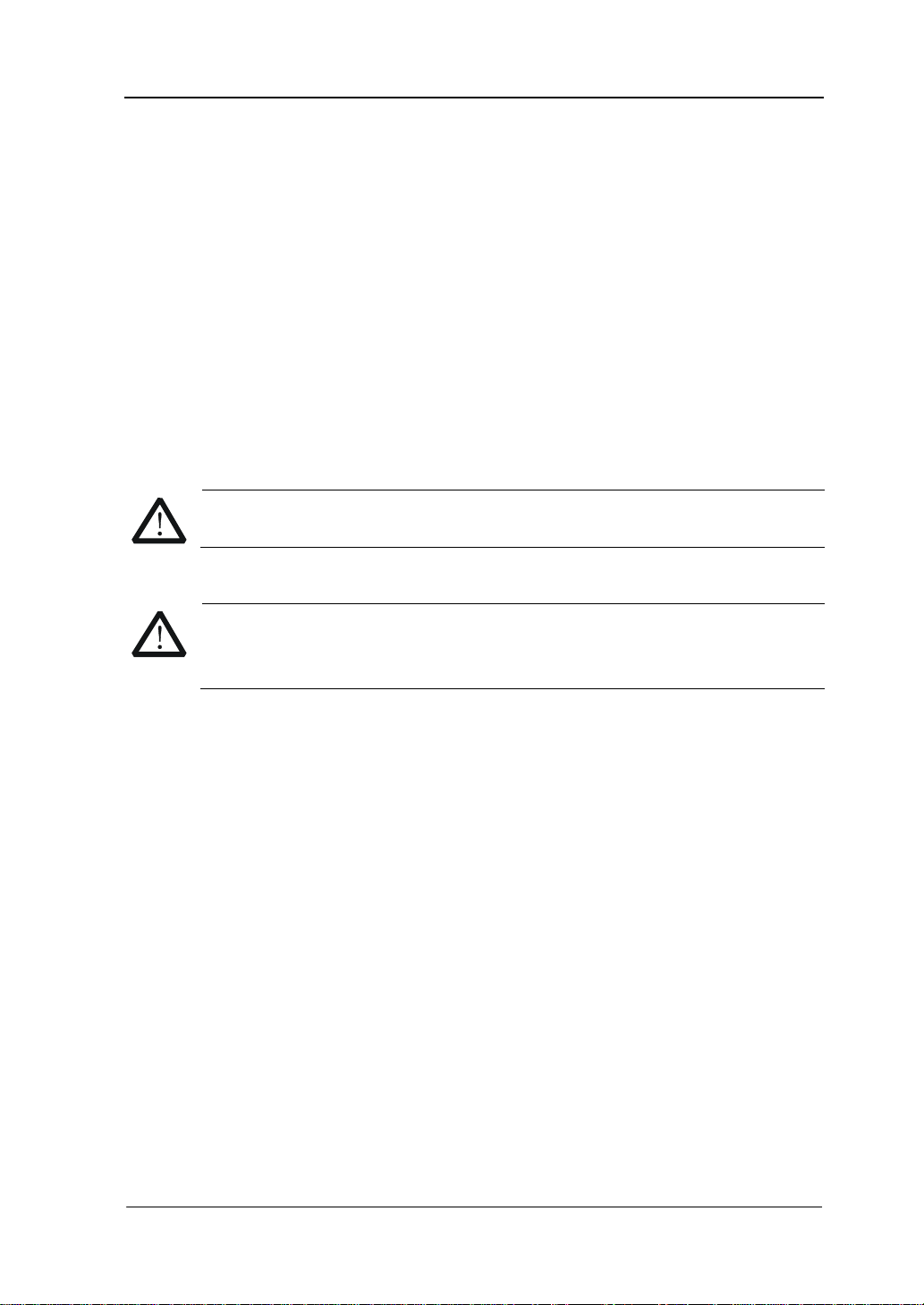
调整支撑脚
DG4000 允许用户在使用仪器时打开支撑脚以作为支架使仪器向上倾斜,便于操作和
观察。在不使用仪器时,用户可以合上支撑脚以方便放置或搬运。
支撑脚
图 1 打开支撑脚
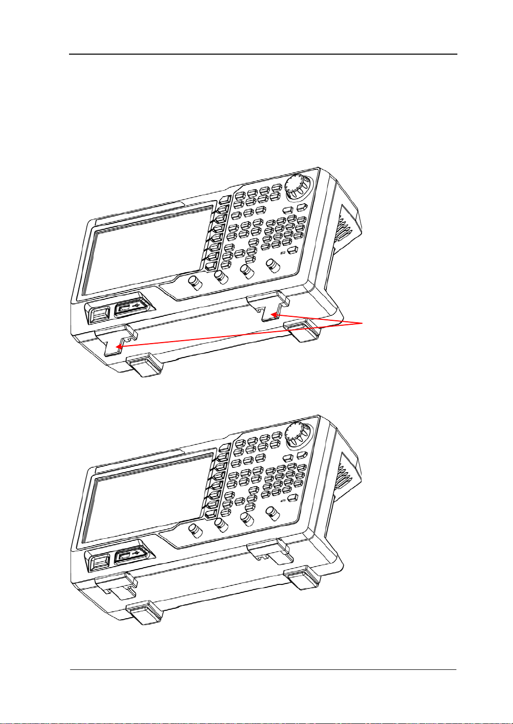
图 2 合上支撑脚
DG4000 快速指南
3
Page 14
RIGOL
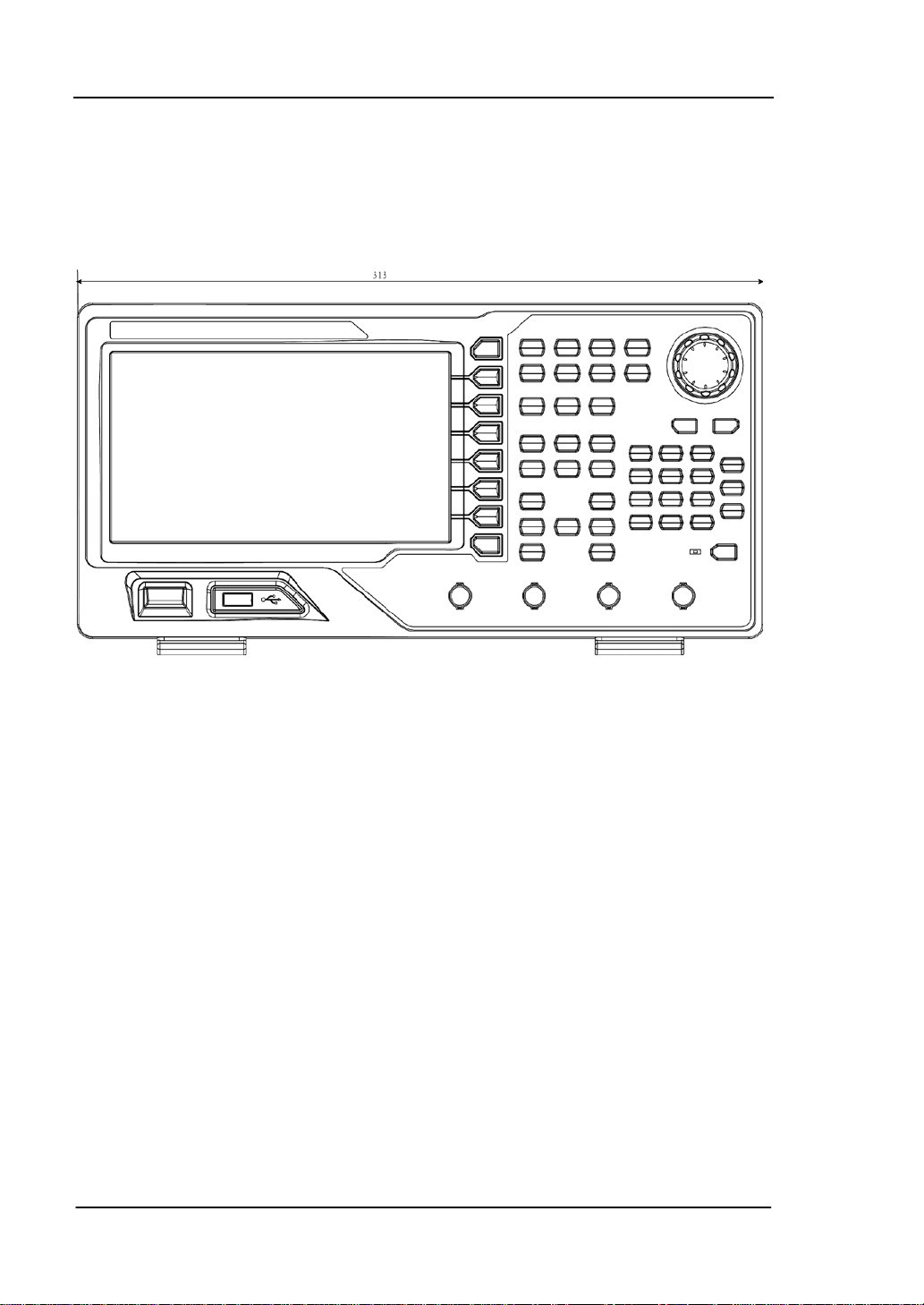
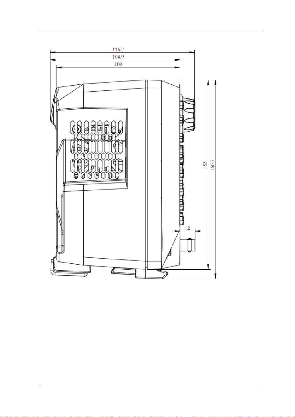
外观尺寸
DG4000 的外观与尺寸如图 3、图 4 所示。单位为 mm。
图 3 正视图
4
DG4000 快速指南
Page 15
RIGOL
图 4 侧视图
DG4000 快速指南
5
Page 16
RIGOL
1. 电源键
2. USB Host
3. 菜单软键
4. 菜单翻页 5. CH1输出端
6. CH1同步输出端
7. CH2输出端
8. CH2同步输出端
10. 频率计
11. 数字键盘
9. 通道控制区
12. 旋钮
13. 方向键
14. 波形选择区
15. 模式选择区
16. 返回上一级菜单
17. 快捷键/辅助功能键
18. LCD显示屏
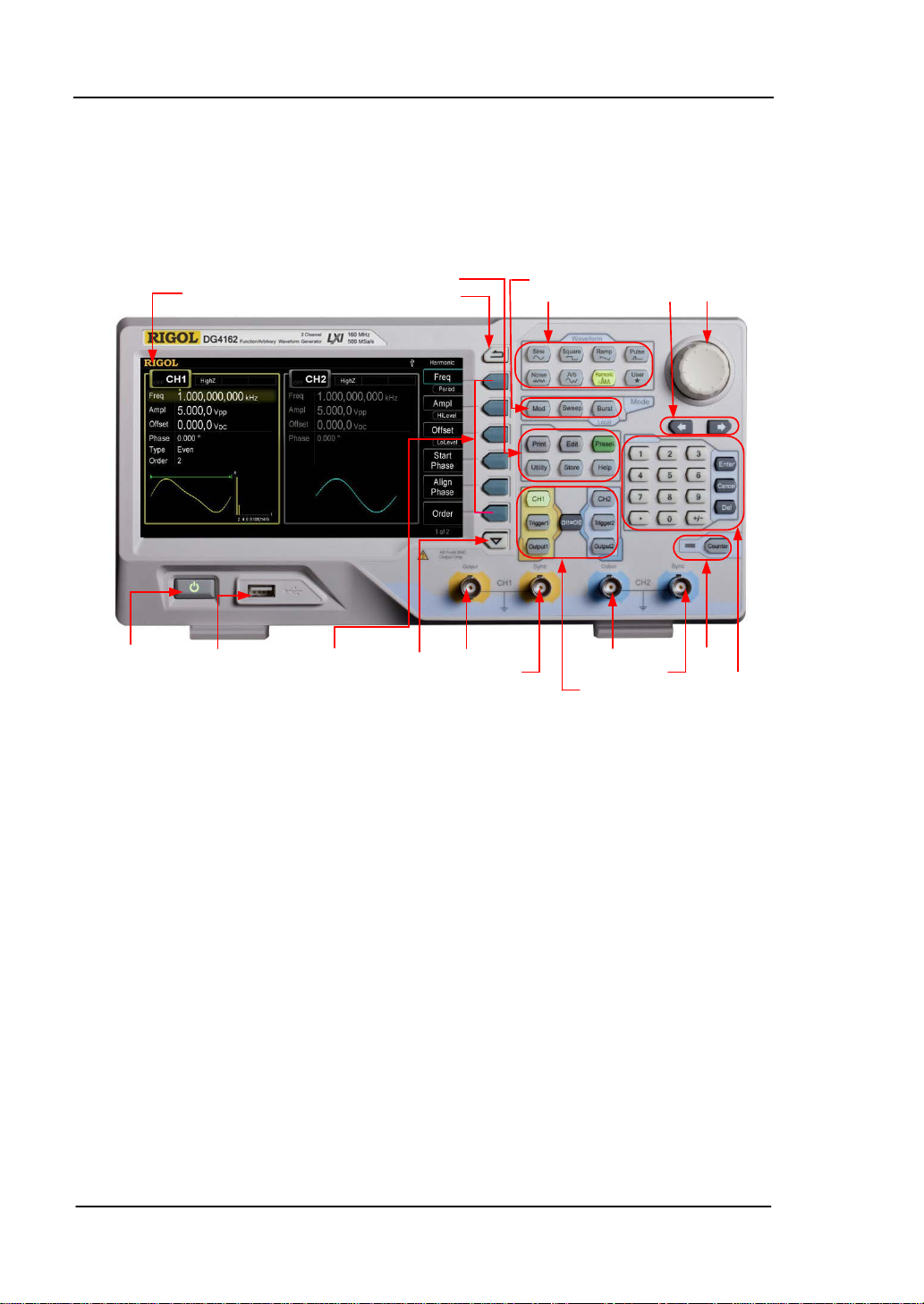
前面板
DG4000 前面板布局如下图所示。
图 5 DG4000 前面板
1. 电源键
用于开启或关闭信号发生器。当该电源键关闭时,信号发生器处于待机模式。只
有拔下后面板的电源线,信号发生器才会处于断电状态。
您可以启用或禁用该按键自身的功能。启用时,仪器上电后,需要手动按下该按
键启动仪器;禁用时,仪器上电后自动启动。
2. USB Host
支持 FAT 格式的 U 盘。读取 U 盘中的波形或状态文件,或将当前的仪器状态和编
辑的波形数据存储到 U 盘中,也可以将当前屏幕显示的内容以指定的图片格式
(.bmp 或.jpeg)保存到 U 盘。
3. 菜单软键
与其左侧菜单一一对应,按下任一软键激活对应的菜单。
6
DG4000 快速指南
Page 17
4. 菜单翻页
打开当前菜单的上一页或下一页。
5. CH1 输出端
BNC 连接器,标称输出阻抗为 50Ω。
当 Output1 打开时(背灯变亮),该连接器以 CH1 当前配置输出波形。
6. CH1 同步输出端
BNC 连接器,标称输出阻抗为 50Ω。
当 CH1 打开同步时,该连接器输出与 CH1 当前配置相匹配的同步信号。
7. CH2 输出端
BNC 连接器,标称输出阻抗为 50Ω。
当 Output2 打开时(背灯变亮),该连接器以 CH2 当前配置输出波形。
8. CH2 同步输出端
BNC 连接器,标称输出阻抗为 50Ω。
当 CH2 打开同步时,该连接器输出与 CH2 当前配置相匹配的同步信号。
9. 通道控制区
CH1:选择通道 CH1。选择后,背灯变亮,用户可以设置 CH1 的波形、参数和配
置。
CH2:选择通道 CH2。选择后,背灯变亮,用户可以设置 CH2 的波形、参数和配
置。
Trigger1:CH1 手动触发按键,在扫频或脉冲串模式下,用于手动触发 CH1 产生
一次扫频或脉冲串输出(仅当 Output1 打开时)。
Trigger2:CH2 手动触发按键,在扫频或脉冲串模式下,用于手动触发 CH2 产生
一次扫频或脉冲串输出(仅当 Output2 打开时)。
Output1:开启或关闭 CH1 的输出。
Output2:开启或关闭 CH2 的输出。
CH2:执行通道复制功能。
CH1
RIGOL
DG4000 快速指南
7
Page 18

RIGOL
10. 频率计
按下 Counter 按键,开启或关闭频率计功能。频率计功能开启时,Counter 按
键背灯变亮,左侧指示灯闪烁。若屏幕当前处于频率计界面,再次按下该键关闭
频率计功能;若屏幕当前处于非频率计界面,再次按下该键切换到频率计界面。
11. 数字键盘
用于输入参数,包括数字键 0 至 9、小数点“.”、符号键“+/-”、按键“Enter”、
“Cancel”和“ Del”。注意,要输入一个负数,需在输入数值前输入一个符号“-”。
此外小数点“.”还可以用于快速切换单位,符号键“+/-”用于切换大小写(关
于如何使用数字键盘输入参数,请参考“
参数设置方法”一节的介绍)。
12. 旋钮
在参数设置时,用于增大(顺时针)或减小(逆时针)当前突出显示的数值。
在存储或读取文件时,用于选择文件保存的位置或用于选择需要读取的文件。
在输入文件名时,用于切换软键盘中的字符。
此外,还可用于选择内置波形。
13. 方向键
在使用旋钮和方向键设置参数时,用于切换数值的位。
在文件名输入时,用于移动光标的位置。
14. 波形选择区
Sine——正弦波
提供频率从 1μHz 至 160MHz 的正弦波输出。
选中该功能时,按键背灯将变亮。
可以改变正弦波的“频率/周期”、“幅度/高电平”、“偏移/低电平”和“起始
相位”。
Square
——方波
提供频率从 1μHz 至 50MHz 并具有可变占空比的方波输出。
选中该功能时,按键背灯将变亮。
可以改变方波的“频率/周期”、“幅度/高电平”、“偏移/低电平”、“占空比”
和“起始相位”。
Ramp
——锯齿波
提供频率从 1μHz 至 4MHz 并具有可变对称性的锯齿波输出。
选中该功能时,按键背灯将变亮。
8
DG4000 快速指南
Page 19
可以改变锯齿波的“频率/周期”、“幅度/高电平”、“偏移/低电平”、“对称性”
和“起始相位”。
——脉冲波
Pulse
提供频率从 1μHz 至 40MHz 并具有可变脉冲宽度和边沿时间的脉冲波输出。
选中该功能时,按键背灯将变亮。
可以改变脉冲波的“频率/周期”、“幅度/高电平”、“偏移/低电平”、“脉宽/
占空比”、“上升沿”、“下降沿”和“延迟”。
Noise——噪声
提供带宽为 120MHz 的高斯噪声输出。
选中该功能时,按键背灯将变亮。
可以改变噪声的“幅度/高电平”和“偏移/低电平”。
——任意波
Arb
提供频率从 1μHz 至 40MHz 的任意波输出。
支持逐点输出模式。
可输出内建 150 种波形:直流、Sinc、指数上升、指数下降、心电图、高斯、
半正矢、洛仑兹、脉冲和双音频等。也可以输出 U 盘中存储的任意波形。
还可以输出用户在线编辑(16kpts)或通过 PC 软件编辑后下载到仪器中的任
意波。
选中该功能时,按键背灯将变亮。
可改变任意波的“频率/周期”、“幅度/高电平”、“偏移/低电平”和“起始相
位 ”。
Harmonic
——谐波
提供频率从 1μHz 至 80MHz 的谐波输出。
可输出最高 16 次谐波。
可以改变谐波的“频率/周期”、“幅度/高电平”、“偏移/低电平”和“起始相
位”。
可以设置“谐波次数”、“谐波类型”、“谐波幅度”和“谐波相位”。
——用户自定义波形键
User
用户可以将该按键定义为最常用的内建波形的快捷键(Utility 用户键), 此 后
便可以在任意操作界面,按下该键快速打开所需的内建波形并设置其参数。
RIGOL
DG4000 快速指南
9
Page 20

RIGOL
15. 模式选择区
Mod——调制
可输出经过调制的波形,提供多种模拟调制和数字调制方式,可产生 AM、FM、
PM、ASK、FSK、PSK、BPSK、QPSK、3FSK、4FSK、OSK 和 PWM 调制信号。
支持“内部”和“外部”调制源。
Sweep
——扫频
可产生“正弦波”、“方波”、“锯齿波”和“任意波(DC 除外)”的扫频信号。
支持“线性”、“对数”和“步进”3 种扫频方式。
支持“内部”、“外部”和“手动”3种触发源。
提供“标记”功能。
选中该功能时,按键背灯将变亮。
——脉冲串
Burst
可产生“正弦波”、“方波”、“锯齿波”、“脉冲波”和“任意波(DC 除外)”的脉
冲串输出。
支持“N 循环”、“无限”和“门控”3种脉冲串模式。
“噪声”也可用于产生门控脉冲串。
支持“内部”、“外部”和“手动”3种触发源。
选中该功能时,按键背灯将变亮。
注意,当仪器工作在远程模式时,该键用于返回本地模式。
16. 返回上一级菜单
该按键用于返回上一级菜单。
17. 快捷键/辅助功能键
Print——打印功能键
将屏幕以图片形式保存到 U 盘。
——编辑波形快捷键
Edit
该键是“Arb 编辑波形”的快捷键,用于快速打开任意波编辑界面。
Preset
——恢复预设值
用于将仪器状态恢复到出厂默认值或用户自定义状态。
10
DG4000 快速指南
Page 21
Utility——辅助功能与系统设置
注意
用于设置一些系统参数。
选中该功能时,按键背灯将变亮。
Store
——存储功能键
可存储/调用仪器状态或者用户编辑的任意波数据。
支持文件管理系统,可进行常规文件操作。
内置一个非易失性存储器(C 盘),并可外接一个 U 盘(D 盘)。
选中该功能时,按键背灯将变亮。
——帮助
Help
要获得任何前面板按键或菜单软键的上下文帮助信息,按下该键将其点亮后,再
按下你所需要获得帮助的按键。
18. LCD
800×480 TFT 彩色液晶显示器,显示当前功能的菜单和参数设置、系统状态以及
提示消息等内容。
RIGOL
通道输出端设有过压保护功能,满足下列条件之一则产生过压保护。
仪器幅度设置大于 4Vpp,输入电压大于±11.25V (±0.1V),频率小于
10kHz。
仪器幅度设置小于等于 4Vpp,输入电压大于±4.5V (±0.1V),频率小
于 10kHz。
产生过压保护时,仪器屏幕显示提示消息“过载保护,输出关闭!”。
DG4000 快速指南
11
Page 22
RIGOL
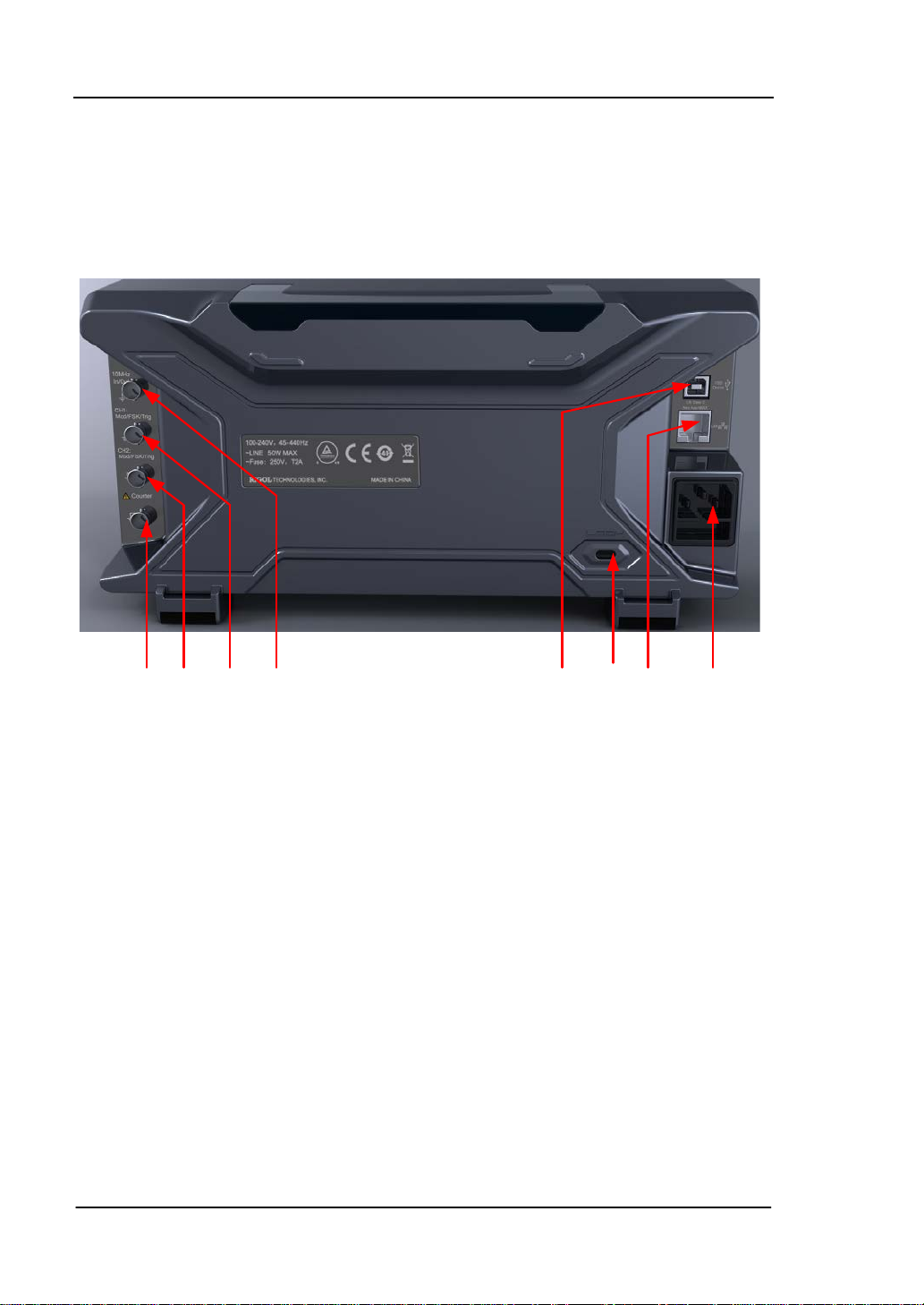
8. 7. 6. 5. 4. 3. 2. 1.
后面板
DG4000 的后面板布局如下图所示。
图 6 DG4000 后面板
1. AC 电源输入
本信号发生器支持的交流电源规格为:100-240V,45-440Hz。
2. LAN
通过该接口将信号发生器连接至局域网中,进行远程控制。本信号发生器符合
LXI-C 类仪器标准,可与其他标准设备快速搭建测试系统,轻松实现系统集成。
3. 防盗锁孔
使用防盗锁(请用户自行购买)可将仪器锁定在固定位置。
4. USB Device
通过该接口可连接 PC,通过上位机软件对信号发生器进行控制。
12
DG4000 快速指南
Page 23

5. 10MHz 输入/输出端(10MHz In/Out)
BNC 母头连接器,标称阻抗为 50Ω,其功能由仪器使用的时钟类型决定。DG4000
可以使用内部时钟或外部时钟。
若仪器使用内部时钟源,该连接器(用作 10MHz O ut)可输出由仪器内部晶
振产生的 10MHz 时钟信号。
若仪器使用外部时钟源,该连接器(用作 10MHz In)接收一个来自外部的
10MHz 时钟信号。
该连接器通常用于在多台仪器之间建立同步。
6. CH1 外调制/触发输入端(CH1:Mod/FSK/Trig)
BNC 母头连接器,标称阻抗为 50Ω,其功能由 CH1 当前的工作模式决定。
Mod:
若 CH1 开启 AM、FM、PM、PWM 或 OSK 且使用外部调制源,该连接器接
收一个来自外部的调制信号。
FSK:
若 CH1 开启 ASK、FSK 或 PSK 且使用外部调制源,该连接器接收一个来自外
部的调制信号(可设置该信号的极性)。
Trig In:
若 CH1 开启扫频或脉冲串功能且使用外部触发源,该连接器接收一个来自外
部的触发信号(可设置该信号的极性)。
Trig Out:
若 CH1 开启扫频或脉冲串功能且使用内部或手动触发源,该连接器输出具有
指定边沿的触发信号。
7. CH2 外调制/触发输入端(CH2:Mod/FSK/Trig)
BNC 母头连接器,标称阻抗为 50Ω,其功能由 CH2 当前的工作模式决定。
Mod:
若 CH2 开启 AM、FM、PM、PWM 或 OSK 且使用外部调制源,该连接器接收
一个来自外部的调制信号。
FSK:
若 CH2 开启 ASK、FSK 或 PSK 且使用外部调制源,该连接器接收一个来自外
部的调制信号(可设置该信号的极性)。
Trig In:
若 CH2 开启扫频或脉冲串功能且使用外部触发源,该连接器接收一个来自外
部的触发信号(可设置该信号的极性)。
Trig Out:
若 CH2 开启扫频或脉冲串功能且使用内部或手动触发源,该连接器输出具有
RIGOL
DG4000 快速指南
13
Page 24

RIGOL
指定边沿的触发信号。
8. 外部信号输入端(Counter)
BNC 母头连接器,标称阻抗为 50Ω,用于接收频率计测量的外部信号。
14
DG4000 快速指南
Page 25
RIGOL
注意
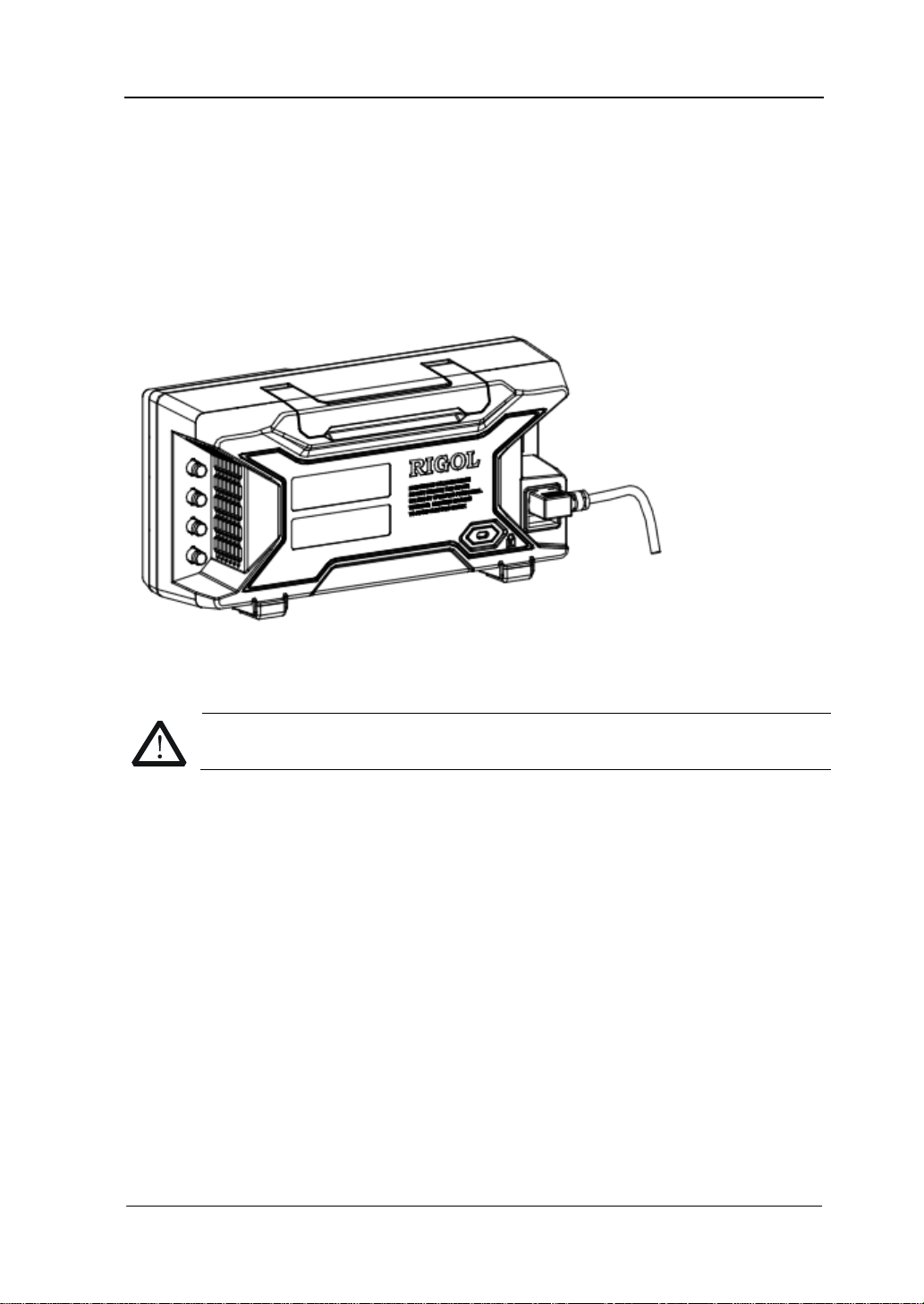
连接电源
DG4000 支持的交流电源规格为 100V 至 240V,45Hz 至 440Hz。请 使用附件提供的电
源线将仪器连接至交流电源中(如图 7 所示),此时,信号发生器已处于通电状态,
前面板左下角的电源键呈呼吸状态。
图 7 连接电源
如需更换电源保险丝,请将仪器返厂,由 RIGOL 授权的维修人员进行更换。
DG4000 快速指南
15
Page 26
RIGOL
警告
更换保险丝
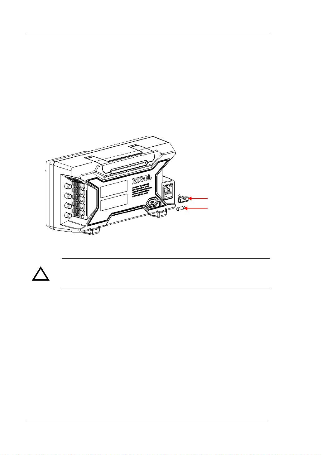
如需更换保险丝,请使用仪器指定规格的保险丝,按如下步骤更换:
1. 关闭仪器,断开电源,拔去电源线;
2. 使用小一字螺丝刀撬出保险丝座;
3. 取出保险丝座;
4. 更换指定规格的保险丝;
5. 重新安装保险丝座。
保险丝座
保险丝
图 8 更换保险丝
!
为避免电击,更换保险丝之前,请确保仪器已关闭并且已断开与电源的
连接,且确保更换的保险丝规格符合要求。
16
DG4000 快速指南
Page 27
RIGOL
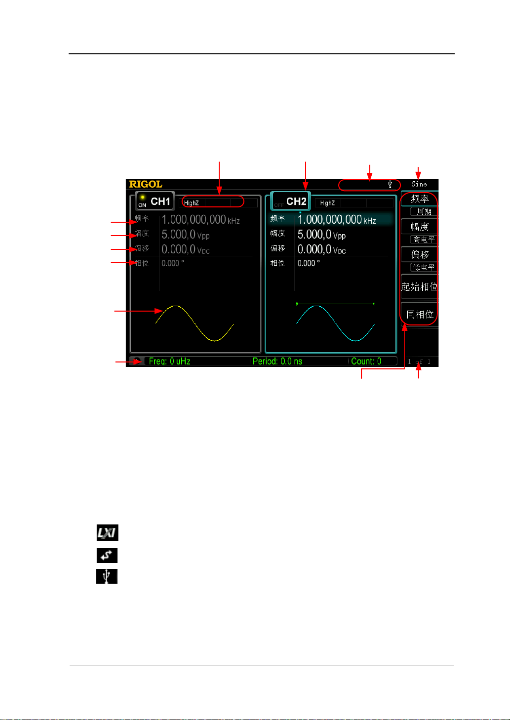
2. 状态栏 1. 当前功能
11. 菜单
4. 通道配置 3. 通道状态
5. 频率
6. 幅度
7. 偏移
8. 相位
9. 波形
10. 频率计
12. 菜单页码
用户界面
DG4000 用户界面同时显示两个通道的参数和波形。下图所示为 CH1 和 CH2 均选择正
弦波时的界面。基于当前功能的不同,界面显示的内容会有所不同。
图 9 用户界面
1. 当前功能
显示当前已选中功能的名称。例如:“Sine”表示当前选中“正弦波”功能,“ArbEdit”
表示当前选中“任意波编辑”功能。
2. 状态栏
基于当前的配置,状态栏将显示如下的指示符。
仪器正确连接至局域网时,点亮该标识。
仪器工作于远程模式时,点亮该标识。
仪器检测到 U 盘时,点亮该标识。
3. 通道状态
CH1 和 CH2 的显示区域,指示当前通道的选择状态和开关状态(ON/OFF)。
当前已选中通道的显示区域高亮显示;当前已打开通道的开关状态为“ON”。
DG4000 快速指南
17
Page 28

RIGOL
注意:
“选中”通道不同于“打开”通道。“选中 CH1”表示用户可以配置 CH1 的参数,
此时 CH1 背灯变亮;“打开 CH1”表 示 CH1 以当前配置输出波形,此时 Output1
背灯变亮。
4. 通道配置
显示各通道当前的输出配置,包括输出阻抗的类型、工作模式、调制或触发源的
类型。
输出阻抗
高阻:显示“HighZ”
负载:显示负载电阻值,默认为“50Ω”。
工作模式
调制:显示“Mod”
扫频:显示“Sweep”
脉冲串:显示“Burst”
调制类型/触发源
内部调制或内部触发源:显示“Internal”
外部调制或外部触发源:显示“External”
手动触发源:显示“Manual”
5. 频率
显示各通道当前波形的频率。按相应的 频率 菜单后,通过数字键盘或旋钮改变
该参数。当前可设置的参数会突出显示,数字上方的亮点表示光标处于当前位。
6. 幅度
显示各通道当前波形的幅度。按相应的 幅度 菜单后,通过数字键盘或旋钮改变
该参数。当前可设置的参数会突出显示,数字上方的亮点表示光标处于当前位。
7. 偏移
显示各通道当前波形的直流偏移。按相应的 偏移 菜单后,通过数字键盘或旋钮
改变该参数。当前可设置的参数会突出显示,数字上方的亮点表示光标处于当前
位。
8. 相位
显示各通道当前波形的相位。按相应的 起始相位 菜单后,通过数字键盘或旋钮
改变该参数。当前可设置的参数会突出显示,数字上方的亮点表示光标处于当前
位。
18
DG4000 快速指南
Page 29

9. 波形
显示各通道当前选择的波形。
10. 频率计
仅在开启频率计功能时存在。显示频率计当前的测量状态,包括简要和详细两种
显示模式。
简要:仅显示频率值、周期值和测量次数。
详细:显示当前频率计的配置、5 种测量值(频率、周期、占空比、正脉宽
和负脉宽)和测量次数。
11. 菜单
显示当前已选中功能对应的操作菜单。例如:图中显示“正弦波”功能菜单。
12. 菜单页码
显示当前菜单的页数和页码,如“1 of 1”或“1 of 2”。
RIGOL
DG4000 快速指南
19
Page 30

RIGOL
数字键
参数设置方法
参数设置可通过数字键盘或旋钮和方向键完成。
数字键盘
数字键盘由以下几部分组成:
数字键 0~9 用于直接输入所需的参数
值。
小数点
按下该键,当前光标处插入一个小数点“.”。
符号键
符号键“+/-”用于改变参数的符号。首次按下该键,参数符号为“-”, 再次按下
该键,符号切换为“+”。
注意,在编辑文件名时,符号键用于切换大小写。
Enter 键
用户输入参数过程中,按下该键将结束参数输入,并为参数添加默认的单位。
Cancel 键
(1) 参数输入过程中,按下该键将清除活动功能区的输入,同时退出参数输入状
态。
(2) 关闭活动功能区显示。
Del 键
(1) 参数输入过程中,按下该键将删除光标左边的字符。
(2) 在编辑文件名时,按下该键删除已输入的字符。
20
DG4000 快速指南
Page 31

方向键和旋钮
方向键功能包括:
1. 在参数输入时,方向键用于移动光标以选择当前编辑的位。
2. 在编辑文件名时,方向键用于移动光标的位置。
旋钮功能包括:
在参数可编辑状态,旋转旋钮将以指定
步进增大(顺时针)或减小(逆时针)
参数。
RIGOL
在编辑文件名时,旋钮用于选中软键盘中不同的字符。
在 Arb 选择波形 内建波形 中、 Arb 编辑波形 选择波形 和
Utility 用户键 中,旋钮用于选中不同的任意波。
在存储与调用功能中,旋钮用于选择文件保存的位置或用于选择需要读取的文
件。
DG4000 快速指南
21
Page 32

RIGOL
使用内置帮助系统
要获得任何前面板按键或菜单软键的帮助信息,首先按下 Help 键将其点亮,然后再
按下您所需要获得帮助的按键。
连续按两次 Help 键打开如下常用帮助信息。
1. 查看显示的最后一条信息
2. 查看远程命令错误队列
3. 获得任意键的帮助
4. 基本波形输出
5. 任意波形输出
6. 调制波形输出
7. 扫频输出
8. 突发输出
9. 存储管理
10. 同步多台仪器
11. RIGOL 技术支持
22
DG4000 快速指南
Page 33

RIGOL
使用防盗锁
使用防盗锁(选件)可将本仪器锁在固定位置。如下图所示,将锁对准仪器上的锁孔
插入,顺时针转动钥匙以锁定仪器,然后拔出钥匙。
图 10 防盗锁孔
防盗锁孔
DG4000 快速指南
23
Page 34

RIGOL
标号
名称
数量
零件编号
描述
使用机架
本仪器可安装到 19 英寸标准机柜内。
图 11 机架
部件清单
DG4000 机架(如图 11 所示)的部件清单如下表所示。其中,“标号”一栏与图 12、
图 13 对应。
表 1 机架部件清单
1-1
1-2
1-3
1-4
1-5
1-6
2-1
2-2
2-3
前面板
底板
左侧板
右侧板
压脚
固定件
M4 螺钉
M6 螺钉
M6 螺母
1 RM-DG4-01
1 RM-DG4-02
1 RM-DG4-03
1 RM-DG4-04
2 RM-DG4-05
2 RM-DG4-06
18 RM-SCREW-01
4 RM-SCREW-02
4 RM-SCREW-03
M4 x 6 十一字切沟盘头机械牙螺钉
M6 x 20十一字切沟盘头机械牙螺钉
M6 x 4 带定位锁片机械牙方螺母
24
DG4000 快速指南
Page 35

RIGOL
图 12 机架部件
2-1 2-2 2-3
图 13 螺钉与螺母
安装工具
推荐使用 PH2 号头十字改锥。
DG4000 快速指南
25
Page 36

RIGOL
安装空间
本机架安装到机柜内须满足如下要求:
机柜必须为 19 英寸标准机柜。
机柜至少有 4U 的空间(177.8 mm)。
机柜内深度至少 180 mm。
仪器上架后的尺寸如下图所示:
26
DG4000 快速指南
Page 37

RIGOL
安装步骤
仅授权人员方可执行安装操作,不正确的操作可能导致仪器损坏或者不能正确安装到
机架内。
DG4000 快速指南
27
Page 38

RIGOL
1. 安装左右侧板:左右侧板的卡位对准底板的豁口后插入底板,用 4 颗 M4 螺钉将
其固定。
2. 安装机架前面板:将前面板用 6 颗 M4 螺钉固定在上一步装好的框架上。
3. 固定仪器脚部:用两个压脚将仪器紧扣在底板上,用 4 颗 M4 螺钉将其固定。
28
DG4000 快速指南
Page 39

4. 固定仪器上部:将两个固定件压紧仪器上部,用 4 颗 M4 螺钉固定。
RIGOL
5. 装入机柜:用 4 颗 M6 螺钉和 4 颗 M6 方螺母将固定好仪器的机架安装在 19 英寸
标准机柜内。
DG4000 快速指南
29
Page 40

RIGOL
6. 安装后注意:机架占 4U 高度,箭头所指的孔为机架的安装孔,注意对准安装。
30
DG4000 快速指南
Page 41

RIGOL
故障处理
下面列举了 DG4000 在使用过程中可能出现的故障及排查方法。当您遇到这些故障时,
请按照相应的步骤进行处理,如不能处理,请与 RIGOL 公司联系,同时请提供您机
器的设备信息(获取方法:Utility System 系统信息)。
1. 如果按下电源开关信号发生器仍然黑屏,没有任何显示:
(1) 检查电源接头是否接好。
(2) 检查电源开关是否按实。
(3) 做完上述检查后,重新启动仪器。
(4) 如果仍然无法正常使用本产品,请与 RIGOL 联络。
2. 设置正确但无波形输出:
(1) 检查 BNC 电缆是否正常接在通道输出端口上([Output1] 或 [Output2])。
(2) 检查 BNC 线是否能够正常工作。
(3) 检查 Output1 或 Output2 键是否打开。
(4) 做完上述检查后,将 开机设置 设为“上次值”,然后重新启动仪器。
(5) 如果仍然无法正常使用本产品,请与 RIGOL 联络。
3. U 盘不能被识别:
(1) 检查 U 盘是否可以正常工作。
(2) 确认使用的为 Flash 型 U 盘,本仪器不支持硬盘型 U 盘。
(3) 重新启动仪器后,再插入 U 盘进行检查。
(4) 如果仍然无法正常使用 U 盘,请与 RIGOL 联络。
DG4000 快速指南
31
Page 42

Page 43

RIGOL
Quick Guide
DG4000 Series
Function/Arbitrary Waveform Generator
Feb. 2014
RIGOL Technologies, Inc.
Page 44

Page 45

RIGOL
Guaranty and Declaration
Copyright
© 2011 RIGOL Technologies, Inc. All Rights Rese rved.
Trademark Information
RIGOL is a registered trademark of RIGOL Technologies, Inc.
Publication Number
QGB04106-1110
Notices
RIGOL products are protected by patent law in and outside of P.R.C.
RIGOL reserves the right to modify or change parts of or all the specifications
and pricing policies at company’s sole decision.
Information in this publication replaces all previously corresponding m a t erial.
RIGOL shall not be liable for losses caused by either in cidental or consequential
in connection with the fu r nis hing , use or perfo rman ce of this manual as well as
any information contained.
Any part of this document is forbidden to cop y or photocopy or rearrange
without prior written approval of RIGOL.
Product Certification
RIGOL guar antees this pr oduct confo rms to the national and industrial stan dar ds in
China as well as the ISO9001:2008 standard and the ISO14001:2004 standard.
Other international standard conformance certification is in progress.
Contact Us
If you have any problem or requirement when using our products or this manual,
please contact RIGOL.
E-mail: service@rigol.com
Websites: www.rigol.com
Quick Guide for DG4000
I
Page 46

RIGOL
Safety Requirement
General Safety Summary
Please review the following safety precautions carefully before putting the
instrument into operation so as to avoid any personal injuries or damages to the
instrument and any product connecte d to it. To preve nt potential haza rds, please us e
the instrument only specified by this manual.
Use Proper Power Cord.
Only the power cord designed for the instrument and authorized for use within the
local country could be used.
Ground The Instrument.
The instrument is grounded through the Protective Earth lead of the power cord. To
avoid electric shock, it is e ssential t o connect the ea rth terminal of power cord to the
Protective Earth terminal before any inputs or outputs.
Connect the Probe Correctly.
If a probe is used, do not connect the ground lead to high voltage since it has the
isobaric electric potential as ground.
Observe All Terminal Ratings.
To avoid fire or shock hazard, observe all ratin gs and ma rkers on the ins trument and
check your manual for more inf o rmatio n abo ut ratings before connecting.
Use Proper Overvoltage Protection.
Make sure that no overvoltage (such as that caused by a thunderstorm) can reach
the product, or else the operator might expose to danger of electrical shock.
Do Not Operate Without C o ve r s.
Do not operate the instrument with covers or panels removed.
Do Not Insert Anything into the Holes of Fan.
Do not insert anything into the holes of the fan to avoid damaging the instrument.
II
Quick Guide for DG4000
Page 47

RIGOL
Use Proper Fuse.
Please use the specified fuse.
Avoid Circuit or Wire Exposure.
Do not touch exposed junctions and components when the unit is powered.
Do Not Operate With Suspected Failures.
If you suspect damage occurs to the instrument, have it inspected by qualified
service personnel before further operations. Any maintenance, adjustment or
replacement especially to circuits or accessories must be performed by RIGOL
authorized personnel.
Keep Well Ventilation.
Inadequate ventilation may cause increasing of temperature or damages to the
device. So please keep well ventilated and inspect the intake and fan regularly.
Do Not Operate in Wet Conditions.
In order to av oid short circuiting t o the interi or of the device or electric shock, please
do not operate in a humid environment.
Do Not Operate in an Explosive Atmosphere.
In order to avoid damages to the device or personal injuries, it is important to
operat e the dev ice away fro m an explosive at m osphere.
Keep Product Surfaces Clean and Dry.
To avoid the influence of dust and/or moisture in air, please keep the surface of
device clean and dry.
Electrostatic Prevention.
Operate in an electrostatic discharge protective area environment to avoid damages
induced by static discharges. Always ground both the internal and external
conductors of the cable to release static before connecting.
Proper Use of Battery.
If a battery is supplied, it must not be exposed to high temperature or in contact with
fire. Keep it out of the reach of children. Improper change of battery (note: lithium
battery) may cause explosion. Use RIGOL specified battery onl y.
Quick Guide for DG4000
III
Page 48

RIGOL
Handling Safety.
Please handle with care during transportation to avoid damages to buttons, knob
interfaces and other parts on the panels.
IV
Quick Guide for DG4000
Page 49

RIGOL
Warning state ments indicate the conditions or practices that could result i n
Hazardous
Safety
Protective
Chassis
Test
Safety Terms and Symbols
Terms Used in this Manual. These terms may appear in this manual:
WARNING
injury or loss of life.
CAUTION
Caution statements indicate the c onditions or practic es that coul d result i n
damage to this product or other property.
Terms Used on the Product. These terms may appear on the Product:
DANGER indicates an injury or hazard may immediately happen.
WARNING indicates an injury or hazard may be accessible potentially.
CAUTION indicates potential damage to the instrument or other property might
occur.
Symbols Used on the Product. These symbols may appear on the product:
Voltage
Warning
Earth
Terminal
Ground
Quick Guide for DG4000
Ground
V
Page 50

RIGOL
Allgemeine Sicherheits Informationen
Überprüfen Sie diefolgenden Sicherheitshinweise
sorgfältigumPersonenschädenoderSchäden am Gerätundan damit verbundenen
weiteren Gerätenzu vermeiden. Zur Vermeidung vonGefa hren, nutz e n Sie bitte d a s
Gerät nur so, wiein diesem Handbuchangegeben.
Um Feuer oder Verletzungen zu vermeiden, verwenden Sie ein
ordnungsgemäßes Netzkabel.
Verwenden Sie für dieses Gerät nur das für ihr Land zugelass ene u nd genehm igte
Netzkabel.
Erden des Gerätes.
Das Gerät ist durch den Schutzleiter im Netzkabel geerdet. Um Gefahren durch
elektrischen Schlag zu vermeiden , ist es unerlässlich, die Er dung durchzufüh ren. Erst
dann dürfen weitere Ein- oder Aus gä nge verbunden werden.
Anschluss einesTastkopfes.
Die Erdungsklemmen der Sonden sindauf dem gleichen Spannungspegel des
Instruments geerdet. SchließenSie die Erdungsklemmen an keine hohe Spannung
an.
Beachten Sie alle Anschlüsse.
Zur Vermeidung von Feuer oder Stromschlag, beachten Sie alle Bemerkungen und
Markierungen auf dem Instrument. Bef olgen Sie die Bedienun gsanleitung für weitere
Informationen, bevor Sie weitere Anschlüsse an das Instrument legen.
Verwenden Sie einen geeigneten Überspannungsschutz.
Stellen Sie sicher, daß keinerlei Überspannung (wie z.B. durch Gewitter verursacht)
das Gerät erreichen kann. Andernfallsbestehtfür de n Anwender d ie
GefahreinesStromschlages.
Nicht ohne Abdeckung einschalten.
Betreiben Sie das Gerät nicht mit entfernten Gehäuse-Abdeckungen.
Betreiben Sie das Gerät nicht geöffnet.
Der Betrieb mit offenen oder entfernten Gehäuseteilen ist nicht zulässig. Nichts in
entsprechende Öffnungen stecken (Lüfter z.B.)
Passende Sicherung verwenden.
Setzen Sie nur die spezifikationsgemäßen Sicherungen ein.
VI
Quick Guide for DG4000
Page 51

RIGOL
Vermeiden Sie ungeschützte Verbindungen.
Berühren Sie keine unisolierten Verbindungen oder Baugrup pen, wäh rend das Gerät
in Betrieb ist.
Betreiben Sie das Gerät n ic h t im Fehlerfa ll .
Wenn Sie am Gerät einen Defekt vermuten, sorgen Sie dafür, bevor Sie das Gerät
wieder betreiben, dass eine Untersuchu ng durch qual ifiziertes Kundendienstpersonal
durchgeführt wird.Jedwede Wartung, Einstellarbeiten oder Austausch von Teilen am
Gerät, sowie am Zubehör dürfen nur von RIGOL autorisiertem Personal
durchgeführt werden.
Belüftung sicherstellen.
Unzureichende Belüftung kann zu Temp eraturanstiegen und somit zu thermischen
Schäden am Gerät führen. Stellen Sie deswegen die Belüftung sicher und
kontrollieren regelmäßig Lüfter und Belüftungsöffnungen.
Nicht in feuc h te r Um g ebung betre iben.
Zur Vermeidun g von Kurzschluß im Geräteinne ren und Stromschlag betreiben Sie das
Gerät bitte niemals in feuchter Umgebung.
Nicht in explosiver Atmosphäre betreiben.
Zur Ve rm e idung von P e rs onen- und Sachschäden ist es unumgängli ch, das Ger ät
ausschließlich fernab jedweder explosiven At mosphäre zu betreiben.
Geräteoberflächen sauber und trocken halten.
Um den Einfluß von Staub und Feuchtigkeit aus der Luft auszuschließen, halten Sie
bitte die Geräteoberflächen sauber und trocken.
Schutz gegen elektrostatische Entladung (ESD).
Sorgen Sie für eine elektrostatisch geschützte Umgebung, um somit Sch äden und
Funktionsstörungen durch ESD zu vermeiden. Erden Sie vor dem Anschluß immer
Innen- und Außenleiter der V erbindungsleitung, um st atische Aufladung zu entladen.
Die richtige Verwendung desAkku.
Wenneine Batterieverwendet wird, vermeiden Sie hohe Temperaturen bzw. Feuer
ausgesetzt werden.Bewahren Sie es außerhalbder Reichweitevon Kindern
auf . UnsachgemäßeÄnderung derBatterie(Anmerkun g:Lithium-Batterie)kann zu einer
Explosion führen. VerwendenSie nur von RIGOLangegebenenAkkus.
Sicherer Transport.
Transportieren Sie das Gerät sorgfältig (Verpackung!), um Schäden an
Bedienelementen, Anschlüssen und anderen Teilen zu vermeiden.
Quick Guide for DG4000
VII
Page 52

RIGOL
WARNING
CAUTION
DANGER
weist auf eine Verletzung ode r Gefäh r dun g hin, die sof ort
WARNING
Sicherheits Begriffe und Symbole
Begriffe in diesem Guide. Diese Begriffe können in diesem Handbuch
auftauchen:
Die Kennzeichnung WARNING beschreibt Gefahrenq ue llen die leibliche
Schäden oder den Tod von Personen zur Folge haben können.
Die Kennzeichnung Caution (Vorsicht) beschreibt Gefahrenquellen die
Schäden am Gerät hervorrufen können.
Begriffe auf dem Produkt. Diese Bedingungen können auf dem Produkt
erscheinen:
geschehen kann.
w eist auf eine Verletzun g oder Gefährdung hin, die möglicherweise
nicht sofort geschehen.
CAUTION bedeutet, dass eine mö gliche Beschädig ung des Instruments oder
anderer Gegenstände auftreten kann.
Symbole auf dem Produkt. Diese Symbole können auf dem Produkt
erscheinen:
GefährlicheS
pannung
SicherheitsHinweis
Schutz-erde Gehäusemasse Erde
VIII
Quick Guide for DG4000
Page 53

RIGOL
To avoid damages to the instrument, do not expose them to liquids which
General Care and Cleaning
General Care
Do not leave or store the instrument exposed to direct sunlight for long periods of
time.
Cleaning
Clean the instrument regularly according to its operating conditions. To clean the
exterior surface, perform the following steps:
1. Disconnect the instrument from all power sources.
2. Clean the loose dust on th e outside of the instr ument with a lint - free cloth (with
mild detergent or water). When cleaning t h e L C D, t ake c ar e to avo id sc ar ifying
it.
CAUTION
have causticity.
WARNING
To avoid injury resulting from short circuit, make sure the instrument is
completely dry before reconnecting into a power sour ce.
Quick Guide for DG4000
IX
Page 54

RIGOL
Environmental Consideratio ns
The following symbol indicates that this product complies with the WEEE Directives
2002/96/EC.
Product End-of-Life Handling
The equipment may contain substances that could be ha rmful to the envi ronme nt or
human health. In order to avoid release of such substances into the environment and
harmful to human health, we encourage you to recycle this product in an appr opriate
system that will ensure that most of the materials are reused or recycled
appropriately. Please contact your local authorities for disposal or recycling
information.
X
Quick Guide for DG4000
Page 55

RIGOL
Contents
Guaranty and Declaration ......................................................................... I
Safety Requirement ................................................................................ II
General Safety Summary ........................................................................... II
Safety Terms and Symbols ........................................................................ V
Allgemeine Sicherheits Informationen ........................................................ VI
Sicherheits Begriffe und Symbole ............................................................ VIII
General Care and Cleaning ....................................................................... IX
Environmental Considerations .................................................................... X
Quick Start ............................................................................................... 1
General Inspection ................................................................................... 2
To Adjust the Supporting Legs ................................................................... 3
Appearance and Dim ensions ...................................................................... 4
Front Panel .............................................................................................. 6
Rear Panel .............................................................................................. 13
To Connect to Power ................................................................................ 16
To Replace the Fuse ................................................................................ 17
User Interface ......................................................................................... 18
Parameter Setting Method ........................................................................ 21
Numeric Keyboard............................................................................. 21
Direction keys and Knob .................................................................... 22
To Use the Built-In Help ........................................................................... 23
To Use the Security Lock .......................................................................... 24
To Use the Rack Mount Kit ....................................................................... 25
Kit Parts List ..................................................................................... 25
Installation Tool ................................................................................ 26
Installation Space ............................................................................. 27
Installation Procedure ....................................................................... 30
Troubleshooting ..................................................................................... 34
Quick Guide for DG4000
XI
Page 56

Page 57

RIGOL
Quick Start
This chapter introduces the front/rear panel, user interface and parameter setting
method, as well as announcements during first use of the instrument.
Subjects in this chapter:
General Inspection
To Adjust the Supporting Legs
Dimensions
Front Panel
Rear Panel
To Connect to Power
To Replace the Fuse
User Interface
Parameter Setting Method
To Use the Built-In Help
To Use the Security Lock
To Use the Rack Mount Kit
Quick Guide for DG4000
1
Page 58

RIGOL
General Inspection
1. Inspect the shipping container for damage.
If there are damages in the container or foam, keep them until the whole
machine and the accessories pass the electrical and mechanical tests.
If your instrument has damaged during shipping, please contact your shipper
and carrier f or co mpensation . RIGOL will provide no free repa ir or replace ment.
2. Inspect the instrument.
In case of any mechanical damage or defect, or if the instrument does not
operate properly or pass the electrical and mechanical tests, contact your local
sales representative of RIGOL.
3. Check the Accessories
If the contents are incomplete or damaged, please contact your local sales
representative of RIGOL.
2
Quick Guide for DG4000
Page 59

RIGOL
To Adjust the Supporting Legs
DG4000 allows users to unfold the supporting legs as stands to tilt the generator
upwards for easier operation and observation during operation. Users can fold the
supporting legs for easier storage or carry when the instrument is not in use.
Figure 1 Unfold the Supporting Legs
Figure 2 Fold the Supporting Legs
Supporting Legs
Quick Guide for DG4000
3
Page 60

RIGOL
Appearance and Dimensions
The appearance and dimensions of DG4000 are as shown in Figure 3 and Figure 4
and the unit is mm.
Figure 3 Front View
4
Quick Guide for DG4000
Page 61

RIGOL
Figure 4 Side View
Quick Guide for DG4000
5
Page 62

RIGOL
1. Power Key
2. USB Host
3. Menu Softkey
4. Page Up/Down
5. CH1 Output
6. CH1 Sync Output
7. CH2 Output
8. CH2 Sync Output
10. Counter
11. Numeric
Keyboard
9. Channels Control
12. Knob
13. Direction
Keys
14. Waveforms
15. Modes
16. Return
17. Shortcuts/Utility
18. LCD
Front Panel
The front panel of DG4000 is shown below.
Figure 5 DG4000 Front Panel
1. Power Key
The power softkey is used to turn the generator on or off. When the power
softkey is turned off, the generator is in standby mode and the generator is in
power-off mode only when the power cable at the rear panel is pulled out.
Users can enable or disable the function of this softkey. When enabled, users
need to press this softkey to start the instrument after power-on; when disabled,
the instrument starts automaticall y aft er powe r-on.
2. USB Host
Support FAT file format USB storage device. Read the waveform or state files
from th e USB storage device, or store the current instrument state and edited
waveform data into the USB storage device, or store the content currently
displayed on the screen in specified picture format (.bmp or .jpeg) in USB
storage device.
6
Quick Guide for DG4000
Page 63

3. Menu Softkey
Correspond to the left menus respectively. Press any softkey to activate the
corresponding menu.
4. Page Up/Down
Open the previous or next page of the current function menu.
5. CH1 Output
BNC connector with 50Ω nominal output impedance.
When Output1 is enabled (the backlight turns on), this connector outputs
waveform according to the current configuration of CH1.
6. CH1 Sync Output
BNC connector with 50Ω nominal output impedance.
When the sync output of CH1 is enabled, this connector outputs the sync signal
corresponding to the current settings of CH1.
7. CH2 Output
BNC connector with 50Ω nominal output impedance.
When Output2 is enabled (the backlight turns on), this connector outputs
waveform according to t he current configuration of CH2.
8. CH2 Sync Output
BNC connector with 50Ω nominal output impedance.
When the sync output of CH2 is enabled, this connector outputs the sync signal
corresponding to the current settings of CH2.
9. Channels Control
CH1: used to select CH1. When CH1 is selected (the backlight turns on), users
can set the waveform and parameters of CH1.
CH2: used to select CH2. When CH2 is selected (the backlight turns on), users
can set the waveform and parameters of CH2.
Trigger1: in sweep or burst mode, it is used to trigger CH1 to generate a sweep
or burst output manually (only when Output1 is enabled).
RIGOL
Quick Guide for DG4000
7
Page 64

RIGOL
Trigger2: in sweep or burst mode, it is used to trigger CH2 to generate a sweep
or burst output manually (only when Output2 is enabled).
Output1: enable or disable the output of CH1.
Output2: enable or disable the output of CH2.
CH1
CH2: execute channel copy.
10. Counter
Press Counter to turn the counter on or of f. When the counter is turned on , the
backlight of the key is illuminated and the left indicator flickers. If the counter
interface is currently displayed, press this key again to disable counter function;
if the screen currently displays interfaces other t han the counter interface , p r es s
this key again to switch to counter interface.
11. Numeric Keyboard
It is used to input pa ramete rs and consists of numbers (0 to 9), decim al point (.),
operators (+/-) and buttons (“Enter”, “Cancel” and “Del”). If a negative is
required, please input an operator “-” before the numbers. In addition, the
decimal point “.” can be used to switch units quickly and the ope rat ors “+/-” can
be used to switch between uppercase and lowercase (for the use method of the
numeric keyboard, refer to the introduction in Parameter Setting Method).
12. Knob
During parameter setting, it is used to increase (clockwise) or decrease
(counterclockwise) the current highlighted num ber.
It is used to select file storage location or select the file to be recalled when
storing or recalling file.
It is used to switch the character in the soft keyboard when entering filename.
In additional, it is also used to select built-in waveform.
13. Direction Keys
When using the knob and direction keys to set parameters, the direction keys are
used to switch the digits of the num ber.
During filename input, they are used to move the cur s or.
8
Quick Guide for DG4000
Page 65

14. Waveforms
Sine----Sine
Generate a Sine waveform with frequency from 1μHz to 160MHz.
When the function is enabled, the backlight of the button turns on.
Enable to change Frequency/Pe riod, Am plitude/H igh Lev el, Off set/Lo w Level
and Start Phase of the Sine waveform.
Square----Square
Generate a Square waveform with frequency from 1μHz to 50MHz and variab le
duty cycle.
When the function is enabled, the backlight of the button turns on.
Enable to cha nge F requency /Peri od, Ampl itude/Hi gh Lev el, Off set/Lo w Level ,
Duty Cycle and Start Phase of the Square waveform.
Ramp----Ramp
Generate a Ramp waveform with frequency from 1μHz to 4MHz and variable
symmetry.
When the function is enabled, the backlight of the button turns on.
Enable to cha nge F requency /Peri od, Ampl itude/Hi gh Lev el, Off set/Lo w Level ,
Symmetry and Start Phase of the Ramp waveform.
Pulse----Pulse
Generate a Pulse waveform with frequency from 1μHz to 40MHz and vari able
pulse width and edge time.
When the function is enabled, the backlight of the button turns on.
Enable to cha nge F requency /Peri od, Ampl itude/Hi gh Lev el, Off set/Lo w Level ,
Pulse Width/Duty Cycle, Leading Edge Time, Trailing Edge Time and Delay
of the Pulse waveform.
Noise----Noise
Generate a Gauss Noise with 120MHz bandwidth.
When the function is enabled, the backlight of the button turns on.
Enable to change Amplitude/High Level and Offset/Low Level of the Noise.
Arb----Arbitrary Waveforms
Generate an arbitrary waveform with freque ncy from 1μHz to 40MHz.
Provide Step-by-Step output mode.
RIGOL
Quick Guide for DG4000
9
Page 66

RIGOL
Generate 150 built-in waveforms: DC, Sinc, Exponential Rise, Exponential
Fall, ECG, Ga uss, Ha versin e, Lo rentz, Pulse , Dual-To ne etc.; output ar bitr ary
waveforms stored in USB storage device.
Generate ar bitr ary wa vef orms (1 6kpts ) edited online or th rough PC softw are
and then downloaded to the instrument by the users.
When the function is enabled, the backlight of the button turns on.
Enable to cha nge F requency /Peri od, Ampl itude/Hi gh Level, Offset/Low Level
and Start Phase of the arbitrary waveform.
Harmonic----Harmonic
Generate harmonics with frequency from 1μHz to 80MHz.
Output up to 16th order of harmonic.
Enable to cha nge F requency /Peri od, Ampl itude/Hi gh Lev el, Off set/Lo w Level
and Start Phase of harmonics.
Users can set the harmonic “Order”, “Type”, “Ampl” and “Phase”.
User----User-defined Waveform Key
Users can define the built-in waveform frequently used as shortcut (Utility
UserKey). And then, in any operation interfa ce, p re s s User to quickly open the
desired waveform and set its parameter s.
15. Modes
Mod----Modulation
Generate the modulated waveforms. Provide various analog modulation and
digital modulation modes and can generate AM, FM, PM, ASK, FSK, PSK, BPSK,
QPSK, 3FSK, 4FSK, OSK or PWM modulated signal.
Support internal and external modulations.
Sweep----Sweep
Generate the frequency sweeping signal of Sine, Square, Ramp and Arbitrary
Waveforms (except DC).
Support three sweep types: L i n e ar, Log and Step.
Support three trigger sources: Internal, External and Manual.
Provide the “Mark” function.
When the function is enabled, the backlight of the button turns on.
10
Quick Guide for DG4000
Page 67

Burst----Burst
Generate burst waveforms of Sine, Square, Ramp, Pulse and Arbitrary wa veform
(except DC).
Support three burst types: N Cycle, Infinite and Gated.
Noise can also be used to generate Gated burst.
Support three trigger sources: Internal, External and Manual.
When the function is enabled, the backlight of the button turns on.
Note: when the instrument i s working in remote m ode, press this key to return to
local mode.
16. Return
This key is used to return to the previous menu.
17. Shortcuts/Utility
Print: save the content shown on the screen as image in USB storage device.
Edit: this key is the shortcut of “Arb Edit Wf orm ” and is used to enter the
ArbEdit interface quickly.
Preset: used to return the instrument state to default or user-defined states.
Utility: used to set the par ameters of system. When this functio n is enabled, the
backlight of the button turns on.
Store: store or recall the instrument state or user-defined arb itrary da ta.
Support file management system to execute normal file operations.
Provide a built-in non-volatile memory (C Disk) and an external US B storage
device (D Disk).
When the function is enabled, the backlight of the button turns on.
Help: to get context help i nfor mation a bout any f ront -panel key or menu softkey,
press this key until it is illuminated and then press the desired key.
18. LCD
800 × 480 TFT color LCD is used to display the current function menu and
parameters setting, system state as well as prompt messages.
RIGOL
Quick Guide for DG4000
11
Page 68

RIGOL
CAUTION
Overvoltage protection of the output channel will take effect once any of
the following conditions is met.
Amplitude setting in the generator is greater than 4 Vpp; the input
voltage is greater than ±11.25 V (±0.1 V) and frequency is lower
than 10kHz.
Amplitude setting in the generator is lower than or equal to 4 Vpp;
the input voltage is greater than ±4.5 V (±0.1 V) and frequency is
lower than 10kHz.
The message “OverLoad protect, The output is off!” will appear on
the screen when overvoltage protection takes effect.
12
Quick Guide for DG4000
Page 69

Rear Panel
8. 7. 6. 5. 4. 3. 2. 1.
The rear panel of DG4000 is as shown in the figure below.
RIGOL
Figure 6 DG4000 Rear P anel
1. AC Power Input
This generator accepts the AC power supply: 100-240V, 45-440Hz.
2. LAN
Connect the generator to the local area network for remote control through this
interface. This generator conforms to LXI-C class instrument standards and can
quickly build test system with other devices to easily realize system integration.
3. Security Lock Hole
Users can use the security lock (buy it by themselves) to lock the instrument at a
fixed location.
4. USB Device
PC can be connected through this interface to control the generator remotely
through PC software.
Quick Guide for DG4000
13
Page 70

RIGOL
5. 10MHz In/Out
BNC female connector with 50Ω nominal impedance. The function of this
connector is determined by the t ype of clo ck used by the generator. DG4000 can
use internal or external clock.
When internal clock sou rce is used, the connector (used as 10MHz Out) can
output 10MHz clock signal generat ed by the internal cryst al oscillato r o f the
generator.
When external clock source is used, the connector (used as 10MHz In)
accepts a 10MHz external clock signal.
This connector is usually used to synchronize multiple instruments.
6. CH1: Mod/FSK/Trig
BNC female connector with 50Ω nominal impedance. Its function is determined
by the current working mode of CH1.
Mod:
If AM, FM, PM, PWM or OSK is enabled for CH1 and external modulation
source is used, this connector accepts an external modulation signal.
FSK:
If ASK, FSK or PSK is enabled for CH1 and external modulation source is
used, this connector accepts an external modulation signal (users can set
the polarity of the signal).
Trig In:
If CH1 is in sweep or burst mode and external trigger source is used, this
connector accepts an external trigger signal (users can set the polarity of
the signal).
Trig Out:
If CH1 is in sweep or burst mode and internal or manual trigger source is
used, this connector outputs a trigger signal with specified edge.
7. CH2: Mod/FSK/Trig
BNC female connector with 50Ω nominal impedance. Its function is determined
by the current working mode of CH2.
Mod:
If AM, FM, PM, PWM or OSK is enabled for CH2 and external modulation
source is used, this connector accepts an external modulation signal.
14
Quick Guide for DG4000
Page 71

FSK:
If ASK, FSK or PSK is enabled for CH2 and external modulation source is
used, this connector accepts an external modulation signal (users can set
the polarity of the signal).
Trig In:
If CH2 is in sweep or burst mode and external trigger source is used, this
connector accepts an external trigger signal (users can set the polarity of
the signal).
Trig Out:
If CH2 is in sweep or burst mode and internal or manual trigger source is
used, this connector outputs a trigger signal with specified edge.
8. External Signal Input (Counter)
BNC female connector with 50Ω nominal impedance. It is used to accept an
external signal to be measured by the counter.
RIGOL
Quick Guide for DG4000
15
Page 72

RIGOL
To Connect to Power
DG4000 accepts the AC power supply: 100V to 240V, 45Hz to 440Hz. Please use the
power cable provided in the accessories to connect the instrument to AC power (as
shown in Figure 7). At this point, the generator is powered on and the power butt on
at the lower-left corner of the front panel is in breathing state.
Figure 7 To Connect to Power
CAUTION
If the power fuse needs to be changed, please retu r n the instru ment back
to our factory and the RIGOL authorized operator will change it for you.
16
Quick Guide for DG4000
Page 73

RIGOL
To Replace the Fuse
To replace the fuse, please use the specif ied fuse and follow the steps below.
1. Turn off the instrument, cut off the power supply and remove the power cord.
2. Use a small straight screwdriver to prize out the fuse seat.
3. Take out the fuse seat.
4. Replace the specified fuse.
5. Install the fuse seat again.
Fuse Seat
Fuse
Figure 8 To Replace the Fuse
WARNING
To avoid electric shock, please make sure that the instrument has been
turned o ff a nd the power su pply has been cut o ff before replacing the
fuse. Besides, please make sure that the fuse to be installed meets the
requirement.
Quick Guide for DG4000
17
Page 74

RIGOL
2. Status Bar
1. Current
Function
12. Menu Page Number
3. Channel State4. Channel Configuration
5. Frequency
6. Amplitude
7. Offset
8. Phase
9. Waveform
10. Counter
11. Menu
to LAN successfully, this indicator
When the generator detects connected USB storage device, this
User Interface
DG4000 user interface displays the parameters and waveforms of the two channels
at the same time. The figure below is the interface when both CH1 and CH2 select
Sine. Different contents will be displayed when different functions are enabled.
Figure 9 User Interf a ce
1. Current Function
Display the name of the function currently selected. For example, “Sine”
indicates that “Sine” waveform function is currently selected and “ArbEdit”
indicates that “Arbitrary Waveform Edit” function is currently selected.
2. Status Bar
The following indicators would be displayed according to the current
configuration.
When the instrument is connected in
will light.
When the generator works in remote mode, this indicator will light.
18
indicator will light.
Quick Guide for DG4000
Page 75

3. Channel Status
Display areas of CH1 and CH2. Indicate whether the channel is selected and
turned on (ON/OFF).
The area of the channel currently selected is highlighted and the on/off state of
the channel currently turned on is “ON”.
Note:
When a channel is “Selected”, it does not mean that the channel is turned on.
When CH1 is selected, users can configure the parameters of CH1 and the
backlight of CH1 turns on. When CH1 is turned on, CH1 can output waveform
according to the current configuration and the backlight of Output1 turns on.
4. Channel Configurations
Display the current output configuration in each channel, including output
resistance, mode and type of modulating source or trigger source.
Output Resistance
High Impedance: display “HighZ”
Load: display the resistance value, the default is “50Ω”
Mode
Modulation: display “Mod”
Sweep: display “Sweep”
Burst: display “Burst”
Modulating/Trigger Source Type
Internal modulating/trigger: display “Internal”
External modulating/trigger: display “External”
Manual Trigger: display “Manual”
5. Frequency
Display the current waveform frequency in each channel. Press the
corresponding softkey Freq and use the numeric keyboard or direction keys and
knob to modify this para meter. The parameter that can be modified currently will
be highlighted and the lightspot above the number indicates current cursor
location.
6. Amplitude
Display the current waveform amplitude in each channel. Press the
RIGOL
Quick Guide for DG4000
19
Page 76

RIGOL
corresponding softkey Ampl and use the n umeric keyb oard or direction ke ys and
knob to modify this para meter. The parameter that can be modified currently will
be highlighted and the lightspot above the number indicates current cursor
location.
7. Offset
Display the current wa veform DC offse t in each ch annel. Press the correspondin g
softkey Offset and use the numeric keyboard or direction keys and knob to
modify this parameter. The parameter that can be modified currently will be
highlighted an d the lightspot above t he number in dicates current cursor locatio n.
8. Phase
Display the current waveform phase in each channel. Press the corresponding
softkey Start Phase and use the numeric keyboard or direction keys and knob
to modify this parameter. The parameter that can be modified currently will be
highlighted an d the lightspot above t he number in dicates current cursor locatio n.
9. Waveform
Display the currently selected waveform shape in each channel.
10. Counter
Only available when the counter is turned on and can display the current
measurement state of the counter briefly or in detail.
Brief: only display frequency, period and the number of measurements
performed.
Detail: display the conf igurations of the counter, five measurement values
(Frequency, Period, Duty Cycle, Positive Pulse Width and Negative Pulse
Width) and the number of measurements performed.
11. Menu
Display the operation menu correspondin g to the function currently selected. F or
example, the “Sine” function menu is displayed in the above figure.
12. Menu Page Number
Display the total number of pages and the current page number of the menu,
such as “1 of 1” or “1 of 2”.
20
Quick Guide for DG4000
Page 77

RIGOL
Parameter Setting Method
Users can use the numeric keyboard or knob and direction keys to set parameters.
Numeric Keyboard
The numeric keyboard consists of:
Number Keys
The 0 to 9 number keys are used to
directly input the desired parameter
value.
Decimal Point
Press this key to insert a decimal poin t “.” at the current position of the cursor.
Operator Key
The operator key “+/-” is used to modify the operator of the parameter. Press
this key to set the parameter operator to “-”; press this key again to switch the
operator t o “+”. Note that the operator key is used to switch between uppercase
and lowercase in filename edit.
Enter Key
Press this key to finish parameter input and add the default unit for the
parameter.
Cancel Key
(1) During parameter input, press this key to clear the input in the active
function area and exit parameter input.
(2) Turn the display in the active function area off.
Del Key
(1) During parameter input, press this k e y t o delet e the character at the left of
Quick Guide for DG4000
21
Page 78

RIGOL
to increase (clockwise) or reduce (counterclockwise)
the cursor.
(2) During filename edit, press this key to delete the characters input.
Direction keys and Knob
Functions of the direction keys:
1. During parameter input, use the direction keys to move the cursor to select the
digit to be edited.
2. During filename edit, use the direction keys to move the cursor.
Functions of the knob:
When the parameter is in editable state, turn the knob
the parameter with specif ied step.
During filename edit, use the knob to select the char acters in t he soft ke yboar d.
In Arb Select WformBuiltIn, Arb Edit WformSelect Wform and
Utility UserKey, use the knob to sel ect arbitrary waveform.
In store and recall, use the knob to select the storage location of the f ile or to
select the file to be recalled.
22
Quick Guide for DG4000
Page 79

RIGOL
To Use the Built-In Help
To g et c o ntext help information about any front-panel key or menu softkey, press
Help to illuminate the key and then press the desired key to get corresponding help.
Pressing Help twice will get the following common help.
1. View the last displayed message.
2. View error queue of the remote commands.
3. Get the help information of a key.
4. Generate a basic waveform.
5. Generate an arbitrary waveform.
6. Generate a modulated waveform.
7. Generate a frequency Sweep.
8. Generate a Burst waveform.
9. Storage management.
10. Synchronize multiple Generators.
11. Get technical support from RIGOL.
Quick Guide for DG4000
23
Page 80

RIGOL
To Use the Security Lock
Use the security lock (option) to lock the generator at a fixed location. As shown in
the figure below, align the lock with the lock hole and plug it into the lock hole
vertically, turn the key clockwise to lock the instrument and then pull the key out.
Figure 10 Security Lock Hole
Security Lock Hole
24
Quick Guide for DG4000
Page 81

To Use the Rack Mount Kit
This instrument can be installed into a standard 19 inches cabinet.
Figure 11 Rack Mount Kit
RIGOL
Kit Parts List
The part list of the rack mount kit (as shown in Figure 11) of DG4000 is as shown in
the table below. Wherein, the “No.” column corresponds to Figure 12 and Figure 13.
Table 1 Kit Parts List
No. Name Qty Part No. Description
1-1 Front Panel 1 RM-DG4-01
1-2 Support Board 1 RM-DG4-02
1-3 Left Plate 1 RM-DG4-03
1-4 Right Plate 1 RM-DG4-04
1-5 Pressure Feet 2 RM-DG4-05
1-6 Built-in Fitting 2 RM-DG4-06
2-1 M4 Screw 18 RM-SCREW-01 M4 x 6 Phil-Slot Pan Head Machine
Screw
2-2 M6 Screw 4 RM-SCREW-02 M6 x 20 Phil-Slot Pan H ead Machine
Screw
2-3 M6 Nut 4 RM-SCREW-03 M6 x 4 Square Machine Lock Nuts
Quick Guide for DG4000
25
Page 82

RIGOL
Figure 12 Parts of Rack Mount Kit
2-1 2-2 2-3
Figure 13 Screws and Nuts
Installation Tool
PH2 Phillips Screwdriver (recommended).
26
Quick Guide for DG4000
Page 83

RIGOL
Installation Space
The following requirements must be fulfilled by the machine cabinet in which the
instrument is mounted.
The machine cabinet must be a standard 19-inch one.
At least 4U (177.8 mm) space should be pro vide d by the machi ne ca binet.
The depth inside the machine cabinet should not be less than 180 mm.
The dimension of the instrument after being installed is as shown below.
Quick Guide for DG4000
27
Page 84

RIGOL
28
Quick Guide for DG4000
Page 85

RIGOL
Quick Guide for DG4000
29
Page 86

RIGOL
Installation Procedure
Only authorized operators can execute the installation operation. Improper
installation might result in damage of the instrument or incorrect installation of the
instrument on the rack.
1. Install the right and left plates: align the detents of the right and left plates with
the openings on the support board and insert them into the support board
respectively, then fix them with four M4 screws.
2. Install the front panel of the rack mount kit: fix the front panel onto the frame
installed in the previous step using six M4 screws.
30
Quick Guide for DG4000
Page 87

RIGOL
3. Fix the bottom of the instrument: fix the instrument onto the support board
using two pressure feet and four M4 screws.
4. Fix the top of the instrument: fix the top of the instrument using two built-in
fittings and four M4 screws.
Quick Guide for DG4000
31
Page 88

RIGOL
5. Load into the machine cabinet: mount the rack with the instrument fixed to it
into a standard 19-inch machine cabinet with four M6 screws and four M6
square nuts.
6. Post-installation notice: the rack occupies a height of 4U. The holes pointed o ut
by the arrows are installation holes. Note that they should be aligned with
during installation.
32
Quick Guide for DG4000
Page 89

RIGOL
Quick Guide for DG4000
33
Page 90

RIGOL
Troubleshooting
This chapter lists the commonly en count ered failures of DG4000 an d their solutions.
When you encounter thos e proble ms, please sol ve t hem f ollowing the correspondin g
steps. If the problem persists, please contact RIGOL and provide your device
information (Utility System Sys Info).
1. The screen is still dark (no display) after power on:
(1) Check if the power is correctly connected.
(2) Check if the power switch is really on.
(3) Restart the instrument after finishing the above inspections.
(4) If it does not work co rrectly, contact RIGOL fo r ou r service.
2. The settings are correct but no waveform is generated:
(1) Check if the BNC cable is correctly connected to the channel output
terminal ([Output1] or [Output2]).
(2) Check if the BNC cable can work correctly.
(3) Check the Output1 or Output2 button, if it is turned on.
(4) Set PowerOn as “Last” and then restart the instrument after finishing the
above inspections.
(5) If it does not work correctly, contact RIGOL for our service.
3. The USB storage device cannot be recognized:
(1) Check if the USB storage device can work normally.
(2) Make sure the USB storage device is USB flash storage device. The
generator doesn’t support hard drive-based USB storage device.
(3) Restart th e instr u m ent, reinsert the USB storage device and check it.
(4) If the USB storage device still can not be recognized, please contact
RIGOL.
34
Quick Guide for DG4000
 Loading...