

Page 1

Performance Verification Guide
DG2000 Series
Function/Arbitrary Waveform Generator
Aug. 2019
RIGOL (SUZHOU) TECHNOLOGIES INC.
Page 2

Page 3

RIGOL
I
Guaranty and Declaration
Copyright
© 2019 RIGOL (SUZHOU) TECHNOLOGIES INC. All Rights Reserved.
Trademark Information
RIGOL is a registered trademark of RIGOL (SUZHOU) TECHNOLOGIES INC.
Publication Number
PVB12100-1110
Notices
RIGOL produ cts are cov ered by P.R.C. and f oreign pa tents, issue d and pendin g.
RIGOL reserves the right to modify or change parts of or all the specifications
and pricing policies at the company’s sole decision.
Information in this publication replaces all previously released materials.
Information in this publication is subject to change without notice.
RIGOL shall not be liable for either incidental or consequential losses in
connection with the furnishing, use, or performance of this manual, as well as
any information contained.
Any part of th is d ocu ment is f orbi dden to be c opie d, ph oto copie d, o r rea r ran ged
without prior written approval of RIGOL.
Product Certification
RIGOL guarantees that this product conforms to the national and industrial
standards in China as well as the ISO9001:2015 standard and the ISO14001:2015
standard. Other international standard conformance certifications are in progress.
Contact Us
If you have any problem or requirement when using our products or this manual,
please contact RIGOL.
E-mail: service@rigol.com
Website: www.rigol.com
DG2000 Performance Verification Guide
Page 4

RIGOL
II
General Safety Summary
Please review the following safety precautions carefully before putting the
instrument into operation so as to avoid any personal injury or damage to the
instrument and any product connected to it. To prevent potential hazards, please
follow the instructions specified in this manual to use the instrument properly.
Use the BNC Output Connector Properly.
The BNC output connector on the f ront panel only allows to output the signal b ut not
to input the signal.
Use Proper Power Cord.
Only the exclusive power cord designed for the instrument and authorized for use
within the local country could be used.
Ground the Instrument.
The instrument is grounded th rou gh t he Protective Earth lead of the power cord. To
avoid e lectric shock, connect the earth terminal of the power cord to the Protective
Earth terminal before connecting any input or output terminals.
Connect the Probe Correctly.
If a probe is used, the probe ground lead must be connected to earth ground. Do not
connect the ground lead to hi gh volta ge. Imprope r way of connection could r esult in
dangerous voltages being present on the connectors, controls or other surfaces of
the oscilloscope and probes, which will cause potential hazards for operators.
Observe All Terminal Ratings.
To a void fire or shock hazard, obse rve all r atings an d markers on t he instru ment and
check your manual for more information about ratings before connecting the
instrument.
Use Proper Overvoltage Protection.
Ensure that no over voltage (su ch as that cause d by a bolt of lightni ng) can reach the
product. Otherwise, the operator might be exposed to the danger of an electric
shock.
Do Not Operate Without Covers.
Do not operate the instrument with covers or panels removed.
Do Not Insert Objects Into the Air Outlet.
Do not insert objects into the air outlet, as doing so may cause damage to the
instrument.
Use Proper Fuse.
Please use the specified fuses.
DG2000 Performance Verification Guide
Page 5

RIGOL
III
Avoid Circuit or Wire Exposure.
Do not touch exposed junctions and components when the unit is powered on.
Do Not Operate With Suspected Failures.
If you suspect that any damage may occur to the instrument, have it inspected by
RIGOL authorized personnel before further operations. Any maint enance,
adjustment or replacement especially to circuits or accessories must be performed
by RIGOL authorized personnel.
Provide Adequate Ventilation.
Inadequate ventilation may cause an increase of temperature in the instrument,
which would cause damage to the instrument. So please keep the instrument well
ventilated and inspect the air outlet and the fan regularly.
Do Not Operate in Wet Conditions.
To avoid short circuit inside the instrument or electric shock, never operate the
instrument in a humid environment.
Do Not Operate in an Explosive Atmosphere.
To avoid personal injuries or damage to the instrument, never operate the
instrument in an explosive atmosphere.
Keep Product Surfaces Clean and Dry.
T o a void dust or moisture from af fecting the pe rformance of the inst rument, keep th e
surfaces of the instrument clean and dry.
Prevent Electrostatic Impact.
Operate the instrume nt i n an el ectr ostatic dischar ge protectiv e e nvi ron ment to a void
damage induced by static discharges. Always ground both the internal and external
conductors of cables to relea s e sta t i c be fore makin g connections.
Use the Battery Properly.
Do not expose the battery (if available) to high temperature or fire. Keep it out of the
reach of children. Improper change of a battery (lithium battery) may cause an
explosion. Use the RIGOL specified battery only.
Handle with Caution.
Please handle with care during transportation to avoid damage to keys, knobs,
interfaces, and other parts on the panels.
DG2000 Performance Verification Guide
Page 6

RIGOL
IV
Document Overview
This manual is used to gui de users to corre ctly test the perfo rmance specifications of
DG2000 series function/arbitrary waveform generator. The performance verification
test mainly verifies whether DG2000 series can work normally and is within
specifications.
Main topics in th is Manual:
Chapter 1 Test Overview
This chapter introduces the preparations before the performance verification test,
the recommended test devic e s, the test result r ecord, the test notices a n d the
related information of the technical parameters.
Chapter 2 Performance Verification Test
This chapter introduces t he test method, p r oce du res and limits of e ac h performance
specif ication in details.
Appendix
The appendix provides the test results record forms and performance specifications
of DG2000 series function/arbitrary waveform generator.
Format Conventions in this Manual:
1. Keys:
2. Menu Labels:
3. Connectors:
4. Operation Procedures:
The keys on the front panel are usually denoted by the format of "Key Name
(Bold) + Text Box". For example, Pulse/Utility denotes the Utility key.
The menu labels are usually denoted by the format of "Menu Word (Bold) +
Character Shading". For example, System Setting.
The connectors on the front or rear panel are usually denoted by the format of
"Connector Name (Bold) + Square Bracket s (Bold)". For example, [Counter].
"" repre sents the next step of operation. For example, when the backlight of
the Shift key is illuminated, pressing Pulse/Utility System Sett in g
denotes that first press Pulse/Utility on the front panel, and then tap the
System Setting menu label.
DG2000 Performance Verification Guide
Page 7
RIGOL
V
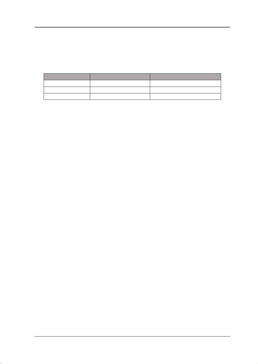
Model
No. of Channels
Max. Output Frequency
DG2052
2
50 MHz
DG2072
2
70 MHz
DG2102
2
100 MHz
Content Conventions in this Manual:
DG2000 series fun ction /arbitra ry w a vef orm gener ator in cludes the f ollowi ng m odels .
Unless otherwise noted in this manual, DG2102 is taken as an example to illustrate
the performance verification test methods of DG2000 series.
DG2000 Performance Verification Guide
Page 8

Contents RIGOL
VI
Contents
Guaranty and Declaration ......................................................................... I
General Safe ty Sum mary ......................................................................... II
Document Overview ............................................................................... IV
Chapter 1 Test Overview .................................................................... 1-1
Test P reparations ................................................................................... 1-1
Recommended Test Devices .................................................................... 1-1
Tes t Result Record ................................................................................. 1-2
Test Notices ........................................................................................... 1-2
Technical Parameters .............................................................................. 1-2
Chapter 2 Performance Verification Test ........................................... 2-1
Frequency Accuracy Test ......................................................................... 2-2
Specification ................................................................................... 2-2
Test Procedures ............................................................................... 2-2
Test Record Form ............................................................................ 2-3
AC Ampli t ude Accuracy Test .................................................................... 2-4
Specification ................................................................................... 2-4
Test Procedures ............................................................................... 2-4
Test Record Form ............................................................................ 2-5
DC Offset Accuracy Test .......................................................................... 2-6
Specification ................................................................................... 2-6
Test Procedures ............................................................................... 2-6
Test Record Form ............................................................................ 2-7
AC Flatness Test ..................................................................................... 2-8
Specification ................................................................................... 2-8
Test Procedures ............................................................................... 2-8
Test Record Form .......................................................................... 2-11
Harmonic Distortion Test ....................................................................... 2-12
Specification ................................................................................. 2-12
Test Procedures ............................................................................. 2-12
Test Record Form .......................................................................... 2-14
Spurious Signal Test ............................................................................. 2-15
Specification ................................................................................. 2-15
Test Procedures ............................................................................. 2-15
Test Record Form .......................................................................... 2-17
Rise/Fall Time Test ............................................................................... 2-18
Specification ................................................................................. 2-18
Test Procedures ............................................................................. 2-18
Test Record Form .......................................................................... 2-19
Overshoot Test .................................................................................... 2-20
Specification ................................................................................. 2-20
Test Procedures ............................................................................. 2-20
Test Record Form .......................................................................... 2-21
DG2000 Performance Verification Guide
Page 9

Contents RIGOL
VII
Appendix .................................................................................................. 1
Appendix A: Test Result Record Form ......................................................... 1
Appendix B: Performance Specifications ..................................................... 8
DG2000 Performance Verification Guide
Page 10

Page 11
Chapter 1 Test Overview RIGOL
1-1
Recommended
Instrument
>10MHz
Accuracy: 0.1ppm
Digital Multimeter
61/2 digits
RIGOL DM3068
-30dBm to +20dBm
Resolution: 0.01dB
Power Sensor
-30dBm to +20dBm
Keysight N8482A
Minimum resolution bandwidth i s
100Hz
Bandwidth: 500MHz
function
Power Sensor
Connecting Cable
Used to connect the power meter
and power sensor
Connecting Cable
BNC (m)-BNC (m)
--
Connecting Cable
BNC (m)-Dual banana plug (m)
--
50Ω Load
50Ω/1W
--
Adaptor
N (f)-BNC (m)
--
Adaptor
BNC (f)-N (m)
--
Chapter 1 Test Overview
Test Preparations
Before performing the test, make sure that the instrument is within the calibration
period (the recommended calibration period is 1 year) and has been warmed up for
at least 30 minutes under the specified operation temperature (18℃ to 28℃).
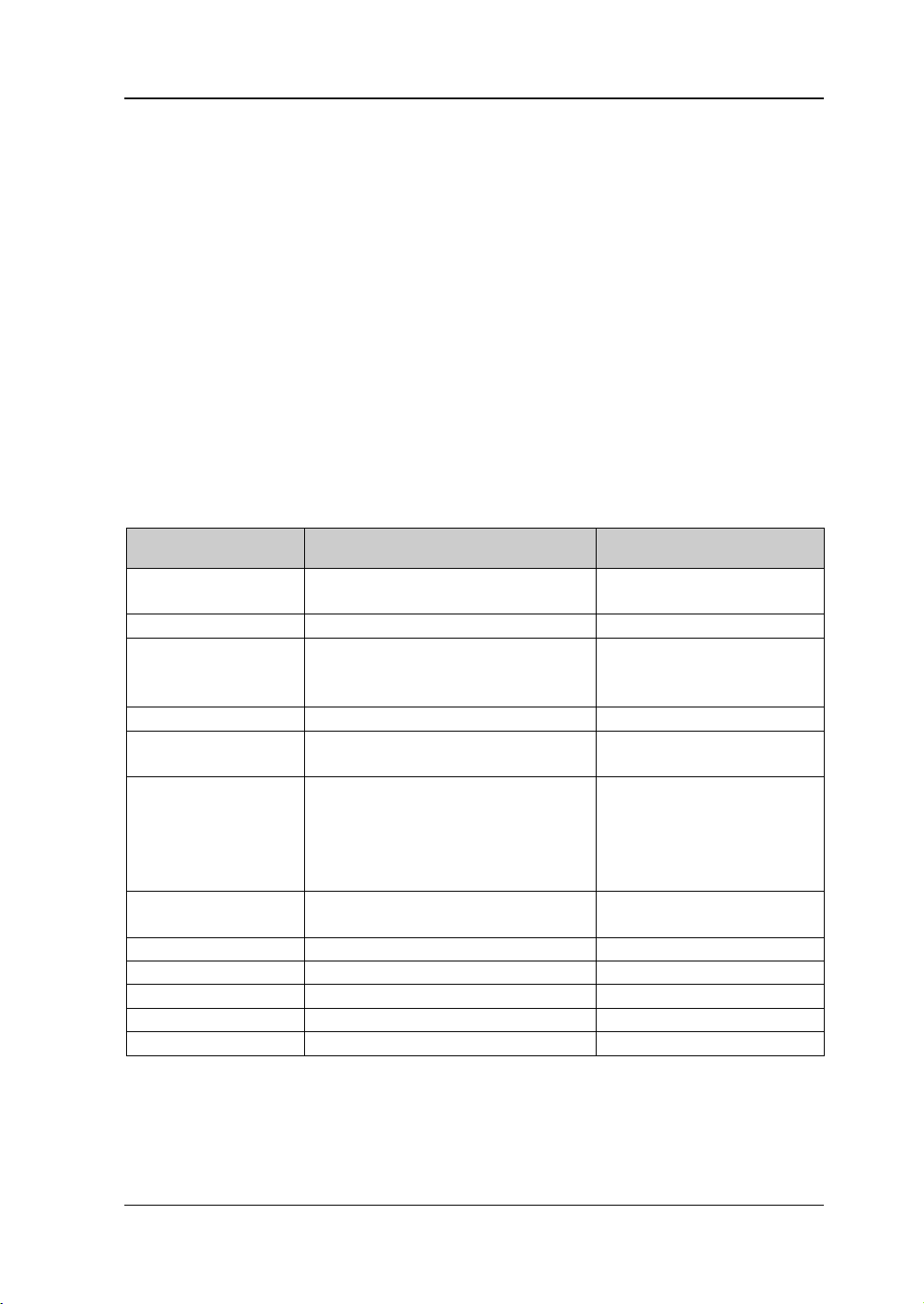
Recommended Test Devices
It is recommended that you use the test devices listed in the table below or other test
devices whose performance specifications satisfy the "Per formance Requirement"
listed in the table below to test the performance specifications of the DG2000 series.
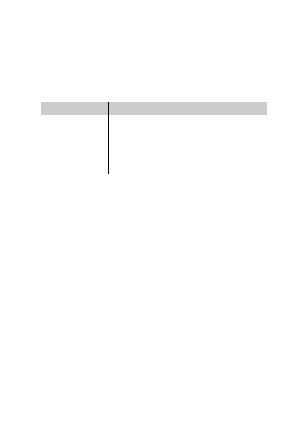
Table 1-1 Recommended test devices
Device Performance Requirement
Frequency Counter
Power Meter
Spectrum Analyzer
Oscilloscope
Accuracy: ±0.02dB
Rise/Fall time measurement
function
Overshoot measurement
Keysight 53131A
Keysight N1913A
RIGOL DSA815
RIGOL DS4052/DS4054
--
DG2000 Performance Verification Guide
Page 12

RIGOL Chapter 1 Test Overview
1-2
be used repeatedly.
Test Result Record
Record and keep the test results of each test item. The test result record forms,
which provide all the test items and the corresponding performance specification
limits as well as spaces for users to record the test results, are provid ed in
“Appendix A: Test Result Record Form” of this manual.
Tip:
It is recommended that you p hotocopy the test result record form bef ore each test.
During the test process, record the test results on the copies so that the forms can
Test Notices
To achieve optimum test effect, all the test procedures should follow the following
recommendations.
1) Make sure that the environment temperature is between 18℃ and 28℃ and
every test is performed under the specified operation temperature (18℃ to
28℃).
2) Before performing each test, make sure that the instrum ent has been warmed
up for at least 30 minutes.
3) Before performing each test, restore the instrument to factory setting.
Technical Parameters
Chapter 2 of this manual provides the corresponding specification of each test item.
Besides, "Appendix B: Performance Specifications" provides the detailed
performance specifications of DG2000 series.
DG2000 Performance Verification Guide
Page 13

Chapter 2 Performance Verification Test RIGOL
2-1
Chapter 2 Performance Verification Test
This chapter introduces the performance verification test methods of DG2000 series
function/arbitrary wa vefo rm gene rator by taking CH1 of DG2102 as an example. The
test methods are also applica b l e to CH2.
The test items include:
Frequency Accuracy Test
AC Amplitude Accuracy Test
DC Offset Accuracy Test
AC Flatness Test
Harmonic Distortion Test
Spurious Signal Test
Rise/Fall Time Test
Overshoot Test
DG2000 Performance Verification Guide
Page 14
RIGOL Chapter 2 Performance Verification Test
2-2
Frequency characteristic
Accuracy
±(1 ppm
[1]
of the setting value + 10 pHz), 18℃ to 28℃
Frequency Accuracy Test
Specification
[1]
Note
: ppm denotes one part per million. For example, if the setting frequency is 1MHz and the actual output
frequency is between 0.999 998 999 999 999 99MHz and 1.000 001 000 0 00 000 01MHz, the instru ment is u p
to the specification requirement and the test passes.
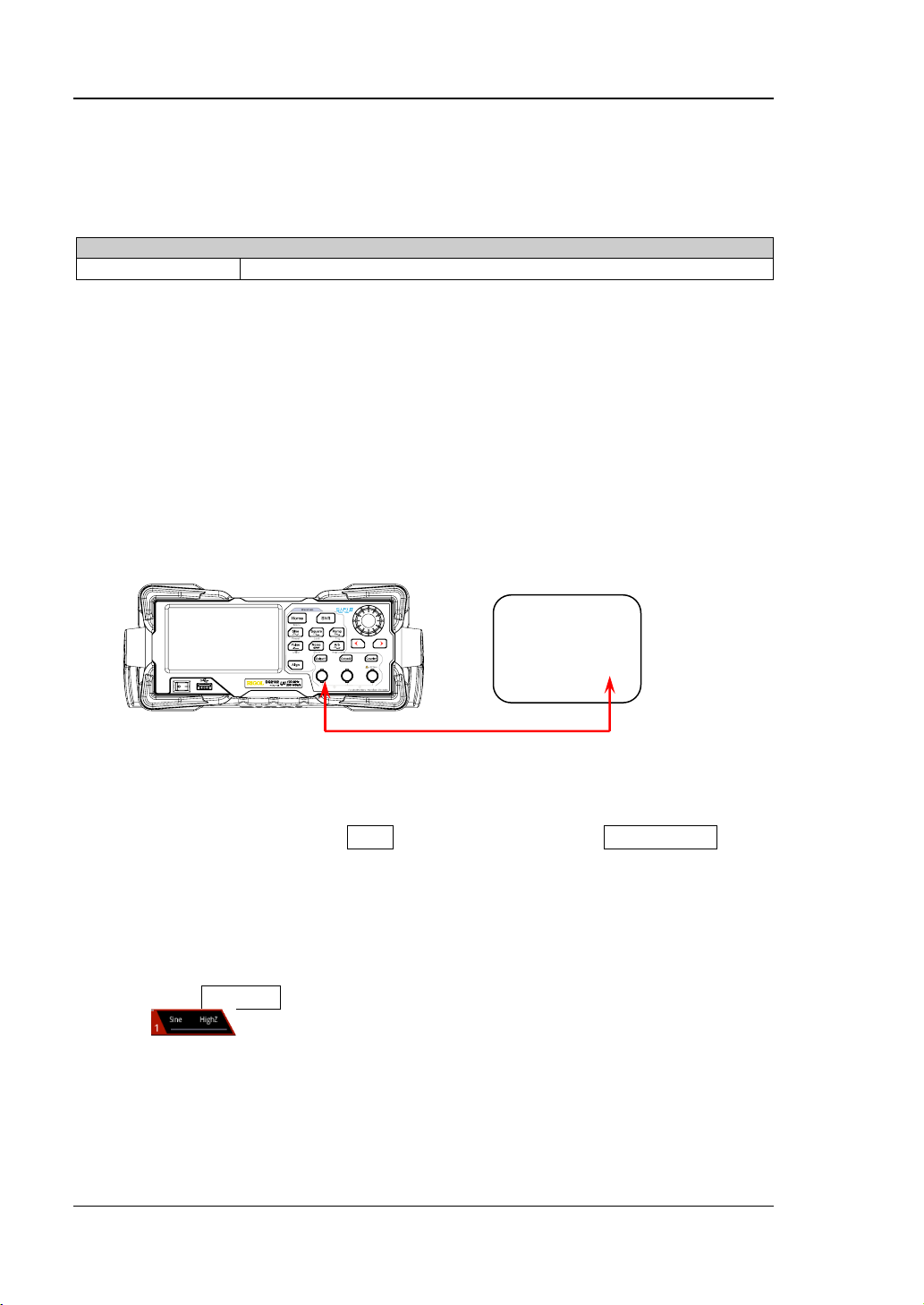
Test Procedures
1. Make sure that the environment temperature is between 18℃ and 28℃ and
DG2000 has been warmed up for at least 30 minutes. Connect the channel
output terminal (take CH1 as an example; the test method is also ap plicable to
CH2) of DG2000 with the signal input terminal of the frequency counter using a
dual-BNC cable as shown in Figure 2-1.
DG2000 Series Frequency Counter
◎
Figure 2-1 Connect DG2000 and the Frequency Counter
2. Turn on the frequency counter and set its output impedance to 1MΩ.
3. Turn on DG2000. When the Shift key is illuminated, press Sine/Preset and
tap the Def icon, then a dialog box is displayed, tap "Apply" to restore DG2000
to the factory settin g.
4. Set DG2000:
a) Set the output waveform of CH1 to a sine waveform with 1MHz frequency
and 1Vpp amplitude.
b) Press Output1 or tap the channel output configuration status bar
to turn on the output of CH1 in the channel setting interface.
5. Record the reading of the frequency counter and judge whether the reading is
between 0.999 998 999 999 999 99MHz and 1.000 001 000 000 000 01MHz.
6. Set CH1 of DG2000 to output square, ramp and pulse waveforms (the
frequencies are 1MHz and the amplitudes are 1Vpp) respectively. Record the
DG2000 Performance Verification Guide
Page 15
Chapter 2 Performance Verification Test RIGOL
2-3
Setting
Value
Measurement
Value
readings of the frequenc y counter respectively and judge whether the readings
are between 0.999 998 999 999 999 99MHz and 1.000 001 000 000 000 01MHz.
7. Repeat steps 1 to 6 to test the frequency accuracy of CH2 and record the test
results.
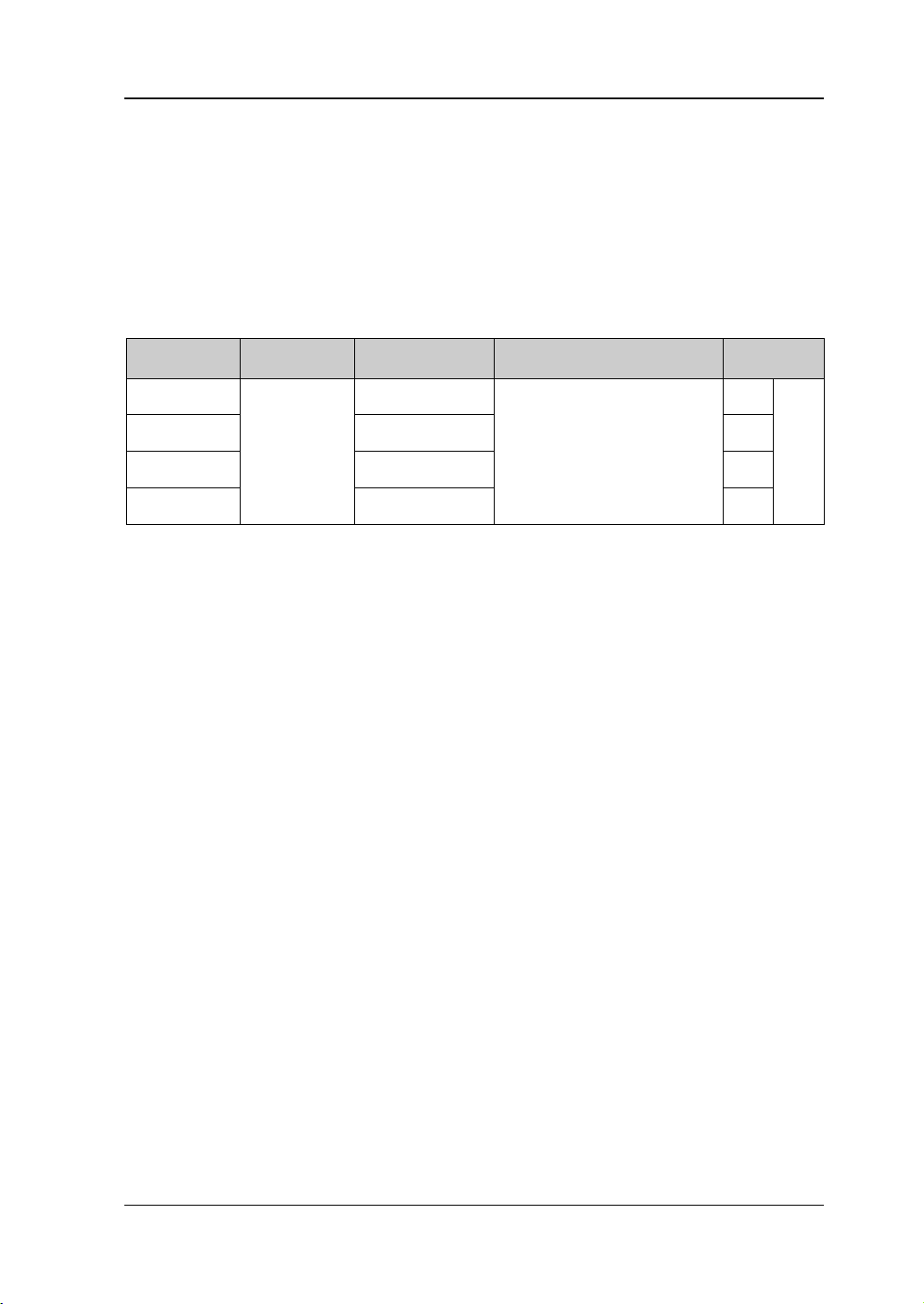
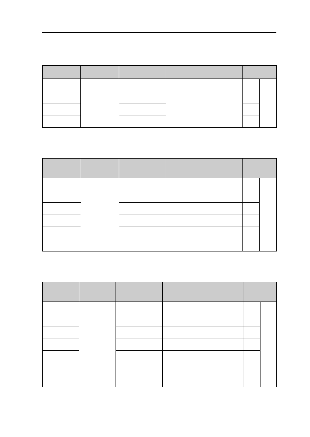
Test Record Form
Waveform
Sine
Square
Ramp
Pulse
Frequency:
1MHz
Amplitude:
1Vpp
Specification Pass/Fail
0.999 998 999 999 999
99MHz to 1.000 001 000 000
000 01MHz
DG2000 Performance Verification Guide
Page 16

RIGOL Chapter 2 Performance Verification Test
2-4
Output Characteristic
Amplitude (into 50Ω)
Typical (1kHz Sine, 0V Offset, >10mVpp, Auto)
±(1% of setting value) ±5mV
AC Amplitude Accuracy Test
Specification
Accuracy
Test Procedures
1. Make sure that the environment temperatu re is between 18℃ and 28℃ and
DG2000 has been warmed up for at least 30 minutes. Connect the 50Ω load to
the channel output terminal (take CH1 as an example; the test method is also
applicable to CH2) of DG2000; connect the 50Ω lo ad and the voltage input
terminals of the digital multimeter using a BNC-Dual banana plug conne cting
cable as shown in Figure 2-2.
DG2000 Series Digital Multimeter
◎ ◎
◎ ◎
◎
50Ω Load
Figure 2-2 Connect DG2000 and the Digital Multimeter via a 50Ω Load
2. Turn on the multimeter, select the ACV measurement f unction and set the rang e
to “Auto”.
3. Turn on DG2000. When the Shift key is illuminated, press Sine/Preset and
tap the Def icon, then a dialog box is displayed, tap "Apply" to restore DG2000
to the factory setting.
4. Set DG2000:
a) Set the output impedance of CH1 to 50Ω. (Tap the channel output
conf iguration status bar
under the user interface to enter the
channel setting interface. Tap the OutputSet HighZ to select "Off". Tap
the Impedance menu label, and set the impedanc e to 5 0Ω.)
b) Set the output waveform of CH1 to a sine waveform with 1kHz frequency,
20mVpp amplitude and 0V
offset.
dc
DG2000 Performance Verification Guide
Page 17
Chapter 2 Performance Verification Test RIGOL
2-5
Amplitude
(Vpp)
rms22pp VV =
Amplitude
Value
c) Press Output1 or tap the channel output configuration status bar
to turn on the output of CH1 in the channel setting interface.
5. Record the reading of the multimeter and judge whether it is within the
specif ication ("Amplitude Output Value (Vrms)" in Table 2-1) range.
6. Keep the out put i mpe da n ce of CH1 o f DG2000 at 50Ω and the output wave form
of CH1 as a sine waveform with 1kHz frequency and 0V
offset. Set the output
dc
amplitude of CH1 to 100mVpp, 500mVpp, 1Vpp, 5Vpp and 10Vpp respectively.
Record the readings of the multimeter respectively and judge whether the
readings are within the specification (“Amplitude Output Value (Vrms)” in Table
2-1) range.
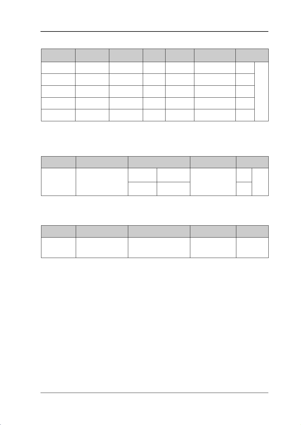
Table 2-1 Amp litude output values (Vrms) of AC amplitude accuracy t es t
Setting
Value
20mVpp ±5.2mVpp 14.8mVpp to 25.2mVpp 5.2mVrms to 8.9mVrms
100mVpp ±6mVpp 94mVpp to 106mVpp 33.2mVrms to 37.5mVrms
500mVpp ±10mVpp 490mVpp to 510mVpp 173.3mVrms to 180.3mVrms
1Vpp ±15mVpp 0.985Vpp to 1.015Vpp 348.3mVrms to 358.9mVrms
5Vpp ±55mVpp 4.945Vpp to 5.055Vpp 1.75Vrms to 1.7875Vrms
10Vpp ±105mVpp 9.895Vpp to 10.105Vpp 3.5Vrms to 3.5732Vrms
[1]
Note
: "Allowed Error" is calculated from the specification "±(1% of setting value) ±5mVpp".
[2]
Note
: "Amplitude Output Value (Vrms)" is calculated from "Amplitude Output Value (Vpp)".
The conversion relation between Vrms and Vpp is
Allowed
Error (Vpp)
Amplitude Output
[1]
Value (Vpp)
Amplitude Output Value
(Vrms)
[2]
.
7. Repeat Step 1-6 to test the AC amplitude accuracy of CH2 and record the test
results.
Test Record Form
Setting
20mVpp
Setting
Measurement
Value
5.2mVrms to 8.9mVrms
Specification Pass/Fail
100mVpp 33.2mVrms to 37.5mVrms
500mVpp 173.3mVrms to 180.3mVrms
1Vpp 348.3mVrms to 358.9mVrms
5Vpp 1.75Vrms to 1.7875Vrms
10Vpp 3.5Vrms to 3.5732Vrms
DG2000 Performance Verification Guide
Frequency:
1kHz
Offset: 0V
Impedance:
50Ω
dc
Page 18
RIGOL Chapter 2 Performance Verification Test
2-6
Output Characteristic
Offset (into 50Ω)
Accuracy
±(1% of setting value + 5mV + 1% of amplitude)
DC Offset Accuracy Test
Specification
Test Procedures
1. Make sure that the environment temperatu re is between 18℃ and 28℃ and
DG2000 has been warmed up for at least 30 minutes. Connect the 50Ω load to
the channel output terminal ( take CH1 as an example; the test method is also
applicable to CH2) of DG2000; connect the 50Ω lo ad and the voltage input
terminals of the digital multimeter using a BNC-Dual banana plug connecting
cable as shown in Figure 2-2.
2. T urn on the multimeter, select the DCV measurement function and set the range
to "20V".
3. Turn on DG2000. When the Shift key is illuminated, press Sine/Preset and
tap the Def icon, then a dialog box is displayed, tap "Apply" to restore DG2000
to the factory setting.
4. Set DG2000:
a) Set the output impedance of CH1 to 50Ω. (Tap the channel output
conf iguration status bar
channel setting interface. Tap the OutputSet HighZ to select "Off". Tap
the Impedance menu label, and set the impedanc e to 5 0Ω.)
b) Set the output waveform of CH1 to a sine waveform with 1kHz frequency,
5Vpp amplitude and 0V
offset.
dc
c) Press Output1 or tap the channel output configuration status bar
under the user interface to enter the
to turn on the output of CH1 in the channel setting interface.
5. Record the reading of the multimeter and judge whether it is within the
specif ication ("Offset" in Table 2-2) range.
6. Keep the out put i mpe da n ce of CH1 o f DG2000 at 50Ω and the output wave form
of CH1 as a sine waveform with 1kHz frequency and 5Vpp amplitude. Set the
offset of th e out put wa vef orm of C H1 t o -2.5V
and 2.5V
respectively. Record the readings of the multimeter respectively and
dc
judge whether the readings are within the specification ("Offset" in Table 2-2)
range.
, -1Vdc, -500mVdc, 500mVdc, 1Vdc
dc
DG2000 Performance Verification Guide
Page 19

Chapter 2 Performance Verification Test RIGOL
2-7
Offset Setting
Value
Amplitude
Setting Value
Offset
Value
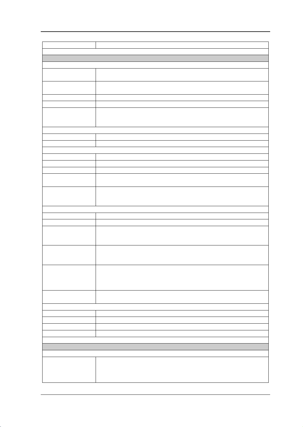
Table 2-2 Offset limits of DC offset accuracy test
Allowed Error
[1]
Offset
[2]
-2.5Vdc
±0.080Vdc -2.580Vdc to -2.420Vdc
-1Vdc ±0.065Vdc -1.065Vdc to -0.935Vdc
-500mVdc ±0.060Vdc -0.560Vdc to -0.440Vdc
0Vdc ±0.055Vdc -0.055Vdc to 0.055Vdc
5Vpp
500mVdc ±0.060Vdc 0.440Vdc to 0.560Vdc
1Vdc ±0.065Vdc 0.935Vdc to 1.065Vdc
2.5Vdc ±0.080Vdc 2.420Vdc to 2.580Vdc
[1]
Note
: “Allowed Err or ” is calculated from the specification “± (1% of setting value + 5 mV + 1% of
amplitude)”.
[2]
Note
: Offset = offset setting value ± allowed error.
7. Repeat Step1-6 to test the DC offset accuracy of CH2 and record the test results.
Test Record Form
Setting
-2.5Vdc
Setting
Measurement
Value
Specification Pass/Fail
-2.580Vdc to -2.420Vdc
-1Vdc -1.065Vdc to -0.935Vdc
Frequency:
-500mVdc -0.560Vdc to -0.440Vdc
0Vdc -0.055Vdc to 0.055Vdc
500mVdc 0.440Vdc to 0.560Vdc
1kHz
Amplitude:
5Vpp
Impedance:
50Ω
1Vdc 0.935Vdc to 1.065Vdc
2.5Vdc 2.420Vdc to 2.580Vdc
DG2000 Performance Verification Guide
Page 20

RIGOL Chapter 2 Performance Verification Test
2-8
Typical (Sine, 1 Vpp)
>40 MHz: ±1 dB
]1
/)/[(10
ref
2
reading10
mWRVLogdBm ×=
AC Flatness Test
Specification
Output Characteristic
≤5 MHz: ±0.1 dB
Flatness
Test Procedures
1. Make sure that the environment temperatu re is between 18℃ and 28℃ and
DG2000 has been warmed up for at least 30 minutes. Connect the 50Ω load to
the channel output terminal ( take CH1 as an example; the test method is also
applicable to CH2) of DG2000; connect the 50Ω lo ad and the voltage input
terminals of the digital multimeter using a BNC-Dual banana plug connecting
cable as shown in Figure 2-2.
2. Turn on DG2000. When the Shift key is illuminated, press Sine/Preset and
tap the Def icon, then a dialog box is displayed, tap "Apply" to restore DG2000
to the factory setting.
3. Set DG2000:
a) Set the output impedance of CH1 to 50Ω. (Tap the channel output
conf iguration status bar
channel setting interface. Tap the OutputSet HighZ to select "Off". Tap
the Impedance menu label, and set the impedanc e to 5 0Ω.)
b) Set the output waveform of CH1 to a sine waveform with 1kHz frequency
and 1Vpp amplitude.
c) Press Output1 or tap the channel output configuration status bar
≤15 MHz: ±0.2 dB
≤25 MHz: ±0.3 dB
≤40MHz: ±0.5 dB
under the user interface to enter the
4. Turn on the multimeter and select the ACV measurement function. Turn on the
dBm operation function and set the reference resistance to 50Ω. Rea d th e
measurement value and take it as the reference power (P
Tip:
In this step, if the dBm operation function is not turned on, you can also
calculate the reference power using the formula
to turn on the output of CH1 in the channel setting interface.
).
ref
according to the measurement value of
DG2000 Performance Verification Guide
Page 21

Chapter 2 Performance Verification Test RIGOL
2-9
reading
V
the multimeter.
Wherein,
is the measurement value of the multimeter.
5. Calibrate the power meter:
a) Connect the power sensor to the input ter minal and [POWER REF]
terminal of the power meter respectively.
b) Press Zero/Cal Zero Cal. Turn on power reference after t he
calibration finishes and observe whether the measurement value of the
power meter is a 0dBm, 50MHz signal.
c) Turn off power reference.
6. Disconnect DG2000 and the multimeter. Connect the power sensor and the
channel output terminal (take CH1 as an example; the test method is also
applicable t o CH 2) of DG2000 using a BNC (f)-N (m) adaptor, as shown in Figure
2-3.
DG2000 Series Power Meter
◎
Figure 2-3 Connect DG2000 a nd the Power Meter
7. Keep the output impe dance of CH1 of DG2000 at 50Ω. Set the output waveform
of CH1 as a sine waveform with 5MHz frequency and 1Vpp amplitu d e. S et the
frequency fa cto r of the po wer me ter to 5MHz, re cord the measurement value o f
the power meter and judge whether “measurement value-P
” is between
ref
-0.1dB and +0.1dB.
8. Keep the output impe dance of CH1 of DG2000 at 50Ω. Set the output waveform
of CH1 as a si ne waveform with 10MHz frequency and 1Vpp amplitude. Set the
frequency factor of the power meter to 10MHz, record the measurement value
of the power meter and judge whether “measur ement value-P
” is between
ref
-0.2dB and +0.2dB.
9. Keep the output impe dance of CH1 of DG2000 at 50Ω. Set the output waveform
of CH1 as a sine waveform with 15MHz frequency and 1Vpp amplitude. Set the
frequency factor of the power meter to 15MHz, record the me asurement va lue
of the power meter and judge whether “measurement value-P
” is between
ref
-0.2dB and +0.2dB.
DG2000 Performance Verification Guide
Page 22

RIGOL Chapter 2 Performance Verification Test
2-10
10. K ee p the output impe dance of CH 1 of DG2000 at 50Ω. Set the output waveform
of CH1 as a sine waveform with 20MHz frequency and 1Vpp amplitude. Set the
frequency factor of the power meter to 20MHz, recor d the measurement value
of the power meter and judge whether "measurement value-P
" is between
ref
-0.3dB and +0.3dB.
11. K ee p the output impe dance of CH 1 of DG2000 at 50Ω. Set the output waveform
of CH1 as a si ne waveform with 25MHz frequency and 1Vpp amplitude. Set the
frequency factor of the power meter to 25MHz, record the measurement value
of the power meter and judge whether "measurement value-P
" is between
ref
-0.3dB and +0.3dB.
12. K ee p the output impe dance of CH 1 of DG2000 at 50Ω. Set the output waveform
of CH1 as a si ne waveform with 30MHz frequency and 1Vpp amplitude. Set the
frequency factor of the power meter to 30MHz, record the measurement value
of the power meter and judge whether "measurement value-P
" is between
ref
-0.5dB and +0.5dB.
13. K ee p the output impe dance of CH 1 of DG2000 at 50Ω. Set the output waveform
of CH1 as a si ne waveform with 40MHz frequency and 1Vpp amplitude. Set the
frequency factor of the power meter to 40MHz, record the measurement value
of the power meter and judge whether "measurem ent value-P
" is between
ref
-0.5dB and +0.5dB.
14. K ee p the output impe dance of CH 1 of DG2000 at 50Ω. Set the output waveform
of CH1 as a si ne waveform with 50MHz frequency and 1Vpp amplitude. Set the
frequency factor of the power meter to 50MHz, record the measurement va lue
of the power meter and judge whether "measurement value-P
" is between
ref
-1dB and +1dB.
15. Repeat Step 1-14 to test the AC flatness of CH2 and record the test results.
DG2000 Performance Verification Guide
Page 23

Chapter 2 Performance Verification Test RIGOL
2-11
Frequency
Value
Test Record Form
Setting
5MHz
Setting
Measurement
Value
±0.1dB
Calculation
[1]
Result
Specification Pass/Fail
10MHz ±0.2dB
15MHz ±0.2dB
Amplitude:
20MHz ±0.3dB
25MHz ±0.3dB
1Vpp
Impedance:
50Ω
30MHz ±0.5dB
40MHz ±0.5dB
50MHz
[1]
Note
: Calculation result = Measurem en t value - P
±1dB
ref.
DG2000 Performance Verification Guide
Page 24

RIGOL Chapter 2 Performance Verification Test
2-12
Sine Wave Spectrum Purity
Typical
[1]
>40 MHz: <-35 dBc
Harmonic Distortion Test
Specification
DC to 10 MHz (included): <-55 dBc
Harmonic Distortion
[1]
Note
: 0 dBm output, DC offset 0, impedance 50 Ω.
Test Procedures
1. Make sure that the environment temperature is between 18℃ and 28℃ and
DG2000 has been warmed up for at least 30 minutes. Connect the channel
output terminal (take CH1 as an example; the test method is also applic ab le to
CH2) of DG2000 with the signal input terminal of the spectrum analyzer us ing a
dual-BNC connecting cable and N-BNC adaptor as shown in Figure 2-4.
DG2000 Series Spectrum Analyzer
10 MHz to 20 MHz (included): < -50 dBc
20 MHz to 40 MHz (included) : <-40 dBc
◎
Figure 2-4 Connect DG2000 and the Spectrum Analyzer
2. Turn on DG2000. When the Shift key is illuminated, press Sine/Preset and
tap the Def icon, then a dialog box is displayed, tap "Apply" to restore DG2000
to the factory setting.
3. Set DG2000:
a) Set the outp ut impedance of CH1 to 50Ω. (Tap the channel output
conf iguration status bar
under the user interface to enter the
channel setting interface. Tap the OutputSet HighZ to select "Off". Tap
the Impedance menu label, and set the impedanc e to 5 0Ω.)
b) Set the outpu t wav eform of CH 1 to a sine wa vefor m with 10 MHz frequen cy,
0dBm amplitude and 0V
offset.
dc
c) Press Output1 or tap the channel output configuration status bar
to turn on the output of CH1 in the channel setting interface.
DG2000 Performance Verification Guide
Page 25

Chapter 2 Performance Verification Test RIGOL
2-13
4. Turn on and set the sp e ctrum analyzer:
a) Set the reference level to 10dBm and input attenuation to 20dB.
b) Set the start frequency to 5MHz and stop frequency to 30MHz.
c) Set the resolution bandwidth to 3kHz.
5. Use the marker function to make measurements a n d record the measureme nt
values of the base waveform and 2
nd
order harmonic. Calculate
[2]
the harmonic
distortion and judge whether it is less than -55dBc.
6. Keep the output impe dance of CH1 of DG2000 at 50Ω. Set the output waveform
of CH1 as a sine waveform with 20MHz frequency, 0dBm amplitude and 0V
dc
offset.
7. Keep the reference level, input attenuation and resolution bandwidth of the
spectrum analyzer as 10dBm, 20dB and 3kHz respectively. Set its start
frequency to 10MHz and stop frequency to 60MHz.
8. Use the marker function to make measurements and rec o r d the measurement
values of the base waveform a nd 2
nd
order harmonic. Calculate
[2]
the harmonic
distortion and judge whether it is less than -50dBc.
9. Keep the output impe dance of CH1 of DG2000 at 50Ω. Set the output waveform
of CH1 as a sine waveform with 40MHz frequency, 0dBm amplitude and 0V
dc
offset.
10. Keep the input attenuation, reference level and resolution bandwidth of the
spectrum analyzer as 20dB, 10dBm and 3kHz respectively. Set its start
frequency to 30MH z and stop frequency to 130MHz.
11. Use the marker function to make measurements and reco r d the measurement
values of the base waveform a nd 2
nd
order harmonic. Calculate
[2]
the harmonic
distortion and judge whether it is less than -40dBc.
12. Keep the output impe dance of CH 1 of DG2000 at 50Ω. Set the output waveform
of CH1 as a sine waveform with 60MHz frequency, 0dBm amplitude and 0V
dc
offset.
13. Keep the input attenuation, reference level and resolution bandwidth of the
spectrum analyzer as 20dB, 10dBm and 3kHz respectively. Set its start
frequency to 50MH z and stop frequency to 150MHz.
14. Use the marker function to make measurements and recor d the measurement
values of the base waveform a nd 2
nd
order harmonic. Calculate
[2]
the harmonic
distortion and judge whether it is less than -35dBc.
15. Repeat Step 1-14 to test the harmonic distortion of CH2 and record the tes t
DG2000 Performance Verification Guide
Page 26
RIGOL Chapter 2 Performance Verification Test
2-14
Frequency
Value
2nd order
harmonic:
2nd order
harmonic:
2nd order
harmonic:
2nd order
harmonic:
results.
[2]
Note
: 2nd order harmonic distortion = 2nd order harmonic measurement value – base waveform
measurement value
For example, when the output waveform frequency of the channel is 10MHz, if the base
waveform measurement value is 0.8dBm and the 2
is -56.2dBm, the 2
nd
order harmonic distortion = (-56.2) -0.8=-57dBc<-55dBc and the
nd
order harmonic measurement value
test result fulfills the specification requirement.
Test Record Form
Setting
Setting
Measurement
Value
Calculation
[3]
Result
Specification Pass/Fail
Base waveform:
10MHz
<-55dBc
Base waveform:
20MHz
Waveform:
Sine
<-50dBc
Amplitude:
40MHz
0dBm
Offset: 0V
Base waveform:
dc
<-40dBc
Base waveform:
60MHz
[3]
Note
: Calculation result = 2th order harmonic measurement value - base waveform measurement value.
<-35dBc
DG2000 Performance Verification Guide
Page 27
Chapter 2 Performance Verification Test RIGOL
2-15
Sine Wave Spectrum Purity
Typical
[1]
>10 MHz: <-60 dBc + 6 dB/octave
Spurious Signal Test
Specification
Spurious signal
(non-harmonic)
[1]
Note
: 0 dBm output, DC offset 0, impedance 50 Ω.
[1]
Note
: 6 dBc/octave means that when the frequency doubles, the specification increases by 6 dBc. For example,
when the output frequency of DG2000 is 10MHz, the specification is <-60dBc and when the output frequency
is 30MHz, the specif ic a t io n is <-60dBc+2×6dBc, namely <-48dBc.
≤10 MHz: <-60 dBc
[2]
Test Procedures
1. Make sure that the environment temperatu re is between 18℃ and 28℃ and
DG2000 has been warmed up for a t least 30 minutes. Connect the channel
output terminal (take CH1 as an example; the test method is also applic ab le to
CH2) of DG2000 with the RF input terminal of the spectrum analy zer using a
dual-BNC cable and N-BNC adaptor as shown in Figure 2-4.
2. Turn on DG2000. When the Shift key is illuminated, press Sine/Preset and
tap the Def icon, then a dialog box is displayed, tap "Apply" to restore DG2000
to the factory setting.
3. Set DG2000:
a) Set the output impedance of CH1 to 50Ω. (Tap the channel output
conf iguration status bar
channel setting interface. Tap the OutputSet HighZ to select "Off". Tap
the Impedance menu label, and set the impedanc e to 5 0Ω.)
b) Set the output waveform of CH1 to a sine waveform with 5MHz frequency,
0dBm amplitude and 0V
offset.
dc
d) Press Output1 or tap the channel output configuration status bar
under the user interface to enter the
4. Turn on and set the spectrum analyzer :
a) Set the reference level to 10dBm and input attenuation to 20dB.
b) Set the start frequency to 0Hz and stop frequency to 30MHz.
c) Set the resolution bandwidth to 1kHz.
d) Set the peak offset to 3dB.
e) Set the sweep mode to single.
5. After the spectrum analyzer finishes a sweep, use Peak and the marker
function to measure the maximum spurious signal (except harmonics) and
DG2000 Performance Verification Guide
to turn on the output of CH1 in the channel setting interface.
Page 28

RIGOL Chapter 2 Performance Verification Test
2-16
record the measurement result as A. Calcul ate the non-harmonic sp urious signal
(A-0dBm) and judge whether it is within the specification range.
6. Keep the output impedance of CH1 of DG2000 at 50Ω. Set the output waveform
of CH1 as a si ne waveform with 10MHz frequency, 0dBm amplitude and 0V
dc
offset.
7. Keep the reference level, input attenuation, resolution bandwidth, peak offset
and sweep mode of the spectrum analyzer as 10dBm, 20dB, 1kHz, 3dB and
single respectively. Set its start frequency to 0Hz and stop frequency to 50MHz.
8. Press Sweep/Trig Single to perform a sweep.
9. After the spectrum analyzer finishes a sweep, use Peak and the marker
function to measure the maximum spurious signal (except harmonics) and
record the measurement result as A. Calcul ate the non-harmonic sp urious signal
(A-0dBm) and judge whether it is within the specification range.
10. K ee p the output impe dance of CH 1 of DG2000 at 50Ω. Set the output waveform
of CH1 as a si ne waveform with 20MHz frequency, 0dBm amplitude and 0V
dc
offset.
11. Keep the reference level, input attenuation, resolution bandwidth, peak offset
and sweep mode of the spectrum analyzer as 10dBm, 20dB, 1kHz, 3dB and
single respectively. Set its start fre quency to 0Hz and stop frequency to 100MHz.
12. Repeat Step 8 and 9.
13. K ee p the output impe dance of CH 1 of DG2000 at 50Ω. Set the output waveform
of CH1 as a si ne waveform with 30MHz frequency, 0dBm amplitude and 0V
dc
offset.
14. Keep the reference level, input attenuation, resolution bandwidth, peak offset
and sweep mode of the spectrum analyzer as 10dBm, 20dB, 1kHz, 3dB and
single respectively. Set its start fre quency to 0Hz and stop frequency to 150MHz.
15. Repeat Step 8 and 9.
16. K ee p the output impe dance of CH 1 of DG2000 at 50Ω. Set the output waveform
of CH1 as a sine waveform with 60MHz frequency, 0dBm amplitude and 0V
dc
offset.
17. Keep the reference level, input attenuation, resolution bandwidth, peak offset
and sweep mode of the spectrum analyzer as 10dBm, 20dB, 1kHz, 3dB and
single respectively. Set its start fre quency to 0Hz and stop frequency to 300MHz.
DG2000 Performance Verification Guide
Page 29
Chapter 2 Performance Verification Test RIGOL
2-17
Output
Frequency
Start
Frequency
Stop
Frequency
18. Repeat Step 8 and 9.
19. Repeat Step 1-18 to test the spurious signal (non-harmonic) of CH2 and record
the test results.
Test Record Form
A A-0dBm Specification Pass/Fail
5MHz 0Hz 30MHz <-60dBc
10MHz 0Hz 50MHz <-60dBc
20MHz 0Hz 100MHz <-54dBc
30MHz 0Hz 150MHz <-48dBc
60MHz
0Hz 300MHz <-30dBc
DG2000 Performance Verification Guide
Page 30

RIGOL Chapter 2 Performance Verification Test
2-18
Typical (1 Vpp, 1 kHz)
≤9 ns
Rise/Fall Time Test
Specification
Signal Characteristic
Square
Rise/Fall Time
Test Procedures
1. Make sure that the environment temperatu re is between 18℃ and 28℃ and
DG2000 has been warmed up for at least 30 minutes. Connect the channel
output terminal (take CH1 as an example; the test method is also ap p licable to
CH2) of DG2000 with the signal input terminal o f the oscilloscope using a
dual-BNC connecting cable as shown in Figure 2-5.
DG2000 Series Oscilloscope
◎
Figure 2-5 Connect DG2000 and the Oscilloscope
2. Turn on DG2000. When the Shift key is illuminated, press Sine/Preset and
tap the Def icon, then a dialog box is displayed, tap "Apply" to restore DG2000
to the factory setting.
3. Set DG2000:
a) Set the output impedance of CH1 to 50Ω. (Tap the channel output
conf iguration status bar
under the user interface to enter the
channel setting interface. Tap the OutputSet HighZ to select "Off". Tap
the Impedance menu label, and set the impedanc e to 50Ω.)
b) Set the output w av eform o f CH1 to a square waveform with 1kHz frequency,
1Vpp amplitude and 0V
offset.
dc
c) Press Output1 or tap the channel output configuration status bar
to turn on the output of CH1 in t he channel setting interface.
4. Turn on and set the oscilloscope:
a) Set the ver tica l scale to 200mV/div.
DG2000 Performance Verification Guide
Page 31

Chapter 2 Performance Verification Test RIGOL
2-19
Measurement
Value
b) Set the horizontal time base to 1us.
c) Adjust the trigger level to a proper value.
d) Set the input impedance to 50Ω.
e) Turn on the rise time and fall time measurement functions.
5. Set the edge type of the oscilloscope to rising edge, record the measur ement
result of the rise time and judge whether it is within the specification range.
6. Set the edge type of the oscilloscope to falling edge, record the measurement
result of the fall time and judge whether it is within the specification range.
7. Repeat Step 1-6 to test the rise/fall time of CH2 and record the measurement
results.
Test Record Form
Waveform Setting
Frequency: 1kHz
Square
Amplitude: 1Vpp
Offset: 0Vdc
Rise Time
Fall Time
Specification Pass/Fail
Typical (1 Vpp, 1
kHz)
≤9 ns
DG2000 Performance Verification Guide
Page 32

RIGOL Chapter 2 Performance Verification Test
2-20
Typical (100kHz, 1Vpp)
≤5%
Overshoot Test
Specification
Signal Characteristic
Square
Overshoot
Test Procedures
1. Make sure that the environment temperature is between 18℃ and 28℃ and
DG2000 has been warmed up for at least 30 minutes. Connect the channel
output terminal (take CH1 as an example; the test method is also app licable to
CH2) of DG2000 with the signal input terminal o f the oscilloscope using a
dual-BNC conne cting cable as s hown in Figure 2-5.
2. Turn on DG2000. When the Shift key is illuminated, press Sine/Preset and
tap the Def icon, then a dialog box is displayed, tap "Apply" to restore DG2000
to the factory setting.
3. Set DG2000:
a) Set the output impedance of CH1 to 50Ω. (Tap the channel output
conf iguration status bar
channel setting interface. Tap the OutputSet HighZ to select "Off". Tap
the Impedance menu label, and set the impedanc e to 5 0Ω.)
b) Set the output waveform of CH1 to a square waveform with 100kHz
frequency, 1Vpp amplitude and 0V
c) Press Output1 or tap the channel output configuration status bar
under the user interface to enter the
offset.
dc
4. Turn on and set the oscilloscope:
a) Set the inpu t impe dance to 50Ω.
b) Set the vertical scale to 200mV/div.
c) Set the horizontal time base to 50ns.
d) Adjust the trigger level to a proper value.
e) Turn on the overshoot measurement function.
5. Record the overshoot measurement value and judge whether it is within the
specification range.
6. Repeat Step 1-5 to test the overshoot of CH2 and rec o rd the meas urement
result.
to turn on the output of CH1 in the channel setting interface.
DG2000 Performance Verification Guide
Page 33

Chapter 2 Performance Verification Test RIGOL
2-21
dc
Test Record Form
Waveform Setting Measurement Value Specification Pass/Fail
Square
Frequency: 100kHz
Amplitude: 1Vpp
Offset: 0V
Typical (100kHz,
1Vpp)
≤5%
DG2000 Performance Verification Guide
Page 34

Page 35

Appendix RIGOL
1
Model:
Tested by:
Test Date:
Setting
Value
Measurement
Value
Amplitude
Value
Appendix
Appendix A: Test Result Record Form
RIGOL DG2000 Series Function/Arbitrary Waveform Generator
Performance Verification Test Record Form
Channel: CH1
Frequency Accuracy Test
Waveform
Sine
Square
Ramp
Pulse
Frequency:
1MHz
Amplitude:
1Vpp
Specification Pass/Fail
0.999 998 999 999 999
99MHz to 1.000 001 000 000
000 01MHz
AC Amplitude Accuracy Test
Setting
20mVpp
100mVpp 33.2mVrms to 37.5mVrms
500mVpp 173.3mVrms to 180.3mVrms
1Vpp 348.3mVrms to 358.9mVrms
5Vpp 1.75Vrms to 1.7875Vrms
10Vpp 3.5Vrms to 3.5732Vrms
Setting
Frequency:
1kHz
Offset: 0V
Impedance:
50Ω
Measurement
Value
5.2mVrms to 8.9mVrms
dc
Specification Pass/Fail
DG2000 Performance Verification Guide
Page 36

RIGOL Appendix
2
Offset
Value
Frequency
Value
DC Offset Accuracy Test
Setting
-2.5Vdc
-1Vdc -1.065Vdc to -0.935Vdc
-500mVdc -0.560Vdc to -0.440Vdc
0Vdc -0.055Vdc to 0.055Vdc
500mVdc 0.440Vdc to 0.560Vdc
1Vdc 0.935Vdc to 1.065Vdc
2.5Vdc 2.420Vdc to 2.580Vdc
Setting
Frequency:
1kHz
Amplitude:
5Vpp
Impedance:
50Ω
Measurement
Value
-2.580Vdc to -2.420Vdc
Specification Pass/Fail
AC Flatness Test
Setting
5MHz
10MHz ±0.2dB
Setting
Measurement
Value
±0.1dB
Calculation
[1]
Result
Specification Pass/Fail
15MHz ±0.2dB
20MHz ±0.3dB
25MHz ±0.3dB
30MHz ±0.5dB
40MHz ±0.5dB
50MHz
[1]
Note
: Calculation result = Measurement value - P
Amplitude:
1Vpp
Impedance:
50Ω
±1dB
.
ref
DG2000 Performance Verification Guide
Page 37

Appendix RIGOL
3
Frequency
Value
2nd order
harmonic:
2nd order
harmonic:
2nd order
harmonic:
2nd order
harmonic:
Output
Frequency
Start
Frequency
Stop
Frequency
Harmonic Distortion Test
Setting
Setting
Measurement
Value
Calculation
[1]
Result
Specification Pass/Fail
Base waveform:
10MHz
<-55dBc
Base waveform:
20MHz
Waveform:
Sine
<-50dBc
Amplitude:
0dBm
40MHz
[2]
60MHz
[1]
Note
: Calculation result = 2th order harmonic measurement value - base waveform measurement value.
[2]
Note
: Only applicable to DG2102 and DG2072.
Offset: 0Vdc
Base waveform:
<-40dBc
Base waveform:
<-35dBc
Spurious Signal Test
A A-0dBm Specification Pass/Fail
5MHz 0Hz 30MHz <-60dBc
10MHz 0Hz 50MHz <-60dBc
20MHz 0Hz 100MHz <-54dBc
30MHz 0Hz 150MHz <-48dBc
[1]
60MHz
[1]
Note
: Only applicable to DG2102 and DG2072.
0Hz 300MHz <-30dBc
Rise/Fall Time Test
Waveform Setting Measurement Value Specification Pass/Fail
Square
Frequency: 1kHz
Amplitude: 1Vpp
Offset: 0Vdc
Rise Time
Fall Time
Typical (1 Vpp, 1
kHz)
≤9 ns
DG2000 Performance Verification Guide
Page 38

RIGOL Appendix
4
dc
Overshoot Test
Waveform Setting Measurement Value Specification Pass/Fail
Square
Frequency: 100kHz
Amplitude: 1Vpp
Offset: 0V
Typical (100kHz,
1Vpp)
≤5%
DG2000 Performance Verification Guide
Page 39
Appendix RIGOL
5
Setting
Value
Measurement
Value
Amplitude
Value
Offset
Value
Channel: CH2
Frequency Accuracy Test
Waveform
Sine
Square
Ramp
Pulse
Frequency:
1MHz
Amplitude:
1Vpp
Specification Pass/Fail
0.999 998 999 999 999
99MHz to 1.000 001 000 000
000 01MHz
AC Amplitude Accuracy Test
Setting
20mVpp
100mVpp 33.2mVrms to 37.5mVrms
500mVpp 173.3mVrms to 180.3mVrms
1Vpp 348.3mVrms to 358.9mVrms
5Vpp 1.75Vrms to 1.7875Vrms
10Vpp 3.5Vrms to 3.5732Vrms
Setting
Frequency:
1kHz
Offset: 0V
Impedance:
50Ω
Measurement
Value
5.2mVrms to 8.9mVrms
dc
Specification Pass/Fail
DC Offset Accuracy Test
Setting
-2.5Vdc
-1Vdc -1.065Vdc to -0.935Vdc
-500mVdc -0.560Vdc to -0.440Vdc
0Vdc -0.055Vdc to 0.055Vdc
500mVdc 0.440Vdc to 0.560Vdc
1Vdc 0.935Vdc to 1.065Vdc
2.5Vdc 2.420Vdc to 2.580Vdc
DG2000 Performance Verification Guide
Setting
Frequency:
1kHz
Amplitude:
5Vpp
Impedance:
50Ω
Measurement
Value
-2.580Vdc to -2.420Vdc
Specification Pass/Fail
Page 40

RIGOL Appendix
6
Frequency
Value
Frequency
Value
2nd order
harmonic:
2nd order
harmonic:
2nd order
harmonic:
2nd order
harmonic:
AC Flatness Test
Setting
5MHz
Setting
Measurement
Value
±0.1dB
Calculation
[1]
Result
Specification Pass/Fail
10MHz ±0.2dB
15MHz ±0.2dB
Amplitude:
20MHz ±0.3dB
25MHz ±0.3dB
1Vpp
Impedance:
50Ω
30MHz ±0.5dB
40MHz ±0.5dB
50MHz
[1]
Note
: Calculation result = Measurement value - P
±1dB
.
ref
Harmonic Distortion Test
Setting
10MHz
Setting
Measurement
Value
Base waveform:
Calculation
[1]
Result
Specification Pass/Fail
<-55dBc
20MHz
Waveform:
Sine
<-50dBc
Amplitude:
Base waveform:
0dBm
40MHz
[2]
60MHz
[1]
Note
: Calculation result = 2th order harmonic measurement value - base waveform measurement value.
[2]
Note
: Only applicable to DG2102 and DG2072.
Offset: 0V
Base waveform:
dc
Base waveform:
<-40dBc
<-35dBc
DG2000 Performance Verification Guide
Page 41
Appendix RIGOL
7
Output
Frequency
Start
Frequency
Stop
Frequency
dc
Spurious Signal Test
A A-0dBm Specification Pass/Fail
5MHz 0Hz 30MHz <-60dBc
10MHz 0Hz 50MHz <-60dBc
20MHz 0Hz 100MHz <-54dBc
30MHz 0Hz 150MHz <-48dBc
[1]
60MHz
[1]
Note
: Only applicable to DG2102 and DG2072.
0Hz 300MHz <-30dBc
Rise/Fall Time Test
Waveform Setting Measurement Value Specification Pass/Fail
Square
Frequency: 1kHz
Amplitude: 1Vpp
Offset: 0V
dc
Rise Time
Fall Time
Typical (1 Vpp, 1
kHz)
≤9 ns
Overshoot Test
Waveform Setting Measurement Value Specification Pass/Fail
Square
Frequency: 100kHz
Amplitude: 1Vpp
Offset: 0V
Typical (100kHz,
1Vpp)
≤5%
DG2000 Performance Verification Guide
Page 42

RIGOL Appendix
8
Model
DG2052
DG2072
DG2102
Channel
2 2 2
Max. Frequency
50 MHz
70 MHz
100 MHz
Sample Rate
250 MSa/s
Waveform
Basic Waveforms
Sine, Square, Ramp, Pulse, Noise, DC, Dual-tone
Advanced
Waveforms
Built-in Arbitrary
Waveforms
160 types of waveforms, including Sinc, Exponential Rise, Exponential
Fall, ECG, Gauss, HaverSine, Lorentz, etc.
Frequency Characteristics
Sine
1 μHz to 50 MHz
1 μHz to 70 MHz
1 μHz to 100 MHz
Square
1 μHz to 15 MHz
1 μHz to 20 MHz
1 μHz to 25 MHz
Pulse
1 μHz to 15 MHz
1 μHz to 20 MHz
1 μHz to 25 MHz
Harmonic
1 μHz to 20 MHz
1 μHz to 20 MHz
1 μHz to 25 MHz
PRBS
2 kbps to 40 Mbps
2 kbps to 50 Mbps
2 kbps to 60 Mbps
Dual-tone
1 μHz to 20 MHz
1 μHz to 20 MHz
1 μHz to 20 MHz
baud rate range: 9600, 14400, 19200, 38400, 57600, 115200, 128000,
230400
Sequence
2 k to 60 MSa/s
Noise (-3 dB)
100 MHz bandwidth
Arbitrary Wavef orm
1 μHz to 15 MHz
1 μHz to 20 MHz
1 μHz to 20 MHz
Resolution
1 μHz
Sine Wave Spectrum Purity
Typical
[1]
>40 MHz: <-35 dBc
Total Harmonic
Distortion
Typical
[1]
>10 MHz: <-60 dBc + 6 dB/octave
Phase Noise
Typical (0 dBm, 10 kHz offset)
Appendix B: Performance Specifications
Unless otherwise specified, all the specifications can be guaranteed when the
following two conditions are met.
The signal generator is within the calibration period.
The signal generator has been running ceaselessly for over 30 minutes under
the sp ecif ied operati ng temperature (23℃±5℃).
All the specifications are guaranteed except the parameters marked with "Typical".
PRBS, RS232, Sequence
Ramp 1 μHz to 1.5 MHz 1 μHz to 1.5 MHz 1 μHz to 2 MHz
RS232
Accuracy
Harmonic Distortion
[1]
Spurious
(non-harmonic)
±(1 ppm of the setting value + 10 pHz), 18℃ to 28℃
DC to 10 MHz (included): <-55 dBc
10 MHz to 20 MHz (included): <-50 dBc
20 MHz to 40 MHz (included): <-40 dBc
<0.075% (10 Hz to 20 kHz)
≤10 MHz: <-60 dBc
DG2000 Performance Verification Guide
Page 43
Appendix RIGOL
9
10 MHz: <-105 dBc/Hz
Signal Characteristics
Square
Typical (1 Vpp, 1 kHz)
≤9 ns
Typical (100 kHz, 1 Vpp)
≤5%
Duty
0.01% to 99.99% (limited by the current frequency setting)
Non-symmetry
1% of the period + 4 ns
Typical (1 Vpp)
>5 MHz: 200 ps
Ramp
Linearity
≤1% of peak output (typical, 1 kHz, 1 VPP, 100% symmetry)
Symmetry
0% to 100%
Pulse
Pulse
16 ns to 1000 ks (limited by the current frequency setting)
Duty
0.001% to 99.999% (limited by the current frequency setting)
Rising/Falling Edge
≥8 ns (limited by the current frequency setting and pulse width setting)
Typical (1 Vpp, 1 kHz)
≤5%
Typical (1 Vpp)
>5 MHz: 200 ps
Arbitrary Waveform Sequence
Waveform Length
16 Mpts
Vertical Resolution
16 bits
Interpolation filter: 10 Sa/s to 60 MSa/s
Smooth filter: 2k Sa/s to 50 MSa/s
Interpolation f ilter: ≥8 ns
Smooth filter: 1.0/sample rate
Typical (1 Vpp)
Smooth filter: <5 ps
Typical (1 Vpp)
≤5%
Harmonic Output
Harmonic Order
≤8
Harmonic Type
Even Harmonic, Odd Harmonic, Order Harmonic, User
Harmonic Amplitude
The amplitude of each order of the harmonic can be set.
Harmonic Phase
The phase of each order of harmonic can be set.
Output Characteristics
Amplitude (into 50 Ω)
≤10 MHz: 1.0 mVpp to 10 Vpp
>60 MHz: 1.0 mVpp to 1 Vpp
Rise/Fall Time
Overshoot
Jitter (rms)
Overshoot
Jitter (rms)
Sample Rate
Min Rise/Fall Time
Jitter (rms)
≤5 MHz: 2 ppm of the period + 200 ps
≤5 MHz: 2 ppm of the per iod + 200 ps
Step filter: 2k Sa/s to 50 MSa/s
Step filter: 3.0/sample rate
Interpolation filter: 200 ps
Step filter: <5 ps
Overshoot
Range
DG2000 Performance Verification Guide
≤30 MHz: 1.0 mVpp to 5.0 Vpp
≤60 MHz: 1.0 mVpp to 2.5 Vpp
Page 44

RIGOL Appendix
10
Typical (1 kHz sine, 0 V offset, >10 mVpp, auto)
±(1% of the setting value) ± 5 mV
Typical (Sine, 1 Vpp)
>40 MHz: ±1 dB
Unit
Vpp, Vrms, dBm
Resolution
0.1 mVpp or 4 digits
Offset (into 50 Ω)
Range (Peak ac+dc)
±5 Vpk ac+dc
Accuracy
±(1% of the setting value + 5 mV + 1% of the amplitude)
Waveform Output
Output Impedance
50 Ω (typical)
Short-circuit protection, automatically disable the waveform output
when overload occurs
Modulation Characteristics
Modulation Type
AM, FM, PM, ASK, FSK, PSK, PWM
AM
Carrier Waveform
Sine, Square, Ramp, Arb
Source
Internal/External
Modulating
Waveform
Modulation Depth
0% to 120%
Modulation
Frequency
FM
Carrier Waveform
Sine, Square, Ramp, Arb
Source
Internal/External
Modulating
Waveform
Modulation
Frequency
PM
Carrier Waveform
Sine, Square, Ramp, Arb
Source
Internal/External
Modulating
Waveform
Phase Deviation
0° to 360°
Modulation
Frequency
ASK
Carrier Waveform
Sine, Square, Ramp, Arb
Source
Internal/External
Modulating
Waveform
Key Frequency
2 mHz to 1 MHz
FSK
Carrier Waveform
Sine, Square, Ramp, Arb
Source
Internal/External
Accuracy
≤5 MHz: ±0.1 dB
Flatness
Protection
≤15 MHz: ±0.2 dB
≤25 MHz: ±0.3 dB
≤40MHz: ±0.5 dB
Sine, Square, Ramp, Noise, Arb
2 mHz to 1 MHz
Sine, Square, Ramp, Noise, Arb
2 mHz to 1 MHz
Sine, Square, Ramp, Noise, Arb
2 mHz to 1 MHz
Square with 50% duty cycle
DG2000 Performance Verification Guide
Page 45

Appendix RIGOL
11
Modulating
Waveform
Key Frequency
2 mHz to 1 MHz
PSK
Carrier Waveform
Sine, Square, Ramp, Arb
Source
Internal/External
Modulating
Waveform
Key Frequency
2 mHz to 1 MHz
PWM
Carrier Waveform
Pulse
Source
Internal/External
Modulating
Waveform
Width Deviation
0% to 100% of the pulse width
Modulation
Frequency
External Modulation Input
AM, PM, FM: 75 mVRMS to ±5 (Vac+dc)
ASK, PSK, FSK: standard 5 V TTL
Input Bandwidth
50 kHz
Input Impedance
10 kΩ
Burst Characteristics
Sine, Square, Ramp, Pulse, Noise, Arb, PRBS, RS232, Sequence (except
DC, dual-tone, and Harmonic)
Carrier Frequency
2 mHz to 50 MHz
2 mHz to 70 MHz
2 mHz to 100 MHz
Burst Count
1 to 1,000,000 or Infinite
Internal Period
1 μs to 500 s
Gated Source
External Trigger
Source
Internal, External, Manual
Trigger Delay
0 ns to 100 s
Sweep Characteristics
Carrier Waveform
Sine, Square, Ramp, Arb
Type
Linear, Log, and Step
Orientation
Up/Down
Start/Stop
Frequency
Sweep Time
1 ms to 500 s
Hold/Return Time
0 ms to 500 s
Source
Internal, External, Manual
Marker
Falling edge of the sync signal (programmable)
Measurement
Function
Frequency
Resolution
Square with 50% duty cycle
Square with 50% duty cycle
Sine, Square, Ramp, Noise, Arb
2 mHz to 1 MHz
Input Range
Carrier Waveform
Same as the upper/lower limit of the corresponding carrier frequency
Frequency Counter
Frequency, Period, Positive/Negative Pulse Width, Duty Cycle
7 digits/s (Gate Time = 1 s)
Frequency Range 1 μHz to 240 MHz
DG2000 Performance Verification Guide
Page 46

RIGOL Appendix
12
Period
Measurement
Frequency and
Amplitude Ranges
50 mVRMS to ±2.5
(Vac+dc)
Pulse Width
Resolution
Measurement Range
(display)
Input
MΩ
High Frequency
Rejection
On: Input Bandwidth = 150 kHz;
Off: Input Bandwidth = 240 MHz
Trigger Sensitivity
Range
Trigger Characteristics
Trig Input
Level
TTL-compatible
Slope
Rising or falling (selectable)
Pulse Width
>100 ns
Sweep: <100 ns (typical)
Burst: <350 ns (typical)
Trigger Output
Measurement Range 4 ns to 1,000 ks
Voltage Range and Sensitivity (non-modulating signal)
DC Offset Range ±1.5 Vdc
DC Coupling
AC Coupling
Pulse Width and Duty Cycle Measurement
Duty
Input Characteristics
Input Signal Range Breakdown Voltage ±7 (Vac+dc)
Input Adjustment
Input Trigger
1 μHz to 100 MHz 50 mVRMS to ±2.5 (Vac+dc)
100 MHz to 240 MHz 100 mVRMS to ±2.5 (Vac+dc)
1 μHz to 100 MHz 50 mVRMS to ±2.5 Vpp
100 MHz to 240 MHz 100 mVRMS to ±2.5 Vpp
1 μHz to 25 MHz
Min. Pulse Width ≥20 ns
5 ns
0% to 100%
Coupling Mode AC DC
Trigger Level Range -2.5 V to +2.5 V
High, Low
DC Coupling Pulse Width
Impedance = 1
GateTime
Latency
1 ms 1.048 ms
10 ms 8.389 ms
100 ms 134.218 ms
1 s 1.074 s
10 s 8.590 s
>10 s >8.590 s
DG2000 Performance Verification Guide
Page 47

Appendix RIGOL
13
Level
TTL-compatible
Pulse Width
>60 ns (typical)
Max. Frequency
1 MHz
Waveform Phase
Resolution
Reference Clock
External Reference Input
Lock Range
10 MHz ± 50 Hz
Level
250 mVpp to 5 Vpp
Lock Time
<2 s
Input Impedance
(Typical)
Internal Reference Output
Frequency
10 MHz ± 50 Hz
Level
3.3 Vpp
Output Impedance
(Typical)
Synchronous Output
Level
TTL-compatible
Impedance
50 Ω, nominal value
Overvoltage Protection
Occurred when:
kHz). Disruptive discharge voltage: ±5(Vac + dc).
Overcurrent Protection
Occurred when: the current is greater than ±240 mA.
Programming Time
Configuration
Changes
USB
Function Change
10 ms
Amplitude Change
5 ms
Frequency Change
5 ms
General Specifications
Power Supply
100 V to 127 V (45 Hz to 440 Hz)
100 V to 240 V (45 Hz to 65Hz)
Power Consumption
Lower than 30 W
Display
Two-channel Characteristics - Phase Offset
Range 0° to 360°
0.03°
1 kΩ, AC coupling
50 Ω, AC coupling
The instrument amplitude setting is greater than 3.2 Vpp or the output AC+DC is greater
than |1.6 V
| and the input voltage is greater than ±12 × (1 ± 5%)V (<10 kHz).
DC
Disruptive discharge voltage: ±18(Vac + dc).
The instrument amplitude setting is smaller than or equal to 3.2 Vpp or the output AC+DC
is smaller than |1.6 VDC| and the input voltage is greater than ±2.6 × (1 ± 5%)V (<10
Power Voltage
DG2000 Performance Verification Guide
Page 48

RIGOL Appendix
14
Type
4.3-inch TFT LCD touch screen
Resolution
480 horizontal × RGB × 272 vertical resolution
Color
16 M
Environment
Cooling Method
Natural air cooling
Operating: below 3,000 meters
Non-operating: below 15,0 0 0 m eters
Mechanical Characteristics
Dimensions
(W×H×D)
Packag e excluded: 3.2 kg
Package included: 4.5 kg
Interface
USB Host, USB Device, and USB-GPIB
IP Protection
IP2X
Calibration
Interval
Certification Information
EMC
Compliant with EN
IEC 61000
±4.0 kV (Contact Discharge)
±4.0 kV (Air Discharge)
IEC 61000
3 V/m (80 MHz to 1 GHz); 3 V/m (1.4 GHz
IEC 61000
IEC 61000
IEC 61000
IEC 61000
Electrical Safety
complies with
USA: UL 61010
Canada:
No. 61010
EN 61010-1:2010,
Temperature Range
Humidity Range
Altitude
Weight
Operating: 0℃ to 45℃
Non-operating: -40℃ to 60℃
Below 30℃: ≤95%RH
30℃ to 40℃: ≤75%RH
40℃ to 50℃: ≤45%RH
261.5 mm × 112 mm × 318.4 mm
1 year (recommended)
61326-1:2006
-3-2:2000
-4-3:2002
to 2 GHz); 1 V/m (2.0 GHz to 2.7 GHz)
CAN/CSA-C22.2
[1]
Note
: 0 dBm output, DC offset 0, impedance 50 Ω.
-4-4:2004 1kV power line
0.5 kV (phase-to-neu t ral voltage);
-4-5:2001
0.5 kV (phase-to-earth voltage);
1 kV (neutral-to-earth voltage)
-4-6:2003 3 V, 0.15 MHz to 80 MHz
Voltage dip:
0% UT during half cycle
-4-11:2004
0% UT during 1 cycle
70% UT during 25 cycles
Short interruption:
0% UT during 1 cycle
-1:2012,
-1-2012
DG2000 Performance Verification Guide
 Loading...