


RIGOL
Quick Guide
DG1000Z Series
Function/Arbitrary Waveform Generator
May 2013
RIGOL Technologies, Inc.

RIGOL
Guaranty and Declaration
Copyright
© 2013 RIGOL Technologies, Inc. All Rights Reserved.
Trademark Information
RIGOL is a registered trademark of RIGOL Technologies, Inc.
Publication Number
QGB09101-1110
Notices
RIGOL products are protected by patent law in and outside of P.R.C.
RIGOL reserves the right to modify or change parts of or all the specifications and
pricing policies at company’s sole decision.
Information in this publication replaces all previously corre sp onding material.
RIGOL shall not be liable for losses caused by either incidental or consequential in
connection with the furnishing, use or performance of this manual as well as any
information contained.
Any part of this document is forbidden to be copied or photocopied or rearranged
without prior written approval of RIGOL.
Product Certification
RIGOL guarantees this product conforms to the national and industrial standards in
China as well as the ISO9001:2008 standard and the ISO14001:2004 standard. Other
international standard conformance certification is in progress.
Contact Us
If you have any problem or requirement when using our pr odu c ts, pleas e contact RIGOL
Technologies, Inc. or your local distributors, or visit: www.rigol.com.
DG1000Z Quick Guide I

RIGOL
Safety Requirement
General Safety Summary
Please review the following safety precautions carefully before putting the instrument
into operation so as to avoid any personal injuries or damages to the instrument and any
product connected to it. To prevent potential hazards, please use the instrument only
specified by this manual.
Use Proper Power Cord.
Only the power cord designed for the instrument and aut horized by lo cal countr y could
be used.
Ground The Instrument.
The instrument is grounded through the Protective Earth lead of the power cord. To avoid
electric shock, it is essential to connect the earth terminal of power cord to the Protectiv e
Earth terminal before any inputs or outputs.
Observe All Terminal Ratings.
To avoid fire or shock haza rd, observe all ratings and markers on the instrument and
check your manual for more information about ratings before connecting.
Use Proper Overvoltage Protection.
Make sure that no overvoltag e (such as that caused by a thunderstorm) ca n reach the
product, or else the operator might expose to danger of electrical shock.
Do Not Operate Without Covers.
Do not operate the instrument with covers or panels removed.
Avoid Circuit or Wire Exposure.
Do not touch exposed junctions and components when the unit is powered.
Do Not Operate With Suspected Failures.
If you suspect damage occurs to the instrument, have it inspected by qualified service
personnel before further operations. Any maintenance, adjustment or replacement
especially to circuits or accessories must be performed by RIGOL authorized personnel.
Keep Well Ventilation.
Inadequate ventilation may cause increasing of temperature or damages to the device.
So please keep well ventilated and inspect the intake and fan regularly.
Do Not Operate in Wet Conditions.
In order to avoid short circuiting to the interior of the device or electric shock, please do
not operate in a humid environment.
II DG1000Z Quick Guide
RIGOL
WARNING
DANGER
indicates an injury or hazard may immediately happen.
WARNING
indicates an injury or hazard may be accessible potentially.
CAUTION
indicates a potential damage to the inst rument or other property might
Do Not Operate in an Explosive Atmosphere.
In order to avoid damages to the device or personal injuries, it is important to operate the
device away from an explosive atmosphere.
Keep Product Surfaces Clean and Dry.
To avoid the influence of dust and/or moisture in air, please keep the surface of device
clean and dry.
Electrostatic Prevention.
Operate in an electrostatic discharge protective area environment to avoid damages
induced by static discharges. Always ground both the internal and external conductors of
the cable to release static before connecting.
Handling Sa fety.
Please handle with care during transportation to avoid damages to buttons, knob
interfaces and other parts on the panels.
Safety Terms and Symbols
Terms in this Manual. These terms may appear in this manual:
Warning statements indicate the conditions or practices that could result in
injury or loss of life.
CAUTION
Caution statements indicate the conditions or practices that could result in
damage to this product or other property.
Terms on the Product. These terms may appear on the Product:
occur.
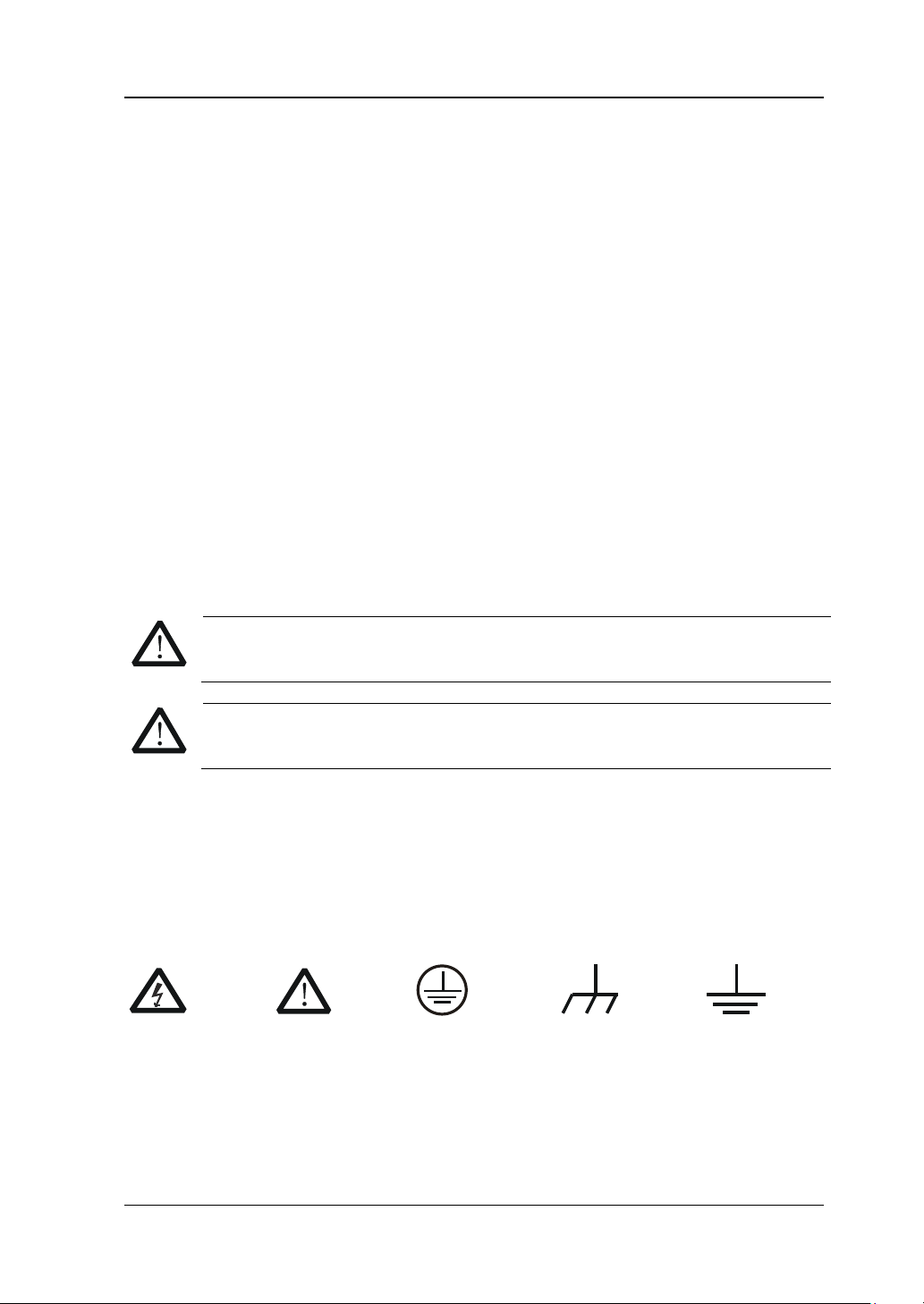
Symbols on the Product. These symbols may appear on the product:
Hazardous
Voltage
Safety
Warning
Protective
Earth
Terminal
Chassis
Ground
DG1000Z Quick Guide III
Test
Ground
RIGOL
CAUTION
WARNING
General Care and Cleaning
General Care:
Do not store or leave the instrument in where the instrument will be exposed to direct
sunlight for long periods of time.
Cleaning:
Clean the instrument regularly according to its operating conditions. T o clean the exterior
surface, perform the following steps:
1. Disconnect the instrument from all power sources.
2. Clean the loose dust on the outsi de of the ins trum ent wit h a li nt- free cloth (with a
mild detergent or water). When cleaning the LCD, take care to avoid scarifying it.
T o avoid damages to the instrument, do not expose them to liquids which have
causticity.
To avoid injury resulting from short circuit, make sure the instrument is
completely dry before reconnecting to a power source.
Environmental Considerations
The following symbol indicates that this product complies with the applicable European
Union requirements according to Dire c tives 2002/96/EC on waste electrical and
electronic equipment (WEEE) and batteries.
Product End-of-Life Handling
The equipment may contain substances that could b e harmful to the environment or
human health. In order to avoid release of such substances into the environment and
harm to human health, we encourage you to recycle this product in an appropriate
system that will ensure that most of the materials are reused or recycled appropriately.
Please contact your local authorities for disp osal or recycling information.
IV DG1000Z Quick Guide
RIGOL
Model
Channels
Max. Frequency
DG1032Z
2
30MHz
Document Overview
Format Conventions in this Manual
1. Button
The key at the front panel is denoted by the format of “Text Box + Button Name
(Bold)” in the manual, for example, Sine.
2. Menu:
The menu is denoted by the format of “Character Shading + Menu Word (B old)” in
the manual, for example, Freq.
3. Connector:
The connector at the front or rear panel is denoted by the format of “Square
Brackets + Connector Name (Bold) in the manual, for example, [Counter].
4. Operation Steps:
The next step of the operation is denoted by an arrow “” in the manual. For
example, Sine Freq denotes pressing Sine at the front panel and then pressing
Freq.
Content Conventions in this Manual
1. DG1000Z series function/arbitrary waveform generator includes DG1032Z and
DG1062Z. In this manual, DG1062Z is taken as an example to illustrate the ba sic
operations of the generator. For more details, please refer to DG1000Z Series
Function/Arbitrary Waveform Generator User’s Guide.
2. All models of DG1000Z series function/arbitrary waveform generator are equipped
Manuals of this Product
The manuals of this product mainly include the quick guide, user’s guide, programming
guide and data sheet. For the newest version of the desired manual, download it
from
DG1000Z Quick Guide V
DG1062Z 2 60MHz
with dual channels (CH1 and CH2). Unless otherwise specified, this manual takes
CH1 as an example to introduce the operation method which is also applied to CH2.
www.rigol.com.

RIGOL
Content
Guaranty and Declaration ................................................................................. I
Safety Requirement ........................................................................................ II
General Safety Summary ...................................................................................II
Safety Terms and Symbols ............................................................................... III
General Care and Cleaning ............................................................................... IV
Environmental Considerations ........................................................................... IV
Document Overview ........................................................................................ V
Quick Start ....................................................................................................... 1
General Inspection ............................................................................................ 1
To Adjust the Handle ......................................................................................... 2
Appearance and Dimensions .............................................................................. 3
Front Panel Overview ........................................................................................ 4
Rear Panel Overview ......................................................................................... 9
Power On and Inspection ................................................................................ 11
To Connect to Power ................................................................................ 11
Power-on Inspection ................................................................................ 11
To Set the System Language .................................................................... 11
User Interface ................................................................................................ 12
Dual Channels Parameters M ode ............................................................... 12
Dual Channels Graph Mode ...................................................................... 14
Single Channel Mode ................................................................................ 14
To Use the Built-in Help System ....................................................................... 15
Basic Operations ............................................................................................ 16
To Output Basi c Waveform .............................................................................. 16
To Output Arbitrary Waveform ......................................................................... 17
To Output Harmonics ...................................................................................... 19
To Output AM Modulated Waveform ................................................................. 21
To Output FSK Modulated Waveform ................................................................ 22
To Output Sweep Waveform ............................................................................ 23
To Output Burst Waveform .............................................................................. 24
Remote Control .............................................................................................. 26
Troubleshooting ............................................................................................. 28
VI DG1000Z Quick Guide

Quick Start
General Inspection
1. Inspect the shipping container for damage
Keep the damaged shipping container or cushioning material until the contents
of the shipment have been checked for completeness and the instrument has
passed both electrical and mechanical tests.
The consigner or carrier shall be liable for the damage to instrument resulting
from shipment. RIGOL would not be responsible for free mainten ance/rework
or replacement of the unit.
2. Inspect the instrument
In case of any damage, or defect, or failure, notify your RIGOL sales
representative.
3. Check the accessories
Please check the accessories according to the packing lists. If the accessories
are incomplete or damaged, please contact your RIGOL sales representative.
RIGOL
DG1000Z Quick Guide 1
RIGOL
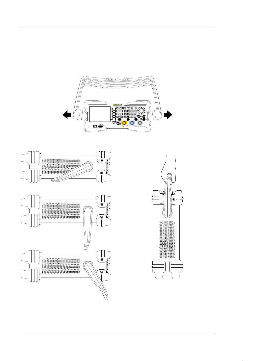
To Adjust the Ha ndle
To adjust the handle position of the instrument, please grip the handle by sides and
pull it outward. Then, rotate the handle to the desired position. The operating
method is shown below.
Adjusting the handle
Viewing Positions Carrying P osition
2 DG1000Z Quick Guide
RIGOL
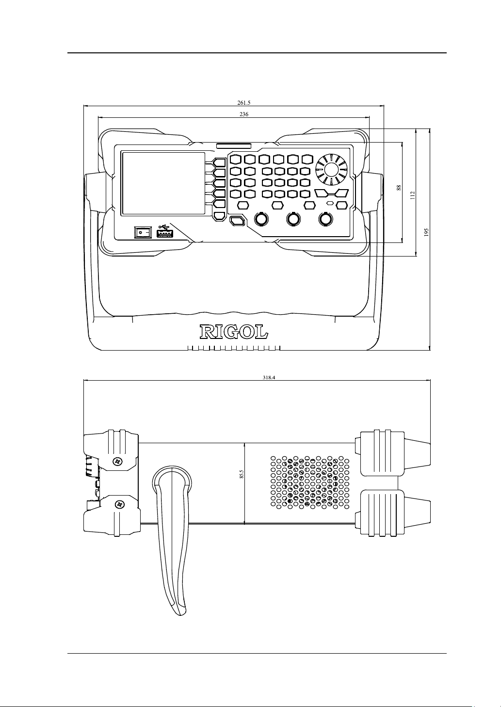
Appearance and Dimensions
Front View Unit: mm
Side View Unit: mm
DG1000Z Quick Guide 3
RIGOL
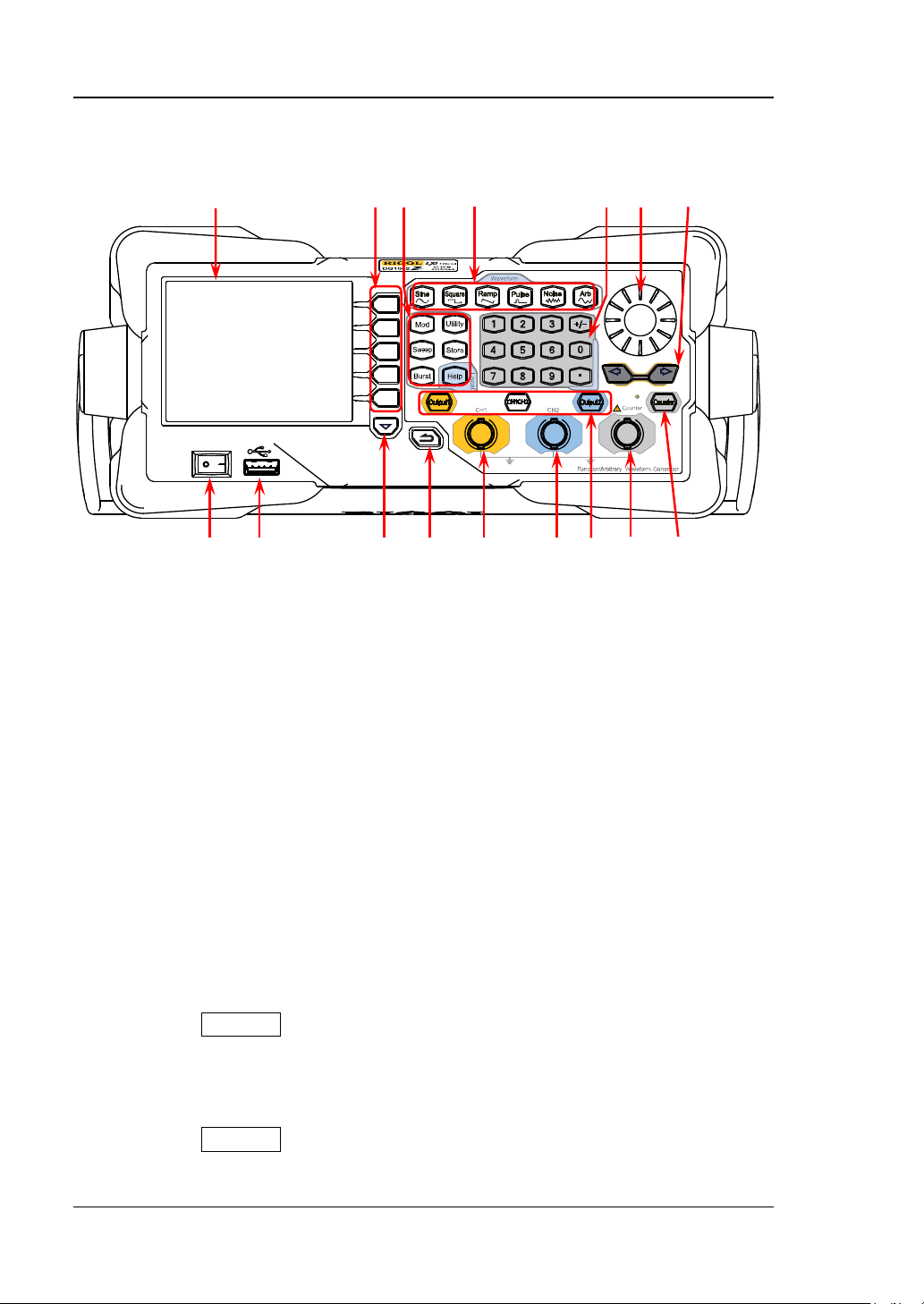
Front Panel Overview
16 15 14 13 12 11 10
1 2 3 4 5 6 7 8 9
Figure 1 Front Panel
1. Power Key
The power key is used to turn the generator on or off.
2. USB Host
The USB Host interface is used to be co nn ect ed a n US B st orag e dev i ce t o re ad
the saved waveform or state files or store the current instrument state and
edited waveform data into the USB storage device. In additional, the content
displayed in the sc reen is also can be saved as a picture file (*.Bmp) in the USB
storage device.
3. Page Down
This key is used to open the next page of the current menu.
4. Return to the Previous Menu
Quit the current menu and return to the previous menu.
5. CH1 Output Connector
BNC connector. The nominal output impedance is 50Ω.
When the Output1 is enabled (the backlight goes on), this connector outputs
the waveform based on the current settings of CH1.
6. CH2 Output Connector
BNC connector. The nominal output impedance is 50Ω.
When the Output2 is enabled (the backlight goes on), this connector outputs
the waveform based on the current settings of CH2.
4 DG1000Z Quick Guide

RIGOL
Press this key to open the output of CH1, the backlight goes
CAUTION
DC
7. Channel Control Area
Used to control the output of CH1.
—
on and the [CH1] connector outputs the waveform b ased on
the current settings of CH1.
— Press this key again to close the output of CH1 and the
backlight goes off.
Used to control the output of CH2.
— Press this key to open the output of CH2, the backlight goes
on and the [CH2] connector outputs t he wavef orm based on
the current settings of CH2.
— Press this key again to close the output of CH2 and the
backlight goes off.
Used to switch the current selected channel between CH1 and
CH2.
Overvoltage protection of CH1 and CH2 will take effect once any of the
following conditions is met. When overvoltage protection takes effect, a
message will be displayed and the output is disabled.
The input voltage is higher than ±11.5V±0.1V when the amplitude
of the generator is greater than 2Vpp or the DC offset is greater than
|2V
|.
DC
The input voltage is higher than ±3.5V±0.1V when the amplitude of
the generator is lower than or eq ual to 2Vpp or the DC offset i s
lower than or equal to |2V
8. Input Connector for the Signal Measured by Counter
BNC connector. The input impedance is 1MΩ. This connector is used to accept
the signal measured by the counter.
Note
To avoid d amage to the instrument, the input signal voltage cannot
exceed ±7Vac+dc.
9. Counter
Used to turn the counter on or off.
— Press this key to turn the counter on, the backlight goes on and the
indicator at the left of Counter blinks.
— Press this key again to turn the counter off and the backlight goes off.
|.
DG1000Z Quick Guide 5

RIGOL
Output Sine with frequency from 1μHz to 60MHz.
10. Direction Keys
— Used to move the cursor to select the digit to be edited when setting
parameter using knob.
— Used to delete the number at the left of the cursor when inputting
parameter using numeric keyboard.
— Used to unfold or fold the selected directory when storing or reading file.
— Used to move the cursor to select the desired character in filename input
area when editing filename.
11. Knob
— Used to increase (clockwise) or decrease (counterclockwise) the value
marked by the cursor when setting parameter using knob.
— Used to select the s torage location when storing a file or used to select the
file to be read when reading file.
— Used to select a character from the virtual ke yboard when editing filename.
— Used to select a desired built-in arbitrary waveform from Arb Select
Wform BuiltIn.
12. Numeric Keyboard
The numeric keyboard consists of number keys (0 t o 9), decimal point (.) and
sign key (+/-) and is used to set the parameters.
Note:
The si gn key is used to switch between uppercase and lowercase inputs.
Press the decimal point twice to save the content displayed in the user
interface in the USB storage device in *.Bmp format.
13. Waveform Keys
— The backlight goes on when this function is selected.
— You can set the parameters for sine waveform including
Freq/Period, Ampl/HiLevel, Offset/LoLevel and Start Phase.
Output Square with freque ncy from 1μHz to 25MHz and variable
duty cycle.
— The backlight goes on when this function is selected.
— You can set the parameters for square waveform including
Freq/Period, Ampl/HiLevel, Offset/LoLevel, Duty Cycle and
Start Phase.
Output Ramp with frequency from 1μHz to 1MHz and variable
symmetry.
— The backlight goes on when this function is selected.
— You can set the parameters for ramp waveform including
Freq/Period, Ampl/HiLevel, Offset/LoLevel, Symmetry and
Start Phase.
6 DG1000Z Quick Guide

RIGOL
Output Pulse with frequency from 1μHz to 25MHz and variable
You can set the parameters for pulse including Freq/Period,
Ampl/HiLevel, Offset/LoLev e l, Width/Duty, Leadin g , Trailing
Output Gaussian Noise with 60MHz bandwidth.
Output multiple types of modulated waveforms.
Output Sweep waveform for Sine, Square, Ramp and Arb
Used to set the auxiliary function parameters and system
pulse width and edge times.
— The backlight goes on when this function is selected.
—
and Start Phase.
— The backlight goes on when this function is selected.
— You can set the parameters for Noise including
Ampl/HiLevel and Offset/LoLevel.
Output Arbitrary wav efor m with fre quency from 1μHz to 10MHz.
— Support two output modes:
Sample Rate and Frequency.
— Up to 160 built-in waveforms.
— The backlight goes on when this function is selected.
— You can set the parameters for Arb waveform including
Freq/Period, Ampl/HiLevel, Offset/LoLevel and Start Phase.
14. Function Keys
— Support multiple modulation types: AM, FM, PM, ASK, FSK,
PSK and PWM.
— Support internal and external modulation sources.
— The backlight goes on when this function is selected.
(except DC).
— 3 Sweep types: Linear, Log and Step.
— 3 types of trigger sources: Internal, External and Manual.
— Provide frequency mark function used to control the status
of the sync s ignal.
— The backlight goes on when this function is selected.
Output Burst waveform for Sine, Square, Ramp, Pulse and Arb
(except DC).
— 3 Burst types: NCycle, Infinite and Gated.
— Noise can also be used to generate gated burst waveform.
— 3 types of trigger sources: Internal, External and Manual.
— The backlight goes on when this function is selected.
parameters. The backlight goes on when this function is
selected.
DG1000Z Quick Guide 7

RIGOL
Store or recall the instrument state or the user-defined arbitrary
the instrument is working in remote mode, press
waveform d a ta.
— A nonvolatile memory (C disk) is built in an d an USB stora ge
device (D disk) can be connected.
— The backlight goes on when this function is selected.
To get the help information of any front panel key or menu
so ftkey, press this key and then press the desired key.
Note: when
this key to retur n to l ocal mode.
15. Menu Softkeys
Correspond to the menus at the left and pressing the softkey will activate the
corresponding menu.
16. LCD
3.5 inches TFT (320×240) color LCD display. The current settings and state of
the instrument can be clearly displaye d. F or detailed information , refer to “User
Interface”.
8 DG1000Z Quick Guide

RIGOL
Rear Panel Overview
1 2 3 4 5 6
Figure 2 Rear Panel
1. [CH1/Sync/Ext Mod/Trig/FSK]
It is a BNC (female) connector which nominal imped ance is 50Ω. The function of
this connector is determined by the work mode of CH1.
— Sync: when the output of CH1 is enabled, this connector output the
corresponding sync signal.
— Ext Mod: when AM, FM, PM or PWM of CH1 is enabled and external
modulation source is selected, th is connec tor accepts an ex ternal
modulation signal.
— FSK: when ASK, FSK or PSK of CH1 is enabled and external modulation
source is selected, this connector accepts an external modulation signal
which polarity can be set by users.
— Trig In: when Sweep or Burst of CH1 is enabled and external trigger
source is selected, this connector accepts an external trigger signal which
polarity can be set by users.
— Trig Out: when Sweep or Burst of CH1 is enabled and internal or manual
trigger source is selected, this connector outputs the trigger signal with
specified edge type.
For more detailed information about the signals mentioned above, please refer
to the User’s Guide.
2. [CH2/Sync/Ext Mod/Trig/FSK]
It is a BNC (female) connector which nominal imped ance is 50Ω. The function of
this connector is determined by the work mode of CH2.
— Sync: when the output of CH2 is enabled, this connector output the
corresponding sync signal.
— Ext Mod: when AM, FM, PM or PWM of CH2 is enabled and external
DG1000Z Quick Guide 9

RIGOL
modulation source is selected, this connector accepts an ex ternal
modulation signal.
— FSK: when ASK, FSK or PSK of CH2 is enabled and external modulation
source is selected, this connector accepts an external modulation signal
which polarity can be set by users.
— Trig In: when Sweep or Burst of CH2 is enabled and external trigger
source is selected, this connector accepts an external trigger signal which
polarity can be set by users.
— Trig Out: when Sweep or Burst of CH2 is enabled and internal or manual
trigger source is selected, this connector outputs the trigger signal with
specified edge type.
For more detailed information about the signals mentioned above, please refer
to the User’s Guide.
3. [10MHz In/Out]
It is a BNC (female) conne ctor which nominal i mpedance is 50Ω. The function of
this connector is determined by the type of the clock source.
— When internal clock s ou rce is selecte d, this conne ct or (used as 10MH z Out )
outputs the 10MHz clock signal generated by the internal crystal oscillator
inside the generator.
— When external clock source is selected, this connector (used as 10MHz In)
accepts an external 10MHz clock signal.
This connector is typically used to synchronize multiple generators. For more
detailed information about the signals mentioned above , please refer to the
User’s Guide.
4. LAN Interface
Through this interfa ce, the gener ator can be conne cted to y our computer or the
network of y ou r c om pute r f or rem ote control . An integ rat ed testi ng syst em ma y
be built, as the generator conforms to the LXI-C class standar d o f LAN-based
instrument control.
5. USB Device Interface
This interface is used to connect a computer which can control the generator
remotely using PC software or by programming. It is also connected to a
PictBridge printer to print the content displayed in the screen.
6. AC Power Socket
The AC power supply specification of this signal generator is 100-240V,
45-440Hz. The maximum input power of the instrument cannot exceed 30W.
The specification of the fuse is 250V, T3.15A.
10 DG1000Z Quick Guide

RIGOL
CAUTION
Power On and Inspection
To Connect to Power
Please connect the generator to AC power supply using the power cord supplied in
the accessories as shown in the figure below. The AC power supply specification of
this generator is 100-240V, 45-440Hz. The maximum input power of the instrument
cannot exceed 30W. When the signal generator is connected to AC power supply via
this connector, the instrument select the correct voltage range aut omatically and
users do not need to select the voltage range manually.
Figure 3 Connect to Power
To avoid electric shock, make sure that the instrument is correctly
grounded.
Power-on Inspection
After the power sup ply is correctly connected, press the power key
panel to turn on the generator. During the start-up, the instrument performs
initialization and self-test. After that, the instrument enters the default interface. If
the instrument does not start normally, please refer to the “Troubleshooting”.
at the front
To Set the Syste m L anguage
DG1000Z series function/arbitrary generator supports Chinese and English system
languages. You can press Utility Language to switch the system language.
DG1000Z Quick Guide 11

RIGOL
7 8 9
10
Channel Output State:
Selected
Work Mode:
User Interface
The user interface of DG1000Z provides three types of display modes: Dual
Channels Parameters (default), Dual Channels Graph and Single Channel.
This manual mainly introduces the user interface taking the first display mode as an
example.
Dual Channels Parame ters Mode
6 5 4 3
Figure 4 User Interface (Dual Channels Parameters Mode)
1. Channel Output Configuration St atus Bar
Display the output configurations of the two channels.
AM/FM/PM/ASK/FSK/PSK/
Mod (Displayed when PWM
is enabled)/Sweep/ B u r s t
Waveform:
Sine
Squ
Ramp
Pulse
Noise
Arb
Harm
Type of Modulation
Source: Int/Ext
T ype of Sweep/Burst
Trig Source:
Int/Ext/Mu
1 2
Modulation Waveform of Analog Modulation:
Sine/Square/Tria/UpRamp/DnRamp/Noise/Arb
Polarity of Digital Modulation: Pos/Neg
Type of Sweep: LINE/LOG/SEG
Type of Burst: Ncycle/INF/Gate
Type of Output Impedance:
High Impedance: display HighZ
Load: display impedance value
(the default is 50Ω and the
range is 1Ω-10kΩ)
12 DG1000Z Quick Guide

RIGOL
2. Current Function
Display the function name selected currently. For example, “Sine” is displayed
when the sine is selected and “Edit” is display ed when the arbitrar y wave f orm
editing function is selected.
3. Menu
Display the operation menu of the function selected currently.
4. Status Bar
: Displayed when the instrument is connected to the LAN correctly.
: Displayed when the instrument is in remote mode.
: Displayed when an USB storage device is detected.
5. Waveform
Displayed the waveform currently selected by each channel.
6. Channel Status Bar
Used to indicating the selected status and on/off status of the channels. When
CH1 is selected, the border of the bar is displayed in yellow. When CH2 is
selected, the border of the bar is displayed in blue. When the output of CH1 is
enabled, the “CH1” in the bar is hi ghlighted in y ellow . When t he output of CH2 is
enabled, the “CH2” in the bar is highlighted in blue.
Note: you can e nable the outputs o f the tw o channe ls but y ou cannot sele ct th e
two channels at the same time.
7. Frequency
Display the wav eform frequency of the channel. Press Freq/Period to hi ghlight
“Freq” and use the numeric keyboard or knob to modify this parameter.
8. Amplitude
Display the waveform amplitude of the channel. Press Ampl/HiLevel to
highlight “Ampl” and use the numeric keyboard or kn ob to modify this
parameter.
9. Offset
Display the waveform DC offset of the channel. Press Offset/LoLevel to
highlight “Offset” and use the numeric keyboard or knob to modify this
parameter.
10. Phase
Display the waveform start phase of the channel. Press Start Phase and use
the numeric keyboard or knob to modify this parameter.
DG1000Z Quick Guide 13

RIGOL
Dual Channels Graph Mode
Press Utility System Display DispMode to select “Dual Graph”, as shown
in the figure below.
Figure 5 Use r Interface (Dual Channels Graph Mode)
Single Channel Mode
Press Utility System Display DispMode to select “Single View”, as shown
in the figure below.
Figure 6 Use r In t e rface (Single Channel Mode)
14 DG1000Z Quick Guide

RIGOL
To Use the Built-in Help System
The built-in help system of DG1000Z provides help information for each key and
menu softkey at the fr ont panel. Users can view the help of any key when operating
the instrument.
1. Acquire the built-in h elp
Press Help and the backlight goes on. Then press the desired key or menu
softkey and the corresponding help information is displayed.
2. Page up/down
When the help information is displa yed on multiple pages, use rs can a cquire the
help information on the previous or next page using
line)/
3. Turn off the current help information
When the help information is displayed in the interface, press ing any function
key (except Output1 and Output2) at the front panel will turn off the help
information currently display ed.
4. Main Help Top ic s
Press Help t wice to open the list of main help topics. Use
knob to select the desi red help topic an d press Select to view t he corres pondin g
help information.
(the next line)/ (page up)/ (page down) or the knob.
(the previous
/ / / or the
DG1000Z Quick Guide 15

RIGOL
Basic Operations
To Output Basic Waveform
DG1000Z can output basic waveforms (Sine, Square, Ramp, Pulse and Noise) from
one of the channels separately or from the two channels at the same tim e. This
section introduces how to output a sine waveform (Frequency: 20kHz, Amplitude:
2.5Vpp, DC O ffs et: 500mV
1. To select output channel
Press CH1|CH2 to select CH1. Now the boarder of the channel status bar is
displayed in yellow.
2. To select the Sine
Press Sine to select the sine waveform. The backlight goes on and the
corresponding menu is displayed in the right of the screen.
3. To set the frequency/period
Press Freq/Period to highlight “Freq”, and then use the numeric keyboard to
input 20. Then select kHz from the pop-up menu.
The frequency ranges from 1μHz to 60MHz.
The frequency units available are MHz, kHz, Hz, mHz and μHz.
Press this softkey again to switch to period setting.
The period units available are sec, msec, μsec and nsec.
4. To set the amplitude
Press Ampl/HiLevel to highlight “Ampl”, and use the numeric keyboard to
input 2.5. Then, select Vpp from the pop-up menu.
The amplitude range is limited by the impedance and frequency/period.
The amplitude units available are Vpp, mVpp, Vrms, mVrms and dBm (dBm
is only valid when the setting in Utility Channel Set Output Set
Imped is not HighZ).
Press this softkey again to switch to high level setting.
The high level units available are V and mV.
5. To set the offset
Press Offset/LoLevel to highlight “Offset”, and then use the nume ric key board
to input 500. Then, select mV
The range of the offset is limited by the impedance and frequency/period.
The DC offset voltage units available are V
Press this softkey again to switch to low level setting. The low lev el must be
lower than the high l evel a t least 1mV (when the output impedance is 50Ω).
The low level units available are V and mV.
DC, Start Ph ase: 90°) from the [CH1] connector.
DC from the pop-up menu.
and mVDC.
DC
16 DG1000Z Quick Guide

RIGOL
6. To set the start phase
Press Start Phase, and then use the numeric keyboard to input 90. Then,
select ° from the pop-up menu. The start phase r anges from 0° to 360°.
7. To enable the output
Press Output1 to turn CH1 output on. At this point, the backlight goes on and
the [CH1] connector outputs waveform with the specified parameters.
8. To observe the output waveform
Connect the [CH1] connector to the oscilloscope using BNC cable. The
waveform is as shown in the figure below.
Figure 7 Sine
To Output Arbitrary Waveform
DG1000Z can output the built-in or user-defined arbitra ry waveforms from a single
channel or from two channels at the same time. This section introduces how to
output an arbitrary waveform from the [CH1] connector (Edit Points, Sample editing
mode, Cycle Period: 1s, HiLevel: 4V, LoLevel: -2V, Points: 8, Volt age of Point#1 to
Point#4: 4V; Voltage of Point#5 to Point#8: -2V).
1. To select output channel
Press CH1|CH2 to select CH1. Now the boarder of the channel status bar is
displayed in yellow.
2. To enable arbitrary waveform
Press Arb to enter the arbitrary waveform setting interface. Please set the
frequency, amplitude, offset and start phase of the arbitrary waveform
according to “
To Output Basic Waveform”.
DG1000Z Quick Guide 17

RIGOL
3. To edit arbitrary waveform
Press Arb Edit Wform to open the arbitrary waveform editing menu.
1) Press Mode to select “Sample”.
2) Press Cycle Period, use the numer ic keyboard to in put 1 and selec t sec
from the po p -up menu.
3) Press HiLevel, use the numeric keyboard to input 4 and selec t V fro m th e
pop-up menu.
4) Press LoLevel, use the numeric ke yboa rd to in put -2 and select V from the
pop-up menu.
5) Press Points, use the numeric keyboard to input 8 and press Sure. At this
point, a -2V level line appears.
6) Press Edit Points to enter the points editing interface.
Press Sample to define the first point. Press Voltage, use the
numeric keyboard to input 4 and select V from the pop-up menu.
Press Sample again, use the numeric keyboard or knob to s elect point
2; then press Voltage to input 4V.
Define the voltage of point 3 to point 8 according to the method
mentioned above.
4. To select waveform
Press Arb Select Wform Vola tile Wfo rm to select the waveform edited.
5. To enable the output
Press Output1 to turn CH1 output on. At this point, the backlight goes on and
the [CH1] connector outputs arbitrary w avef orm with the spe cified parameters.
6. To observe the output waveform
Connect the [CH1] connector to the oscillosco pe using BNC cable. Now , you can
observe the waveform via the oscilloscope.
18 DG1000Z Quick Guide

RIGOL
To Output Harmonics
DG1000Z can be used as a harmonic generator to output harmonic with specified
order, amplitude and phase. This section introduces how to output the 2
harmonics from the [CH1] connector (Amplitude: 2Vpp and 1Vpp, Pha se : 30 ° and
50°, Order: 5).
1. To select output channel
Press CH1|CH2 to select CH1. Now the boarder of the channel status bar is
displayed in yellow.
2. To set the parameters of the fundamental waveform
Set the frequency/period, amplitude/high level, offset/low level and start phase
of the fundamental waveform according to “To Output Ba sic Waveform”.
3. To enable the harmonic function
Press Sine Harm to select “On”. Press Harmonic Para to enter the
harmonic setting menu.
4. To set harmonic order
Press Order in the harmo nic set ting menu, use the numeric k eyboar d to in put 5
and press Sure.
The range is li mited by the maximum output frequency of the instrument as
well as the fundamental waveform frequency.
Range: integers within 2 to maximum output frequency of the
instrument ÷ fundamental waveform frequency. The maximum is 8.
5. To select harmonic type
Press Type in the harmonic setting menu to select Even or User.
Method 1: Even
Press this key and the instrument would output fundamental waveform and
even harmonics (the 2
nd
and 4th harmonics).
Method 2: User
Press this key and the instrument would output the user-defined orders of
harmonics. The highest order is 8.
8 bits binary data is used to represent the output status of the 8 orders of
harmonics respectively, wherein , 1 represents enabling the output of the
corresponding harmonic and 0 represents disabling t he output of the
corresponding harmonic. Users only need to use the numeric keyboard to
modify the value of each data bit (note: the leftmost bit representing
fundamental waveform is always X and cannot be modified). For example, set
the 8 bits data to X101 0000, thus 2
nd
and 4th orders of harmonics are output.
Note: the actual harmonics output is determined by the “Order” and “Type”
currently specified.
nd
and 4th
DG1000Z Quick Guide 19

RIGOL
6. To set harmonic amplitude
Press Harmonic Ampl in the harmonic setting menu to set the amplitude of the
nd
and 4th harmonics.
2
1) Press SN, use the numeric keyboard to input 2 and press Sure.
2) Press Harmonic Ampl, use the numeric keyboard to input 2 and select
Vpp from the pop-up menu.
3) Set the amplitude of the 4th harmonic to 1Vpp according to 1) and 2).
7. To set harmonic phase
Press Ha rmonic Phase in the harmonic setting menu to set th e phas e of the
nd
and 4th harmonics.
2
1) Press SN, use the numeric keyboard to input 2 and press Sure.
2) Press Harmonic Phase, use the nu meric keyboar d to input 30 and se lect °
from the pop-up menu.
3) Set the phase of the 4th harmonic to 50° according to 1) and 2).
9. To enable the output
Press Output1 to turn CH1 output on. At this point, the backlight goes on and
the [CH1] connector outputs the fundamental waveform as well as the 2nd and
th
harmonics.
4
10. To observe the output waveform
Connect the [CH1] connector to the oscilloscope using BNC cable. The
waveform is as shown in Figure 9.
Figure 8 Harmonics
20 DG1000Z Quick Guide

RIGOL
To Output AM Modulated Waveform
For amplitude modulation (AM), the amplitude of the carrier waveform varies with
the instantaneous voltage of the mo dulati ng waveform. This section introduces how
to output AM modulated waveform from the [CH1] connector (the carrier is si ne
with 5kH z frequency and 5Vp p amplitude, the modulating waveform is sine with
200Hz frequency and the modulation depth is 80%).
1. To select output channel
Press CH1|CH2 to select CH1. Now the boarder of the channel status bar is
displayed in yellow.
2. To set the carrier waveform shape, frequency and amplitude
1) Carrier Wa veform Shape: press Sine to select sine as t he carrier wa veform.
2) Carrier Frequency: press Freq/Period to highlight “Freq”. At this point, use
the numeric keyboard to input 5. Then, select kHz from the pop-up menu.
3) Carrier Amplitude: press Ampl/HiLevel to highlight “Ampl”, and then use
the numeric keyboard to input 5. Then, select Vpp from the pop-up menu.
3. To select AM modulation
Press Mod Type AM to enable AM function.
When Mod is enabled, Sweep or Burst will be disabled automatically (if
enabled currently).
Int and AM will be displayed in the bottom of the screen.
4. To set Modulating waveform frequency
Press AM F req, and then us e the numeric keyboard to input 200. Then, select
Hz from the pop-up menu.
5. To select modulating waveform
Press Shape to select Sine from the pop-up menu.
6. To set modulation depth
Press AM Depth, and then use the numeric keyboard to input 80. Then,
select % from the pop-up menu.
7. To enable the output
Press Output1 to turn CH1 output on. At this point, the backlight goes on and
the [CH1] conne ctor outputs t he AM modulated wa vef orm based o n the cur rent
settings.
8. To observe the output waveform
Connect the [CH1] connector to the oscilloscope using BNC cable. The
waveform is as shown in the figure below.
DG1000Z Quick Guide 21

RIGOL
Figure 9 AM Modulated Waveform
To Output FSK Modulated Waveform
For FSK (Frequency Shift Keying) modulation, the generat o r “shifts” its output
frequency between two preset frequencies (carrier frequency and hop frequency).
This section introduces how to output FSK modulated waveform from the [CH1]
connector (the carrier is sine with 3kHz frequency and 5Vpp amplitude, the hop
frequency is 500Hz, the FSK rate is 100Hz and the modulating polarity is Pos).
1. To select output channel
Press CH1|CH2 to select CH1. Now the boarder of the channel status bar is
displayed in yellow.
2. To set the carrier waveform shape, frequency and amplitude
1) Carrier Wa veform Shape: press Sine to select sine as t he carrier wa veform.
2) Carrier Frequency: press Freq/Period to highlight “Freq”. At this point, use
the numeric keyboard to input 3. Then, select kHz from the pop-up menu.
3) Carrier Amplitude: press Ampl/HiLevel to highlight “Ampl”, and then use
the numeric keyboard to input 5. Then, select Vpp from the pop-up menu.
3. To select FSK modulation
Press Mod Type FSK to enable FSK function.
When Mod is enabled, Sweep or Burst will be automatically disabled (if
enabled currently).
Int and FSK will be displayed in the bottom of the screen.
4. To set hop frequency
Press Hop Freq, use the numeric key board to in put 500 an d select H z f rom th e
pop-up menu.
22 DG1000Z Quick Guide

RIGOL
5. To set FSK rate
Press FSK Rate, use the numeric k eyboa rd to input 100 and sele ct Hz from th e
pop-up menu.
6. To set modulating polarity
Press Polarity to select the Pos polarity of the modulating wave f or m to cont r ol
the output frequency. At this point, the generator would output the carrier
frequency when the modulating waveform is logic low and output the hop
frequency when the modulating waveform is logic high.
7. To enable the output
Press Output1 to turn CH1 output on. At this point, the backlight goes on and
the [CH1] connector outputs the FSK modulated waveform based on the
current settings.
8. To observe the output waveform
Connect the [CH1] connector t o the os cilloscope using BNC cable. N ow, you ca n
observe the waveform via the oscilloscope.
To Output Sweep Waveform
DG1000Z can output sweep waveform from a single channel or from dual channels at
the same time. This section introduces how to output sweep waveform from the
[CH1] connector (Linear sweep type, the carrier is sine with 5Vpp amplitude, the
frequency range is 50Hz~1kHz, Sweep Time: 1s, Internal trigger source).
1. To select output channel
Press CH1|CH2 to select CH1. Now the boarder of the channel status bar is
displayed in yellow.
2. To set the carrier waveform shape and amplitude for sweep
1) Waveform: Press Sine to select sine as the carrier waveform.
2) Amplitude: Press Ampl/HiLevel to highlight “Ampl”, and then use the
numer ic keyboard to input 5. Then, select Vpp from the pop-up menu.
3. To enable sweep function
Press Sweep to enable the sweep function (the backlight of the key goes on).
When Sweep is enabled, Mod or Burst function will be automatically
disabled (if currently enabled).
Int and Sweep will be displayed in the bottom of the screen.
4. To select sweep type
Press Type to select Linea r. At this point, a w hite line appea rs
on the waveform in the screen as shown in the right figure.
DG1000Z Quick Guide 23

RIGOL
5. To set the start frequency and stop frequency
1) Start Frequency
Press Start/Center to highlight “Start”, and then use the numeric
keyboard to inpu t “50”. Then, select Hz from the pop-up menu.
2) Stop Frequency
Press Stop/Span to highlight “Stop”, and then use the numeric keyboard
to input 1. Then, select Hz from the pop-up menu.
6. To set the sweep time
Press Sweep Time to input 1 using the numeric keyboard and select sec from
the pop-up menu.
7. To select the trigger source
Press Trigger Source to select Int trigger source.
9. To enable the output
Press Output1 to turn CH1 output on. At this point, the backlight goes on and
the [CH1] connector outputs the sweep waveform based on the current
settings.
10. To observe the output waveform
Connect the [CH1] connector t o the os cilloscope using BNC cable. Now , y ou can
observe the waveform via the oscilloscope.
To Output Burst Waveform
DG1000Z can output wa vef orm with specified number of cycles (called burst) from a
single channel or from dual channels at the same time. This section introduces how
to output burst from the [CH1] connector (3 cycles, the carrier is sine with 5Vpp
amplitude and 1ms period , Burst P eriod: 10 ms, Inte rnal trig ger sou rce, Delay: 1ms).
1. To select output channel
Press CH1|CH2 to select CH1. Now the boarder of the channel status bar is
displayed in yellow.
2. To set the carrier waveform shape and amplitude for burst
1) Waveform: Press Sine to select sine as the carrier waveform.
2) Amplitude: Press Ampl/HiLevel to highlight “Ampl”, and then use the
numeric keyboard to input 5. Then, select Vpp from the pop-up menu.
3) Period: Press Freq/Period to highlight “Period”, and then use the numeric
keyboard to inpu t 1. Then, select msec from the pop-up menu.
3. To enable burst function
Press Burst to enable the burst function (the backlight of the key goes on).
When Burst is enabled, Mod or Sweep function will be automatically
24 DG1000Z Quick Guide

RIGOL
disabled (if currently enabled).
Int and Burst will be disp layed in the bottom of the screen.
4. To set the burst type and Cycles
Press Type to select NCycle . At this point, the Cycles in the screen is highlighted
and can be edited. Use the numeric keyboard to input 3 and press Sure.
5. To set burst period
Burst period is only available for N cycle burst in internal trigger and is defined
as the time from the start of a burst to the start of the next burst.
Press Burst Period to input 10 using the numeric keyboard and select msec
from the pop-up menu.
6. To select burst trigger source
Press Trigger Source to select Int trigg e r s ource.
7. To set the delay
Burst delay is only available for N cycle and infinite burst type. It is defined as
the time from when the generator receives the trigger signal to starts to output
the N Cycle (or Infinite) burst. Press Delay, and then use the numeric ke yboar d
to input 1. Then select msec from the pop-up menu.
8. To enable the output
Press Output1 to turn CH1 output on. At this point, the backlight goes on and
the [CH1] connector outputs the burst wa veform based on the current settings.
9. To observe the output waveform
Connect the [CH1] connector to the oscilloscope using BNC cable. The
waveform is as shown in the figure below.
Figure 10 Burst
DG1000Z Quick Guide 25

RIGOL
Remote Control
DG1000Z can communicate with PC through t he USB, LAN or GPIB (option) inte rface
to realize remote control on the basis of the SCPI commands (Standard Commands
for Programmable Instruments). This section introduces how to control the
generator remotely by sending the SCPI commands us ing U l tra Sigma provi d ed by
RIGOL via the USB interface. For detailed information a b out the commands, please
refer to the Programming Guide .
When the instrument is working in remote mode, the
the screen and the keys (exc ept Help ) at the front panel are locked. Now you can
return the instrument to local mode by pressing Help.
1. To install Ultra Sigma
Acquire the Ultra Sigma software and install it as well as its components
according to the instructions. This software is contained in the resource CD in
the standard accessories. You can also download the latest version of the
software from
2. To control the genera tor via USB
1) Connect the device
Connect the generator (USB Device) and PC (USB Host) using USB cable.
2) Install USB drive
This generator is USB-TMC device and the New Hardware Wizard will be
displayed after the generator is correctly connected to the PC (the
generator will be automatically configured to USB interface) and both of
them are started. Please install the “USB Test and Measurement Device”
drive program according to the instructions.
3) Search for device resource
Start Ultra Sigma and the software will search for the generator resource
currently connected to the PC automatically. You can also click
4) View device resource
The resource found together with the instrument model and USB interface
information will be displayed under the “RIGOL Online Resource” directory,
as shown in Figure 12.
www.rigol.com.
to search for the resource manually.
indicator is displayed in
26 DG1000Z Quick Guide

RIGOL
Figure 11 To View USB Instrument Resource
5) Communication test
Right-click the resource name DG1062Z
(USB0::0x1AB1::0x0642::DG1A000001::INSTR) and select SCPI Panel
Control to o pen the remote command control panel through which you can
send commands and read data.
Figure 12 Send and Read Commands via USB
DG1000Z Quick Guide 27

RIGOL
Troubleshooting
The commonly encountered failures and their solutions are listed below. When you
encounter those problems, please solve them following the corresponding steps. If
the problem remains still, please contact RIGOL and provide your devi ce
information (Utility System Info).
1. The screen of the generator is still dark (no display) after pressing the
power key:
1) Check whether the power is correctly connected.
2) Check whether the power key is really pressed.
3) Restart the instrument after finishing the above inspections.
4) If it still does not work correctly, please contact RIGOL.
2. The screen is too dark and cannot be seen clearly:
1) Check whether the brightness setting of the LCD screen is too low.
2) Press Utility System Display to enter the display setting menu.
Press Bright and Contrast and use the numeric keyboard or the knob to
adjust the brightness and contrast of the LCD screen to a proper value
respectively.
3. The generator is locked:
1) Check whether the generator is in remote control mode (in remote control,
is displayed in the status bar of the user interface ). Pressing Help can
exit the remote control mode and unlock the front panel.
2) Restarting the generator can also unlock the instrument.
4. The settings are correct but no waveform is generated:
1) Check if the BNC cable is t ightly conne cted to the correspondin g [Output1]
or [Output2] connector.
2) Check whether the connecting wire has internal damage.
3) Check whether the BNC cable is tightly connected to the test instrument.
4) Check whether the backlight of Output1 or Output2 goes on. If not,
press corresponding key to illuminate the backlight.
5) Press Utility System Power On to sel ect Last and then restart the
instrument after finishing the above inspections.
6) If it does not work correctly, please contact RIGOL.
5. The USB storage device cannot be recognized:
1) Check whether the USB storage device can work normally when connected
to other instrument or PC.
2) Make sure that the USB storage device used is Flash type. This instrument
does not support hardware USB storage device.
3) Restart the instrument and i nsert the US B storage again to c heck whether it
can work norm a l l y.
28 DG1000Z Quick Guide

RIGOL
4) If the USB storage device still cannot be used normally, please contact
RIGOL.
6. How to set the amplitude of the waveform in dBm?
1) Press CH1|CH2 to select desired channel.
2) Check whether the setting in Utility Channel Set Output Set
Imped is HighZ. If y e s, you cannot set the amplitude in dBm. Please press
Imped to select Load a nd u s e t h e num e ric keyboard or knob to set the
impedance to a proper value.
3) Select desired waveform, press Ampl/HiLevel to highlight “Ampl”, and
then use the numeric keyboard to input desired value. Then select dBm
from the pop-up menu.
7. Performance verification test is not passed:
(1) Check whether the generator is within calibration period (1 year).
(2) Make sure that the generator is warmed up for at least 30 minutes before
test.
(3) Check whether the generator is under the specified temperature.
(4) Check whether the test is under the magnetic environment.
(5) Check whether the power supplies of generator and test system have
strong interference.
(6) Check whether the performance of the test device meets the requirement.
(7) Make sure that the test device is within calibration period.
(8) Check whether the test device meets the required conditions of the manual.
(9) Check whether all connections are tight.
(10) Check whether all cables have internal damage.
(11) Make sure that the operati ons c onform t o sett ings a nd pro cesses which are
required by the performance verification manual.
(12) Check whether the error calculation is a mistake.
(13) The definitions of “Typical Value” for this product should be correctly
understood: the performance specification of this product unde r spe cified
conditions.
DG1000Z Quick Guide 29
 Loading...