

Page 1

RIGOL
快速指南
DG1000Z 系列
函数/任意波形发生器
2014 年 1 月
RIGOL Technologies, Inc.
Page 2

Page 3

RIGOL
保证和声明
版权
© 2013 北京普源精电科技有限公司版权所有。
商标信息
RIGOL 是北京普源精电科技有限公司的注册商标。
文档编号
QGB09002-1110
声明
本公司产品受已获准及尚在审批的中华人民共和国专利的保护。
本公司保留改变规格及价格的权利。
本手册提供的信息取代以往出版的所有资料。
对于本手册可能包含的错误,或因手册所提供的信息及演绎的功能,以及因使用本手
册而导致的任何偶然或继发的损失,RIGOL 概不负责。
未经 RIGOL 事先书面许可不得影印复制或改编本手册的任何部分。
产品认证
RIGOL 认证本产品符合中国国家产品标准和行业产品标准及 ISO9001:2008 标准和
ISO14001:2004 标准,并进一步认证本产品符合其它国际标准组织成员的相关标准。
联系我们
如您在使用此产品或本手册的过程中有任何问题或需求,可与 RIGOL 联系:
电子邮箱:service@rigol.com
网址:www.rigol.com
DG1000Z 快速指南 I
Page 4

RIGOL
安全要求
一般安全概要
了解下列安全性预防措施,以避免受伤,并防止损坏本产品或与本产品连接的任何产品。
为避免可能的危险,请务必按照规定使用本产品。
使用正确的电源线。
只允许使用所在国家认可的本产品专用电源线。
将产品接地。
本产品通过电源电缆的保护接地线接地。为避免电击,在连接本产品的任何输入或输出端
子之前,请确保本产品电源电缆的接地端子与保护接地端可靠连接。
查看所有终端额定值。
为避免起火和过大电流的冲击,请查看产品上所有的额定值和标记说明,请在连接产品前
查阅产品手册以了解额定值的详细信息。
使用合适的过压保护。
确保没有过电压(如由雷电造成的电压)到达该产品。否则操作人员可能有遭受电击的危
险。
请勿开盖操作。
请勿在仪器机箱打开时运行本产品。
避免电路外露。
电源接通后,请勿接触外露的接头和元件。
怀疑产品出故障时,请勿进行操作。
如果您怀疑本产品出现故障,请联络RIGOL授权的维修人员进行检测。任何维护、调整
或零件更换必须由RIGOL授权的维修人员执行。
保持适当的通风。
通风不良会引起仪器温度升高,进而引起仪器损坏。使用时应保持良好的通风,定期检查
通风口和风扇。
请勿在潮湿环境下操作。
为避免仪器内部电路短路或发生电击的危险,请勿在潮湿环境下操作仪器。
请勿在易燃易爆的环境下操作。
为避免仪器损坏或人身伤害,请勿在易燃易爆的环境下操作仪器。
II DG1000Z 快速指南
Page 5
RIGOL
警告
注意
危险
警告
注意
请保持产品表面的清洁和干燥。
为避免灰尘或空气中的水分影响仪器性能,请保持产品表面的清洁和干燥。
防静电保护。
静电会造成仪器损坏,应尽可能在防静电区进行测试。在连接电缆到仪器前,应将其内外
导体短暂接地以释放静电。
注意搬运安全。
为避免仪器在搬运过程中滑落,造成仪器面板上的按键、旋钮或接口等部件损坏,请注意
搬运安全。
安全术语和符号
本手册中的术语。以下术语可能出现在本手册中:
警告性声明指出可能会危害操作人员生命安全的条件和行为。
注意性声明指出可能导致本产品损坏或数据丢失的条件和行为。
产品上的术语。以下术语可能出现在产品上:
表示您如果进行此操作可能会立即对您造成危害。
表示您如果进行此操作可能会对您造成潜在的危害。
表示您如果进行此操作可能会对本产品或连接到本产品的其他设备造成损坏。
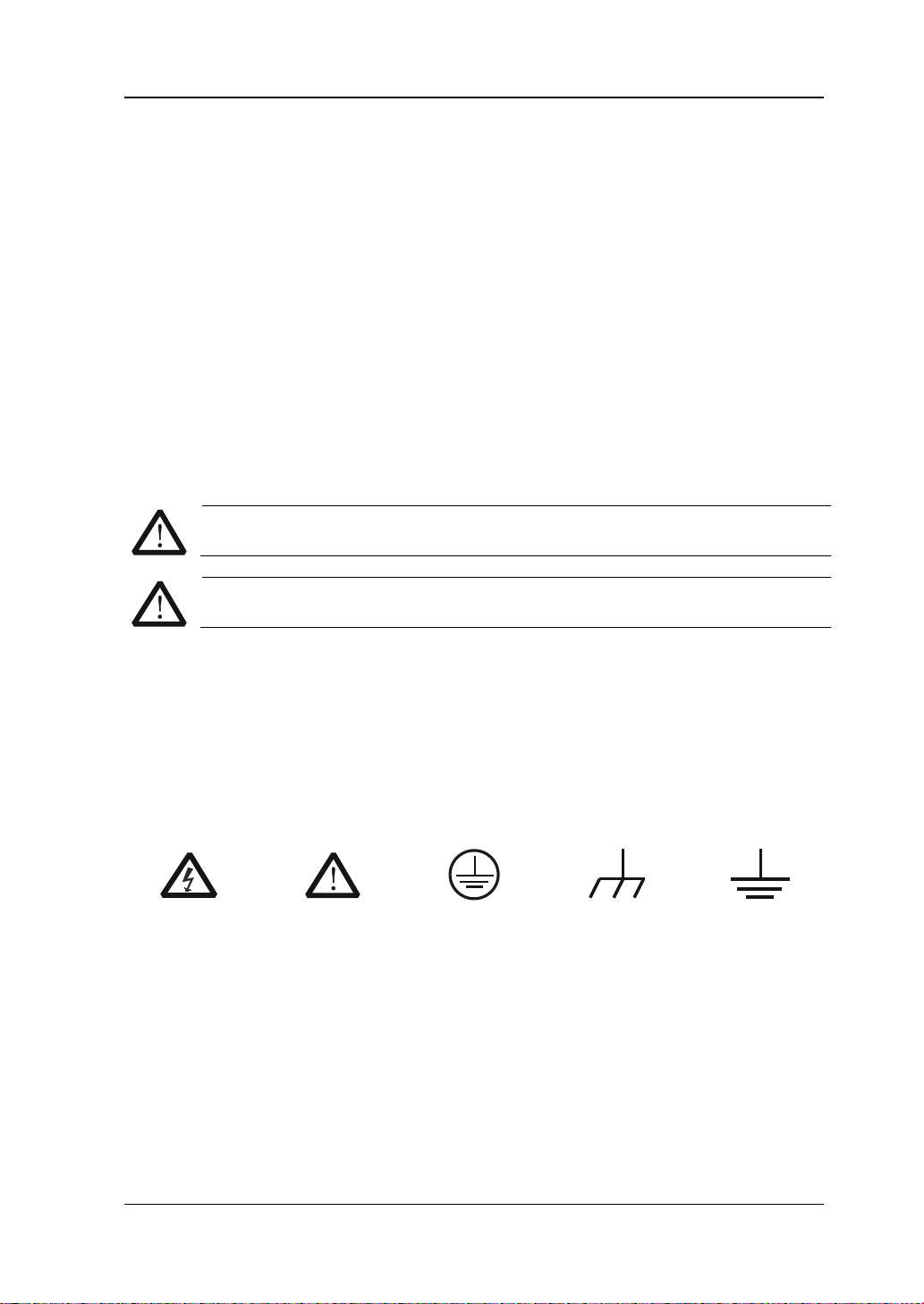
产品上的符号。以下符号可能出现在产品上:
高电压
安全警告
保护性接地端
壳体接地端
测量接地端
DG1000Z 快速指南 III
Page 6
RIGOL
注意
警告
保养与清洁
保养
请勿将仪器放置在长时间受到日照的地方。
清洁
请根据使用情况经常对仪器进行清洁。方法如下:
1. 断开电源。
2. 用潮湿但不滴水的软布(可使用柔和的清洁剂或清水)擦试仪器外部的浮尘。清洁带
有液晶显示屏的仪器时,请注意不要划伤 LCD 显示屏。
请勿使任何腐蚀性的液体沾到仪器上,以免损坏仪器。
重新通电之前,请确认仪器已经干透,避免因水分造成电气短路甚至人身伤害。
环境注意事项
以下符号表明本产品符合欧盟根据关于废弃电气、电子设备(WEEE)的Directive
2002/96/EC 所制定的要求。
设备回收
本产品中包含的某些物质可能会对环境或人体健康有害,为避免将有害物质释放到环境中
或危害人体健康,建议采用适当的方法回收本产品,以确保大部分材料可正确地重复使用
或回收。有关处理或回收的信息,请与当地权威机构联系。
IV DG1000Z 快速指南
Page 7
RIGOL
型号
通道数
最大输出频率
DG1032Z
2
30MHz
文档概述
文档中的格式约定
1. 按键:
本手册中通常用“文本框+文字(加粗)”表示前面板上的一个按键,如 Sine。
2. 菜单:
本手册通常用“字符底纹+文字(加粗)”表示一个菜单,如 频率。
3. 连接器:
本手册中通常用“方括号+文字(加粗)”表示前面板或后面板上的一个连接器。例如:
[Counter]。
4. 操作步骤:
本手册中通常用一个箭头“”表示下一步操作。例如:Sine 频率 表示按下前面
板上的 Sine 功能键后再按 频率 菜单软键。
文档中的内容约定
1. DG1000Z 系列函数/任意波形发生器包含 DG1032Z 和 DG1062Z 两个型号。本手册以
DG1062Z 为例,介绍其基本操作。有关更多详细信息,请参考《DG1000Z 系列函数/
任意波形发生器用户手册》。
DG1062Z 2 60MHz
2. DG1000Z 系列函数/任意波形发生器均具有 CH1 和 CH2 两个通道。本文如无特殊说
明,均以 CH1 为例介绍信号发生器的操作方法。CH2 的操作方法与 CH1 相同。
本产品用户文档
本产品的主要用户文档包括快速指南、用户手册、编程手册、数据手册等。用户可以登
录
www.rigol.com下载所需文档的最新版本。
DG1000Z 快速指南 V
Page 8

RIGOL
目录
保证和声明 .......................................................................................................... I
安全要求 ........................................................................................................... II
一般安全概要 ...................................................................................................II
安全术语和符号 .............................................................................................. III
保养与清洁 ...................................................................................................... IV
环境注意事项 .................................................................................................. IV
文档概述 ............................................................................................................ V
快速入门 ............................................................................................................ 1
一般性检查 ....................................................................................................... 1
调整手柄 .......................................................................................................... 2
外观尺寸 .......................................................................................................... 3
前面板概述 ....................................................................................................... 4
后面板概述 ....................................................................................................... 8
开机检查 ........................................................................................................ 10
连接电源 ................................................................................................. 10
开机 ........................................................................................................ 10
设置系统语言 .......................................................................................... 10
用户界面 ........................................................................................................ 11
双通道参数模式 ....................................................................................... 11
双通道图形模式 ....................................................................................... 13
单通道显示模式 ....................................................................................... 13
使用内置帮助系统 ........................................................................................... 14
基本操作 .......................................................................................................... 15
输出基本波形 ................................................................................................. 15
输出任意波 ..................................................................................................... 17
输出谐波 ........................................................................................................ 18
输出AM已调波形 ............................................................................................. 19
输出FSK已调波形 ............................................................................................ 21
输出Sweep波形 .............................................................................................. 22
输出Burst波形 ................................................................................................ 23
远程控制 ........................................................................................................ 24
故障处理 .......................................................................................................... 26
VI DG1000Z 快速指南
Page 9

快速入门
一般性检查
1. 检查运输包装
如运输包装已损坏,请保留被损坏的包装或防震材料,直到货物经过完全检查且
仪器通过电性和机械测试。
因运输造成仪器损坏,由发货方和承运方联系赔偿事宜。RIGOL 公司恕不进行
免费维修或更换。
2. 检查整机
若存在机械损坏或缺失,或者仪器未通过电性和机械测试,请联系您的 RIGOL
经销商。
3. 检查随机附件
请根据装箱单检查随机附件,如有损坏或缺失,请联系您的 RIGOL 经销商。
RIGOL
DG1000Z 快速指南 1
Page 10
RIGOL
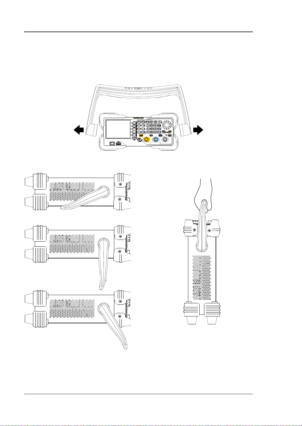
调整手柄
要调整仪器的手柄,请握住仪器两侧的手柄并向外拉。然后将手柄旋转到所需位置。
操作方法如下图所示。
调整手柄
平放位置 移动位置
2 DG1000Z 快速指南
Page 11
RIGOL
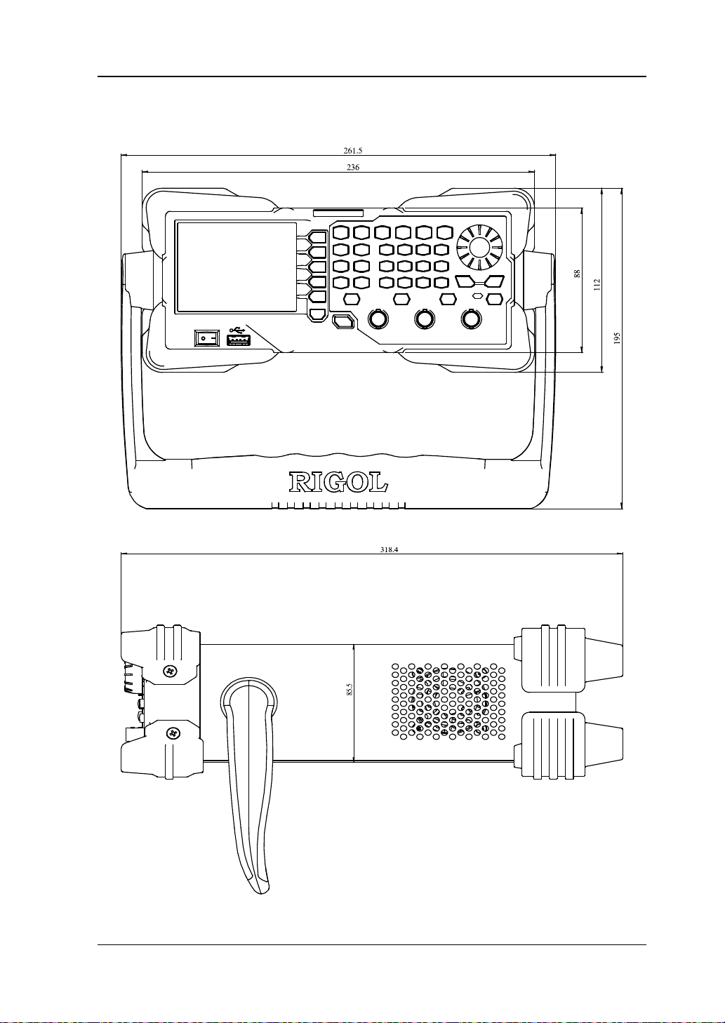
外观尺寸
正视图 单位:mm
侧视图 单位:mm
DG1000Z 快速指南 3
Page 12
RIGOL
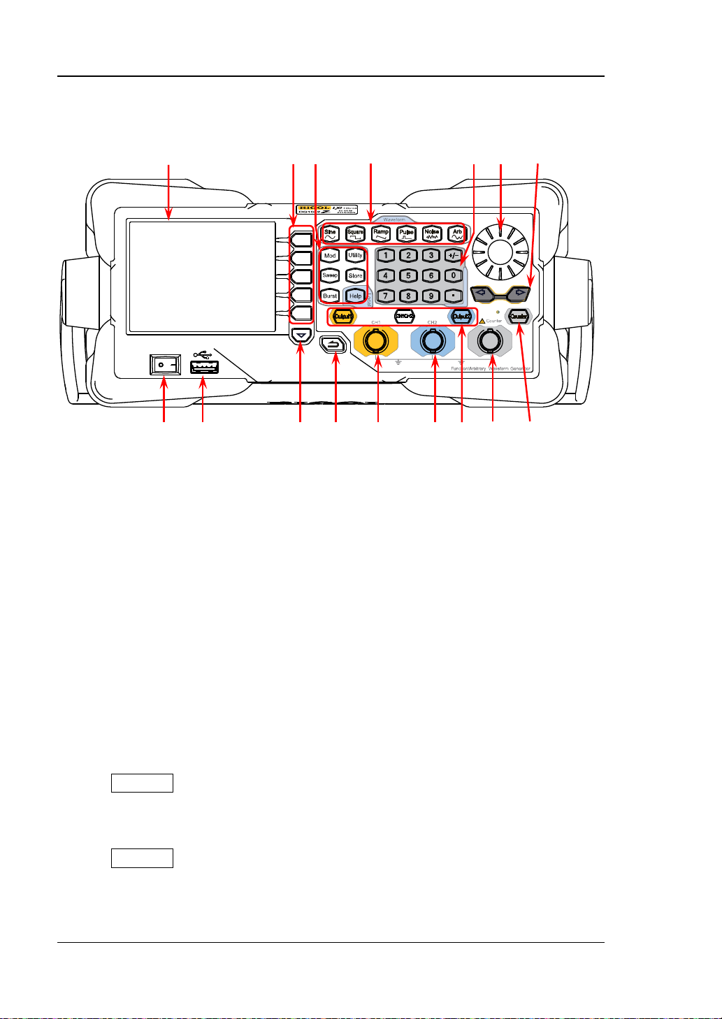
前面板概述
16 15 14 13 12 11 10
1 2 3 4 5 6 7 8 9
图 1 前面板
1. 电源键
用于开启或关闭信号发生器。
2. USB Host
可插入 U 盘,读取 U 盘中的波形文件或状态文件,或将当前的仪器状态或编辑的
波形数据存储到 U 盘中,也可以将当前屏幕显示的内容以图片格式(*.Bmp)保
存到 U 盘。
3. 菜单翻页键
打开当前菜单的下一页。
4. 返回上一级菜单
退出当前菜单,并返回上一级菜单。
5. CH1 输出连接器
BNC 连接器,标称输出阻抗为 50Ω。
当 Output1 打开时(背灯变亮),该连接器以 CH1 当前配置输出波形。
6. CH2 输出连接器
BNC 连接器,标称输出阻抗为 50Ω。
当 Output2 打开时(背灯变亮),该连接器以 CH2 当前配置输出波形。
4 DG1000Z 快速指南
Page 13
RIGOL
CH2
CH1或CH2
注意
注意
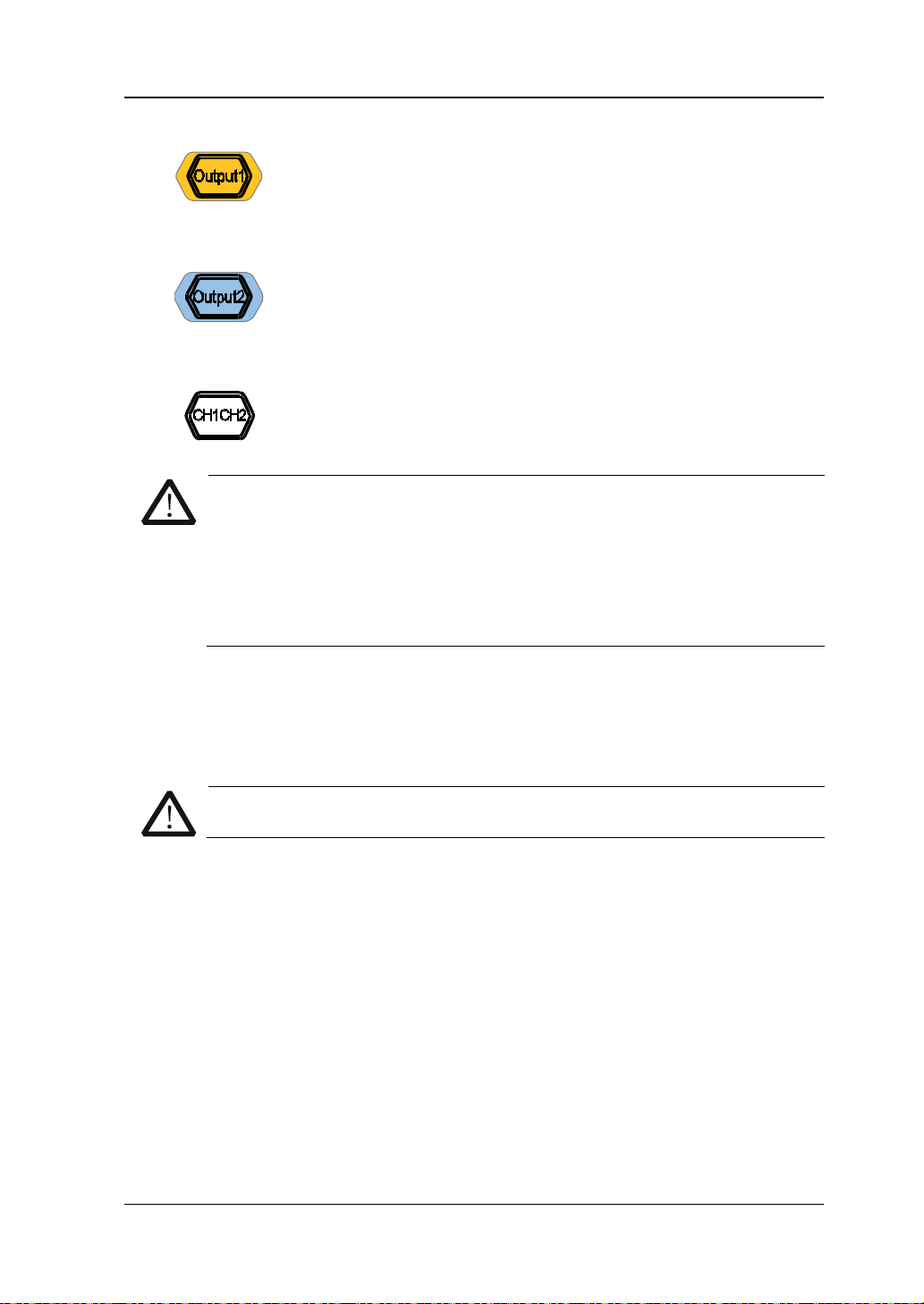
7. 通道控制区
用于控制 CH1 的输出。
— 按下该按键,背灯变亮,打开 CH1 输出。此时,[CH1] 连接
器以当前配置输出信号。
— 再次按下该键,背灯熄灭,此时,关闭 CH1 输出。
用于控制
— 按下该按键,背灯变亮,打开 CH2 输出。此时,[CH2] 连接
器以当前配置输出信号。
的输出。
— 再次按下该键,背灯熄灭,此时,关闭 CH2 输出。
用于切换
为当前选中通道。
CH1 和 CH2 通道输出端设有过压保护功能,满足下列条件之一则产生过
压保护。产生过压保护时,屏幕弹出提示消息,输出关闭。
仪器幅值设置大于 2Vpp或输出偏移大于|2VDC|,输入电压大于
±11.5V±0.1V。
仪器幅值设置小于等于 2Vpp或输出偏移小于等于|2V
|,输入电压
DC
大于±3.5V±0.1V。
8. Counter 测量信号输入连接器
BNC 连接器,输入阻抗为 1MΩ。用于接收频率计测量的被测信号。
9. 频率计
10. 方向键
DG1000Z 快速指南 5
为了避免损坏仪器,输入信号的电压范围不得超过±7Vac+dc。
用于开启或关闭频率计功能。
— 按下该按键,背灯变亮,左侧指示灯闪烁,频率计功能开启。
— 再次按下该键,背灯熄灭,此时,关闭频率计功能。
— 使用旋钮设置参数时,用于移动光标以选择需要编辑的位;
— 使用键盘输入参数时,用于删除光标左边的数字。
— 存储或读取文件时,用于展开或收起当前选中目录。
— 文件名编辑时,用于移动光标选择文件名输入区中指定的字符。
Page 14
RIGOL
1μHz至10MHz
采样率和频率
11. 旋钮
— 使用旋钮设置参数时,用于增大(顺时针)或减小(逆时针)当前光标处的
数值。
— 存储或读取文件时,用于选择文件保存的位置或用于选择需要读取的文件。
— 文件名编辑时,用于选择虚拟键盘中的字符。
— 在 Arb 选择波形 内建波形 中,用于选择所需的内建任意波。
12. 数字键盘
包括数字键(0 至 9)、小数点(.)和符号键(+/-),用于设置参数。
注意:
编辑文件名时,符号键用于切换大小写。
连续按两次小数点可将用户界面以*.Bmp 格式快速保存至 U 盘。
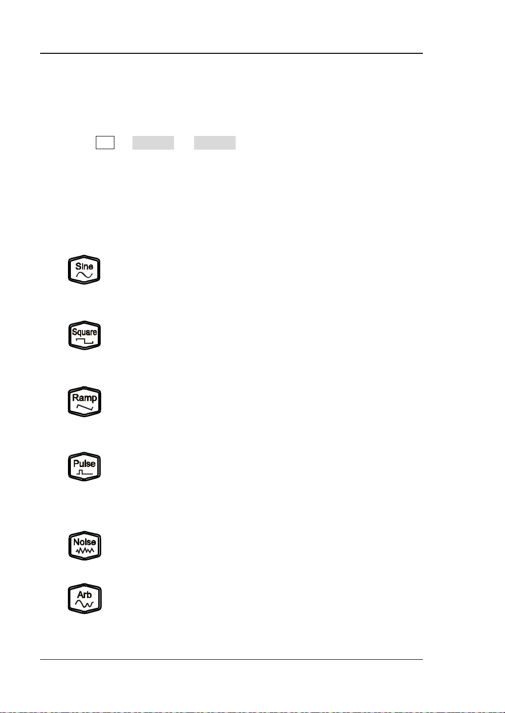
13. 波形键
提供频率从 1μHz 至 60MHz 的正弦波输出。
— 选中该功能时,按键背灯变亮。
— 可以设置正弦波的频率/周期、幅值/高电平、偏移/低电平和
起始相位。
提供频率从 1μHz 至 25MHz 并具有可变占空比的方波输出。
— 选中该功能时,按键背灯变亮。
— 可以设置方波的频率/周期、幅值/高电平、偏移/低电平、占
空比和起始相位。
提供频率从 1μHz 至 1MHz 并具有可变对称性的锯齿波输出。
— 选中该功能时,按键背灯变亮。
— 可以设置锯齿波的频率/周期、幅值/高电平、偏移/低电平、
对称性和起始相位。
提供频率从 1μHz 至 25MHz 并具有可变脉冲宽度和边沿时间的脉
冲波输出。
— 选中该功能时,按键背灯变亮。
— 可以设置脉冲波的频率/周期、幅值/高电平、偏移/低电平、
脉宽/占空比、上升沿、下降沿和起始相位。
提供带宽为 60MHz 的高斯噪声输出。
— 选中该功能时,按键背灯变亮。
— 可以设置噪声的幅值/高电平和偏移/低电平。
提供频率从
— 支持
— 多达 160 种内建波形。
— 选中该功能时,按键背灯变亮。
的任意波输出。
两种输出模式。
6 DG1000Z 快速指南
Page 15
RIGOL
Sweep
注意
— 可设置任意波的频率/周期、幅值/高电平、偏移/低电平和起
始相位。
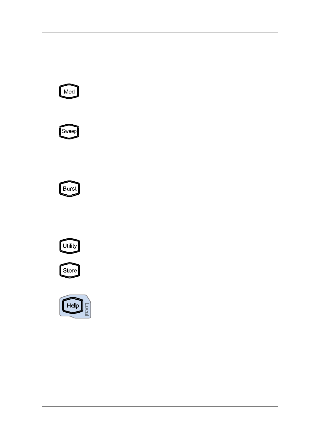
14. 功能键
可输出多种已调制的波形。
— 提供多种调制方式:AM、FM、PM、ASK、FSK、PSK 和 PWM。
— 支持内部和外部调制源。
— 选中该功能时,按键背灯变亮。
可产生正弦波、方波、锯齿波和任意波(DC除外)的
形。
— 支持线性、对数和步进 3 种 Sweep 方式。
— 支持内部、外部和手动 3 种触发源。
波
— 提供频率标记功能,用于控制同步信号的状态。
— 选中该功能时,按键背灯变亮。
可产生正弦波、方波、锯齿波、脉冲波和任意波(DC 除外)的
Burst 波形。
— 支持 N 循环、无限和门控 3 种 Burst 模式。
— 噪声也可用于产生门控 Burst。
— 支持内部、外部和手动 3 种触发源。
— 选中该功能时,按键背灯变亮。
用于设置辅助功能参数和系统参数。选中该功能时,按键背灯变
亮。
可存储或调用仪器状态或者用户编辑的任意波数据。
— 内置一个非易失性存储器(C盘 ),并 可外接一个 U 盘( D 盘 )。
— 选中该功能时,按键背灯变亮。
要获得任何前面板按键或菜单软键的帮助信息,按下该键后,再
按下你所需要获得帮助的按键。
:当仪器工作在远程模式时,该键用于返回本地模式。
15. 菜单软键
与其左侧显示的菜单一一对应,按下该软键激活相应的菜单。
16. LCD 显示屏
3.5 英寸 TFT(320×240)彩色液晶显示屏,显示当前功能的菜单和参数设置、
系统状态以及提示消息等内容,详细信息请参考“
用户界面”一节。
DG1000Z 快速指南 7
Page 16
RIGOL
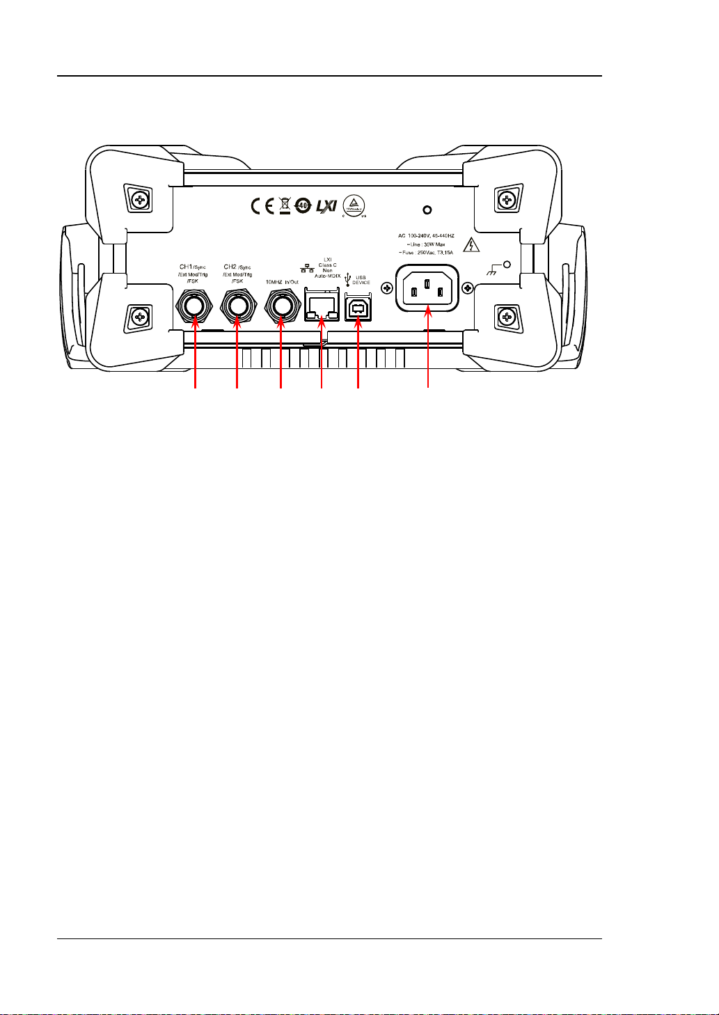
后面板概述
1 2 3 4 5 6
图 2 后面板
1. CH1 同步/外调制/触发连接器:[CH1/Sync/E xt Mod/Trig/F SK]
BNC 母头连接器,标称阻抗为 50Ω,其功能由 CH1 当前的工作模式决定。
— Sync:打开 CH1 输出时,该连接器输出与 CH1 当前配置相匹配的同步信号。
— Ext Mod:若 CH1 开启 AM、FM、PM 或 PWM 并且使用外部调制源,该连
接器接收一个来自外部的调制信号。
— FSK:若 CH1 开启 ASK、FSK 或 PSK 并且使用外部调制源,该连接器接收一
个来自外部的调制信号(可设置该信号的极性)。
— Trig In:若 CH1 开启 Sweep 或 Burst 功能并且使用外部触发源,该连接器
接收一个来自外部的触发信号(可设置该信号的极性)。
— Trig Out:若 CH1 开启 Sweep 或 Burst 功能并且使用内部或手动触发源,
该连接器输出具有指定边沿的触发信号。
有关上述各信号的更多详细信息,请参考本产品用户手册。
2. CH2 同步/外调制/触发连接器:[CH2/Sync/Ext Mod/Trig/FSK]
BNC 母头连接器,标称阻抗为 50Ω,其功能由 CH2 当前的工作模式决定。
— Sync:打开 CH2 输出时,该连接器输出与 CH2 当前配置相匹配的同步信号。
— Ext Mod:若 CH2 开启 AM、FM、PM 或 PWM 且使用外部调制源,该连接
器接收一个来自外部的调制信号。
— FSK:若 CH2 开启 ASK、FSK 或 PSK 且使用外部调制源,该连接器接收一个
来自外部的调制信号(可设置该信号的极性)。
— Trig In:若 CH2 开启 Sweep 或 Burst 功能且使用外部触发源,该连接器接
收一个来自外部的触发信号(可设置该信号的极性)。
Trig Out:若 CH2 开启 Sweep 或 Burst 功能且使用内部或手动触发源,该
连接器输出具有指定边沿的触发信号。
有关上述各信号的更多详细信息,请参考本产品用户手册。
8 DG1000Z 快速指南
Page 17

RIGOL
3. 10MHz 输入/输出连接器:[10MHz In/Out]
BNC 母头连接器,标称阻抗为 50Ω,其功能由仪器使用的时钟类型决定。
— 若仪器使用内部时钟源,该连接器(用作 10MHz Out)可输出由仪器内部晶
振产生的 10MHz 时钟信号。
— 若仪器使用外部时钟源,该连接器(用作 10MHz In)接收一个来自外部的
10MHz 时钟信号。
该连接器通常用于在多台仪器之间建立同步。有关上述各信号的更多详细信息,
请参考本产品用户手册。
4. LAN 接口
用于将信号发生器连接至计算机或计算机所在的网络,进行远程控制。本信号发
生器符合 LXI-C 类仪器标准,可与其他标准设备快速搭建测试系统,轻松实现系
统集成。
5. USB Device 接口
用于与计算机连接,通过上位机软件或用户自定义编程对信号发生器进行控制。
还可与 PictBridge 打印机连接,打印屏幕显示的内容。
6. AC 电源插口
本信号发生器支持的交流电源规格为 100-240V,45-440Hz,最大输入功率不可
超过 30W。电源保险丝规格为 250V,T3.15A。
DG1000Z 快速指南 9
Page 18
RIGOL
注意
开机检查
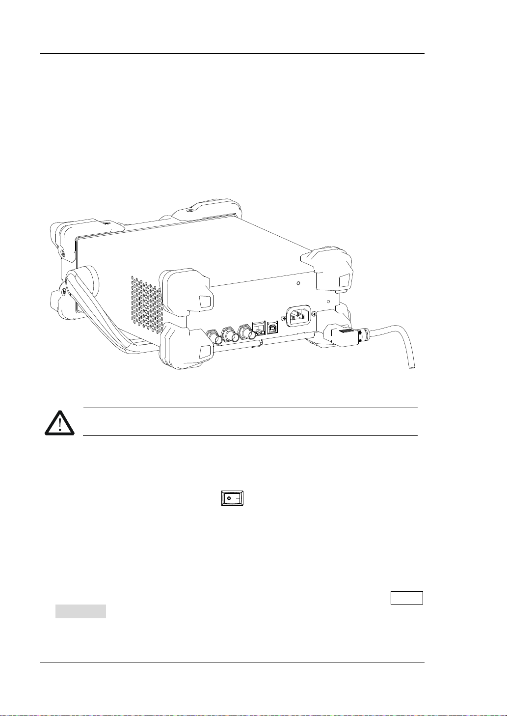
连接电源
请使用附件提供的电源线将信号发生器连接至 AC 电源中,如下图所示。本信号发生
器支持 100-240V,45-440Hz 规格的交流电源。最大输入功率不可超过 30W。当通过
该连接器将信号发生器连接到交流电源时,仪器自动调节至正确的电压范围,无需手
动选择电压范围。
图 3 连接电源
为避免电击,请确保仪器正确接地。
开机
正确连接电源后,按下前面板的电源键
初始化过程和自检过程。结束后,屏幕进入默认界面。如无法正常开机,请参考“
障处理”一节处理。
打开信号发生器。开机过程中仪器执行
故
设置系统语言
DG1000Z 系列函数/任意波形发生器支持中文和英文两种系统语言,您可以按 Utility
Language,选择所需的语言类型。
10 DG1000Z 快速指南
Page 19
RIGOL
7
8
9
10
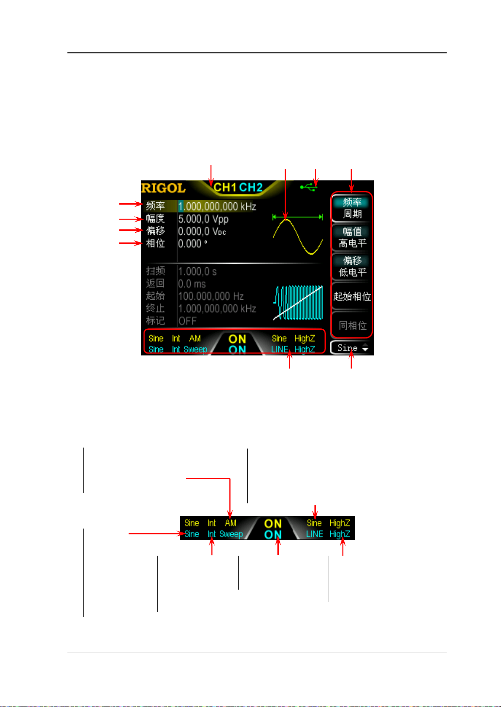
用户界面
DG1000Z 的用户界面包括三种显示模式:
显示。本手册着重以双通道参数显示模式为例介绍仪器的用户界面。
双通道参数模式
6 5 4 3
双通道参数(默认)、双通道图形和单通道
1. 通道输出配置状态栏
显示各通道当前的输出配置。
工作模式:
AM/FM/PM/ASK/FSK/PSK/
Mod (PWM 调制时显示)/
Sweep/Burst
所选波形:
Sine
Squ
Ramp
Pulse
Noise
Arb
Harm
1 2
图 4 用户界面(双通道参数模式)
模拟调制波形:
Sine/Square/Tria/UpRamp/DnRamp/Noise/Arb
数字调制极性:Pos/Neg
Sweep 类型:LINE/LOG/SEG
Burst 类型:Ncycle/INF/Gate
调制源的类型:
Int/Ext
Sweep/Burst 触
发源的类型:
Int/Ext/Mu
通道输出状态:
ON/OFF
输出阻抗的类型:
高阻:显示 HighZ
负载:显示阻值( 默认为
50Ω,范围为 1Ω 至 10kΩ)
DG1000Z 快速指南 11
Page 20

RIGOL
2. 当前功能
显示当前已选中功能的名称。例如:“Sine”表示当前选中正弦波功能,“Edit”
表示当前选中任意波编辑功能。
3. 菜单
显示当前已选中功能对应的操作菜单。
4. 状态栏
:仪器正确连接至局域网时显示。
:仪器工作于远程模式时显示。
:仪器检测到 U 盘时显示。
5. 波形
显示各通道当前选择的波形。
6. 通道状态栏
指示当前通道的选中状态和开关状态。选中 CH1 时,状态栏边框显示黄色;选中
CH2 时,状态栏边框显示蓝色;打开 CH1 时,状态栏 中“ CH1”以黄色高亮显示;
打开 CH2 时,状态栏中“CH2”以蓝色高亮显示。
注意:可以同时打开两个通道,但不可同时选中两个通道。
7. 频率
显示各通道当前波形的频率。按相应的 频率/周期 使“频率”突出显示,通过
数字键盘或旋钮改变该参数。
8. 幅值
显示各通道当前波形的幅值。按相应的 幅值/高电平 使“幅值”突出显示,通
过数字键盘或旋钮改变该参数。
9. 偏移
显示各通道当前波形的直流偏移。按相应的 偏移/低电平 使“偏移”突出显示,
通过数字键盘或旋钮改变该参数。
10. 相位
显示各通道当前波形的相位。按相应的 起始相位 菜单后,通过数字键盘或旋钮
改变该参数。
12 DG1000Z 快速指南
Page 21
RIGOL
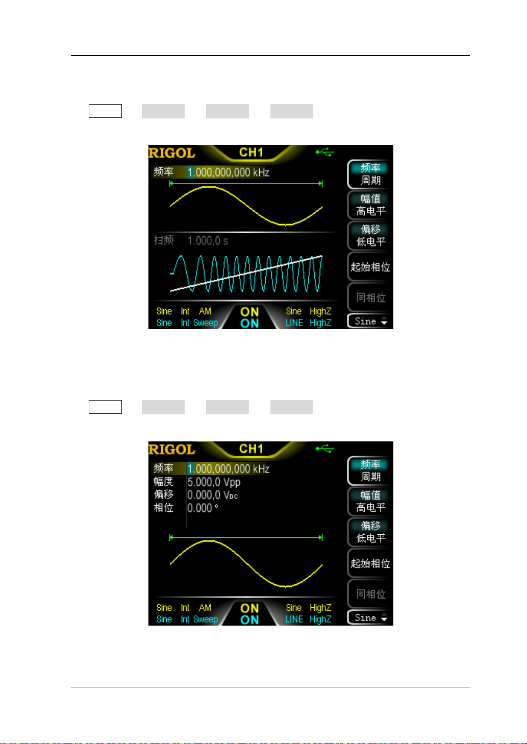
双通道图形模式
按 Utility 系统设置 显示设置 显示模式 选择“双通道图形”即可切换为
双通道图形显示模式,如下图所示。
图 5 用户界面(双通道图形模式)
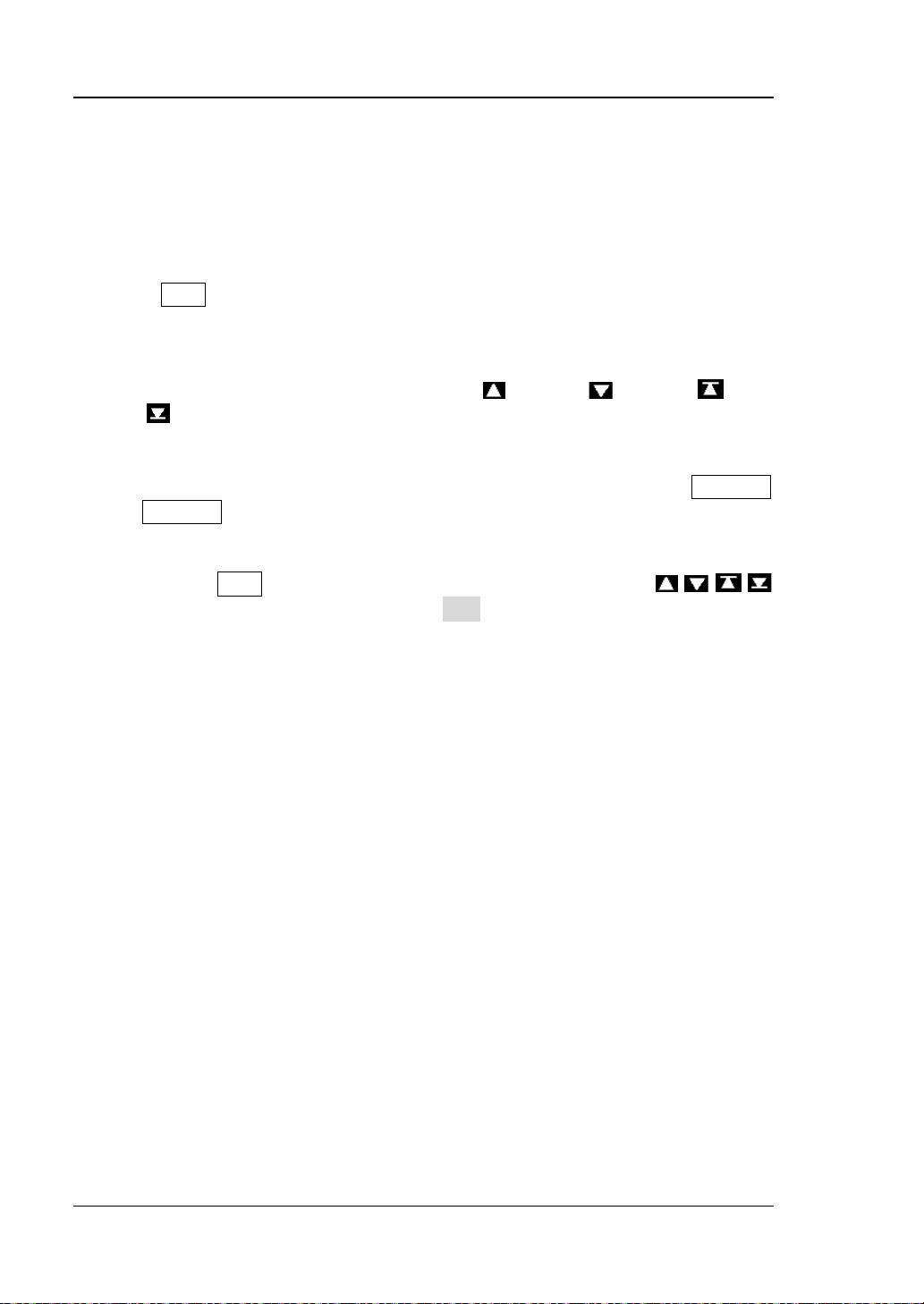
单通道显示模式
按 Utility 系统设置 显示设置 显示模式 选择“单通道显示”即可切换为
单通道显示模式,如下图所示。
图 6 用户界面(单通道显示模式)
DG1000Z 快速指南 13
Page 22
RIGOL
使用内置帮助系统
DG1000Z 内置帮助系统对于前面板上的每个功能按键和菜单软键都提供了帮助信息。
用户可在操作仪器的过程中随时查看任意键的帮助信息。
1. 获取内置帮助的方法
按下 Help 键,背 灯 点亮,然后再按下你所需要获得帮助的功能按键或菜单软键,
仪器界面显示该键的帮助信息。
2. 帮助的翻页操作
当帮助信息为多页显示时,通过菜单软键 (上一行)/ (下一行)/ (上一
页)/
3. 关闭当前的帮助信息
当仪器界面显示帮助信息时,用户按下前面板上的任意功能按键(除 Output1
和 Output2 键外),将关闭当前显示的帮助信息并跳转到相应的功能界面。
4. 常用帮助主题
连续按两次 Help 键打开常用帮助主题列表。此时,您可通过按 / / /
菜单软键或旋转旋钮滚动列表,然后按 选择 选中相应的帮助信息进行查看。
(下一页) 或旋钮可滚动帮助信息页面。
14 DG1000Z 快速指南
Page 23

RIGOL
基本操作
输出基本波形
DG1000Z 可从单通道或同时从双通道输出基本波形,包括正弦波、方波、锯齿波、脉
冲和噪声。本节主要介绍如何从[CH1]连接器输出一个正弦波(频率为 20kHz,幅值
为 2.5Vpp,偏移量为 500mV
1. 选择输出通道
按通道选择键 CH1|CH2 选中 CH1。此时通道状态栏边框以黄色标识。
2. 选择正弦波
按 Sine 选择正弦波,背灯变亮表示功能选中,屏幕右方出现该功能对应的菜单。
3. 设置频率/周期
按 频率/周期 使“频率”突出显示,通过数字键盘输入 20,在弹出的菜单中选
择单位 kHz。
频率范围为 1μHz 至 60MHz。
可选的频率单位有:MHz、kHz、Hz、mHz、μHz。
再次按下此软键切换至周期的设置。
可选的周期单位有:sec、msec、μsec、nsec。
4. 设置幅值
按 幅值/高电平 使“ 幅值”突出显示,通过数字键盘输入 2.5,在弹出的菜单中
选择单位 Vpp。
幅值范围受阻抗和频率/周期设置的限制。
可选的幅值单位有:Vpp、mVpp、Vrms、mVrms、dBm(仅当 Utility 通
道设置 输出设置 阻抗 为非高阻时,dBm 有效)。
再次按下此软键切换至高电平设置。
可选的高电平单位有:V、mV。
5. 设置偏移电压
按 偏移/低电平 使“偏移”突出显示,通过数字键盘输入 500,在弹出的菜单中
选择单位 mV
偏移范围受阻抗和幅值/高电平设置的限制。
可选的偏移单位有:V
再次按下此软键切换至低电平设置。低电平应至少比高电平小 1mV(输出阻
抗为 50Ω 时)。
可选的低电平单位有:V、mV。
6. 设置起始相位
按 起始相位 ,通过数字键盘输入 90,在弹出的菜单中选择单位 º。起始相位值
DC。
DC,起始相位为 90°)。
、mVDC。
DC
DG1000Z 快速指南 15
Page 24

RIGOL
范围为 0º 至 360º。
7. 启用输出
按 Output1 键,背灯变亮,[CH1] 连接器以当前配置输出正弦波信号。
8. 观察输出波形
使用 BNC 连接线将 DG1000Z 的[CH1]与示波器相连接,下图为由示波器观察到
的波形。
图 7 正弦波
16 DG1000Z 快速指南
Page 25

RIGOL
输出任意波
DG1000Z 可从单通道或同时从双通道输出仪器内建或用户自定义的任意波形。本节主
要介绍如何从[CH1]连接器输出一个用户自定义的任意波(点编辑,采样点编辑模式,
循环周期:1s,高 电平 :4V,低电 平 :-2V,初始化点数:8,点 1 至点 4 的电压:4V,
点 5 至点 8 的电压:-2V)。
1. 选择输出通道
按通道选择键 CH1|CH2 选中 CH1。此时通道状态栏边框以黄色标识。
2. 启用任意波功能
按 Arb 键进入任意波设置界面。请先参考“输出基本波形”一章的介绍设置任
意波的频率、幅值、偏移和相位等参数。
3. 编辑任意波
按 Arb 编辑波形 打开任意波编辑菜单。
1) 按 模式 选择“采样点”。
2) 按 循环周期 ,使用数字键盘输入 1,并在弹出的菜单中选择单位 sec。
3) 按 高电平 ,使用数字键盘输入 4,并在弹出的菜单中选择单位 V。
4) 按 低电平 ,使用数字键盘输入-2,并在弹出的菜单中选择单位 V。
5) 按 点数 ,使用数字键盘输入 8后按 确认。此时出现一条-2 V 的电平线。
6) 按 点编辑 ,进入点编辑界面。
按 采样点 ,开始定义第一个点。直接按 电压 软键,使用数字键盘输
入 4,并在弹出的菜单中选择单位 V。
再次按 采样点 ,使用数字键盘或旋钮选择点 2,然后按 电压 ,输入
4V。
使用上述方法输入点 3 至 8 的电压值。
4. 选择波形
按 Arb 选择波形 易失波形 选择已编辑的波形。
5. 启用输出
按 Output1 键,背灯变亮,[CH1]连接器以当前配置输出已编辑的任意波。
6. 观察输出波形
使用 BNC 连接线将 DG1000Z 的 CH1 与示波器相连接,此时,可通过示波器观察
波形。
DG1000Z 快速指南 17
Page 26

RIGOL
输出谐波
DG1000Z 可作为一款谐波发生器,输出具有指定次数、幅值和相位的谐波。本节将介
绍从[CH1]连接器输出 2 次谐波和 4 次谐波,幅值分别为 2Vpp 和 1Vpp,谐波相位分
别为 30°和 50°,谐波次数设为 5。
1. 选择输出通道
按通道选择键 CH1|CH2 选中 CH1。此时通道状态栏边框以黄色标识。
2. 设置基波参数
请参考“输出基本波形”一章的介绍设置基波的频率/周期、幅值/高电平、偏移/
低电平、起始相位等参数。
3. 启用谐波功能
按 Sine 谐波 选择“打开”。按 谐波参数 进入谐波设置菜单。
4. 设置谐波次数
在谐波设置菜单中,按 次数 ,使用数字键盘输入 5,按 确认 。
谐波次数的可设置范围受仪器最大输出频率和当前的基波频率限制。
范围:2 至 仪器最大输出频率÷基波频率,且为整数。最大值为 8。
5. 选择谐波类型
在谐波设置菜单中,按 谐波类型 选择偶次谐波或自定义。
方法一:偶次谐波
按下该软键,仪器输出基波和偶次谐波(2 和 4 次谐波)。
方法二:自定义
按下该软键,用户可自定义输出谐波的次数,最高次数为 8。
使用 8 位二进制数据分别代表 8 次谐波的输出状态,1 表示打开相应次谐波的输
出,0 表示关闭相应次谐波的输出。用户只需使用数字键盘修改各数据位的数值
即可(注意,最左侧的位表示基波,固定为 X,不允许修改)。例 如:将 8 位数据
设置为 X101 0000,表示输出 2 和 4 次谐波。
注意:实际输出的谐波受当前指定的谐波次数和谐波类型共同限制。
6. 设置谐波幅值
在谐波设置菜单中,按 谐波幅值 软键依次设置 2 和 4 次谐波的幅值。
1) 按下 序号 ,使用数字键盘输入 2,按 确认 。
2) 按下 谐波幅值,使用数字键盘输入幅值的数值 2,在弹出的单位菜单中选择
单位 Vpp。
3) 参考步骤 1)和 2)设置 4 次谐波的幅值为 1Vpp。
7. 设置谐波相位
在谐波设置菜单中,按 谐波相位 依次设置 2 和 4 次谐波的相位。
18 DG1000Z 快速指南
Page 27

RIGOL
1) 按下 序号 ,使用数字键盘输入待设置谐波的序号 2,按 确认 。
2) 按下 谐波相位,使用数字键盘输入相位的数值 30,然后在弹出的单位菜单
中选择单位°。
3) 参考步骤 1)和 2)设置 4 次谐波的相位为 50°。
9. 启用输出
按 Output1 键,背灯变亮,[CH1]连接器以当前配置输出基波、2 次和 4 次谐
波。
10. 观察输出波形
使用 BNC 连接线将 DG1000Z 的 CH1 与示波器相连接,下图为由示波器观察到的
波形。
图 8 谐波
输出 AM 已调波形
对于幅度调制(AM),载波的幅度随调制波的瞬时电压而变化。本节介绍从[CH1]连
接器输出一个 AM 已调波形(载波为 5kHz 的正弦波,幅值为 5Vpp;调制波形为 200Hz
的正弦波,调制深度为 80%)。
1. 选择输出通道
按通道选择键 CH1|CH2 选中 CH1。此时通道状态栏边框以黄色标识。
2. 设置载波波形、频率和幅值
1) 载波波形:按 Sine 选择正弦波作为载波波形。
2) 载波频率:按 频率/周期 软键使“频率”突出显示,此时通过数字键盘输
入 5,然后在弹出的菜单中选择单位 kHz。
3) 载波幅值:按 幅值/高电平 软键使“幅值”突出显示,此时通过数字键盘
输入 5,然后在弹出的菜单中选择单位 Vpp。
DG1000Z 快速指南 19
Page 28

RIGOL
3. 选择 AM 调制
按 Mod 类型 AM 键,启用 AM功能。
启用 Mod 时,Sweep 或 Burst 功能将自动关闭(如果当前已打开)。
屏幕下方显示相应配置信息:Int 和 AM。
4. 设置调制波频率
按 调制频率 软键,使用数字键盘输入所需的频率值 200,然后在弹出的单位菜
单中选择所需的单位 Hz。
5. 选择调制波形
按 调制波形 软键,在弹出的波形菜单中选择 Sine。
6. 设置调制深度
按 调制深度 软键,使用数字键盘输入调制深度数值 80,然后在弹出的单位菜单
中选择所需的单位%。
7. 启用输出
按 Output1 键,背灯变亮,[CH1]连接器以当前配置输出 AM 已调制波形。
8. 观察输出波形
使用 BNC 连接线将 DG1000Z 的 CH1 与示波器相连接,下图为由示波器观察到的
波形。
图 9 AM 已调波形
20 DG1000Z 快速指南
Page 29

RIGOL
输出 FSK 已调波形
FSK 调制时,信号发生器在两个预置频率(载波频率和跳频频率)间“移动”其输出
频率。本节将介绍从[CH1]连接器输出一个 FSK 波形(载波为 3kHz 的正弦波,幅值
为 5Vpp;跳跃频率为 500Hz,调制速率为 100Hz,调制极性为正极性)。
1. 选择输出通道
按通道选择键 CH1|CH2 选中 CH1。此时通道状态栏边框以黄色标识。
2. 设置载波波形、频率和幅值
1) 载波波形:按 Sine 选择正弦波作为载波波形。
2) 载波频率:按 频率/周期 软键使“频率”突出显示,此时通过数字键盘输
入 3,然后在弹出的菜单中选择单位 kHz。
3) 载波幅值:按 幅值/高电平 软键使“幅值”突出显示,此时通过数字键盘
输入 5,然后在弹出的菜单中选择单位 Vpp。
3. 选择 FSK 调制
按 Mod 类型 FSK 键,启用 FSK 功能。
启用 Mod 时,Sweep 或 Burst 功能将自动关闭(如果当前已打开)。
屏幕下方显示相应配置信息:Int 和 FSK。
4. 设置跳跃频率
按 跳跃频率 软键,使用数字键盘输入所需的频率值 500,然后在弹出的单位菜
单中选择所需的单位 Hz。
5. 设置调制速率
按 调制速率 软键,使用数字键盘输入所需的频率值 100,然后在弹出的单位菜
单中选择所需的单位 Hz。
6. 设置调制极性
按 极性 软键,选择调制波的正极性控制频率输出。此时,在调制波幅值为逻辑
低电平时输出载波频率,逻辑高电平时输出跳频频率。
7. 启用输出
按 Output1 键,背灯变亮,[CH1]连接器以当前配置输出 FSK 波形。
8. 观察输出波形
使用 BNC 连接线将 DG1000Z 的 CH1 与示波器相连接,此时,可通过示波器观察
波形。
DG1000Z 快速指南 21
Page 30

RIGOL
输出 Sweep 波形
DG1000Z 可从单通道或同时从双通道输出 Sweep 波形。本节介绍如何从[CH1]连接
器输出 Sweep 波形(线性扫描,载波为正弦波,幅值为 5Vpp,频率范围为 50Hz~1kHz,
扫描时间为 1s,内部触发源)。
1. 选择输出通道
按通道选择键 CH1|CH2 选中 CH1。此时通道状态栏边框以黄色标识。
2. 设置 Sweep 的载波波形和幅值
1) 波形:按 Sine 选择正弦波作为载波波形。
2) 幅值:按 幅值/高电平 软 键 使“ 幅值”突出显示,此时通过数字键盘输入 5,
然后在弹出的菜单中选择单位 Vpp。
3. 开启 Sweep 功能
按前面板的 Sweep 键,背灯变亮,表示启用 Sweep 功能。
启用 Sweep 时, Mod 或 Burst 功能将自动关闭(如果当前已打开)。
屏幕下方显示相应配置信息:Int 和 Sweep。
4. 选择扫描类型
按 类型 软键选择线性。此时,界面中的波形上出现一条白色
直线,表示线性扫描类型,如右图所示。
5. 设置起始频率和终止频率
1) 起始频率
按 起始/中心 ,使“起始”突出显示,使用数字键盘输入所需的频率值 50,
然后在弹出的单位菜单中选择单位 Hz。
2) 终止频率
按 终止/跨度 ,使“终止”突出显示,使用数字键盘输入所需的频率值 1,
然后在弹出的单位菜单中选择单位 kHz。
6. 设置扫描时间
按 扫描时间 ,使用数字键盘输入所需的时间值 1,在弹出的菜单中选择单位 sec。
7. 选择触发源
按 触发 触发源 ,选择内部触发源。
9. 启用输出
按 Output1 键,背灯变亮,[CH1]连接器以当前配置输出 Sweep 波形。
10. 观察输出波形
使用 BNC 连接线将 DG1000Z 的 CH1 与示波器相连接,此时,可通过示波器观察
波形。
22 DG1000Z 快速指南
Page 31

RIGOL
输出 Burst 波形
DG1000Z 可从单通道或同时从双通道输出具有指定循环数目的波形(称为 Burst)。 本
节介绍如何从[CH1]连接器输出 Burst 波 形( 3 个循环,载 波 为 正弦波,幅值为 5Vpp,
周期为 1ms,猝发周期为 10ms,内部触发源,延时:1ms)。
1. 选择输出通道
按通道选择键 CH1|CH2 选中 CH1。此时通道状态栏边框以黄色标识。
2. 设置 Burst 的载波波形和幅值
1) 波形:按 Sine 选择正弦波作为载波波形。
2) 幅值:按 幅值/高电平 使“幅值”突出显示,通过数字键盘输入 5,然后在
弹出的菜单中选择单位 Vpp。
3) 周期:按 频率/周期 使“周期”突出显示,通过数字键盘输入 1,然后在弹
出的菜单中选择单位 msec。
3. 开启 Burst 功能
按前面板的 Burst 键,背灯变亮,表示启用 Burst 功能。
启用 Burst 时, Mod 或 Sweep 功能将自动关闭(如果当前已打开)。
屏幕下方显示相应配置信息:Int 和 Burst。
4. 设置 Burst 类型和循环数
按 类型 ,选择 N 循环。屏幕中循环数参数突出显示,处于可编辑状态,此时使
用数字键盘输入循环次数 3,然后按 确认 软键。
5. 设置 Burst 周期
Burst 周期仅适用于 N 循环类型,是 指 从一个 Burst 开始到下一个 Burst 开始的时
间。
按 猝发周期 ,使用数字键盘输入时间值 10,在弹出的菜单中选择单位 msec。
6. 选择 Burst 触发源
按 触发 触发源 ,选择内部触发。
7. 设置延时
延时仅适用于 N 循环和无限脉冲串类型,是指信号发生器从接受到触发信号到开
始输出 N 循环(或无限)脉冲串之间的时间。按 延时,使用数字键盘输入所需
的时间值 1,在弹出的菜单中选择单位 msec。
8. 启用输出
按 Output1 键,背灯变亮,[CH1]连接器以当前配置输出 Burst 波形。
9. 观察输出波形
使用 BNC 连接线将 DG1000Z 的 CH1 与示波器相连接,下图为由示波器观察到的
DG1000Z 快速指南 23
Page 32

RIGOL
波形。
图 10 Burst
远程控制
DG1000Z 支持通过 USB、LAN 或 GPIB(选件)接口与计算机进行通信从而实现远程
控制。远程控制基于 SCPI 命令集(Standard Commands for Programmable
Instruments,用于可编程仪器的标准命令集)实现。本节将介绍如何使用 RIGOL 提
供的通用 PC 软件 Ultra Sigma 发送 SCPI 命令并通过 USB 接口对信号发生器进行远程
控制。有关命令的详细说明请参考本产品的《编程手册》。
当仪器工作在远程模式时,用户界面显示
外)。此时,您可以按 Help 键退出远程模式。
1. 安装 Ultra Sigma 软件
获取Ultra Sigma软件,然后按照指导正确安装软件及所需组件。该软件可从标配
附件的资源光盘中获得,您也可以登录RIGOL网站(
版本的软件。
2. 通过 USB 接口远程控制信号发生器
1) 连接设备
使用 USB 数据线连接信号发生器(USB Device)与计算机(USB Host)。
2) 安装 USB 驱动
本信号发生器为 USB-TMC 设备,将信号发生器与 PC正确连接并且开机后(信
号发生器将自动配置为 USB 接 口 ), PC将弹出硬件更新向导对话框,请按照
向导的提示安装 USB Test and Measurement Device 驱动程序。
3) 搜索设备资源
图标,前面板按键被锁定(Help 除
www.rigol.com)下载最新
24 DG1000Z 快速指南
Page 33

RIGOL
打开 Ultra Sigma,软件将自动搜索当前连接到 PC 上的信号发生器资源,您
也可以点击
进行搜索。
4) 查看设备资源
搜索到的资源将出现在 RIGOL Online Resource 目录下,并且显示仪器的型
号和 USB 接口信息,如图 11 所示:
图 11 查看 USB 仪器资源
5) 通讯测试
右击资源名 DG1062Z (USB0::0x1AB1::0x0642::DG1A000001::INSTR),选
择 SCPI Panel Control,打开远程命令控制面板,即可通过该面板发送命令和
读取数据。
图 12 通过 USB 读写命令
DG1000Z 快速指南 25
Page 34

RIGOL
故障处理
下面列举了 DG1000Z 在使用过程中可能出现的故障及排查方法。当您遇到这些故障
时,请按照相应的步骤进行处理,如不能处理,请与 RIGOL 公司联系,同时请提供
您机器的设备信息(获取方法:Utility 系统信息)。
1. 如果按下电源键信号发生器仍然黑屏,没有任何显示:
1) 检查电源接头是否接好。
2) 检查电源键是否按实。
3) 做完上述检查后,重新启动仪器。
4) 如果仍然无法正常使用本产品,请与 RIGOL 联系。
2. 屏幕显示太暗,看不清:
1) 检查液晶屏的亮度和对比度设置值是否太小。
2) 按 Utility 系统设置 显示设置 ,进入屏幕显示设置菜单,然后分别
按 亮度 和 对比度 软键,使用数字键盘或旋钮调节信号发生器液晶屏的亮
度和对比度至合适的状态。
3. 信号发生器被锁定:
1) 检查信号发生器是否工作在远程控制模式(远程控制时,用户界面状态栏显
示
2) 重新启动信号发生器的电源,也可解除锁定。
4. 设置正确但无波形输出:
1) 检查 BNC 电缆是否与相应的 [CH1] 或 [CH2] 通道输出端口紧固连接。
2) 检查 BNC 线是否有内部损伤。
3) 检查 BNC 线与测试仪器是否紧固连接。
4) 检查 Output1 或 Output2 键背灯是否点亮。如果未点亮,按下相应按键
使其背灯点亮。
5) 做完上述检查后,将 Utility 系统设置 开机设置 设为上次值,然后
重新启动仪器。
6) 如果仍然无法正常使用本产品,请与 RIGOL 联系。
5. U 盘设备不能被识别:
1) 检查 U 盘设备是否连接至其他仪器或计算机上可以正常工作。
2) 确认使用的为 Flash 型 U盘设备,本仪器不支持硬盘型 U 盘设备。
3) 重新启动仪器后,再插入 U 盘设备进行检查。
4) 如果仍然无法正常使用 U 盘,请与 RIGOL 联系。
6. 如何以 dBm 为单位设置波形的幅值?
1) 按 CH1|CH2 键选择所需通道。
2) 检查 Utility 通道设置 输出设置 阻抗 是否为高阻。若是,此时
标志)。按 Help 键可退出远程控制模式,解锁前面板。
26 DG1000Z 快速指南
Page 35

RIGOL
无法以 dBm 为单位设置波形的幅值,请按 阻抗 选择负载并使用数字键盘
或旋钮设置合适的负载值。
3) 选择所需的波形,按 幅值/高电平 使“幅值”突出显示,通过数字键盘输
入所需的数值,在弹出的菜单中选择单位 dBm 即可。
7. 性能校验测试没有通过:
(1) 检查信号源是否在校准周期内(校准周期为1年);
(2) 确认是否在测试之前将信号源预热了至少30分钟;
(3) 检查信号源是否处于规定环境温度下;
(4) 确认测试是否处于强磁环境下进行;
(5) 检查信号源以及测试系统的供电是否有强干扰;
(6) 检查使用的测试设备的性能是否符合要求;
(7) 确保使用的测试设备在校准周期内;
(8) 检查使用的测试设备是否在其手册要求的工作条件下;
(9) 检查所有的连接是否紧固;
(10) 查看所有的线缆是否有内部损伤;
(11) 确保操作符合性能校验手册要求的设置和流程;
(12) 确认误差计算是否有失误;
(13) 正确理解本产品对“典型值”的定义:指产品在特定条件下的性能指标。
DG1000Z 快速指南 27
Page 36

Page 37

RIGOL
Quick Guide
DG1000Z Series Function/Arbitrary
Waveform Generator
Jan 2014
RIGOL Technologies, Inc.
Page 38

Page 39

RIGOL
Guaranty and Declaration
Copyright
© 2013 RIGOL Technologies, Inc. All Rights Reserved.
Trademark Information
RIGOL is a registered trademark of RIGOL Technologies, Inc.
Publication Number
QGB09102-1110
Notices
RIGOL products are protected by patent law in and outside of P.R.C.
RIGOL reserves the right to modify or change parts of or all the specifications and
pricing policies at company’s sole decision.
Information in this publication replaces all previously corre sp onding material.
RIGOL shall not be liable for losses caused by either incidental or consequential in
connection with the furnishing, use or performance of t his manual as well as any
information contained.
Any part of this document is forbidden to be copied or photocopied or rearranged
without prior written approval of RIGOL.
Product Certification
RIGOL guarantees this product conforms to the national and industrial stand ards in
China as well as the ISO9001:2008 standard and the ISO14001:2004 standard. Other
international standard conformance certification is in pr ogr ess.
Contact Us
If you have any problem or requirement when using our products or this manual, please
contact RIGOL.
E-mail: service@rigol.com
Website: www.rigol.com
DG1000Z Quick Guide I
Page 40

RIGOL
Safety Requirement
General Safety Summary
Please review the following safety precautions carefully before putting the instrument
into operation so as to avoid any personal injuries or damages to the instrument and any
product connected to it. To prevent potential hazards, please use the instrument only
specified by this manual.
Use Proper Power Cord.
Only the power cord de signed for the instr ument and authorize d by local cou ntr y could
be used.
Ground The Instrument.
The instrument is grounded through the Protective Earth lead of the power cord. To avoid
electric shock, it is essential to connect the earth terminal of power cord to the Protective
Earth terminal before any inputs or outputs.
Observe All Terminal Ratings.
To avoid fire or shock hazard, observe all ratings and markers on the instrument and
check your manual for more information about ratings before connecting.
Use Proper Overvoltage Protection.
Make sure that no overvolta ge (such as that cause d by a thunderstorm) ca n reach the
product, or else the operator might expose to danger of electrical shock.
Do Not Operate Without Covers.
Do not operate the instrument with covers or panels removed.
Avoid Circuit or Wire Exposure.
Do not touch exposed junctions and components when the unit is powered.
Do Not Operate With Suspected Failures.
If you suspect damage occurs to the instrument, have it inspected by qualified service
personnel before further operations. Any maintenance, adjustment or replacement
especially to circuits or accessories must be performed by RIGOL authorized personnel.
Keep Well Ventilation.
Inadequate ventilation may cause increasing of temperature or damages to the device.
So please keep well ventilated and inspect the intake and fan regularly.
Do Not Operate in Wet Conditions.
In order to avoid short circuiting to the interior of the device or electric shock, please do
not operate in a humid environment.
II DG1000Z Quick Guide
Page 41

RIGOL
WARNING
DANGER
indicates an injury or hazard may immedi ately happen.
WARNING
indicates an injury or hazard may be accessible potentially.
CAUTION
indicates a potential damage to the instrument or other property might
Do Not Operate in an Explosive Atmosphere.
In order to avoid damages to the device or personal injuries, it is important to operate the
device away from an explosive atmosphere.
Keep Product Surfaces Clean and Dry.
To avoid the influence of dust and/or moisture in air, please keep the surface of device
clean and dry.
Electrostatic Prevention.
Operate in an electrostatic discharge protective area environment to avoid damages
induced by static discharges. Always ground both the internal and external conductors of
the cable to release static before connecting.
Handling Sa fety.
Please handle with care during transportation to avoid damages to buttons, knob
interfaces and other parts on the panels.
Safety Terms and Symbols
Terms in this Manual. These terms may appear in this manual:
Warning statements indicate the conditions or practices that could result in
injury or loss of life.
CAUTION
Caution statements indicate the conditions or practices that could result in
damage to this product or other property.
Terms on the Product. These terms may appear on the Product:
occur.
Symbols on the Product. These symbols may appear on the product:
Hazardous
Voltage
Safety
Warning
Protective
Earth
Terminal
Chassis
Ground
DG1000Z Quick Guide III
Test
Ground
Page 42

RIGOL
CAUTION
WARNING
General Care and Cleaning
General Care:
Do not store or le ave the instr ument in where the instrument will be exposed to direct
sunlight for long periods of time.
Cleaning:
Clean the instrument regularly according to its operating conditions. To clean the exterior
surface, perform the following steps:
1. Disconnect the instr ument from all power sources.
2. Clean the loose dust on the outsi de of the ins trum ent wit h a li nt- free cloth (with a
mild detergent or water). When cleaning the LCD, take care to avoid scarifying it.
T o av oid damages to the instru ment, do not expose them to liquids which have
causticity.
To avoid injury resulting from short circuit, make sure the instrument is
completely dry before reconnecting to a power source.
Environmental Consideratio ns
The following symbol indicates that this product complies with the applicable European
Union requirements according to Directive s 2002/96/EC on waste ele c trical and
electronic equipment (WEEE) and batteries.
Product End-of-Life Handling
The equipment may contain substances that could be harmful to the environment or
human health. In order to avoid release of such substances into the environment and
harm to human health, we encourage you to recycle this product in an appropriate
system that will ensure that most of the mat erials are reused or recycled appropriately.
Please contact your local authorities for disp osal or recycling information.
IV DG1000Z Quick Guide
Page 43

RIGOL
Model
Channels
Max. Frequency
DG1032Z
2
30MHz
Document Overview
Format Conventions in this Manual
1. Button
The key at the front panel is denoted by the format of “Text Box + Button Name
(Bold)” in the manual, for example, Sine.
2. Menu:
The menu is denoted by the format of “Character Shading + Menu Word (Bold)” in
the manual, for example, Freq.
3. Connector:
The connector at the front or rear panel is denoted by the format of “Square
Brackets + Connector Name (Bold) in the manual, for example, [Counter].
4. Operation Steps:
The next step of the operation is denoted by an arrow “” in the manual. For
example, Sine Freq denotes pressing Sine at the front panel and then pressing
Freq.
Content Conventions in this Manual
1. DG1000Z series function/arbitrary waveform generator includes DG1032Z and
DG1062Z. In this manual, DG1062Z is taken as an example to illustrate the ba sic
operations of the generator. For more details, please refer to DG1000Z Series
Function/Arbitrary Waveform Generator User’s Guide.
2. All models of DG1000Z series function/arbitrary waveform generator are equipped
Manuals of this Product
The manuals of this product mainly incl ude the quick guide, user’s guide, programming
guide and data shee t. For the newest version of the desired manual, download it
from
DG1000Z Quick Guide V
DG1062Z 2 60MHz
with dual channel s (CH1 and CH2). Unless otherwise specif ied, this manual takes
CH1 as an example to introduce the operation method which is also applied to CH2.
www.rigol.com.
Page 44

RIGOL
Content
Guaranty and Declaration ................................................................................. I
Safety Requirement ........................................................................................ II
General Safety Summary ...................................................................................II
Safety Terms and Symbols ............................................................................... III
General Care and Cleaning ............................................................................... IV
Environmental Considerations ........................................................................... IV
Document Overview ........................................................................................ V
Quick Start ....................................................................................................... 1
General Inspection ............................................................................................ 1
To Adjust the Handle ......................................................................................... 2
Appearance and Dimensions .............................................................................. 3
Front Panel Overview ........................................................................................ 4
Rear Panel Overview ......................................................................................... 9
Power On and Inspection ................................................................................ 11
To Connect to Power ................................................................................ 11
Power-on Inspection ................................................................................ 11
To Set the System Language .................................................................... 11
User Interface ................................................................................................ 12
Dual Channels Parameters M ode ............................................................... 12
Dual Channels Graph Mode ...................................................................... 14
Single Channel Mode ................................................................................ 14
To Use the Built-in Help System ....................................................................... 15
Basic Operations ............................................................................................ 16
To Output Basic Waveform .............................................................................. 16
To Output Arbitrary Waveform ......................................................................... 17
To Output Harmonics ...................................................................................... 19
To Output AM Modulated Waveform ................................................................. 21
To Output FSK Modulated Waveform ................................................................ 22
To Output Sweep Waveform ............................................................................ 23
To Output Burst Waveform .............................................................................. 24
Remote Control .............................................................................................. 26
Troubleshooting ............................................................................................. 28
VI DG1000Z Quick Guide
Page 45

Quick Start
General Inspection
1. Inspect the shipping container for damage
Keep the damaged shipping container or cushioning material until the contents
of the shipment have been checked for completeness and the instrument has
passed both electrical and mechanical tests.
The consigner or carrier shall be liable for the damage to instrument resulting
from shipment. RIGOL would not be re sponsible for free maintenance/rework
or replacement of the unit.
2. Inspect the instrument
In case of any damage, or defect, or failure, notify your RIGOL sales
representative.
3. Check the accessories
Please check the accessories according to the packing lists. If the accessories
are incomplete or damaged, please contact your RIGOL sales representative.
RIGOL
DG1000Z Quick Guide 1
Page 46

RIGOL
To Adjust the Handle
To adjust the handle position of the instrument, please grip the handle by sides and
pull it outward. Then, rotate the handle to the desired position. The operating
method is shown below.
Adjusting the handle
Viewing Positions Car ryin g Position
2 DG1000Z Quick Guide
Page 47

RIGOL
Appearance and Dimensions
Front View Unit: mm
Side View Unit: mm
DG1000Z Quick Guide 3
Page 48

RIGOL
Front Panel Overview
16 15 14 13 12 11 10
1 2 3 4 5 6 7 8 9
Figure 1 Front Panel
1. Power Key
The power key is used to turn the generator on or off.
2. USB Host
The USB Host interface is used to be connected an USB storage device to read
the saved waveform or state files or store the current instrument state and
edited waveform data into the USB storage device. In additional, the content
displayed in the sc reen is also can be saved as a picture file (*.Bmp) in the U SB
storage device.
3. Page Down
This key is used to open the next page of the current menu.
4. Return to the Previous Menu
Quit the current menu and return to the previous menu.
5. CH1 Output Connector
BNC connector. The nominal output impedance is 50Ω.
When the Output1 is enabled (the backlight goes on), this connector outputs
the waveform based on the current settings of CH1.
6. CH2 Output Connector
BNC connector. The nominal output impedance is 50Ω.
When the Output2 is enabled (the backlight goes on), this connector outputs
the waveform based on the current settings of CH2.
4 DG1000Z Quick Guide
Page 49

RIGOL
Press this key to open the output of CH1, the backlight goes
CAUTION
DC
7. Channel Control Area
Used to control the output of CH1.
—
on and the [CH1] connector outputs the waveform based on
the current settings of CH1.
— Press this key again to close the output of CH1 and the
backlight goes off.
Used to control the output of CH2.
— Press this key to open the output of CH2, the backlight goes
on and the [CH2] connector outputs the waveform based on
the current settings of CH2.
— Press this key again to close the output of CH2 and the
backlight goes off.
Used to switch the current selected channel between CH1 and
CH2.
Overvoltage protection of CH1 and CH2 will take effect once any of the
following conditions is met. When overvoltage protection takes effect, a
message will be displayed and the output is disabled.
The input voltage is higher than ±11.5V±0.1V when the amplitude
of the generator is greater than 2Vpp or the DC offset is greater than
|2V
|.
DC
The input voltage is higher than ±3.5V±0.1V when the amplitude of
the generator is lower than or equa l to 2Vpp or the DC offs et is
lower than or equal to |2V
8. Input Connector for the Signal Measured by Counter
BNC connector. The input impedance is 1MΩ. This connector is used to accept
the signal measured by the counter.
Note
To avoid dama ge to the instrument, the input signal voltage cannot
exceed ±7Vac+dc.
9. Counter
Used to turn the counter on or off.
— Press this key to turn the counter on, the backlight goes on and the
indicator at the left of Counter blinks.
— Press this key again to turn the counter off and the backlight goes off.
|.
DG1000Z Quick Guide 5
Page 50

RIGOL
Output Sine with frequency from 1μHz to 60MHz.
10. Direction Keys
— Used to move the cursor to select the digit to be edited when setting
parameter using knob.
— Used to delete the number at the left of the cursor when inputting
parameter using numeric keyboard.
— Used to unfold or fold the selected directory when storing or reading file.
— Used to move the cursor to select the desired character in filename input
area when editing filename.
11. Knob
— Used to increase (clockwise) or decrease (counterclockwise) the value
marked by the cursor when setting parameter using knob.
— Used to select the s torage location when storing a file or used to select the
file to be read when reading file.
— Used to select a character from the virtual ke yboard when editing filename.
— Used to select a desired built-in arbitrary waveform from Arb Select
Wform BuiltIn.
12. N um eric Keyboard
The numeric keyboard consists of number keys (0 t o 9), decimal point (.) and
sign key (+/-) and is used to set the parameters.
Note:
The si gn key is used to switch between uppercase and lowercase inputs.
Press the decimal point twice to save the content displayed in the user
interface in the USB storage device in *.Bmp format.
13. Wa v eform Keys
— The backlight goes on when this function is selected.
— You can set the parameters for sine waveform including
Freq/Period, Ampl/HiLevel, Offset/LoLevel and Start Phase.
Output Square with freque ncy from 1μHz to 25MHz and variable
duty cycle.
— The backlight goes on when this function is selected.
— You can set the parameters for square waveform including
Freq/Period, Ampl/HiLevel, Offset/LoLevel, Duty Cycle and
Start Phase.
Output Ramp with frequency from 1μHz to 1MHz and variable
symmetry.
— The backlight goes on when this function is selected.
— You can set the parameters for ramp waveform including
Freq/Period, Ampl/HiLevel, Offset/LoLevel, Symmetry and
Start Phase.
6 DG1000Z Quick Guide
Page 51

RIGOL
Output Pulse with frequency from 1μHz to 25MHz and variable
You can set the parameter s for pulse including Freq/Period,
Ampl/HiLevel, Offset/LoLev e l, Width/Duty, Leading, Trailing
Output Gaussian Noise with 60MHz bandwidth.
Output multiple types of modulated waveforms.
Output Sweep waveform for Sine, Square, Ramp and Arb
Used to set the auxiliary function parameters and system
pulse width and edge times.
— The backlight goes on when this function is selected.
—
and Start Phase.
— The backlight goes on when this function is selected.
— You can set the parameters for Noise including
Ampl/HiLevel and Offset/LoLevel.
Output Arbitrary wav efor m with fre quency from 1μHz to 10MHz.
— Support two output modes:
Sample Rate and Frequency.
— Up to 160 built-in waveforms.
— The backlight goes on when this function is selected.
— You can set the parameters for Arb waveform including
Freq/Period, Ampl/HiLevel, Offset/LoLevel and Start Phase.
14. Funct ion Keys
— Support multiple modulation types: AM, FM, PM, ASK, FSK,
PSK and PWM.
— Support internal and external modulation sources.
— The backlight goes on when this function is selected.
(except DC).
— 3 Sweep types: Linear, Log and Step.
— 3 types of trigger sources: Internal, External and Manual.
— Provide frequency mark function used to control the status
of the sync s ignal.
— The backlight goes on when this function is selected.
Output Burst waveform for Sine, Square, Ramp, Pulse and Arb
(except DC).
— 3 Burst types: NCycle, Infinite and Gated.
— Noise can also be used to generate gated burst waveform.
— 3 types of trigger sources: Internal, External and Manual.
— The backlight goes on when this function is selected.
parameters. The backlight goes on when this function is
selected.
DG1000Z Quick Guide 7
Page 52

RIGOL
Store or recall the instrument state or the user-defined arbitrary
the instrument is working in remote mode, press
waveform d a ta.
— A nonvolatile memory (C disk) is built in an d an USB stora ge
device (D disk) can be connecte d.
— The backlight goes on when this function is selected.
To get the help information of any front panel key or menu
softkey, pr ess this key and then press the desired key.
Note: when
this key to retur n to l ocal mode.
15. Menu Softkeys
Correspond to the menus at the left and pressing the softkey will activate the
corresponding menu.
16. LCD
3.5 inches TFT (320×240) color LCD display. The current settings and state of
the instrument can be clearly displaye d. F or detailed information , refer to “User
Interface”.
8 DG1000Z Quick Guide
Page 53

RIGOL
Rear Panel Overview
1 2 3 4 5 6
Figure 2 Rear Panel
1. [CH1/Sync/Ext Mod/Trig/FSK]
It is a BNC (female) connector which nominal imped ance is 50Ω. The function of
this connector is determined by the work mode of CH1.
— Sync: when the output of CH1 is enabled, this connector output the
corresponding sync signal.
— Ext Mod: when AM, FM, PM or PWM of CH1 is enabled and external
modulation source is selected, this connector accepts an exter nal
modulation signal.
— FSK: when ASK, FSK or PSK of CH1 is enabled and external modulation
source is selected, this connector accepts an external modulation signal
which polarity can be set by users.
— Trig In: when Sweep or Burst of CH1 is enabled and external trigger
source is selected, this connector accepts an external trigger signal which
polarity can be set by users.
— Trig Out: when Sweep or Burst of CH1 is enabled and internal or manual
trigger source is selected, this connector outputs the trigger signal with
specified edge type.
For more detailed information about the signals mentioned above, please refer
to the User’s Guide.
2. [CH2/Sync/Ext Mod/Trig/FSK]
It is a BNC (female) connector which nominal imped ance is 50Ω. The function of
this connector is determined by the work mode of CH2.
— Sync: when the output of CH2 is enabled, this connector output the
corresponding sync signal.
— Ext Mod: when AM, FM, PM or PWM of CH2 is enabled and external
DG1000Z Quick Guide 9
Page 54

RIGOL
modulation source is selected, this connector accepts an external
modulation signal.
— FSK: when ASK, FSK or PSK of CH2 is enabled and external modulation
source is selected, this connector accepts an external modulation signal
which polarity can be set by users.
— Trig In: when Sweep or Burst of CH2 is enabled and external trigger
source is selected, this connector accepts an external trigger signal which
polarity can be set by users.
— Trig Out: when Sweep or Burst of CH2 is enabled and internal or manual
trigger source is selected, this connector outputs the trigger signal with
specified edge type.
For more detailed information about the signals mentioned above, please refer
to the User’s Guide.
3. [10MHz In/Out]
It is a BNC (female) conne ctor which nominal i mpedance is 50Ω. The function of
this connector is determined by the type of the clock source.
— When internal clock s ou rce is selecte d, this conne ct or (used as 10MH z Out )
outputs the 10MHz clock signal generated by the internal crystal oscillator
inside the generator.
— When external clock source is selected, this connector (used as 10MHz In)
accepts an external 10MHz clock signal.
This connector is typically used to synchronize multiple generators. For more
detailed information about the signals mentioned above , please refer to the
User’s Guide.
4. LAN Interface
Through this interfa ce, the gener ator can be conne cted to y our computer or the
network of y ou r c om pute r f or rem ote control . An integ rat ed testi ng syst em ma y
be built, as the generator conforms to the LXI-C class standard of LAN-based
instrument control.
5. USB Device Interface
This interface is used to connect a computer which can control the generator
remotely using PC software or by programming. It is also connected to a
PictBridge printer to print the content displayed in the screen.
6. AC Power Socket
The AC power supply specification of this signal generator is 100-240V,
45-440Hz. The maximum input power of the instrument cannot exceed 30W.
The specification of the fuse is 250V, T3.15A.
10 DG1000Z Quick Guide
Page 55

RIGOL
CAUTION
Power On and Inspection
To Connect to Power
Please connect the generator to AC power supply using the power cord supplied in
the accessories as shown in the figure below. The AC power supply specification of
this generator is 100-240V, 45-440Hz. The maximum input power of the instrument
cannot exceed 30W. When the signal generator is connected t o AC power supply via
this connector, the instrument select the correct voltage range automatically and
users do not need to select the voltage range manually.
Figure 3 Connect to Power
To avoid electric shock, make sure that the instrument is correctly
grounded.
Power-on Inspection
After the power sup ply is correctly connected, press the power key
panel to turn on the generator. During the start-up, the instrument performs
initialization and self-test. After that, the instrument enters the default interface. If
the instrument does not start normally, please refer to the “Troubleshooting”.
at the front
To Set the Syste m L anguage
DG1000Z series function/arbitrary generator supports Chinese and English system
languages. You can press Utility Language to switch the system language.
DG1000Z Quick Guide 11
Page 56

RIGOL
7 8 9
10
Channel Output State:
Selected
Work Mode:
User Interface
The user interface of DG1000Z provides three types of display modes: Dual
Channels Parameters (default), Dual C hannels Graph and Single Channel.
This manual mainly introduces the user interface taking the first display mode as an
example.
Dual Channels Parame ters Mode
6 5 4 3
Figure 4 User Interface (Dual Channels Parameters Mode)
1. Channel Output Configuration St atus Ba r
Display the output configurations of the two channels.
AM/FM/PM/ASK/FSK/PSK/
Mod (Displayed when PWM
is enabled)/Sweep/ B u r s t
Waveform:
Sine
Squ
Ramp
Pulse
Noise
Arb
Harm
Type of Modulation
Source: Int/Ext
T ype of Sweep/Burst
Trig Source:
Int/Ext/Mu
1 2
Modulation Waveform of Analog Modul ation:
Sine/Square/Tria/UpRamp/DnRamp/Noise/Arb
Polarity of Digital Modulation: Pos/Neg
Type of Sweep: LINE/LOG/SEG
Type of Burst: Ncycle/INF/Gate
Type of Output Impedance:
High Impedance: display HighZ
Load: display impedance value
(the default is 50Ω and the
range is 1Ω-10kΩ)
12 DG1000Z Quick Guide
Page 57

RIGOL
2. Current Function
Display the function name selected currently. For example, “Sine” is displayed
when the sine is selected and “Edit” is displayed when th e arbitrary waveform
editing function is selected.
3. Menu
Display the operation menu of the function sel ected currently.
4. Status Bar
: Displayed when the instrument is connected to the LAN correctly.
: Displayed when the instrument is in remote mode.
: Displayed when an USB storage device is detected.
5. Waveform
Displayed the waveform currently selected by each channel.
6. Channel Status Bar
Used to indicating the selected status and on/off status of the channels. When
CH1 is selected, the border of the bar is displayed in yellow. When CH2 is
selected, the border of the bar is displayed in blue. When the output of CH1 is
enabled, the “CH1” in the bar is hi ghlighted in y ellow . When t he output of CH2 is
enabled, the “CH2” in the bar is highlighted in blue.
Note: you can e nable the outputs o f the tw o channe ls but y ou cannot sele ct th e
two channels at the same time.
7. Frequency
Display the wav eform frequency of the channel. Press Freq/Period to hi ghlight
“Freq” and use the numeric keyboard or knob to modify this parameter.
8. Amplitude
Display the waveform amplitude of the channel. Press Ampl/HiLevel to
highlight “Ampl” and use the numeric keyboard or knob to modify this
parameter.
9. Offset
Display the waveform DC offset of the channel. Press Offset/LoLevel to
highlight “Offset” and use the numeric keyboard or knob to modify this
parameter.
10. Phase
Display the waveform start phase of the channel. Press Start Phase and u se
the numeric keyboard or knob to modify this parameter.
DG1000Z Quick Guide 13
Page 58

RIGOL
Dual Channels Graph Mode
Press Utility System Display DispMode to select “Dual Graph”, as shown
in the figure below.
Figure 5 User Interface ( Dual Channels Graph Mode)
Single Channel Mode
Press Utility System Display DispMode to select “Single View”, as shown
in the figure below.
Figure 6 User Interf ace (Single Channel Mode)
14 DG1000Z Quick Guide
Page 59

RIGOL
To Use the Built-in Help System
The built-in help system of DG1000Z provides help information for each key and
menu softkey at the fr ont panel. Users can view the help of any key when operating
the instrument.
1. Acquire the built-in h elp
Press Help and the backlight goes on. Then press the desired key or menu
softkey and the corresponding help information is displayed.
2. Page up/down
When the help information is displa yed on multiple pages, use rs can a cquire the
help information on the previous or next page using
line)/
3. Turn off the current help information
When the help information is displayed in the interface, pressing any function
key (except Output1 and Output2) at the front panel will turn off the help
information currently display ed.
4. Main Help Top ic s
Press Help twice to open the list of main help topi cs. Use
knob to select the desi red help topic an d press Select to view the corres pondin g
help information.
(the next line)/ (page up)/ (page down) or the knob.
(the previous
/ / / or the
DG1000Z Quick Guide 15
Page 60

RIGOL
Basic Operations
To Output Basic Waveform
DG1000Z can output basic waveforms (Sine, Square, Ramp, Pulse and Noise) from
one of the channels separately or from the two channels at the same time. This
section introduces how to output a sine waveform (Frequency: 20kHz, Amplitude:
2.5Vpp, DC O ffs et: 500mV
1. To select output channel
Press CH1|CH2 to select CH1. Now the boarder of the channel status bar is
displayed in yellow.
2. To select the Sine
Press Sine to select the sine waveform. The backlight goes on and the
corresponding menu is displayed in the right of the screen.
3. To set the frequency/period
Press Freq/Period to highlight “Freq”, and then use the numeric keyboard to
input 20. Then select kHz from the pop-up menu.
The frequency ranges from 1μHz to 60MHz.
The frequency units available are MHz, kHz, Hz, mHz and μHz.
Press this softkey again to switch to period setting.
The period units available are sec, msec, μsec and nsec.
4. To set the amplitude
Press Ampl/HiLevel to highlight “Ampl”, and use the numeric keyboard to
input 2.5. Then, select Vpp from the pop-up menu.
The amplitude range is limited by the impedance and frequency/period.
The amplitude units available are Vpp, mVpp, Vrms, mVrms and dBm (dBm
is only valid when the setting in Utility Channel Set Output Set
Imped is not HighZ).
Press this softkey again to switch to high level setting.
The high level units available are V and mV.
5. To set the offset
Press Offset/LoLevel to highlight “Offset”, and then use the nume ric k eyboard
to input 500. Then, select mV
The range of the offset is limited by the impedance and frequency/period.
The DC offset voltage units available are V
Press this softkey again to switch to low le vel setting . The low level must be
lower than the high l evel a t least 1mV (when the output impedance is 50Ω).
The low level units available are V and mV.
DC, Start Ph ase: 90°) from the [CH1] connector.
DC from the pop-up menu.
and mVDC.
DC
16 DG1000Z Quick Guide
Page 61

RIGOL
6. To set the start phase
Press Start Phase, and then use the numeric keyboard to input 90. Then,
select ° from the pop-up menu. The start phase ranges from 0° to 360°.
7. To enable the output
Press Output1 to turn CH1 output on. At this point, the backlight goes on and
the [CH1] connector outputs waveform with the specified parameters.
8. To observe the output waveform
Connect the [CH1] connector to the oscilloscope using BNC cable. The
waveform is as shown in the figure below.
Figure 7 Sine
To Output Arbitrary Waveform
DG1000Z can output the built-in or user-defined arbitrary waveforms from a single
channel or from two channels at the same time. This section introduces how to
output an arbitrary waveform from the [CH1] connector (Edit P oints, Sample editin g
mode, Cycle Period: 1s, HiLevel: 4V, LoLevel: -2V, Points: 8, V ol t age of Point#1 to
Point#4: 4V; Voltage of Point#5 to Point#8: -2V).
1. To select output channel
Press CH1|CH2 to sel ect CH1. Now the boarder of the channel status bar is
displayed in yellow.
2. To enable arbitrary waveform
Press Arb to enter the arbitrary waveform setting interface. Please set the
frequency, amplitude, offset and start phase of the arbitrary waveform
according to “
To Output Basic Waveform”.
DG1000Z Quick Guide 17
Page 62

RIGOL
3. To edit arbitrary waveform
Press Arb Edit Wform to open the arbitrary waveform editing menu.
1) Press Mode to select “Sample”.
2) Press Cycle Period, use the numer ic keyboard to input 1 and sel ect sec
from the po p -up menu.
3) Press HiLevel, use the numeric keyboard to input 4 and select V from th e
pop-up menu.
4) Press LoLevel, use the numeric ke yboa rd to in put -2 and select V from the
pop-up menu.
5) Press Points, use the numeric keyboard to input 8 and press Sure. At this
point, a -2V level line appears.
6) Press Edit Points to enter the points editing interface.
Press Sample to define the first point. Press Voltage, use the
numeric keyboard to input 4 and select V from the pop-up menu.
Press Sample again, use the numeric keyb oard or knob to select point
2; then press Voltage to input 4V.
Define the voltage of point 3 to point 8 according to t h e me thod
mentioned above.
4. To select waveform
Press Arb Select Wform Volatile Wfor m to select the waveform edited.
5. To enable the output
Press Output1 to turn CH1 output on. At this point, the backlight goes on and
the [CH1] connector outputs ar bitrary wa veform wit h the specified parameters.
6. To observe the output waveform
Connect the [CH1] connector to the oscilloscope using BNC ca ble. Now , you ca n
observe the waveform via the oscilloscope.
18 DG1000Z Quick Guide
Page 63

RIGOL
To Output Harmonics
DG1000Z can be used as a harmonic generator to output harmonic with specified
order, amplitude and phase. This section introduces how to output the 2
harmonics from the [CH1] connector (Amplitude: 2Vpp and 1Vpp, Pha se : 30 ° and
50°, Order: 5).
1. To select output channel
Press CH1|CH2 to select CH1. Now the boarder of the channel status bar is
displayed in yellow.
2. To set the parameters of the fundamental waveform
Set the frequency/period, amplitude/high level, offset/low level and start phase
of the fundamental waveform according to “To Output Basic Wavef orm”.
3. To enable the harmonic function
Press Sine Harm to select “On”. Press Harmonic Para to enter the
harmonic setting menu.
4. To set harmonic order
Press Order in the harmo nic set ting menu, use the numeric k eyboar d to in put 5
and press Sure.
The range is li mited by the maximum output frequency of the instrument as
well as the fundamental waveform frequency.
Range: integers within 2 to maximum output frequency of the
instrument ÷ fundamental waveform frequency. The maximum is 8.
5. To select harmonic type
Press Type in the harmonic setting menu to select Even or User.
Method 1: Even
Press this key and the instrument would output fundamental waveform and
even harmonics (the 2
nd
and 4th harmonics).
Method 2: User
Press this key and the instrument would output the user-defined orders of
harmonics. The highest order is 8.
8 bits binary data is used to represent the output status of the 8 orders of
harmonics respectively, wherein, 1 represents enabling the output of the
corresponding harmonic and 0 represents disabling t he output of the
corresponding harmonic. Users only need to use the numeric keyboard to
modify the value of each data bit (note: the leftmost bit representing
fundamental waveform is always X and cannot be modified). For example, set
the 8 bits data to X101 0000, thus 2
nd
and 4th orders of harmonics are output.
Note: the actual harmonics output is determined by the “Order” and “Type”
currently specified.
nd
and 4th
DG1000Z Quick Guide 19
Page 64

RIGOL
6. To set harmonic amplitude
Press Harmonic Ampl in the harmonic set ting menu to set the am plitude of the
nd
and 4th harmonics.
2
1) Press SN, use the numeric keyboard to input 2 and press Sure.
2) Press Harmonic Ampl, use the numeric keyboard to input 2 and select
Vpp from the pop-up menu.
3) Set the amplitude of the 4th harmonic to 1Vpp according to 1) and 2).
7. To set harmonic phase
Press Ha rmonic Phase in the harmonic setting menu to set the pha se of the
nd
and 4th harmonics.
2
1) Press SN, use the numeric keyboard to input 2 and press Sure.
2) Press Harmonic Phase, use the nu meric keyboar d to input 30 and s elect °
from the pop-up menu.
3) Set the phase of the 4th harmonic to 50° according to 1) and 2).
9. To enable the output
Press Output1 to turn CH1 output on. At this point, the backlight goes on and
the [CH1] connector outputs the fundamental waveform as well as the 2nd and
th
harmonics.
4
10. To observe the output waveform
Connect the [CH1] connector to the oscilloscope using BNC cable. The
waveform is as shown in Figure 9.
Figure 8 Harmonics
20 DG1000Z Quick Guide
Page 65

RIGOL
To Output AM Modulated Waveform
For amplitude modulation (AM), the amplitude of the carrier waveform varies with
the instantaneous voltage of the mo dulati ng waveform. This section introduces ho w
to output AM modulated waveform from the [CH1] connector (the carrier is sine
with 5kH z frequency a nd 5Vpp amplitude, the modulating waveform is sine with
200Hz frequency and the modulation depth is 80%).
1. To select output channel
Press CH1|CH2 to select CH1. Now the boarder of the channel status bar is
displayed in yellow.
2. To set the carrier waveform shape, frequency and amplitude
1) Carrier Wa veform Shape: press Sine to select sine as t he carrier wa veform.
2) Carrier Frequency: press Freq/Period to highlight “Freq”. At this point, use
the numeric keyboard to input 5. Then, select kHz from the pop-up menu.
3) Carrier Amplitude: press Ampl/HiLevel to highlight “Ampl”, and then use
the numeric keyboard to input 5. Then, select Vpp from the pop-up men u.
3. To select AM modulation
Press Mod Type AM to enable AM function.
When Mod is enabled, Sweep or Burst will be disabled automatically (if
enabled currently).
Int and AM will be displayed in the bottom of the screen.
4. To set Modulating waveform frequency
Press AM F req, and then us e the numeric keyboard to input 200. Then, select
Hz from the pop-up menu.
5. To select modulating waveform
Press Shape to select Sine from the pop-up menu.
6. To set modulation depth
Press AM Depth, and then use the numeric keyboard to input 80. Then,
select % from the pop-up menu.
7. To enable the output
Press Output1 to turn CH1 ou tput o n. At thi s po int, the backlight goes on and
the [CH1] conne ctor outputs t he AM modulated wa vef orm based o n the cur rent
settings.
8. To observe the output waveform
Connect the [CH1] connector to the oscilloscope using BNC cable. The
waveform is as shown in the figure below.
DG1000Z Quick Guide 21
Page 66

RIGOL
Figure 9 AM Modulated Waveform
To Output FSK Modulated Waveform
For FSK (Frequency Shift Keying) modulation, the generat o r “shifts” its output
frequency between two preset frequencies (carrier frequency and hop frequency).
This section introduces how to output FSK modulated waveform from the [CH1]
connector (the carrier is sine with 3kHz frequency and 5Vpp amplitude, the hop
frequency is 500Hz, the FSK rate is 100Hz and the modulating polarity is Pos).
1. To select output channel
Press CH1|CH2 to select CH1. Now the boarder of the channel status bar is
displayed in yellow.
2. To set the carrier waveform shape, frequency and amplitude
1) Carrier Wa veform Shape: press Sine to select sine as t he carrier wa veform.
2) Carrier Frequency: press Freq/Period to highlight “Freq”. At this point, use
the numeric keyboard to input 3. Then, select kHz from the pop-up menu.
3) Carrier Amplitude: press Ampl/HiLevel to highlight “Ampl”, and then use
the numeric keyboard to input 5. Then, select Vpp from the pop-up menu.
3. To select FSK modulation
Press Mod Type FSK to enable FSK funct i on.
When Mod is enabled, Sweep or Burst will be automatically disabled (if
enabled currently).
Int and FSK will be displayed in the bottom of the screen.
4. To set hop frequency
Press Hop Freq, use the numeric key board to in put 500 an d select H z f rom th e
pop-up menu.
22 DG1000Z Quick Guide
Page 67

RIGOL
5. To set FSK rate
Press FSK Rate, use the numeric key board to in put 100 and s elect H z fr om th e
pop-up menu.
6. To set modulating polarity
Press Polarity to select the Pos polarity of the modulating wave f or m to cont r ol
the output frequency. At this point, the generator would output the carrier
frequency when the modulating waveform is logic low and output the hop
frequency when the modulating waveform is logic high.
7. To enable the output
Press Output1 to turn CH1 output on. At this point, the backlight goes on and
the [CH1] connector outputs the FSK modulated waveform based on the
current settings.
8. To observe the output waveform
Connect the [CH1] connector t o the os cilloscope using BNC cable. N ow, you ca n
observe the waveform via the oscilloscope.
To Output Sweep Waveform
DG1000Z can output sweep waveform f rom a single channel or from dual channels at
the same time. This section introduces how to output sweep waveform from the
[CH1] connector (Linear sweep type, the carrier is sine with 5Vpp amplitude, the
frequency range is 50Hz~1kHz, Sweep Time: 1s, Internal trigger source).
1. To select output channel
Press CH1|CH2 to select CH1. Now the boarder of the channel status bar is
displayed in yellow.
2. To set the carrier waveform shape and amplitude for sweep
1) Waveform: Press Sine to select sine as the carrier waveform.
2) Amplitude: Press Ampl/HiLevel to highlight “Ampl”, and then use the
numer ic keyboard to inp ut 5. Then, select Vpp from the pop-up menu.
3. To enable sweep function
Press Sweep to enable the sweep function (the backlight of the key goes on).
When Sweep is enabled, Mod or Burst function will be automatically
disabled (if currently enabled).
Int and Sweep will be displayed in the bottom of the screen.
4. To select sweep type
Press Type to select Linea r. At this p oint, a white lin e a ppears
on the waveform in the screen as shown in the right figure.
DG1000Z Quick Guide 23
Page 68

RIGOL
5. To set the start frequency and stop frequency
1) Start Frequency
Press Start/Center to highlight “Start”, and then use the numeric
keyboard to inpu t “50”. Then, select Hz from the pop-up menu.
2) Stop Frequency
Press Stop/Span to highlight “Stop”, and then use the numeric keyboard
to input 1. Then, select Hz from the pop-up menu.
6. To set the sweep time
Press Sweep Time to input 1 using the numeric keyboard and select sec from
the pop-up menu.
7. To select the trigger source
Press Trigger Source to select Int trigger source.
9. To enable the output
Press Output1 to turn CH1 ou tput o n. At this point, the backlight goes on and
the [CH1] connector outputs the sweep waveform based on the current
settings.
10. To observe the output waveform
Connect the [CH1] connector t o the os cilloscope using BNC cable. Now , y ou can
observe the waveform via the oscilloscope.
To Output Burst Waveform
DG1000Z can output wa vef orm with specified number of cycles (called burst) from a
single channel or from dual channels at the same time. This section introduces how
to output burst from the [CH1] connector (3 cycles, the carrier is sine with 5Vpp
amplitude and 1ms period , Burst P eriod: 10 ms, Inte rnal trig ger sou rce, Delay: 1ms).
1. To select output channel
Press CH1|CH2 to select CH1. Now the boarder of the channel status bar is
displayed in yellow.
2. To set the carrier waveform shape and amplitude for burst
1) Waveform: Press Sine to select sine as the carrier waveform.
2) Amplitude: Press Ampl/HiLevel to highlight “Ampl”, and then use the
numeric keyboard to input 5. Then, select Vpp from the pop-up menu.
3) Period: Press Freq/Period to highlight “Period”, and then use t he numeric
keyboard to inpu t 1. Then, select msec from the pop-up menu.
3. To enable burst function
Press Burst to enable the burst function (the backlight of the key goes on).
When Burst is enabled, Mod or Sweep function will be automatically
24 DG1000Z Quick Guide
Page 69

RIGOL
disabled (if currently enabled).
Int and Burst will be displayed in the bottom of the screen.
4. To set the burst type and Cycles
Press Type to select NCycle . At this point, the Cycles in the screen is highlighted
and can be edited. Use the numeric keybo ar d to input 3 and pres s Sure.
5. To set burst period
Burst period is only available for N cycle burst in internal trigger and is defined
as the time from the start of a burst to the start of the next burst.
Press Burst Period to input 10 using the numeric keyboard and select msec
from the pop-up menu.
6. To select burst trigger source
Press Trigger Source to select Int trigg e r s ource.
7. To set the delay
Burst delay is only available for N cycle and infinite burst type. It is defined as
the time from when the generator receives the trigger signal to starts to output
the N Cycle (or Infinite) burst. Press Delay, and then use the numeric ke yboar d
to input 1. Then select msec from the pop-up menu.
8. To enable the output
Press Output1 to turn CH1 output on. At this point, the backlight goes on and
the [CH1] connector outputs the burst waveform based on the current settings.
9. To observe the output waveform
Connect the [CH1] connector to the oscilloscope using BNC cable. The
waveform is as shown in the figure below.
Figure 10 Burst
DG1000Z Quick Guide 25
Page 70

RIGOL
Remote Control
DG1000Z can communicate with PC through the USB, LAN or GPIB (option ) inte rface
to realize remote control on the basis of the SCPI commands (Standard Commands
for Programmable Instruments). This section introduces how to control the
generator remotely by sending the SCPI commands us ing U l tra Sigma provided by
RIGOL via the USB interface. For detailed information about the c om mands, please
refer to the Programming Guide .
When the instrument is working in remote mode, the
the screen and the keys (exc ept Help ) at the front panel are locked. Now you can
return the instrument to local mode by pressing Help.
1. To install Ultra Sigma
Acquire the Ultra Sigma software and install it as well as its components
according to the instructions. This software is contained in the resource CD in
the standard accessories. You can also download the latest version of the
software from
2. To control the gener at or via USB
1) Connect the device
Connect the generator (USB Device) and PC (USB Host) using USB cable.
2) Install USB drive
This generator is USB-TMC device and the New Hardware Wizard will be
displayed after the generator is correctly connected to the PC (the
generator will be automatically configured to USB interface) and both of
them are started. Please install the “USB Test and Measurement Device”
drive program according to the instructions.
3) Search for device resource
Start Ultra Sigma and the software will search for the generator resource
currently connected to the PC automatically. You can also click
4) View device resource
The resource found together with the instrument model and USB interface
information will be displayed under the “RIGOL Online Resource” directory,
as shown in Figure 12.
www.rigol.com.
to search for the resource manually.
indicator is displayed in
26 DG1000Z Quick Guide
Page 71

RIGOL
Figure 11 To View USB Instrument Resource
5) Communication test
Right-click the resource name DG1062Z
(USB0::0x1AB1::0x0642::DG1A000001::INSTR) and select SCPI Panel
Control to o pen the remot e command control panel through which you can
send commands and read data.
Figure 12 Send and Read Commands via USB
DG1000Z Quick Guide 27
Page 72

RIGOL
Troubleshooting
The commonly encountered failures and their solutions are listed below. When you
encounter those problems, please solve them following the corresponding steps. If
the problem remains still, please contact RIGOL and provide your device
information (Utility System Info).
1. The screen of the generator is still dark (no display) after pressing the
power key:
1) Check whether the power is correctly connected.
2) Check whether the power key is really pressed.
3) Restart the instrument after finishing the above inspections.
4) If it still does not work correctly, please contact RIGOL.
2. The screen is too dark and cannot be seen clearly:
1) Check whether the brightness setting of the LCD screen is too low.
2) Press Utility System Display to enter the display setting menu.
Press Bright and Contrast and use the numeric keyboard or the knob to
adjust the brightness and contrast of the LCD screen to a proper value
respectively.
3. The generator is locked:
1) Check whether the generator is in rem ote control mode (in remote control,
is displayed in the status bar of the use r interface). Pressing Help can
exit the remote control mode and unlock the front panel.
2) Restarting the generator can also unlock the instrument.
4. The settings are correct but no waveform is generated:
1) Check if the BNC cable is t ightly conne cted to the correspondin g [Output1]
or [Output2] connector.
2) Check whether the connecting wire has internal damage.
3) Check whether the BNC cable is tightly connected to the test instrument.
4) Check whether the backlight of Output1 or Output2 goes on. If not,
press corresponding key to illuminate the backlight.
5) Press Utility System Power On to select Last and then restart the
instrument after finishing the above inspections.
6) If it does not work correctly, please contact RIGOL.
5. The USB storage device cannot be recognized:
1) Check whether the USB storage device can work normally when connected
to other instrument or PC.
2) Make sure that the USB storage device used is Flash type. This instrument
does not support hardware USB storage device.
3) Restart the instrument and i nsert the US B storage again to c heck whether it
can work norm a l l y.
28 DG1000Z Quick Guide
Page 73

RIGOL
4) If the USB storage device still cannot be used normally, please contact
RIGOL.
6. How to set the amplitude of the waveform in dBm?
1) Press CH1|CH2 to select desired channel.
2) Check whether the setting in Utility Channel Set Output Set
Imped is HighZ. If y e s, you cannot set the amplitude in dBm. Please press
Imped to select Load a nd u s e t h e num e ric keyboard or knob to se t t h e
impedance to a proper value.
3) Select desired waveform, press Ampl/HiLevel to highlight “Ampl”, a nd
then use the numeric keyboard to input desired value. Then select dBm
from the pop-up menu.
7. Performance verification test is not passed:
(1) Check whether the generator is within calibration period (1 year).
(2) Make sure that the generator is warmed up for at least 30 minutes before
test.
(3) Check whether the generator is under the specified temperature.
(4) Check whether the test is under the magnetic environment.
(5) Check whether the power supplies of generator and test system have
strong interference.
(6) Check whether the performanc e of the test device meets the requirement.
(7) Make sure that the test device is within calibration period.
(8) Check whether the test device meets the required conditions of the manual.
(9) Check whether all connections are tight.
(10) Check whether all cables have internal damage.
(11) Make sure that the o perations conform to se ttin gs a nd processes whic h are
required by the performance verification manual.
(12) Check whether the error calculation is a mistake.
(13) The definitions of “Typical Value” for this product should be correctly
understood: the performance specification of this product unde r spe cified
conditions.
DG1000Z Quick Guide 29
 Loading...