


Rifton R820, R860, R850, R870, R840 User Manual
...
R870 & R860 R850, R840, R830, R820,
Rifton Activity Chair
R820, R830, R840, R850, R860 & R870
Product Manual
Standard Base
Hi/lo Base

Contents
Important information |
4 |
|
|
Safety messages |
5 |
|
|
Recommended use |
6 |
|
|
User and item dimensions |
6-8 |
|
|
Check your order |
9 |
|
|
Basic components |
|
|
|
Backrest and pads |
9 |
|
|
Seatbelt |
10 |
|
|
Arm supports |
11-12 |
|
|
Seat depth |
13 |
|
|
Tilt-in-space |
13 |
|
|
Spring options |
14-16 |
|
|
Seat quick-connect |
17-18 |
|
|
Standard base |
|
|
|
Adjustable legs |
19 |
|
|
Seat height |
19 |
|
|
Footboard |
19 |
|
|
Hi/lo base |
|
|
|
Seat height |
20 |
|
|
Caster brakes and swivel lock |
21 |
|
|
Footboard |
22 |
|
|
© 2017 Rifton Equipment
2

Contents continued. . . |
|
Accessories |
|
Headrests |
23 |
Whitmyer adapter |
24 |
Lateral supports |
25 |
Chest strap |
26 |
Butterfly harnesses |
27 |
Thigh belt |
28 |
Pelvic harness |
29 |
Hip guides |
30 |
Abductor |
31 |
Adductors |
31 |
Leg prompts and ankle straps |
32 |
Sandals and wedges |
33 |
Lumbar and seat support kit |
34 |
Backrest filler pad |
34 |
Tray |
35 |
Handhold |
35 |
Push handles |
36 |
Footboard lift |
36 |
Mini kit |
37 |
Maintenance, cleaning and warranty |
38 |
Materials and user modifications |
39 |
3
IMPORTANT
Please save this product manual for future reference. Additional copies are available at http://www.rifton.com/customer-service/product-manuals.
Key for users
Use this key to determine which sections of this product manual apply to you.
Technical Users For professionals who order and set up Rifton products.
Home Users For care-givers who use Rifton products on a regular basis.
Maintenance Personnel For anyone who is responsible for service or re-ordering of Rifton products and parts.
4

 WARNING
•Thoroughly read and understand the information in this product manual before attempting to use this product. If the procedures and instructions in this product manual are not followed, serious injury or death could occur.
•A qualified professional must assess the appropriateness and safety of all equipment for each user.
•This product is intended for use by clients of unreliable judgment. Adult supervision is required at all times.
•To prevent falls and injuries:
○Do not use this product on rough and uneven terrain, around swimming pools, or near stairways.
○Ensure the appropriate use of straps and supports at all times. Straps and supports are provided for the safety of the user and must be carefully adjusted for comfort and security.
○Tighten all adjustment knobs before use and immediately after making any adjustments.
•To prevent pinching or crushing:
○Keep clients away from under the seat of the chair.
○Keep hands above the seat when the spring option is in use.
•To prevent falls, strangulation, head entrapment or other injuries, always use seatbelt or pelvic harness when the tray, chest straps, thigh belt, mini trunk support, or butterfl y harness are in use.
•Do not use this product for clients outside the height and weight limits specified in this manual.
•Do not use this product as a transport chair in vehicles.
•To prevent structural failure, which may result in serious injury or death:
○Inspect this product and accessories regularly for loose or missing screws, metal fatigue, cracks, broken welds, missing attachments, general instability or other signs of excessive wear.
○Immediately remove this product from use when any condition develops that might make operation unsafe.
○Do not use Rifton components or products for any purpose other than their intended use.
5
Recommended use 


The Rifton Activity Chair is a Class 1 medical device. It is intended to provide comfortable seating with adjustable support for people with disabilities in the classroom or at home. The chair allows for growth, can be used by multiple users and is available with various accessories that are easily removable as the client gains independence.
Small user and item dimensions
User dimensions – inches (cm) |
R820 Standard base |
R830 Hi/lo base |
Height |
32–48 (81-122) |
32–48 (81-122) |
with mini kit |
28–38 (71-97) |
28–38 (71-97) |
Key user dimension: height
The user’s overall height is a general guide to help you select the appropriate chair.
Choose the model that allows for growth.
Important: Make sure that seat width, depth and height are adequate for each individual user, and that the user’s weight does not exceed the maximum weight recommended.
Item dimensions – inches (cm) |
R820 small |
R830 small |
|
Standard base |
Hi/lo base |
||
|
|||
Frame width |
short legs: 21 (53) |
26 (66) |
|
|
long legs: 23 (58) |
|
|
|
short legs w/ casters: 22½ (57) |
|
|
|
long legs w/ casters: 23½ (60) |
|
|
Seat height above floor |
short legs: 9½–12½ (24-32) |
10–25 (25-64) |
|
|
long legs: 18½–21½ (47-55) |
|
|
|
short legs w/ casters: 13½–16½ |
|
|
|
(34-42) |
|
|
|
long legs w/ casters: 18½–21½ (47-55) |
|
|
Seat angle (tilt-in-space) |
15° forward, 15° back |
15° forward, 25° back |
|
- degrees |
|
|
|
Backrest angle |
5° forward, 20° back |
5° forward, 20° back |
|
- degrees |
|
|
|
Seat height above footboard |
9–12 (23-30) |
9–12 (23–30) |
|
with mini kit |
6–9 (15-23) |
6–9 (15–23) |
|
Seat width with hip guides |
7–9 (18-23) |
7–9 (18–23) |
|
(without hip guides) |
12 (30) |
12 (30) |
|
|
|
||
Seat depth |
8–12 (20-30) |
8–12 (20–30) |
|
with mini kit |
7–11 (18-28) |
7–11 (18–28) |
|
Armrest height above seat |
5–7½ (13-19) |
5–7½ (13–19) |
|
Trunk support width |
5½–11½ (14-29) |
5½–11½ (14–29) |
|
Backrest height |
12½–15½ (32-39) |
12½–15½ |
|
Headrest height above seat |
14½–21 (37–53) |
14½–21 (37–53) |
|
Max. working load – lbs. (kg) |
75 (34) |
75 (34) |
6

Medium user and item dimensions 

User dimensions – inches (cm) |
R840 Standard base |
R850 Hi/lo base |
Height |
40–56 (102–142) |
40–56 (102–142) |
Key user dimension: height
The user’s overall height is a general guide to help you select the appropriate chair.
Choose the model that allows for growth.
Important: Make sure that seat width, depth and height are adequate for each individual user, and that the user’s weight does not exceed the maximum weight recommended.
Item dimensions – inches (cm) |
R840 medium |
R850 medium |
|
Standard base |
Hi/lo base |
||
|
|||
Frame width |
short legs: 23¼ (59) |
27½ (70) |
|
|
|
|
|
|
long legs: 24½ (62) |
|
|
|
short legs w/ casters: 24½ (62) |
|
|
|
long legs w/ casters: 25½ (65) |
|
|
Seat height above floor |
short legs:12½–16½ (32–42) |
12–23 (30–58) |
|
|
long legs: 19–23 (48–58) |
|
|
|
short legs w/ casters: 16–20 (41–51) |
|
|
|
long legs w/ casters: 19–23 (48–58) |
|
|
Seat angle (tilt-in-space) |
15° forward, 15° back |
15° forward, 25° back |
|
- degrees |
|
|
|
Backrest angle |
5° forward, 20° back |
5° forward, 20° back |
|
- degrees |
|
|
|
Seat height above footboard |
12–16½ (30–41) |
12–16½ (30–41) |
|
with footboard lift |
8–12½ |
8–12½ |
|
Seat width with hip guides |
8½–11½ (22–29) |
8½–11½ (22–29) |
|
without hip guides |
14 (36) |
14 (36) |
|
Seat depth |
11–16 (28–41) |
11–16 (28–41) |
|
Armrest height above seat |
7–10½ (18–27) |
7–10½ (18–27) |
|
Distance between laterals |
6½–12 (17–30) |
6½–12 (17–30) |
|
Backrest height |
15½–19 (39–48) |
15½–19 (39–48) |
|
Headrest height above seat |
17½–24½ (44–62) |
17½–24½ (44–62) |
|
Max. working load – lbs. (kg) |
150 (68) |
150 (68) |
7
Large user and item dimensions
User dimensions – inches (cm) |
R860 Standard base |
R870 Hi/lo base |
Height |
50–74 (127–188) |
50–74 (127–188) |
Key user dimension: height
The user’s overall height is a general guide to help you select the appropriate chair.
Choose the model that allows for growth.
Important: Make sure that seat width, depth and height are adequate for each individual user, and that the user’s weight does not exceed the maximum weight recommended.
Item dimensions – inches (cm) |
R860 large |
R870 large |
|
Standard base |
Hi/lo base |
||
|
|||
Frame width |
short legs: 26¾ (68) |
29¾ (75) |
|
|
|
|
|
|
long legs: 26¾ (68) |
|
|
|
short legs w/ casters: 27¾ (71) |
|
|
|
long legs w/ casters: 27¾ (71) |
|
|
Seat height above floor |
short legs:16½–20½ (42–52) |
16–24 (41–61) |
|
|
long legs: 20–24 (51–61) |
|
|
|
short legs w/casters: 16½–20½ (42–52) |
|
|
|
long legs w/ casters: 20–24 (51–61 ) |
|
|
Seat angle (tilt-in-space) |
15° forward, 15° back |
15° forward, 25° back |
|
- degrees |
|
|
|
Backrest angle |
5° forward, 20° back |
5° forward, 20° back |
|
- degrees |
|
. |
|
Seat height above footboard |
15–20 (38–51) |
15–20 (38–51) |
|
with footboard lift |
11–16 |
11–16 |
|
Seat width with hip guides |
11–14 (28–36) |
11–14 (28–36) |
|
without hip guides |
17 (43) |
17 (43) |
|
Seat depth |
15–20 (38–51) |
15–20 (38–51) |
|
Armrest height above seat |
7–10½ (18–27) |
7–10½ (18–27) |
|
Distance between laterals |
9½–14 (24–36) |
9½–14 (24–36) |
|
Backrest height |
19–24 (48–61) |
19–24 (48–61) |
|
Headrest height above seat |
19½–29½ (50–75) |
19½–29½ (50–75) |
|
Max. working load – lbs. (kg) |
250 (113) |
250 (113) |
8
Check your order 

Your Rifton chair has been shipped according to your specifications. It will require some tool-free assembly. Follow these instructions to insure that your chair is put together and used correctly. This product manual is comprehensive and may discuss features not included in your chair.
If your shipment is incomplete or in any way damaged on arrival, please call Customer Service, 800.571.8198.
Basic item 

A Quick Reference Guide for your chair is located behind the backrest pad.
Tip: Every white lever or button indicates a point of adjustment.
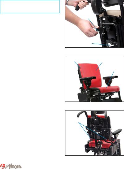
Backrest
Backrest angle and height adjust with one-hand levers.
To adjust backrest angle, squeeze white backrest angle lever and move backrest forward or backward to desired angle, then release lever (see Figure 9a).
To adjust backrest height, press backrest height lever and raise or lower backrest to desired position. Release lever and click backrest into position (see Figure 9a).
Pads
Backrest and seat pads snap into position.
Backrest pad has a Rifton tag (see Figure 9b) and is snapped onto studs (A) located behind top and bottom edge of backrest (see Figure 9c).
Seat pad has no tag and is snapped onto studs (B) located under front and back edge of seat (see Figure 9c).
Backrest angle lever
Backrest height lever
Figure 9a
Rifton tag |
Backrest pad |
Seat pad
Figure 9b
A 
B 
Figure 9c
9
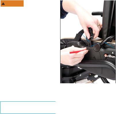
Seatbelt
WARNING To prevent falls, strangulation, head
entrapment or other injuries, always use seatbelt or pelvic harness when the tray, chest straps, thigh belt, mini trunk support, or butterfly harness are in use.
To attach seatbelt (see Figure 10a), use a |
A |
|
|
||
pen to press small white button (C) just |
|
|
below one of the slots (B) at the side of |
|
|
the seat. While keeping button depressed, |
|
|
insert the L-shaped metal clip (A) on the |
|
|
seatbelt strap into the slot with back of |
|
|
L-shape towards front of seat. Press clip |
|
|
firmly into slot and release button, making |
|
|
sure clip locks and holds when pulled. |
|
|
Repeat on other side of seat. |
|
|
To remove the seatbelt, use a pen to |
|
|
press small white button (C) just below |
Figure 10a |
|
clip slot on side of seat, and pull belt up |
||
|
||
to disengage clip. Repeat on other side |
|
|
of seat. |
|
|
Tip: Seatbelt can be clipped into either |
|
|
set of small slots at sides of chair (B). |
|
B
 C
C
10
Arm supports |
|
A pair of either armrests or forearm |
|
|
|
prompts were purchased with the |
|
chair. |
|
Insert arm supports into large slots at |
B |
|
|
either side of seat. |
|
Both types of arm supports can be removed |
|
for side transfers. |
|
To insert arm support and adjust its height, |
|
press white button (A) just below arm |
|
support slot at side of seat. Insert arm |
A |
support, move it up or down to required |
|
Figure 11a (Armrests) |
|
height, release button and make sure it |
|
audibly locks into place (see Figure 11a). |
|
To remove arm support, press white button |
|
below arm support slot at side of seat and |
|
pull arm support up. |
|
Armrests can be set at a wide range of angles.
Tip: Cut-outs on armrests should be toward back of chair.
To set angle of armrest, lift white tab (B) below outer edge of armrest (see Figure 11a) and rotate armrest to desired angle.
Release tab and make sure armrest audibly locks into place.
11
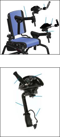
Arm supports continued. . .
Forearm prompts adjust fully to facilitate trunk and head control while sitting.
Forearm prompts are attached using a clamp and post system (see Figure 12b). The clamp attaches with a knob (F) to any position on the bar, and can be attached on the inside or outside of the bar (G) (see Figure 12a).
The post fi ts into the clamp and provides up/down and rotational adjustment.
Arm prompt can be attached to the post at several angles by sliding or rotating to achieve the best position for the user.
Loosen knob (A) to make adjustments (see Figure 12b).
Adjust the forearm prompts to the best position for a user’s comfort and function. Slide or rotate the handgrip (see Figure 12b), by loosening, then tightening knob
(C). Adjust straps (D and E) (see Figure 12a) and secure with hook and loop fasteners (hooks away from the user’s arm).
E
G
D C
 F
F
A
Figure 12a ( Forearm prompts)
C
Handgrip
A
Post
Clamp
 F
F
Figure 12b
12
 Loading...