

Page 1
OPERATOR’S MANUAL
3 in. x 18 in. BELT SANDER
VARIABLE SPEED DOUBLE INSULATED
MANUEL D’UTILISATION
PONCEUSE À BANDE DE 76 x 457 mm (3 x 18 po)
VITESSE VARIABLE DOUBLE ISOLATION
MANUAL DEL OPERADOR
LIJADORA DE BANDA DE 76 x 457 mm (3 x 18 pulg.)
VELOCIDAD VARIABLE DOBLE AISLAMIENTO
R2740
To register your RIDGID
product, please visit:
http://register.RIDGID.com
Pour enregistrer votre
produit de RIDGID,
s’il vous plaît la visite:
http://register.RIDGID.com
Para registrar su producto
de RIDGID, por favor visita:
http://register.RIDGID.com
Your belt sander has been engineered and manufactured to our high standards for dependability, ease of operation, and
operator safety. When properly cared for, it will give you years of rugged, trouble-free performance.
WARNING:
To reduce the risk of injury, the user must read and understand the operator’s manual before using this product.
Thank you for buying a RIDGID® product.
SAVE THIS MANUAL FOR FUTURE REFERENCE
Cette ponceuse à bande a été conçue et fabriquée conformément
à nos strictes normes de fiabilité, simplicité d’emploi et sécurité
d’utilisation. Correctement entretenue, elle vous donnera des
années de fonctionnement robuste et sans problème.
AVERTISSEMENT :
Pour réduire les risques de blessures, l’utilisateur doit
lire et veiller à bien comprendre le manuel d’utilisation
avant d’utiliser ce produit.
Su lijadora de banda ha sido diseñada y fabricada de conformidad
con nuestras estrictas normas para brindar fiabilidad, facilidad de
uso y seguridad para el operador. Con el debido cuidado, le brindará
muchos años de sólido y eficiente funcionamiento.
ADVERTENCIA:
Para reducir el riesgo de lesiones, el usuario debe leer
y comprender el manual del operador antes de usar
este producto.
Merci d’avoir acheté un produit RIDGID
®.
CONSERVER CE MANUEL POUR
FUTURE RÉFÉRENCE
Le agradecemos la compra de un producto RIDGID
GUARDE ESTE MANUAL PARA
FUTURAS CONSULTAS
®.
Page 2

TABLE OF CONTENTS
TABLE DES MATIÈRES / ÍNDICE DE CONTENIDO
Introduction ......................................................................................................................................................................2
Introduction / Introducción
General Power Tool Safety Warnings ............................................................................................................................3-4
Règles de sécurité relatives aux outils électriques / Advertencias de seguridad para herramientas eléctrical
Belt Sander Saw Safety Rules .......................................................................................................................................... 4
Avertissements de sécurité relatifs du ponceuse à bande / Advertencias de seguridad lijadora de bandar
Symbols ............................................................................................................................................................................ 5
Symboles / Símbolos
Electrical ........................................................................................................................................................................... 6
Caractéristiques électriques / Aspectos eléctricos
Features ............................................................................................................................................................................7
Caractéristiques / Características
Assembly .......................................................................................................................................................................... 7
Assemblage / Armado
Operation .....................................................................................................................................................................8-10
Utilisation / Funcionamiento
Adjustments .................................................................................................................................................................... 11
Réglages / Ajustes
Maintenance ..............................................................................................................................................................11-12
Entretien / Mantenimiento
Warranty .........................................................................................................................................................................13
Garantie / Garantía
Figure numbers (illustrations) ....................................................................................................................................14-15
Figure numéros (illustrations) / Figura numeras (ilustraciones)
Parts Ordering and Service ...............................................................................................................................Back Page
Commande de pièces et réparation / Pedidos de piezas y servicio ......................................................... Page arrière / Pág. posterior
INTRODUCTION
INTRODUCTION / INTRODUCCIÓN
This product has many features for making its use more pleasant and enjoyable. Safety, performance, and dependability
have been given top priority in the design of this product making it easy to maintain and operate.
* * *
Ce produit offre de nombreuses fonctions destinées à rendre son utilisation plus plaisante et satisfaisante. Lors de la
conception de ce produit, l’accent a été mis sur la sécurité, les performances et la fiabilité, afin d’en faire un outil facile à
utiliser et à entretenir.
* * *
Este producto ofrece numerosas características para hacer más agradable y placentero su uso. En el diseño de este producto
se ha conferido prioridad a la seguridad, el desempeño y la fiabilidad, por lo cual se facilita su manejo y mantenimiento.
2
Page 3

GENERAL POWER TOOL SAFETY WARNINGS
Prevent unintentional starting. Ensure the switch is in
WARNING
Read all safety warnings and all instructions.
Failure to follow the warnings and instructions may
result in electric shock, fire and/or serious injury.
Save all warnings and instructions for future reference.
The term “power tool” in the warnings refers to your mainsoperated (corded) power tool or battery-operated (cordless)
power tool.
WORK AREA SAFETY
Keep work area clean and well lit. Cluttered or dark
areas invite accidents.
Do not operate power tools in explosive atmospheres,
such as in the presence of flammable liquids, gases
or dust. Power tools create sparks which may ignite the
dust or fumes.
Keep children and bystanders away while operating a
power tool. Distractions can cause you to lose control.
ELECTRICAL SAFETY
Power tool plugs must match the outlet. Never modify
the plug in any way. Do not use any adapter plugs with
earthed (grounded) power tools. Unmodified plugs and
matching outlets will reduce risk of electric shock.
Avoid body contact with earthed or grounded surfaces
such as pipes, radiators, ranges and refrigerators.
There is an increased risk of electric shock if your body
is earthed or grounded.
Do not expose power tools to rain or wet conditions.
Water entering a power tool will increase the risk of
electric shock.
Do not abuse the cord. Never use the cord for carrying,
pulling or unplugging the power tool. Keep cord away
from heat, oil, sharp edges or moving parts. Damaged
or entangled cords increase the risk of electric shock.
When operating a power tool outdoors, use an
extension cord suitable for outdoor use. Use of a cord
suitable for outdoor use reduces the risk of electric shock.
If operating a power tool in a damp location is
unavoidable, use a ground fault circuit interrupter
(GFCI) protected supply. Use of a GFCI reduces the
risk of electric shock.
PERSONAL SAFETY
Stay alert, watch what you are doing and use common
sense when operating a power tool. Do not use a
power tool while you are tired or under the influence
of drugs, alcohol or medication. A moment of inattention
while operating power tools may result in serious personal
injury.
Use personal protective equipment. Always wear eye
protection. Protective equipment such as dust mask,
non-skid safety shoes, hard hat, or hearing protection
used for appropriate conditions will reduce personal
injuries.
3 - English
the off-position before connecting to power source
and/or battery pack, picking up or carrying the tool.
Carrying power tools with your finger on the switch or
energising power tools that have the switch on invites
accidents.
Remove any adjusting key or wrench before turning
the power tool on. A wrench or a key left attached to a
rotating part of the power tool may result in personal injury.
Do not overreach. Keep proper footing and balance at
all times. This enables better control of the power tool in
unexpected situations.
Dress properly. Do not wear loose clothing or jewellery.
Keep your hair, clothing and gloves away from moving
parts. Loose clothes, jewellery or long hair can be caught
in moving parts.
If devices are provided for the connection of dust
extraction and collection facilities, ensure these are
connected and properly used. Use of dust collection
can reduce dust-related hazards.
Do not wear loose clothing or jewelry. Contain long
hair. Loose clothes, jewelry, or long hair can be drawn
into air vents.
Do not use on a ladder or unstable support. Stable
footing on a solid surface enables better control of the
power tool in unexpected situations.
POWER TOOL USE AND CARE
Do not force the power tool. Use the correct power
tool for your application. The correct power tool will
do the job better and safer at the rate for which it was
designed.
Do not use the power tool if the switch does not turn
it on and off. Any power tool that cannot be controlled
with the switch is dangerous and must be repaired.
Disconnect the plug from the power source and/or
the battery pack from the power tool before making
any adjustments, changing accessories, or storing
power tools. Such preventive safety measures reduce
the risk of starting the power tool accidentally.
Store idle power tools out of the reach of children and
do not allow persons unfamiliar with the power tool
or these instructions to operate the power tool. Power
tools are dangerous in the hands of untrained users.
Maintain power tools. Check for misalignment or
binding of moving parts, breakage of parts and any
other condition that may affect the power tool’s
operation. If damaged, have the power tool repaired
before use. Many accidents are caused by poorly
maintained power tools.
Keep cutting tools sharp and clean. Properly maintained
cutting tools with sharp cutting edges are less likely to
bind and are easier to control.
Page 4

GENERAL POWER TOOL SAFETY WARNINGS
Use the power tool, accessories and tool bits etc.
in accordance with these instructions, taking into
account the working conditions and the work to be
performed. Use of the power tool for operations different
from those intended could result in a hazardous situation.
SERVICE
Have your power tool serviced by a qualified repair
person using only identical replacement parts. This
will ensure that the safety of the power tool is maintained.
When servicing a power tool, use only identical
replacement parts. Follow instructions in the
Maintenance section of this manual. Use of unauthorized
parts or failure to follow Maintenance instructions may
create a risk of shock or injury.
BELT SANDER SAFETY WARNINGS
Hold power tool by insulated gripping surfaces,
because the belt may contact its own cord. Cutting
a “live” wire may make exposed metal parts of the tool
“live” and could give the operator an electric shock.
Know your power tool. Read operator’s manual
carefully. Learn its applications and limitations, as
well as the specific potential hazards related to this
power tool. Following this rule will reduce the risk of
electric shock, fire, or serious injury.
Always wear safety glasses. Everyday eyeglasses
have only impact-resistant lenses; they are NOT safety
glasses. Following this rule will reduce the risk of serious
personal injury.
Protect your lungs. Wear a face or dust mask if the
operation is dusty. Following this rule will reduce the
risk of serious personal injury.
Protect your hearing. Wear hearing protection during
extended periods of operation. Following this rule will
reduce the risk of serious personal injury.
Inspect power tool cords periodically and, if damaged,
have repaired at your nearest Authorized Service
Center. Constantly stay aware of cord location.
Following this rule will reduce the risk of electric shock
or fire.
Check damaged parts. Before further use of the power
tool, a guard or other part that is damaged should be
carefully checked to determine that it will operate
properly and perform its intended function. Check for
alignment of moving parts, binding of moving parts,
breakage of parts, mounting, and any other conditions
that may affect its operation. A guard or other part that
is damaged should be properly repaired or replaced
by an Authorized Service Center. Following this rule
will reduce the risk of shock, fire, or serious injury.
Make sure your extension cord is in good condition.
When using an extension cord, be sure to use one
heavy enough to carry the current your product
will draw. A wire gauge size (A.W.G.) of at least
14 is recommended for an extension cord 50 feet
or less in length. A cord exceeding 100 feet is not
recommended. If in doubt, use the next heavier gauge.
The smaller the gauge number, the heavier the cord.
An undersized cord will cause a drop in line voltage
resulting in loss of power and overheating.
Inspect for and remove all nails from lumber before
using this power tool. Following this rule will reduce the
risk of serious personal injury.
If the power supply cord is damaged, it must be
replaced only by the manufacturer or by an authorized
service center to avoid risk.
Save these instructions. Refer to them frequently and
use them to instruct others who may use this power tool.
If you loan someone this power tool, loan them these
instructions also.
CALIFORNIA PROPOSITION 65
WARNING:
This product and some dust created by power sanding, sawing, grinding, drilling, and other construction activities may
contain chemicals, including lead, known to the State of California to cause cancer, birth defects, or other reproductive
harm. Wash hands after handling.
Some examples of these chemicals are:
• leadfromlead-basedpaints,
• crystallinesilicafrombricksandcementandothermasonryproductsand,
• arsenicandchromiumfromchemicallytreatedlumber.
Your risk from exposure to these chemicals varies, depending on how often you do this type of work. To reduce
your exposure, work in a well-ventilated area and with approved safety equipment, such as dust masks that are
specially designed to filter out microscopic particles.
4 - English
Page 5
SYMBOLS
The following signal words and meanings are intended to explain the levels of risk associated with this product.
SYMBOL SIGNAL MEANING
DANGER:
WARNING:
CAUTION:
NOTICE:
Some of the following symbols may be used on this product. Please study them and learn their meaning. Proper
interpretation of these symbols will allow you to operate the product better and safer.
Indicates an imminently hazardous situation, which, if not avoided, will result
in death or serious injury.
Indicates a potentially hazardous situation, which, if not avoided, could result
in death or serious injury.
Indicates a potentially hazardous situation, which, if not avoided, may result in
minor or moderate injury.
(Without Safety Alert Symbol) Indicates important information not related to an
injury hazard, such as a situation that may result in property damage.
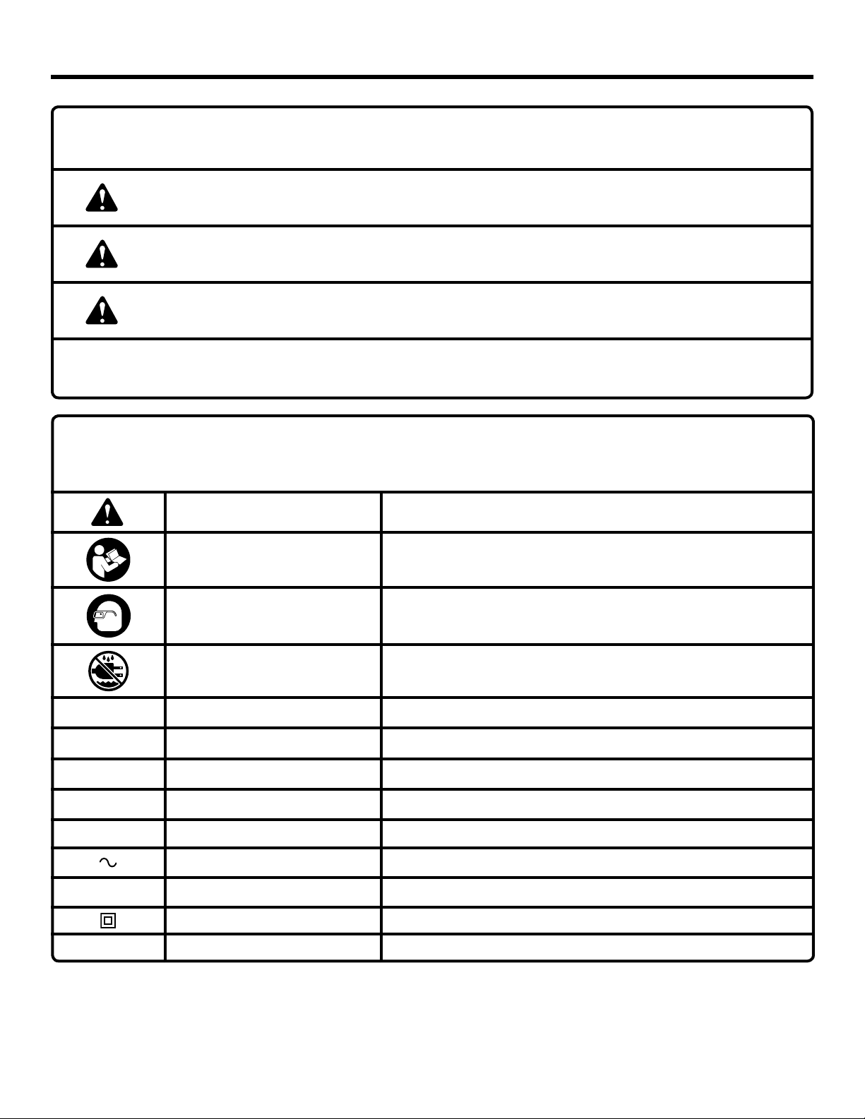
SYMBOL NAME DESIGNATION/EXPLANATION
Safety Alert Indicates a potential personal injury hazard.
Read Operator’s Manual
To reduce the risk of injury, user must read and understand
operator’s manual before using this product.
Eye Protection
Wet Conditions Alert Do not expose to rain or use in damp locations.
V Volts Voltage
A Amperes Current
Hz Hertz Frequency (cycles per second)
W Watt Power
min Minutes Time
Alternating Current Type of current
n
o
.../min Per Minute Revolutions, strokes, surface speed, orbits etc., per minute
No Load Speed Rotational speed, at no load
Class II Tool Double-insulated construction
Always wear eye protection with side shields marked to comply
with ANSI Z87.1.
5 - English
Page 6
ELECTRICAL
DOUBLE INSULATION
Double insulation is a concept in safety in electric power
tools, which eliminates the need for the usual three-wire
grounded power cord. All exposed metal parts are isolated
from the internal metal motor components with protecting
insulation. Double insulated tools do not need to be
grounded.
WARNING:
The double insulated system is intended to protect
the user from shock resulting from a break in the
tool’s internal wiring. Observe all normal safety
precautions to avoid electrical shock.
NOTE: Servicing of a tool with double insulation requires
extreme care and knowledge of the system and should
be performed only by a qualified service technician. For
service, we suggest you return the tool to your nearest
authorized service center for repair. Always use original
factory replacement parts when servicing.
ELECTRICAL CONNECTION
This product has a precision-built electric motor. It should
be connected to a power supply that is 120 volts, 60 Hz,
AC only (normal household current). Do not operate this
tool on direct current (DC). A substantial voltage drop will
cause a loss of power and the motor will overheat. If your
tool does not operate when plugged into an outlet, doublecheck the power supply.
EXTENSION CORDS
When using a power tool at a considerable distance from
a power source, be sure to use an extension cord that has
the capacity to handle the current the tool will draw. An
undersized cord will cause a drop in line voltage, resulting in
overheating and loss of power. Use the chart to determine
the minimum wire size required in an extension cord. Only
round jacketed cords listed by Underwriter’s Laboratories
(UL) should be used.
When working outdoors with a tool, use an extension
cord that is designed for outside use. This type of cord is
designated with “WA” or “W” on the cord’s jacket.
Before using any extension cord, inspect it for loose or
exposed wires and cut or worn insulation.
**Ampere rating (on tool data plate)
0-2.0 2.1-3.4 3.5-5.0 5.1-7.0 7.1-12.0 12.1-16.0
Cord Length Wire Size (A.W.G.)
25' 16 16 16 16 14 14
50' 16 16 16 14 14 12
100' 16 16 14 12 10 —
**Used on 12 gauge - 20 amp circuit.
NOTE: AWG = American Wire Gauge
WARNING:
Keep the extension cord clear of the working area.
Position the cord so that it will not get caught on
lumber, tools or other obstructions while you are
working with a power tool. Failure to do so can
result in serious personal injury.
6 - English
WARNING:
Check extension cords before each use. If
damaged replace immediately. Never use tool with
a damaged cord since touching the damaged area
could cause electrical shock resulting in serious
injury.
Page 7
FEATURES
PRODUCT SPECIFICATIONS
Belt Size ..........................................................3 in. x 18 in.
Sanding Surface ............................................... 17.5 sq. in.
No Load Speed ...................................... 400 - 950 ft./min.
Input ...............................120 V, 60 Hz, AC only, 6.5 Amps
Net Weight .............................................................. 5.8 lbs.
KNOW YOUR BELT SANDER
See Figure 1, page 14.
The safe use of this product requires an understanding of
the information on the tool and in this operator’s manual as
well as a knowledge of the project you are attempting. Before
use of this product, familiarize yourself with all operating
features and safety rules.
BELT TENSION RELEASE LEVER
The tension release lever aids in quick and easy belt
changes.
DUST BAG
The dust bag attaches to the sander and keeps dust to a
minimum.
ERGONOMIC DESIGN
The design provides for easy handling. It is designed for
comfort and ease of operation in different positions and at
different angles.
ASSEMBLY
UNPACKING
This product has been shipped completely assembled.
Carefully remove the product and any accessories from
the box. Make sure that all items listed in the packing list
are included.
LOCK-ON BUTTON
The lock-on feature allows you to lock the switch trigger in
the ON position. Locking the switch trigger on allows you to
operate the sander for extended periods of time.
SWITCH TRIGGER
To turn the sander ON, depress the switch trigger. Release
switch trigger to turn your sander OFF.
TRACKING SCREW
The tracking screw allows you to easily adjust the belt
tracking.
VARIABLE SPEED CONTROL DIAL
The variable speed control feature allows the sander to
develop a no load speed that can be adjusted from 400
to 950 feet/min. by rotating the dial from A (slowest) to F
(fastest).
WARNING:
If any parts are damaged or missing do not operate
this product until the parts are replaced. Use of
this product with damaged or missing parts could
result in serious personal injury.
WARNING:
Do not use this product if it is not completely
assembled or if any parts appear to be missing
or damaged. Use of a product that is not properly
and completely assembled could result in serious
personal injury.
Inspect the product carefully to make sure no breakage
or damage occurred during shipping.
Do not discard the packing material until you have carefully
inspected and satisfactorily operated the product.
If any parts are damaged or missing, please call
1-866-539-1710 for assistance.
PACKING LIST
Variable Speed Belt Sander
Dust Collection Bag
Sanding Belt
Operator’s Manual
7 - English
WARNING:
Do not attempt to modify this product or create
accessories not recommended for use with this
product. Any such alteration or modification is
misuse and could result in a hazardous condition
leading to possible serious personal injury.
WARNING:
Do not connect to power supply until assembly
is complete. Failure to comply could result in
accidental starting and possible serious personal
injury.
Page 8

OPERATION
WARNING:
Do not allow familiarity with products to make you
careless. Remember that a careless fraction of a
second is sufficient to inflict serious injury.
APPLICATIONS
You may use this product for the purposes listed below:
Sanding wood, metals, and plastics
Smoothing rough boards, chamfering, rounding edges
Removing rust, paint, varnishes, and stains
WARNING:
Always wear eye protection marked to comply with
ANSI Z87.1. Failure to do so could result in objects
being thrown into your eyes resulting in possible
serious injury.
WARNING:
Do not use any attachments or accessories
not recommended by the manufacturer of this
product. The use of attachments or accessories
not recommended can result in serious personal
injury.
WARNING:
Before connecting the sander to a power supply,
make sure it is not in the locked-on position. Failure
to do so could result in accidental starting of the
tool resulting in serious injury.
MATERIAL
UNDRESSED
LUMBER
A B C D E F 40 60 80 100 150 240
SPEED BELT GRIT
WARNING:
If your sanding job becomes dusty or if you have a
breathing condition, wear a dust mask or respirator
to prevent damage to your health.
SELECTING SANDING BELTS
Selecting the correct size and type of sanding belt is an
important step in achieving a high quality sanded finish. Aluminum oxide, silicon carbide, and other synthetic abrasives
are best for power sanding.
In general, when sanding, coarse grit removes the most material and fine grit produces the best finish. The condition of
the surface to be sanded determines which grit will do the
best job. If the surface is rough, start with a coarse grit and
sand until the surface is uniform. Then use medium grit to
remove scratches left by the coarser grit. Finally, use finer
grit for finishing the surface. Always continue sanding with
each grit until the surface is uniform.
SETTING THE BELT SANDER SPEED
Refer to the chart below for belt sander speed selections.
SOFTWOOD
CHIPBOARD
LUMBER
RUST REMOVAL
PAINTED SURFACE
NON-FERROUS
METAL
8 - English
Page 9
OPERATION
VARIABLE SPEED CONTROL DIAL
See Figure 2, page 14.
The sander has a variable speed control dial, A (slowest)
to F (fastest), designed to allow operator control of belt
speed. To increase belt speed, turn the variable speed
control dial to a higher setting. Turn to a lower setting to
decrease belt speed. Refer to the chart on page 9 for proper
speed selections.
PROPER HAND PLACEMENT
See Figure 3, page 14.
The front and rear handles allow two-handed operation
which aids in maintaining control, keeping sander level
with workpiece, and keeping hands clear of sanding belt.
When carrying or operating the sander always hold the front
handle with the left hand and the rear handle with the right
hand as shown.
WARNING:
Keep hands and fingers clear of moving sanding
belt, front pulley, and drive roller assembly. Failure
to do so will result in the sanding of the hands or
fingers possibly causing serious injury.
WARNING:
Keep hands and fingers clear of front roller and
spring mechanism at all times. Failure to do so
could result in fingers getting pinched, causing
possible serious injury.
Belt tension must be released in order to install and remove
sanding belt:
Release belt tension by lifting tension release lever.
Install sanding belt; make sure arrow inside of belt is
pointing in the direction of rotation, which is clockwise
when looking into open side of sander.
NOTE: Match the arrow on the sanding belt to that of the
housing.
CAUTION:
If the sanding belt is not a bidirectional belt,
ensure that the arrow inside the belt is pointing
in the direction of the rotation (clockwise when
looking into the open side of the sander). Installing
unidirectional sanding belts backwards can create
a hazardous condition.
WARNING:
Do not let your fingers rest over the front or right
edge of the sander. If the sanding belt were to run
off, or if it were not properly adjusted, your fingers
could come in contact with the moving sanding
belt resulting in possible serious injury.
TURNING ON/OFF THE SANDER
See Figure 4, page 14.
To turn on the sander: Depress the switch trigger.
To turn off the sander: Release the switch trigger.
SOFT START FEATURE
Soft start is a feature whereby the motor gradually ramps
up to the selected top speed. For example, when a speed
is selected with the speed limiting dial and the sander is
stopped and then activated again, the sander will gradually
ramp up to the previous speed setting once the switch trigger
is pressed again.
TO INSTALL/CHANGE SANDING BELT
See Figures 5 - 6, page 14.
Unplug the sander.
Position sander as shown.
Align the sanding belt to its correct position.
Lower tension release lever to secure the sanding belt.
NOTE: This sander is equipped with automatic tracking,
which in most instances will cause the sanding belt to remain
centered. If the sanding belt does not stay in the center area,
manual adjustment of the belt tracking may be necessary.
To manually adjust, see Manually Adjusting Sanding Belt
Tracking in the Adjustments section of this manual.
LOCKING ON THE SANDER
See Figure 7, page 15.
The lock-on feature allows you to lock the switch trigger in
the ON position. Locking the switch trigger on allows you to
operate the sander for extended periods of time.
If you have the lock-on feature engaged during use and the
sander is accidentally disconnected from the power supply,
disengage the lock-on feature immediately. Also, do not
lock the switch trigger if you might need to suddenly stop
the sander.
To lock-on the sander:
Depress the switch trigger.
Push in the lock-on button.
Release the switch trigger.
Release the lock-on button.
NOTE: To release the lock, depress and release the switch
trigger.
9 - English
Page 10
OPERATION
OPERATING THE SANDER
See Figure 8, page 15.
Clamp or otherwise secure the work to prevent it from
moving under the sander.
WARNING:
Unsecured work could be thrown back toward
operator causing injury.
Before placing sander on work surface, squeeze the switch
trigger and let the motor reach its maximum speed, then
lower the sander to the work surface with a slight forward
motion. Using the rear handle to control the sander and the
front handle only to guide it, move it slowly over the work.
Allowing the sander to remain in one place will result in an
uneven surface.
WARNING:
Keep a firm grip on sander with both hands at all
times. Failure to do so could result in loss of control
leading to possible serious injury.
The sander was designed to provide the proper weight on
the sanding belt.
Excessive pressure will result in the following:
Uneven work.
Clogged sanding belts.
Premature sanding belt wear. Removal rate will not
increase.
Motor damage.
Irregular sanding belt tracking.
NOTE: If the sanding belt moves while sanding, you may
be applying too much pressure. When this occurs, remove
sander from workpiece. If belt tracking is properly adjusted,
sanding belt will return to its normal and correct position on
the drive roller and front roller.
Use a coarser belt when heavy sanding is desired, not
heavy pressure. The importance of this cannot be overemphasized. Weight has been built into the tool to give the
most efficient pressure at the proper location.
NOTE: The front roller of the sander was not designed for
contour sanding. Sanding on the front roller could cause
irregularity in sanding belt tracking and will damage the
front roller.
CAUTION:
Sanding on the front roller may cause the tool to
kickback toward the operator, creating a risk of
possible injury.
WARNING:
The sander is designed to be operated as shown
in Figure 8, page 15 with both hands on the tool at
all times for maximum control. Never operate the
tool overhead or inverted from the proper operating
position; serious personal injury may result.
WARNING:
Do not use the dust collection bag when sanding
metal. Using the dust collection bag when sanding
metal creates a fire hazard, which could damage
the tool and lead to serious personal injury.
DUST BAG
See Figure 9, page 15.
The dust bag provides a dust collection system for the
sander. It should be installed over the exhaust hole located
on the side of the sander. For more efficient operation, empty
dust bag when half full.
Do not connect sander to power supply before installing
dust bag.
To install/remove dust bag:
Unplug the sander.
Place the opening of dust bag over dust exhaust of the
sander.
EMPTYING THE DUST BAG
See Figure 10, page 15.
For more efficient operation, empty dust bag when no more
than half full. This will permit the air to flow through the bag
better. Always empty and clean the dust bag thoroughly
upon completion of a sanding operation and before placing
the sander in storage.
WARNING:
Collected sanding dust from sanding surface
coatings such as polyurethanes, linseed oil, etc.,
can self-ignite in the sander dust bag or elsewhere
and cause fire. To reduce the risk of fire, always
empty the dust bag frequently while sanding. Never
store or leave a sander without totally emptying its
dust bag. Also follow the recommendations of the
coatings manufacturers.
To empty the dust bag:
Unplug the sander.
Remove dust bag from sander.
Open zipper.
Shake out dust.
Replace dust bag on sander.
10 - English
Page 11
ADJUSTMENTS
MANUALLY ADJUSTING SANDING BELT
TRACKING
See Figure 11, page 15.
This sander features an automatic tracking system designed
to keep the sanding belt centered. If edge sanding is desired,
manual adjustment of the belt will be necessary.
To manually adjust belt position:
Connect the sander to power supply.
Set the variable speed control dial to the lowest setting
(A).
With sander positioned as shown, pull switch trigger.
NOTE: This position is for adjustments only. Sanding belt
should not be in contact with workpiece or any foreign
objects when making belt tracking adjustments.
MAINTENANCE
WARNING:
When servicing use only identical replacement
parts. Use of any other parts may create a hazard
or cause product damage.
WARNING:
Always wear eye protection marked to comply with
ANSI Z87.1. Failure to do so could result in objects
being thrown into your eyes resulting in possible
serious injury.
GENERAL MAINTENANCE
Avoid using solvents when cleaning plastic parts. Most
plastics are susceptible to damage from various types of
commercial solvents and may be damaged by their use. Use
clean cloths to remove dirt, dust, oil, grease, etc.
WARNING:
Do not at any time let brake fluids, gasoline,
petroleum-based products, penetrating oils, etc.,
come in contact with plastic parts. Chemicals can
damage, weaken or destroy plastic which may
result in serious personal injury.
Slowly turn the tracking screw clockwise until the sanding
belt is positioned at the edge of the platen. Do not allow
the sanding belt to extend past the edge of the platen.
WARNING:
Keep hands and fingers away from moving
sanding belt. Any part of body coming in contact
with moving sanding belt could result in serious
injury. Do not wear loose clothing or jewelry when
operating sander. They could get caught in moving
parts and foreign objects could get thrown from
sander causing injury.
When edge sanding is completed, return the belt to the
default centered position by turn the tracking screw
counterclockwise until the belt is positioned correctly.
Electric tools used on fiberglass material, wallboard,
spackling compounds, or plaster are subject to accelerated
wear and possible premature failure because the fiberglass
chips and grindings are highly abrasive to bearings, brushes,
commutators, etc. Consequently, we do not recommended
using this tool for extended work on these types of materials.
However, if you do work with any of these materials, it is
extremely important to clean the tool using compressed
air.
LUBRICATION
All of the bearings in this tool are lubricated with a sufficient
amount of high grade lubricant for the life of the unit under
normal operating conditions. Therefore, no further lubrication
is required.
BRUSH REPLACEMENT
See Figure 12, page 15.
NOTE: This belt sander is equipped with externally
accessible brushes.
Unplug the sander.
WARNING:
Failure to unplug the tool could result in accidental
starting causing possible serious injury.
Remove brush caps (2) using a screwdriver.
Remove brush assemblies (2).
11 - English
Page 12

MAINTENANCE
Check for wear. Replace both brush assemblies when
either has less than 1/4 in. length of carbon remaining.
NOTE: Do not replace one side without replacing the
other.
Reassemble using new brush assemblies. Make sure
curvature of brush matches curvature of motor and that
brush moves freely in brush tube.
Reassemble by reversing the steps listed above.
Tighten all brush caps securely. Do not over tighten.
TIMING BELT REPLACEMENT
See Figure 13, page 15.
Unplug the sander.
Remove dust bag.
Remove sanding belt from sander. Follow instructions on
page 9 to remove sanding belt.
NOTE: Removing sanding belt will simplify the process
of installing a new timing belt.
Remove belt cover screw and belt cover.
Force old timing belt from one of the small pulleys with
a screwdriver and remove it while turning the large
pulley. If it is worn out, simply cut the old timing belt and
remove.
Install new timing belt over large pulley and one of the
small pulleys first.
Press the belt onto the other small pulley, turning the
large pulley as you press the belt on.
Reinstall belt cover and screw.
Tighten screw securely.
Reinstall the sanding belt.
WARNING:
Never attempt to operate the belt sander without
the belt cover in place.
NOTE: FIGURES (ILLUSTRATIONS) START ON PAGE 14
AFTER FRENCH AND SPANISH LANGUAGE SECTIONS
12 - English
Page 13

WARRANTY
RIDGID® HAND HELD AND STATIONARY POWER TOOL
3 YEAR LIMITED SERVICE WARRANTY
Proof of purchase must be presented when requesting
warranty service.
Limited to RIDGID
purchased 2/1/04 and after. This product is manufactured
by One World Technologies, Inc. The trademark is licensed
from RIDGID, Inc. All warranty communications should be
directed to One World Technologies, Inc., attn: RIDGID Hand
Held and Stationary Power Tool Technical Service at (toll
free) 1-866-539-1710.
® hand held and stationary power tools
90-DAY SATISFACTION GUARANTEE POLICY
During the first 90 days after the date of purchase, if you are
dissatisfied with the performance of this RIDGID® Hand Held
and Stationary Power Tool for any reason you may return
the tool to the dealer from which it was purchased for a full
refund or exchange. To receive a replacement tool you must
present proof of purchase and return all original equipment
packaged with the original product. The replacement tool
will be covered by the limited warranty for the balance of
the 3 YEAR service warranty period.
WHAT IS COVERED UNDER THE 3 YEAR
LIMITED SERVICE WARRANTY
This warranty on RIDGID® Hand Held and Stationary Power
Tools covers all defects in workmanship or materials and
normal wear items such as brushes, chucks, motors,
switches, cords, gears and even cordless batteries in this
RIDGID® tool for three years following the purchase date of
the tool. Warranties for other RIDGID® products may vary.
HOW TO OBTAIN SERVICE
To obtain service for this RIDGID® tool you must return it;
freight prepaid, or take it in to an authorized service center
for RIDGID® branded hand held and stationary power
tools. You may obtain the location of the authorized service
center nearest you by calling (toll free) 1-866-539-1710 or
by logging on to the RIDGID® website at www.ridgid.com.
When requesting warranty service, you must present the
original dated sales receipt. The authorized service center will
repair any faulty workmanship, and either repair or replace
any part covered under the warranty, at our option, at no
charge to you.
WHAT IS NOT COVERED
This warranty applies only to the original purchaser at retail
and may not be transferred. This warranty only covers
defects arising under normal usage and does not cover
any malfunction, failure or defect resulting from misuse,
abuse, neglect, alteration, modification or repair by other
than an authorized service center for RIDGID® branded hand
held and stationary power tools. Consumable accessories
provided with the tool such as, but not limited to, blades,
bits and sand paper are not covered.
RIDGID, INC. AND ONE WORLD TECHNOLOGIES, INC.
MAKE NO WARRANTIES, REPRESENTATIONS OR
PROMISES AS TO THE QUALITY OR PERFORMANCE OF
ITS POWER TOOLS OTHER THAN THOSE SPECIFICALLY
STATED IN THIS WARRANTY.
ADDITIONAL LIMITATIONS
To the extent permitted by applicable law, all implied
warranties, including warranties of MERCHANTABILITY or
FITNESS FOR A PARTICULAR PURPOSE, are disclaimed. Any
implied warranties, including warranties of merchantability or
fitness for a particular purpose, that cannot be disclaimed
under state law are limited to three years from the date
of purchase. One World Technologies, Inc. and RIDGID,
Inc. are not responsible for direct, indirect, incidental or
consequential damages. Some states do not allow limitations
on how long an implied warranty lasts and/or do not allow
the exclusion or limitation of incidental or consequential
damages, so the above limitations may not apply to you.
This warranty gives you specific legal rights, and you may
also have other rights which vary from state to state.
One World Technologies, Inc.
P.O. Box 35, Hwy. 8
Pickens, SC 29671
13 - English
Page 14

RÈGLES DE SÉCURITÉ RELATIVES AUX OUTILS ÉLECTRIQUES
Un moment d’inattention pendant l’utilisation d’un outil
AVERTISSEMENT
Lire tous les avertissements et toutes les
instructions. Ne pas suivre l’ensemble des
avertissements et des instructions peut entraîner
une électrocution, un incendie ou des blessures
graves
.
Conserver les avertissements et les instructions à des fins
de référence ultérieure. Le terme « outil motorisé », utilisé
dans tous les avertissements ci-dessous désigne tout outil
fonctionnant sur secteur (câblé) ou sur piles (sans fil).
SÉCURITÉ DU LIEU DE TRAVAIL
Garder le lieu de travail propre et bien éclairé. Les
endroits encombrés ou sombre s sont propices aux
accidents.
Ne pas utiliser d’outils électriques dans des atmosphères
explosives, par exemple en présence de liquides, gaz
ou poussières inflammables. Les outils électriques
produisent des étincelles risquant d’enflammer les
poussières ou vapeurs.
Garder les enfants et badauds à l’écart pendant
l’utilisation d’un outil électrique. Les distractions peuvent
causer une perte de contrôle.
SÉCURITÉ ÉLECTRIQUE
Les fiches des outils électriques doivent correspondre
à la prise secteur utilisée. Ne jamais modifier la fiche,
de quelque façon que ce soit. Ne jamais utiliser
d’adaptateurs de fiche avec des outils mis à la terre.
Les fiches et prises non modifiées réduisent le risque de
choc électrique.
Éviter tout contact du corps avec des surfaces mises
à la terre, telles que tuyaux, radiateurs, cuisinières et
réfrigérateurs. Le risque de choc électrique est accru
lorsque le corps est mis à la terre.
Ne pas exposer les outils électriques à l’eau ou
l’humidité. La pénétration d’eau dans ces outils accroît
le risque de choc électrique.
Ne pas maltraiter le cordon d’alimentation. Ne jamais
utiliser le cordon d’alimentation pour transporter
l’outil et ne jamais débrancher ce dernier en tirant sur
le cordon. Garder le cordon à l’écart de la chaleur,
de l’huile, des objets tranchants et des pièces en
mouvement. Un cordon endommagé ou emmêlé accroît
le risque de choc électrique.
Pour les travaux à l’extérieur, utiliser un cordon
spécialement conçu à cet effet. Utiliser un cordon conçu pour
l’usage extrérieur pour réduire les risques de choc électrique.
S’il est nécessaire d’utiliser l’outil électrique dans un
endroit humide, employer un dispositif interrupteur de
défaut à la terre (GFCI). L’utilisation d’un GFCI réduit le
risque de décharge électrique.
SÉCURITÉ PERSONNELLE
Rester attentif, prêter attention au travail et faire preuve
de bon sens lors de l’utilisation de tout outil électrique.
Ne pas utiliser cet outil en état de fatigue ou sous
l’influence de l’alcool, de drogues ou de médicaments.
électrique peut entraîner des blessures graves.
Utiliser l’équipement de sécurité. Toujours porter une
protection oculaire. L’équipement de sécurité, tel qu’un
masque filtrant, de chaussures de sécurité, d’un casque
ou d’une protection auditive, utilisé dans des conditions
appropriées réduira le risque de blessures.
Éviter les démarrages accidentels. S’assurer que le
commutateur est en position d’arrêt avant de brancher
l’outil. Porter un outil avec le doigt sur son commutateur
ou brancher un outil dont le commutateur est en position
de marche peut causer un accident.
Retirer les clés de réglage avant de mettre l’outil en
marche. Une clé laissée sur une pièce rotative de l’outil
peut causer des blessures.
Ne pas travailler hors de portée. Toujours se tenir bien
campé et en équilibre. Ceci permettra de mieux contrôler
l’outil en cas de situation imprévue.
Porter une tenue appropriée. Ne porter ni vêtements
amples, ni bijoux. Garder les cheveux, les vêtements
et les gants à l’écart des pièces en mouvement. Les
vêtements amples, bijoux et cheveux longs peuvent se
prendre dans les pièces en mouvement.
Si les outils sont équipés de dispositifs de dépoussiérage,
s’assurer qu’ils sont connectés et correctement
utilisés. L’usage de ces dispositifs de dépoussiérage peut
réduire les dangers présentés par la poussière.
Ne porter ni vêtements amples, ni bijoux. Attacher
ou couvrir les cheveux longs. Les vêtements amples,
bijoux et cheveux longs peuvent se prendre dans les ouïes
d’aération.
Ne pas utiliser l’outil sur une échelle ou un support
instable. Une bonne tenue et un bon équilibre permettent
de mieux contrôler l’outil en cas de situation imprévue.
UTILISATION ET ENTRETIEN DES OUTILS
ÉLECTRIQUES
Ne pas forcer l’outil. Utiliser l’outil approprié pour
l’application. Un outil approprié exécutera le travail mieux et de
façon moins dangereuse s’il est utilisé dans les limites prévues.
Ne pas utiliser l’outil si le commutateur ne permet pas
de le mettre en marche ou de l’arrêter. Tout outil qui ne
peut pas être contrôlé par son commutateur est dangereux
et doit être réparé.
Débrancher l’outil et/ou retirer le bloc-piles avant
d’effectuer des réglages, de changer d’accessoire ou
de remiser l’outil. Ces mesures de sécurité préventives
réduisent les risques de démarrage accidentel de l’outil.
Ranger les outils motorisés hors de la portée des
enfants et ne laisser personne n’étant pas familiarisé
avec l’outil ou ces instructions utiliser l’outil. Dans les
mains de personnes n’ayant pas reçu des instructions
adéquates, les outils sont dangereux.
Entretenir les outils motorisés. Vérifier qu’aucune pièce
mobile n’est mal alignée ou bloquée, qu’aucune pièce
n’est brisée et s’assurer qu’aucun autre problème ne
risque d’affecter le bon fonctionnement de l’outil. En
cas de dommages faire réparer l’outil avant de l’utiliser
de nouveau. Beaucoup d’accidents sont causés par des
outils mal entretenus.
3 - Français
Page 15

RÈGLES DE SÉCURITÉ RELATIVES AUX OUTILS ÉLECTRIQUES
Garder les outils bien affûtés et propres. Des outils
correctement entretenus et dont les tranchants sont bien affûtés
risquent moins de se bloquer et sont plus faciles à contrôler.
Utiliser l’outil, les accessoires et embouts, etc. conformément
à ces instrutions pour les applications pour lesquelles ils
sont conçus, en tenant compte des conditions et du type
de travail à exécuter. L’usage d’un outil motorisé pour des
applications pour lesquelles il n’est pas conçu peut être
dangereux.
DÉPANNAGE
Les réparat ions doivent être confiées à un technicien
qualifié, utilisant exclusivement des pièces identiques à
celles d’origine. Ceci assurera le maintien de la sécurité de l’outil.
Utiliser exclusivement des pièces identiques à celles
d’origine pour les réparations. Se conformer aux instructions
de la section Entretien de ce manuel. L’usage de pièces non
autorisées ou le non-respect des instructions peut présenter
AVERTISSEMENTS DE SÉCURITÉ RELATIFS AU PONCEUSE À BANDE
Tenir l’outil électrique par ses surfaces de préhension
isolées étant donné que la courroie peut entrer en contact
avec le cordon d’alimentation de l’outil. Le fait de couper un
fil sous tension « électrifie » les pièces métalliques exposées
de l’outil et peut électrocuter l’utilisateur.
Apprendre à connaître l’outil. Lire attentivement le manuel
d’utilisation. Apprendre les applications et les limites
de l’outil, ainsi que les risques spécifiques relatifs à son
utilisation. Le respect de cette consigne réduira les risques
d’incendie, de choc électrique et de blessures graves.
Toujours porter des lunettes de sécurité. Les lunettes
ordinaires sont dotées de verres résistants aux impacts
seulement ; ce ne sont PAS des lunettes de sécurité. Le
respect de cette consigne réduira les risques de blessures
graves.
Protection respiratoire. Porter un masque facial ou un
masque anti-poussière si le travail produit de la poussière.
Le respect de cette consigne réduira les risques de blessures
graves.
Protection auditive. Porter une protection auditive durant les
périodes d’utilisation prolongée. Le respect de cette consigne
réduira les risques de blessures graves.
Inspecter régulièrement les cordon d’alimentation des outils
motorisés. S’ils sont endommagés, les confier au centre de
réparations agréé le plus proche. Toujours être conscient
de l’emplacement du cordon. Le respect de cette consigne
réduira les risques de choc électrique et d’incendie.
Vérifier l’état des pièces. Avant d’utiliser l’outil de nouveau
examiner soigneusement les pièces et dispositifs de
protection qui semblent endommagés afin de déterminer
s’ils fonctionnent correctement et s’ils remplissent les
fonctions prévues. Vérifier l’alignement des pièces mobiles,
s’assurer qu’aucune pièce n’est bloquée ou cassée, vérifier
la fixation de chaque pièce et s’assurer qu’aucun autre
problème ne risque d’affecter le bon fonctionnement de
l’outil. Toute protection ou pièce endommagée doit être
correctement réparée ou remplacée dans un centre de
réparations agréé. Le respect de cette consigne réduira les
risques de choc électrique, d’incendie et de blessures graves.
S’assurer que le cordon prolongateur est en bon état. Si un
cordon prolongateur est utilisé, s’assurer que sa capacité
est suffisante pour supporter le courant de fonctionnement
de l’outil. Un calibre de fil (A.W.G) d’au minimum 14 est
recommandé pour un cordon prolongateur de 15 m (50
pi) maximum. Un cordon de plus de 30 m (100 pi) est
déconseillé. En cas de doute, utiliser un cordon du calibre
immédiatement supérieur. Moins le numéro de calibre
est élevé, plus la capacité du fil est grande. Un cordon de
capacité insuffisante causerait une baisse de la tension de ligne,
entraînant une perte de puissance et une surchauffe.
Inspecter la pièce et retirer les clous éventuels avant
d’utiliser cet outil. Le respect de cette consigne réduira les
risques de blessures graves.
Si le cordon d’alimentation est endommagé, il doit être
remplacé uniquement pas le fabricant ou par un centre de
réparation agréé pour éviter tout risque.
Conserver ces instructions. Les consulter fréquemment et
les utiliser pour instruire les autres utilisateurs éventuels. Si cet
outil est prêté, il doit être accompagné de ces instructions.
PROPOSITION 65 DE L’ÉTAT DE CALIFORNIE
AVERTISSEMENT :
Ce produit et la poussière dégagée lors du ponçage, sciage, meulage, perçage de certains matériaux et lors d’autres opérations
de construction peuvent contenir des produits chimiques, notamment du plomb qui, selon l’État de la Californie, peuvent causer
le cancer, des anomalies congénitales et d’autres dommages au système reproducteur. Bien se laver les mains après toute
manipulation.
Voici certains exemples de ces produits chimiques :
• leplombcontenudanslapeintureauplomb,
• lasilicecristallinecontenuedanslesbriques,lebétonetd’autresproduitsdemaçonnerie,ainsique,
• l’arsenicetlechromecontenusdansleboisdeconstructiontraitéparproduitschimiques.
Le risque présenté par l’exposition à ces produits varie en fonction de la fréquence de ce type de travail. Pour réduire l’exposition,
travailler dans un endroit bien aéré et utiliser des équipements de sécurité approuvés tels que masques antipoussières
spécialement conçus pour filtrer les particules microscopiques.
4 - Français
Page 16

SYMBOLES
Les termes de mise en garde suivants et leur signification ont pour but d’expliquer le degré de risques associé à
l’utilisation de ce produit.
SYMBOLE SIGNAL SIGNIFICATION
DANGER :
AVERTISSEMENT :
ATTENTION :
AVIS :
Certains des symboles ci-dessous peuvent être utilisés sur produit. Veiller à les étudier et à apprendre leur signification. Une
interprétation correcte de ces symboles permettra d’utiliser produit plus efficacement et de réduire les risques.
Indique une situation extrêmement dangereuse qui, si elle n’est pas évitée,
aura pour conséquences des blessures graves ou mortelles.
Indique une situation potentiellement dangereuse qui, si elle n’est pas
évitée, pourrait entraîner des blessures graves ou mortelles.
Indique une situation potentiellement dangereuse qui, si elle n’est pas
évitée, pourraît entraîner des blessures légères ou de gravité modérée.
(Sans symbole d’alerte de sécurité) Indique une information importante
ne concernant pas un risque de blessure comme une situation pouvant
occasionner des dommages matériels.
SYMBOLE NOM DÉSIGNATION / EXPLICATION
Symbole d’alerte de
sécurité
Lire le manuel d’utilisation
Indique un risque de blessure potentiel.
Pour réduire les risques de blessures, l’utilisateur doit lire et veiller à
bien comprendre le manuel d’utilisation avant d’utiliser ce produit.
Protection oculaire
Avertissement concernant
l’humidité
V Volts Tension
A Ampères Intensité
Hz Hertz Fréquence (cycles par seconde)
W Watts Puissance
min Minutes Temps
Courant continu Type ou caractéristique du courant
Vitesse à vide Vitesse de rotation à vide
Outil de la classe II Construction à double isolation
.../min Par minute Tours, coups, vitesse périphérique, orbites, etc., par minute
Toujours porter une protection oculaire avec écrans latéraux
certifiée conforme à la norme ANSI Z87.1.
Ne pas exposer à la pluie ou l’humidité.
5 - Français
Page 17

CARACTÉRISTIQUES ÉLECTRIQUES
DOUBLE ISOLATION
La double isolation est un dispositif de sécurité utilisé sur les
outils à moteur électriques, éliminant le besoin de cordon
d’alimentation habituel à trois fils avec terre. Toutes les
pièces métalliques exposées sont isolées des composants
internes du moteur par l’isolation protectrice. Les outils à
double isolation ne nécessitent pas de mise à la terre.
AVERTISSEMENT :
Le système à double isolation est conçu pour
protéger l’utilisateur contre les chocs électriques
causés par une rupture du câblage interne de
l’outil. Prendre toutes les précautions de sécurité
normales pour éviter les chocs électriques.
NOTE : La réparation d’un outil à double isolation exigeant
des précautions extrêmes ainsi que la connaissance du
système, elle ne doit être confiée qu’à un réparateur qualifié.
En ce qui concerne les réparations, nous recommandons de
confier l’outil au centre de réparation le plus proche. Utiliser
exclusivement des pièces d’origine pour les réparations.
CONNEXIONS ÉLECTRIQUES
Ce produit est équipé d’un moteur électrique de précision. Il
doit être branché uniquement sur une alimentation 120 V,
60 Hz, c.a. (courant résidentiel standard). Ne pas utiliser
cet outil sur une source de courant continu ( c.c. ). Une chute
de tension importante causerait une perte de puissance et
une surchauffe du moteur. Si l’outil ne fonctionne pas une
fois branché, vérifier l’alimentation électrique.
CORDONS PROLONGATEURS
Lors de l’utilisation d’un outil électrique à grande distance
d’une prise secteur, veiller à utiliser un cordon prolongateur
d’une capacité suffisante pour supporter l’appel de courant
de l’outil. Un cordon de capacité insuffisante causerait
une baisse de la tension de ligne, entraînant une perte
de puissance et une surchauffe. Se reporter au tableau
ci-dessous pour déterminer le calibre minimum de fil requis
pour un cordon donné. Utiliser exclusivement des cordons à
gaine cylindrique homologués par Underwriter’s Laboratories
(UL).
Pour le travail à l’extérieur, utiliser un cordon prolongateur
spécialement conçu à cet effet. Ce type de cordon porte
l’inscription « WA » ou « W » sur sa gaine.
Avant d’utiliser un cordon prolongateur, vérifier que ses fils
ne sont ni détachés ni exposés et que son isolation n’est ni
coupée, ni usée.
**Intensité nominale (sur la plaquette signalétique de l’outil)
0-2,0 2,1-3,4 3,5-5,0 5,1-7,0 7,1-12,0 12,1-16,0
Longueur du Calibre de fil
cordon (A.W.G.)
25' 16 16 16 16 14 14
50' 16 16 16 14 14 12
100’ 16 16 14 12 10
**Utilisé sur circuit de calibre 12 – 20 A
NOTE : AWG = American Wire Gauge
AVERTISSEMENT :
Maintenir le cordon prolongateur à l’écart de la
zone de travail. Lors du travail avec un cordon
électrique, placer le cordon de manière à ce qu’il ne
risque pas de se prendre dans les pièces de bois,
outils et autres obstacles. Ne pas prendre cette
précaution peut entraîner des blessures graves.
AVERTISSEMENT :
Vérifier l’état des cordons prolongateurs avant
chaque utilisation. Remplacer immédiatement tout
cordon endommagé. Ne jamais utiliser un outil
dont le cordon d’alimentation est endommagé,
car tout contact avec la partie endommagée
pourrait causer un choc électrique et des blessures
graves.
6 - Français
Page 18

CARACTÉRISTIQUES
FICHE TECHNIQUE
Dimensions de la bande .....................................................
....................................76 mm x 457 mm (3 po x 18 po)
Surface de ponçage .............................. 113 cm
2
(17.5 po2)
Vitesse à vide ...........................................400 - 950 pi/min
Alimentation................120 V, 60 Hz, c.a. seulement, 6,5 A
Poids net ...................................................... 2,6 kg (5,8 lb)
APPRENDRE À CONNAÎTRE LA PONCEUSE À
BANDE
Voir la figure 1, page 14.
La sécurité d’utilisation de ce produit exige la compréhension
des informations apposées sur l’outil et contenues dans ce
manuel d’utilisation, ainsi que la connaissance du travail
à exécuter. Avant d’utiliser ce produit, se familiariser avec
toutes ses fonctions et règles de sécurité.
LEVIER DE SOULAGEMENT DE TENSION DE
LA BANDE
Le levier de soulagement de la tension permet le remplacement
rapide et facile de la bande.
SAC À POUSSIÈRE
Le sac à poussière se monte sur la ponceuse pour réduire
le dégagement de poussière à un minimum.
CONCEPTION ERGONOMIQUE
Ce produit est conçu pour une grande facilité d’utilisation.
L’outil est conçu pour pouvoir être tenu confortablement et
ASSEMBLAGE
opéré aisément dans différentes positions et à différents
angles.
BOUTON DE VERROUILLAGE
Ce bouton permet de verrouiller la gâchette en position de
MARCHE. Le verrouillage de la gâchette permet de poncer
en continu.
GÂCHETTE DE COMMUTATEUR
Pour mettre la ponceuse en MARCHE, appuyer sur la
gâchette. Pour ARRÊTER la ponceuse, relâcher la
gâchette.
VIS DE CENTRAGE
Ce vis permet de régler facilement le centrage de la
bande.
COMMANDE DE VITESSE VARIABLE
Cette comande permet de régler la vitesse de la ponceuse de
122 à 290 m/min ( 400 à 1 950 pi/min) en réglant le sélecteur
sur les positions A (minimum) à F (maximum).
DÉBALLAGE
Ce produit a été expédié complètement assemblé.
Avec précaution, sortir l’produit et les accessoires de la
boîte. S’assurer que toutes les pièces figurant sur la liste
de contrôle sont incluses.
AVERTISSEMENT :
Ne pas utiliser le produit s’il n’est pas complètement
assemblé ou si des pièces semblent manquantes
ou endommagées. Le fait d’utiliser un produit
assemblé de façon inadéquate ou incomplète peut
entraîner des blessures graves.
Examiner soigneusement l’produit pour s’assurer que
rien n’a été brisé ou endommagé en cours de transport.
Ne pas jeter les matériaux d’emballage avant d’avoir
soigneusement examiné l’produit et avoir vérifié qu’il
fonctionne correctement.
Si des pièces sont manquantes ou endommagées,
appeler le 1-866-539-1710.
LISTE DE CONTRÔLE
Ponceuse à bande à vitesse variable
Sac à poussière
Bandes abrasives
Manuel d’utilisation
7 - Français
AVERTISSEMENT :
Si des pièces manquent ou sont endommagées,
ne pas utiliser ce produit avant qu’elles aient été
remplacées. Le fait d’utiliser ce produit même
s’il contient des pièces endommagées ou s’il lui
manque des pièces peut entraîner des blessures
graves.
AVERTISSEMENT :
Ne pas essayer de modifier ce produit ou de
créer des accessoires non recommandés pour
l’produit. De telles altérations ou modifications sont
considérées comme un usage abusif et peuvent
créer des conditions dangereuses, risquant
d’entraîner des blessures graves.
AVERTISSEMENT :
Ne pas brancher sur le secteur avant d’avoir terminé
l’assemblage. Le non respect de cet avertissement
peut causer un démarrage accidentel, entraînant
des blessures graves.
Page 19

UTILISATION
AVERTISSEMENT :
Ne pas laisser la familiarité avec l’produit faire
oublier la prudence. Ne pas oublier qu’une fraction
de seconde d’inattention peut entraîner des
blessures graves.
AVERTISSEMENT :
Toujours porter une protection oculaire certifiée
conforme à la norme ANSI Z87.1. Si cette
précaution n’est pas prise, des objets peuvent
être projetés dans les yeux et causer des lésions
graves.
AVERTISSEMENT :
Ne pas utiliser d’outils ou accessoires non
recommandés pour cet produit. L’utilisation de
pièces et accessoires non recommandés peut
entraîner des blessures graves.
AVERTISSEMENT :
Avant de brancher la ponceuse sur une prise
secteur toujours vérifier que la gâchette n’est pas
verrouillée. Ne pas prendre cette précaution peut
causer un démarrage accidentel, entraînant des
blessures graves.
APPLICATIONS
Cet produit peut être utilisé pour les applications ci-dessous :
Ponçage du bois, du métal et du plastique
Lissage de planches rugueuses, chanfreinage,
arrondissement de bords
Décapage de la rouille, de la peinture, du vernis et des
colorants.
AVERTISSEMENT :
Si le ponçage devient poussièreux, ou en cas de
difficultés respiratoires, porter un masque antipoussière ou un appareil respiratoire pour éviter
les effets nocifs à la santé.
CHOIX DE LA BANDE ABRASIVE
Le choix de la taille de grain et du type de la bande abrasive
est essentiel pour l’obtention d’un ponçage de qualité.
L’usage d’aluminium, de carbure de silicium et d’autres
abrasifs synthétiques est recommandé pour les ponceuses
électriques.
En général, les grains les plus grossiers sont utilisés pour
enlever la plus grande partie du matériau et les grains les plus
fins pour obtenir le meilleur fini possible. L’état de la surface à
poncer détermine la taille de grain à utiliser. Si la surface est
rugueuse, commencer avec un grain grossier pour la rendre
uniforme. Ensuite, utiliser un grain moyen pour éliminer les
rayures laissées par le grain grossier. Enfin, utiliser un grain
fin pour lisser la surface. Toujours poncer avec chaque grain
jusqu’à ce que la surface soit uniforme.
MATÉRIAU
BOIS NON DRESSÉ
BOIS TENDRE
AGGLOMÉRÉ
BOIS
ÉLIMINATION DE
ROUILLE
PEINTURE
MÉTAUX NON
FERREUX
RÉGLAGE DE VITESSE DE LA PONCEUSE À
BANDE
Voir le tableau ci-dessous pour le choix de vitesse en
fonction de l’application.
VITESSE GRAIN DE LA BANDE
A B C D E F 40 60 80 100 150 240
8 - Français
Page 20

UTILISATION
COMMANDE DE VITESSE VARIABLE
Voir la figure 2, page 14.
Cette ponceuse est équipée d’un sélecteur permettant à
l’opérateur d’ajuster la vitesse de rotation de A (lente) à F
(rapide). Pour accroître la vitesse, tourner le sélecteur sur
une valeur plus élevée. Pour réduire la vitesse, tourner le
sélecteur sur une valeur plus basse. Voir le tableau de la page
9 pour le choix de vitesse en fonction de l’application.
PLACEMENT CORRECT DES MAINS
Voir la figure 3, page 14.
Les poignées avant et arrière permettent une utilisation à
deux mains, ce qui assure un meilleur contrôle, et garde la
ponceuse à plat sur la pièce et les mains à l’écart de la bande
abrasive. En portant ou à l’aide de la ponceuse, toujours tenir
la poignée avant de la main gauche et la poignée arrière de
la main droite, comme illustré.
AVERTISSEMENT :
Garder les mains et les doigts à l’écart de la
bande abrasive, de la poulie avant et du rouleau
d’entraînement en rotation. Le non respect de cette
précaution peut entraîner l’abrasion des mains ou
des doigts et des blessures graves.
AVERTISSEMENT :
Toujours garder les mains et les doigts à l’écart
du rouleau avant et du mécanisme à ressort. Le
non respect de cette précaution peut entraîner un
pincement des doigts et des blessures graves.
Pour le retrait et l’installation, la bande abrasive doit être
détendue :
Relever le levier de tension pour détendre la bande.
Installer la bande abrasive en veillant à ce que la flèche
de l’intérieur soit orientée dans le sens de rotation, c’est
à dire vers la gauche lorsque l’on regarde la ponceuse
par son côté ouvert.
NOTE : La flèche de la bande abrasive doit être orientée
dans le même sens que celle du boîtier.
ATTENTION :
Si la bande abrasive n’est pas bidirectionnelle,
l’installer en veillant à ce que la flèche de l’intérieur
soit orientée dans le sens de rotation, (c’est à dire
vers la gauche lorsque l’on regarde la ponceuse
par son côté ouvert). L’installation d’une bande
unidirectionnelle à l’envers peut créer une situation
dangereuse.
AVERTISSEMENT :
Ne pas laisser les doigts reposer sur l’avant ou le
côté droit de la ponceuse. Si la bande s’échappe
de la ponceuse ou n’est pas correctement réglée,
les doigs peuvent entrer en contact avec l’abrasif,
ce qui peut causer des blessures graves.
MISE EN MARCHE / ARRÊT DE LA
PONCEUSE
Voir la figure 4, page 14.
Pour mettre la ponceuse en marche : Appuyer sur
la gâchette.
Pour arrêter la ponceuse : Relâcher la gâchette.
FONCTION DE DÉMARRAGE SOFT
Le démarrage soft est une fonction avec la quelle le
moteur accélère progressivement jusqu’à la vitesse
maximum sélectionnée. Par exemple, lorsqu’une vitesse
est sélectionnée au moyen du limiteur de vitesse et que la
ponceuse est arrêtée puis remise en marche, elle accélère
progressivement jusqu’à la vitesse précédente lorsque la
gâchette est de nouveau enfoncée.
INSTALLATION / REMPLACEMENT DE LA
BANDE
Voir les figures 5 et 6, page 14.
Débrancher la ponceuse.
Positionner la ponceuse comme illustré.
Aligner la bande abrasive correctement.
Abaisser le levier de tension pour assujettir la bande.
NOTE : Cette ponceuse est équipée d’un système de
guidage automatique qui permet à la bande abrasive de
demeurer centrée dans la plupart des cas. Si la bande ne
demeure pas au centre, un réglage manuel du système de
guidage peut être nécessaire. Pour un réglage manuel, voir
Réglage manuel du système de guidage de la bande
abrasive dans la section Réglages du manuel.
VERROUILLAGE DE LA GÂCHETTE
Voir la figure 7, page 15.
Ce bouton permet de verrouiller la gâchette en position de
MARCHE. Le verrouillage de la gâchette permet de poncer
en continu.
Si la fonction de verrouillage est engagée pendant
l’utilisation et la ponceuse est accidentellement débranchée
du secteur, désengager le verrouillage immédiatement.
En outre, ne pas verrouiller la gâchette s’il peut s’avérer
nécessaire d’arrêter immédiatement la ponceuse.
Pour verrouiller la gâchette :
Appuyer sur la gâchette.
Enfoncer le bouton de verrouillage.
Relâcher la gâchette.
Relâcher le bouton de verrouillage
NOTE : Pour désengager le verrouillage, appuyer sur la
gâchette, puis la relâcher.
9 - Français
Page 21

UTILISATION
UTILISATION DE LA PONCEUSE
Voir la figure 8, page 15.
Assujettir la pièce à poncer avec des serres-joints ou un autre
dispositif, pour l’immobiliser sous la ponceuse.
AVERTISSEMENT :
Une pièce non assujettie risque d’être projetée vers
l’opérateur et de le blesser.
Avant de placer la ponceuse sur la pièce, appuyer sur la
gâchette et laisser le moteur parvenir à pleine vitesse, puis
abaisser la ponceuse sur la pièce, avec un léger mouvement
vers l’avant. Déplacer lentement la ponceuse sur la pièce,
en la contrôlant avec la main gauche et en la guidant avec la
main droite. Maintenir la ponceuse au même endroit causerait
l’inégalité de la surface.
AVERTISSEMENT :
Toujours maintenir fermement la ponceuse à deux
mains. Le non respect de cette précaution peut
causer une perte de contrôle pouvant entraîner des
blessures graves.
Le poids de la ponceuse a été calculé pour appliquer la pression
correcte sur la bande abrasive.
Une pression excessive aurait les conséquences suivantes
:
Surface inégale.
Colmatage de la bande abrasive.
Usure prématurée de la bande abrasive. Ceci n’augmenterait
pas l’efficacité du ponçage.
Dommages au moteur.
Irrégularité du guidage de la bande abrasive.
NOTE : Si la bande abrasive dévie pendant le ponçage, la
pression appliquée peut être excessive. Si cela se produit,
retirer la ponceuse de la pièce. Si le guidage de la bande est
correctement réglé, la bande retourne à sa position normale
sur le rouleau avant et le rouleau d’entraînement.
Si un ponçage plus agressif est nécessaire, utiliser une bande
abrasive plus grossière, ne pas augmenter la pression. On ne
saurait trop insister sur ce point. Le poids de la ponceuse a été
calculé et réparti pour assurer une pression optimale à l’endroit
approprié.
NOTE : Le rouleau avant de la ponceuse n’est pas conçu pour
le ponçage de contours. Le ponçage avec le rouleau avant
peut l’endommager et causer une irrégularité du guidage de
la bande abrasive.
ATTENTION :
L’outil peut rebondir vers l’utilisateur et lui occasionner
des blessures si celui ci ponce avec le rouleau
avant.
AVERTISSEMENT :
Cette ponceuse est conçue pour être utilisée tel
qu’illustré en la figure 8, page 15, en gardant les
deux mains sur l’outil en tout temps afin d’assurer
un contrôle optimal. Ne jamais faire fonctionner l’outil
au-dessus de sa tête ou de manière contraire à la
position d’utilisation adéquate. Le non-respect de
cette règle de sécurité peut entraîner des blessures
graves.
AVERTISSEMENT :
Ne pas utiliser le sac à poussière lors du ponçage du
métal. Utiliser le sac à poussière lors du ponçage du
métal crée un risque d’incendie, qui peut endommager
l’outil et entraîner des blessures graves.
SAC À POUSSIÈRE
Voir la figure 9, page 15.
Le sac recueille la poussière produite par la ponceuse. Il doit
être installé sur l’orifice de sortie d’air du côté de la ponceuse.
Pour un fonctionnement plus efficace, vider le sac à poussière
lorsqu’il est à moitié plein.
Ne pas brancher la ponceuse avant d’avoir installé le sac à
poussière.
Installation / retrait du sac à poussière :
Débrancher la ponceuse.
Placer l’ouverture du sac sur le trou de la ponceuse, en
alignant ses saillies sur les rainures du trou d’évacuation.
VIDAGE DU SAC À POUSSIÈRE
Voir la figure 10, page 15.
Pour un fonctionnement plus efficace, vider le sac à poussière
avant qu’il soit à moitié plein. Ceci permettra à l’air de
mieux passer au travers du sac. Toujours vider et nettoyer
soigneusement le sac après avoir terminé un travail de ponçage
et avant de remiser la ponceuse.
AVERTISEMENT :
La poussière produite lors du ponçage de revêtements
de surface tels que le polyuréthane, l’huile de lin,
etc., peut s’enflammer spontanément à l’intérieur
ou à l’extérieur du sac et causer un incendie. Pour
réduire le risque d’incendie, vider fréquemment le sac
pendant le ponçage. Ne jamais laisser ou ranger la
ponceuse sans avoir complètement vidé le sac. En
outre, suivre les recommandations des fabricants de
revêtements.
Vidage du sac à poussière :
Débrancher la ponceuse.
Retirerlesacdelaponceuse .
Ouvrir sa fermeture à glissière.
Secouer pour le débarrasser de la poussière.
Remettre le sac à poussière en place sur la ponceuse.
10 - Français
Page 22

RÉGLAGES
RÉGLAGE DU SYSTÈME DE GUIDAGE DE LA
BANDE ABRASIVE
Voir la figure 11, page 15.
Cette ponceuse est dotée d’un système de guidage automatique
qui assure le centrage de la bande abrasive. Pour le ponçage
de bordure, un réglage manuel est nécessaire.
Pour régler manuellement la position de la bande :
Brancher la ponceuse sur une prise secteur.
Régler la commande de vitesse variable à la position A
(minimum).
La ponceuse étant positionnée comme illustré ci-dessous,
appuyer sur la gâchette.
NOTE : Cette position ne doit être utilisée que pour les
réglages. Lors des réglages de guidage, la bande abrasive
ne doit pas être en contact avec la pièce à poncer ou un
objet quelconque.
ENTRETIEN
AVERTISSEMENT :
Utiliser exclusivement des pièces d’origine pour les
réparations. L’usage de toute autre pièce pourrait
créer une situation dangereuse ou endommager
l’outil.
AVERTISSEMENT :
Toujours porter une protection oculaire certifiée
conforme à la norme ANSI Z87.1. Si cette
précaution n’est pas prise, des objets peuvent
être projetés dans les yeux et causer des lésions
graves.
ENTRETIEN GÉNÉRAL
Éviter d’utiliser des solvants pour le nettoyage des pièces en
plastique. La plupart des matières plastiques peuvent être
endommagées par divers types de solvants du commerce.
Utiliser un chiffon propre pour éliminer la saleté, la poussière,
l’huile, la graisse, etc.
AVERTISSEMENT :
Ne jamais laisser de liquides tels que le fluide de
freins, l’essence, les produits à base de pétrole, les
huiles pénétrantes, etc., entrer en contact avec les
pièces en plastique. Les produits chimiques peuvent
endommager, affaiblir ou détruire le plastique, ce qui
peut entraîner des blessures graves.
Tourner lentement la vis de guidage dans le sens horaire
jusqu’à ce que la bande abrasive soit positionnée à égalité
avec la bordure de la platine. S’assurer que la bande abrasive
ne dépasse pas de la bordure de la platine.
AVERTISSEMENT :
Garder les mains et les doigts à l’écart de la bande
abrasive en rotation. Le contact de toute partie du
corps avec la bande en rotation peut causer des
blessures graves. Ne porter ni vêtements amples,
ni bijoux pendant l’utilisation de la ponceuse. Ces
articles pourraient se prendre dans les pièces en
mouvement, risquant de causer des blessures
graves.
Une fois le ponçage de bordure terminé, tourner la vis de
guidage dans le sens antihoraire jusqu’à ce que la bande
retourne à sa position normale, au centre.
Les outils électriques utilisés sur la fibre de verre, le placoplâtre,
les mastics de bouchage ou le plâtre s’usent plus vite et sont
susceptibles de défaillance prématurée, car les particules et
les éclats de fibre de verre sont fortement abrasifs pour les
roulements, balais, commutateurs, etc. Par conséquent, nous
ne recommandons pas d’utiliser cet outil pendant une durée
prolongée sur ce type de matériau. Toutefois, si l’outil a été
utilisé sur l’un de ces matériaux, il est extrêmement important
de le nettoyer à l’air comprimé.
LUBRIFICATION
Tous les roulements de cet outil sont enduits d’une quantité
suffisante de lubrifiant de haute qualité pour la durée de vie de
l’outil, dans des conditions d’utilisation normales. Aucune autre
lubrification n’est donc nécessaire.
REMPLACEMENT
DES BALAIS
Voir la figure 12, page 15.
NOTE : Cette ponceuse est équipée de balais charbons
accessibles de l’extérieur.
Débrancher la ponceuse.
AVERTISSEMENT :
Ne pas débrancher la ponceuse peut causer un
démarrage accidentel, entraînant des blessures
graves.
11 - Français
Page 23

ENTRETIEN
Retirer les (2) capuchons de balais à l’aide d’un tournevis.
Retirer les balais (2).
Regarder s’ils sont usés. Remplacer les deux balais lorsque
la longueur du carbone est de 6,4 mm (1/4 po) ou moins.
NOTE : Ne jamais remplacer un seul balai.
Installer les nouveaux balais. S’assurer que la courbure des
balais correspond à celle du moteur et que les balais tournent
librement dans leurs tubes.
Réinstaller les balais en reprenant la procédure de démontage
ci-dessus à l’inverse.
Serrer fermement les capuchons de balais. Ne pas trop
serrer.
REMPLACEMENT DE LA COURROIE CRANTÉE
Voir la figure 13, page 15.
Débrancher la ponceuse.
Retirer le sac à poussière.
Retirer la bande abrasive de la ponceuse. Voir les
instructions de retrait de la bande abrasive, page 9.
NOTE : Le retrait de la bande abrasive facilite le
remplacement de la courroie crantée.
Retirer les vis et le couvercle de la courroie.
Forcer la vieille courroie crantée à partir de l’une des
petites poulies à l’aide d’un tournevis et la retirer tout en
tournant la grande poulie.Si la courroie est usée, il suffit
de la couper pour la retirer.
Installer la nouvelle courroie crantée en débutant avec la
grande poulie puis l’une des petites poulies.
Enfoncer la courroie autour de l’autre petite poulie tout
en tournant la grande poulie.
Remettre le couvercle de courroie en place et l’assujettir
avec sa vis.
Serrer la vis fermement.
Installer la bande abrasive.
AVERTISSEMENT :
Ne jamais utiliser la ponceuse sans le couvercle
de la courroie crantée.
FIGURES (ILLUSTRATIONS) COMMENÇANT SUR
14 DE PAGE APRÈS LA SECTION ESPAGNOL.
12 - Français
Page 24

GARANTIE
OUTILS ÉLECTRIQUES À MAIN ET D’ÉTABLI RIDGID®
GARANTIE LIMITÉE DE SERVICE DE 3 ANS
Une preuve d’achat doit être présentée pour toute demande
de réparation sous garantie.
Cette garantie se limite aux outils électriques à main et
d’établi RIDGID
fabriqué par One World Technologies, Inc., sous licence
de marque de RIDGID, Inc. Toutes les communications de
garantie doivent être adressées à One World Technologies,
Inc., à l’attention de : Service technique des outils motorisés
à main et d’établi RIDGID, au 1-866-539-1710 (appel
gratuit).
®
achetés à partir du 1/2/04. Ce produit est
POLITIQUE DE SATISFACTION ASSURÉE DE
90 JOURS
En cas de non satisfaction pour quelque raison que ce soit
au cours des 90 jours suivant la date d’achat de cet outil à
main ou d’établi RIDGID®, il pourra être retourné au point
de vente pour échange ou remboursement intégral. Pour
obtenir un outil en échange, l’équipement original devra être
retourné, dans son emballage d’origine, accompagné d’une
preuve d’achat. L’outil fourni en échange sera couvert par
la garantie limitée pour le restant de la période de validité
de 3 ANS.
CE QUI EST COUVERT PAR LA GARANTIE
LIMITÉE DE 3 ANS
GARANTIE LIMITÉE DE SERVICE
Cette garantie sur les outils électriques à main et d’établi
RIDGID® couvre tous les vices de matériaux et de fabrication,
ainsi que les articles de consommation courants, tels
que balais, mandrins, moteurs, commutateurs, cordons,
engrenages et même les batteries d’outils sans fil de cet
outil RIDGID®, pour une période de trois ans, à compter de
la date d’achat. Les garanties d’autres produits RIDGID®
peuvent être différentes.
RÉPARATIONS SOUS GARANTIE
Pour toute réparation sous garantie, cet outil RIDGID® devra
être retourné, en port payé, à un centre de réparations
RIDGID® pour outils motorisés à main et d’établi agréé.
L’adresse du centre de réparations agréé le plus proche
peut être obtenue en appelant le 1-866-539-1710 (appel
gratuit), ou en accédant au site Internet RIDGID®: www.
ridgid.com. Le reçu de vente daté doit être présenté lors
de toute demande de réparation sous garantie. Le centre
de réparations agréé corrigera tout défaut de fabrication et
réparera ou remplacera (à notre choix) gratuitement, toute
pièce défectueuse.
CE QUI N’EST PAS COUVERT
La garantie ne couvre que l’acheteur au détail original et
n’est pas transférable. Cette garantie ne couvre pas les
problèmes de fonctionnement, défaillances ou autres défauts
résultant d’un usage incorrect ou abusif, de la négligence, de
la modification, de l’altération ou de réparations effectuées
par quiconque autre qu’un centre de réparations d’outils
motorisés à main et d’établi RIDGID® agréé. Les articles de
consommation fournis avec cet outil, tels que, mais sans
y être limité, les lames, embouts et abrasifs, ne sont pas
couverts.
RIDGID, INC., ET ONE WORLD TECHNOLOGIES, INC. NE
FONT AUCUNE AUTRE GARANTIE, REPRÉSENTATION
OU PROMESSE CONCERNANT LA QUALITÉ ET LES
PERFORMANCES DE SES OUTILS MOTORISÉS,
AUTRES QUE CELLES EXPRESSÉMENT INDIQUÉES
DANS LE PRÉSENT DOCUMENT.
AUTRES LIMITATIONS
Sous réserve que les lois en vigueur le permettent, toutes les
garanties implicites sont exclues, y compris les GARANTIES
DE VALEUR MARCHANDE ou D’ADÉQUATION À UN USAGE
PARTICULIER. Toutes les garanties implicites, y compris
les garanties de valeur marchande ou d’adéquation à un
usage particulier ne pouvant pas être exclues en raison
des lois en vigueur, sont limitées à une durée de trois ans,
à compter de la date d’achat. One World Technologies,
Inc. et RIDGID, Inc. déclinent toute responsabilité pour les
dommages directs ou indirects. Certains états et provinces
ne permettant pas de limitation sur la durée des garanties
implicites, et / ou l’exclusion ou la limitation des dommages
directs ou indirects, les restrictions ci-dessus peuvent ne pas
être applicables. Cette garantie donne au consommateur
des droits spécifiques, et celui-ci peut bénéficier d’autres
droits, qui varient selon les états ou provinces.
One World Technologies, Inc.
P.O. Box 35, Hwy. 8
Pickens, SC 29671, ÉTATS-UNIS
13 - Français
Page 25

ADVERTENCIAS DE SEGURIDAD PARA HERRAMIENTAS
ELÉCTRICAS
Evite que la herramienta se active accidentalmente.
ADVERTENCIA
Lea todas las advertencias de seguridad y las
instrucciones. La inobservancia de las advertencias
e instrucciones puede causar descargas eléctricas,
incendios o lesiones graves.
Guarde todas las advertencias e instrucciones para consultarlas
en el futuro. El término “herramienta eléctrica” en las advertencias
se refiere a las herramientas eléctricas que funcionan con corriente
(con cordón) o las que funcionan con batería (inalámbricas).
ÁREA DE TRABAJO
Mantenga limpia y bien iluminada el área de trabajo. Un área
de trabajo mal despejada o mal iluminada propicia accidentes.
No utilice herramientas motorizadas en atmósferas
explosivas, como las existentes alrededor de líquidos, gases
y polvos inflamables. Las herramientas eléctricas generan
chispas que pueden encender el polvo y los vapores inflamables.
Mantenga alejados a los niños y circunstantes al maniobrar
una herramienta eléctrica. Toda distracción puede causar la
pérdida del control de la herramienta.
SEGURIDAD ELÉCTRICA
Las clavijas de las herramientas eléctricas deben
corresponder a las tomas de corriente donde se conectan.
Nunca modifique la clavija de ninguna forma. No utilice
ninguna clavija adaptadora con herramientas eléctricas
dotadas de contacto a tierra. Conectando las clavijas
originales en las tomas de corriente donde corresponden se
disminuye el riesgo de una descarga eléctrica.
Evite el contacto del cuerpo con las superficies de objetos
conectados a tierra, como las tuberías, radiadores, estufas y
refrigeradores. Existe un mayor riesgo de descargas eléctricas
si el cuerpo está haciendo tierra.
No exponga las herramientas eléctricas a la lluvia ni a
condiciones de humedad. La introducción de agua en una
herramienta eléctrica aumenta el riesgo de descargas eléctricas.
No maltrate el cordón eléctrico. Nunca utilice el cordón
para trasladar, desconectar o tirar de la herramienta
eléctrica. Mantenga el cordón lejos del calor, aceite, bordes
afilados y piezas móviles. Los cordones eléctricos dañados
o enredados aumentan el riesgo de descargas eléctricas.
Al utilizar una herramienta eléctrica a la intemperie, use
un cordón de extensión apropiado para el exterior. Usando
un cordón adecuado para el exterior se disminuye el riesgo de
descargas eléctricas.
Si debe operar una herramienta en lugares húmedos, use
un suministro protegido por un interruptor de circuito con
pérdida a tierra (GFCI). El uso de un GFCI reduce el riesgo de
descargas eléctricas.
SEGURIDAD PERSONAL
Permanezca alerta, preste atención a lo que esté haciendo y
aplique el sentido común al utilizar herramientas eléctricas.
No utilice la herramienta eléctrica si está cansado o se
encuentra bajo los efectos de alguna droga, alcohol o
medicamento. Un momento de inatención al utilizar una
herramienta eléctrica puede causar lesiones corporales serias.
Utilice protección el equipo otros. Siempre póngase
protección ocular. El uso de equipo protector como mascarilla
para el polvo, calzado de seguridad, casco y protección para
los oídos en las circunstancias donde corresponda disminuye
el riesgo de lesiones.
3 - Español
Asegúrese de que el interruptor esté en la posición de
apagado antes de conectar la herramienta a un suministro
de corriente o de colocar un paquete de baterías. Transportar
herramientas eléctricas con el dedo en el interruptor o enchufar
herramientas eléctricas que tienen el interruptor encendido
puede ocasionar accidentes.
Retire toda llave o herramienta de ajuste antes de encender
la herramienta eléctrica. Toda llave o herramienta de ajuste
dejada en una pieza giratoria de la herramienta eléctrica puede
causar lesiones.
No estire el cuerpo para alcanzar mayor distancia. Mantenga
una postura firme y buen equilibrio en todo momento. De
esta manera se logra un mejor control de la herramienta eléctrica
en situaciones inesperadas.
Vístase adecuadamente. No vista ropas holgadas ni joyas.
Mantenga el cabello, la ropa y los guantes alejados de las
piezas móviles. Las ropas holgadas y las joyas, así como
el cabello largo, pueden engancharse en las piezas móviles.
Si se suministran dispositivos para conectar mangueras de
extracción y captación de polvo, asegúrese de que éstas
estén bien conectadas y se usen correctamente. El uso de la
captación de polvo puede reducir los peligros relacionados con éste.
No vista ropas holgadas ni joyas. Recójase el cabello si
está largo. Las ropas holgadas y las joyas, así como el cabello
largo, pueden resultar atraídas hacia el interior de las aberturas
de ventilación.
No utilice la unidad al estar en una escalera o en un
soporte inestable. Una postura estable sobre una superficie
sólida permite un mejor control de la herramienta eléctrica en
situaciones inesperadas.
EMPLEO Y CUIDADO DE LA HERRAMIENTA
ELÉCTRICA
No fuerce la herramienta eléctrica. Utilice la herramienta
eléctrica adecuada para cada trabajo. La herramienta
eléctrica adecuada efectúa mejor y de manera más segura el
trabajo, si además se maneja a la velocidad para la que está
diseñada.
No utilice la herramienta si el interruptor no enciende o
no apaga. Cualquier herramienta eléctrica que no pueda
controlarse con el interruptor es peligrosa y debe repararse.
Desconecte la clavija del suministro de corriente
o retire el paquete de baterías de la herramienta
eléctrica, según sea el caso, antes de efectuarle
cualquier ajuste, cambiarle accesorios o guardarla.
Tales medidas preventivas de seguridad reducen el riesgo
de poner en marcha accidentalmente la herramienta.
Guarde las herramientas eléctricas desocupadas fuera
del alcance de los niños y no permita que las utilicen
personas no familiarizadas con las mismas o con estas
instrucciones. Las herramientas eléctricas son peligrosas en
manos de personas no capacitadas en el uso de las mismas.
Preste servicio a las herramientas eléctricas. Revise para
ver si hay desalineación o atoramiento de piezas móviles,
ruptura de piezas o cualquier otra condición que pueda
afectar el funcionamiento de la herramienta. Si está dañada
la herramienta eléctrica, permita que la reparen antes de
usarla. Numerosos accidentes son causados por herramientas
eléctricas mal cuidadas.
Mantenga las herramientas de corte afiladas y limpias. Las
herramientas de corte bien cuidadas y con bordes bien afilados,
Page 26

ADVERTENCIAS DE SEGURIDAD PARA HERRAMIENTAS
ELÉCTRICAS
tienen menos probabilidad de atascarse en la pieza de trabajo
y son más fáciles de controlar.
Utilice la herramienta eléctrica, los accesorios y brocas,
hojas y cuchillas de corte, ruedas de esmeril, etc. de
conformidad con estas instrucciones, tomando en cuenta
las condiciones de trabajo y la tarea por realizar. Si se
utiliza la herramienta eléctrica para operaciones diferentes
de las indicadas podría originar una situación peligrosa.
SERVICIO
Permita que un técnico de reparación calificado preste
servicio a la herramienta eléctrica, y sólo con piezas de
repuesto idénticas. De esta manera se mantiene la seguridad
de la herramienta eléctrica.
Al dar servicio a una herramienta eléctrica, sólo utilice piezas
de repuesto idénticas. Siga las instrucciones señaladas en
la sección Mantenimiento de este manual. El empleo de
piezas no autorizadas o el incumplimiento de las instrucciones
de mantenimiento puede significar un riesgo de descarga
eléctrica o de lesiones.de descarga eléctrica o de lesiones.
ADVERTENCIAS DE SEGURIDAD LIJADORA DE BANDA
Sostenga la herramienta eléctrica de las superficies de
sujeción aisladas, debido a que la correa puede hacer
contacto con su propio cordón. Si se corta un cable
“cargado”, es posible que las partes metálicas expuestas de
la herramienta se “carguen” y, por lo tanto, el operador podría
recibir una descarga eléctrica.
Familiarícese con su herramienta eléctrica. Lea
cuidadosamente el manual del operador. Aprenda sus usos
y limitaciones, así como los posibles peligros específicos
de esta herramienta eléctrica. Con el cumplimiento de esta
regla se reduce el riesgo de una descarga eléctrica, incendio o
lesión seria.
Siempre use gafas de seguridad. Los anteojos de uso diario
tienen lentes resistentes a impactos únicamente; NO son
anteojos de seguridad. Con el cumplimiento de esta regla se
reduce el riesgo de lesiones serias.
Protéjase los pulmones. Use una careta o mascarilla
contra el polvo si la operación genera mucho polvo. Con
el cumplimiento de esta regla se reduce el riesgo de lesiones
serias.
Protéjase los oídos. Durante períodos prolongados de
utilización del producto, póngase protección para los
oídos. Con el cumplimiento de esta regla se reduce el riesgo
de lesiones serias.
Inspeccione periódicamente los cordones eléctricos de las
herramientas eléctricas, y si están dañados, permita que los
reparen en el centro de servicio autorizado más cercano
de la localidad. Observe constantemente la ubicación del
cordón eléctrico. Con el cumplimiento de esta regla se reduce
el riesgo de una descarga eléctrica o incendio.
Revise para ver si hay piezas dañadas. Antes de seguir
utilizando la herramienta eléctrica, es necesario inspeccionar
cuidadosamente toda protección o pieza dañada para
determinar si funcionará correctamente y desempeñará la
función a la que está destinada. Verifique la alineación de las
partes móviles, que no haya atoramiento de las mismas, que
no haya piezas rotas, el montaje de las piezas y cualquier
otra condición que pudiera afectar su funcionamiento.
Toda protección o pieza que esté dañada debe repararse
apropiadamente o reemplazarse en un centro de servicio
autorizado. Con el cumplimiento de esta regla se reduce el
riesgo de una descarga eléctrica, incendio o lesión grave.
Asegúrese de que esté en buen estado el cordón de
extensión. Al utilizar un cordón de extensión, utilice uno del
suficiente calibre para soportar la corriente que consume
el producto. Se recomienda que los conductores sean
de calibre 14 (A.W.G.) por lo menos para un cordón de
extensión de 15 metros (50 pies) de largo o menos. No
se recomienda utilizar un cordón con más de 30 metros
(100 pies) de largo. Si tiene dudas, utilice un cordón del
calibre más grueso siguiente. Cuanto menor es el número
de calibre, mayor es el grueso del cordón. Un cordón de
un calibre insuficiente causa una caída en el voltaje de línea, y
produce recalentamiento y pérdida de potencia.
Inspeccione la madera y elimine todos los clavos presentes
en la misma antes de usar esta herramienta eléctrica. Con el
cumplimiento de esta regla se reduce el riesgo de lesiones serias.
Si está dañado el cordón de corriente, debe ser reemplazado
únicamente por el fabricante o en un centro de servicio
autorizado para evitar riesgos.
Guarde estas instrucciones. Consúltelas con frecuencia y
empléelas para instruir a otras personas que puedan utilizar
esta herramienta eléctrica. Si presta a alguien esta herramienta
eléctrica, facilítele también las instrucciones.
CALIFORNIA - PROPUESTA DE LEY NÚM. 65
ADVERTENCIA:
Este producto y algunos polvos generados al efectuarse operaciones de lijado, aserrado, esmerilado, taladrado y otras actividades
de la construcción, contienen sustancias químicas reconocidas por el estado de California como causantes de cáncer, defectos
congénitos y otras afecciones del aparato reproductor. Lávese las manos después de utilizar el aparato.
Algunos ejemplos de estas sustancias químicas son:
• plomodelaspinturasabasedeplomo,
• sílicecristalinodelosladrillos,delcementoydeotrosproductosdealbañilería,y
• arsénicoycromodelamaderaquímicamentetratada.
El riesgo de la exposición a estos compuestos varía, según la frecuencia con que se realice este tipo de trabajo. Para reducir
la exposición personal, trabaje en áreas bien ventiladas, y con equipo de seguridad aprobado, tal como las caretas para el
polvo especialmente diseñadas para filtrar partículas microscópicas.
4 - Español
Page 27

SÍMBOLOS
Las siguientes palabras de señalización y sus significados tienen el objeto de explicar los niveles de riesgo relacionados
con este producto.
SÍMBOLO SEÑAL SIGNIFICADO
PELIGRO:
ADVERTENCIA:
PRECAUCIÓN:
AVISO:
Es posible que se empleen en este producto algunos de los siguientes símbolos. Le suplicamos estudiarlos y aprender
su significado. Una correcta interpretación de estos símbolos le permitirá utilizar mejor y de manera más segura el
producto.
SÍMBOLO NOMBRE DENOMINACIÓN/EXPLICACIÓN
Alerta de seguridad Indica un peligro posible de lesiones personales.
Lea el manual del operador
Indica una situación peligrosa inminente, la cual, si no se evita, causará
la muerte o lesiones serias.
Indica una situación peligrosa posible, la cual, si no se evita, podría causar
la muerte o lesiones serias.
Indica una situación peligrosa posible, la cual, si no se evita, podría causar
lesiones menores o leves.
(Sin el símbolo de alerta de seguridad) Indica información importante no
relacionada con ningún peligro de lesiones, como una situación que puede
ocasionar daños físicos.
Para reducir el riesgo de lesiones, el usuario debe leer y comprender el
manual del operador antes de usar este producto.
Protección ocular
Alerta de condiciones
húmedas
V Volts Voltaje
A Amperes Corriente
Hz Hertz Frecuencia (ciclos por segundo)
W Watts Potencia
min Minutos Tiempo
Corriente alterna Tipo de corriente
Velocidad en vacío Velocidad de rotación, en vacío
Fabricación Clase II Fabricación con doble aislamiento
.../min Por minuto Revoluciones, carreras, velocidad superficial, órbitas, etc., por minuto
Siempre póngase protección ocular con protección lateral con la marca
de cumplimiento de la norma ANSI Z87.1.
No exponga la unidad a la lluvia ni la use en lugares húmedos.
5 - Español
Page 28

ASPECTOS ELÉCTRICOS
DOBLE AISLAMIENTO
El doble aislamiento es una característica de seguridad de
las herramientas eléctricas, la cual elimina la necesidad
de usar el típico cordón eléctrico de tres conductores con
conexión a tierra. Todas las partes metálicas expuestas están
aisladas de los componentes metálicos internos del motor
por medio de aislamiento de protección. No es necesario
conectar a tierra las herramientas con doble aislamiento.
ADVERTENCIA:
El sistema de doble aislamiento está destinado
para proteger al usuario contra las descargas
eléctricas resultantes de la ruptura del cableado
interno de la herramienta. Observe todas las
precauciones de seguridad para evitar descargas
eléctricas.
NOTA: El mantenimiento de una herramienta con doble
aislamiento requiere sumo cuidado y conocimiento del
sistema, y únicamente deben realizarlo técnicos de servicio
calificados. Para el servicio de la herramienta, le sugerimos
llevarla al centro de servicio autorizado más cercano para
toda reparación. Siempre utilice piezas de repuesto de la
fábrica original al dar servicio a la unidad.
CONEXIÓN ELÉCTRICA
Este producto dispone de un motor eléctrico fabricado con
precisión. Debe conectarse únicamente a un suministro
de voltaje de 120 Volts, 60 Hertz, corriente alterna
solamente (corriente normal para uso doméstico). No
utilice esta herramienta con corriente continua (c.c.). Una
caída considerable de voltaje causa una pérdida de potencia
y el recalentamiento del motor. Si la herramienta no funciona
al conectarla en una toma de corriente, vuelva a verificar el
suministro de voltaje.
CORDONES DE EXTENSIÓN
Al utilizar una herramienta eléctrica a una distancia
considerable de la fuente de voltaje, asegúrese de utilizar
un cordón de extensión con la suficiente capacidad para
soportar la corriente de consumo de la herramienta. Un
cordón de un calibre insuficiente causa una caída en el
voltaje de línea, la cual a su vez produce recalentamiento
y pérdida de potencia. Básese en la tabla suministrada
para determinar el grueso mínimo requerido del cordón de
extensión. Solamente deben utilizarse cordones con forro
redondo registrados en Underwriter’s Laboratories (UL).
Al trabajar a la intemperie con una herramienta, utilice un
cordón de extensión fabricado para uso en el exterior. Este
tipo de cordón lleva las letras “WA” o “W” en el forro.
Antes de utilizar un cordón de extensión, inspecciónelo para
ver si tiene conductores flojos o expuestos y aislamiento
cortado o gastado.
**Amperaje (aparece en la placa de datos de la herramienta)
0-2.0 2.1-3.4 3.5-5.0 5.1-7.0 7.1-12.0 12.1-16.0
Longitud Calibre conductores
del cordón (A.W.G.)
25' 16 16 16 16 14 14
50' 16 16 16 14 14 12
100' 16 16 14 12 10
**Se usa en los circuitos de calibre 12, de 20 amperes.
NOTA: AWG = Calibre conductores norma americana
ADVERTENCIA:
Mantenga el cordón de extensión fuera del
área de trabajo. Al trabajar con una herramienta
eléctrica, coloque el cordón de tal manera que no
pueda enredarse en la madera, herramientas ni
en otras obstrucciones. La inobservancia de esta
advertencia puede causar lesiones serias.
6 - Español
ADVERTENCIA:
Inspeccione los cordones de extensión cada vez
antes de usarlos. Si están dañados reemplácelos
de inmediato. Nunca utilice la herramienta con un
cordón dañado, ya que si toca la parte dañada
puede producirse una descarga eléctrica, y las
consecuentes lesiones serias.
Page 29

CARACTERÍSTICAS
ESPECIFICACIONES DEL PRODUCTO
Dimensiones de la banda ........................................................
................................76 mm x 457 mm (3 pulg. x 18 pulg.)
Superficie de lijado ............... 113 cm cuad. (17.5 pulg. cuad.)
Velocidad en vacío ...................................400 - 950 pies/min.
Corriente de entrada ......... 120 V, 60 Hz, 6,5 A, sólo corr. alt.
Peso neto .......................................................... 2,6 kg (5,8 lb)
FAMILIARÍCESE CON LA LIJADORA DE BANDA
Vea la figura 1, pãgina 14.
Para usar este producto con la debida seguridad se debe
comprender la información indicada en la herramienta misma
y en este manual, y se debe comprender también el trabajo
que intenta realizar. Antes de usar este producto, familiarícese
con todas las características de funcionamiento y normas de
seguridad del mismo.
PALANCA DE AFLOJE DE TENSIÓN DE LA
BANDA
La palanca de afloje de tensión permite cambiar la
banda con rapidez y facilidad.
SACO CAPTAPOLVO
El saco captapolvo se conecta a la lijadora y sirve para mantener
a un nivel mínimo la emisión de polvo.
DISEÑO ERGONÓMICO
El diseño brinda una sujeción cómoda y fácil para el trabajo en
diferentes posiciones y ángulos. El diseño de la unidad permite
ARMADO
DESEMPAQUETADO
Embarcamos este producto completamente armado.
Extraiga cuidadosamente de la caja el producto y los
accesorios. Asegúrese de que estén presentes todos los
artículos enumerados en la lista de empaquetado.
un fácil manejo de la misma. El diseño brinda comodidad y
facilidad para el trabajo en diferentes posiciones y ángulos.
BOTÓN DEL SEGURO DE ENCENDIDO
El seguro de encendido permite inmovilizar el gatillo del
interruptor en la posición de ON (ENCENDIDO). Asegurando
el gatillo del interruptor en la posición de encendido permite
utilizar la lijadora durante períodos de tiempo prolongados.
GATILLO DEL INTERRUPTOR
Para ENCENDER la lijadora, oprima el gatillo del interruptor.
Para APAGAR la lijadora, suelte el interruptor de gatillo.
TORNILLO DE ALINEACIÓN
La tornillo de alineación permite ajustar con facilidad la
alineación de la banda.
SELECTOR DE VELOCIDAD
El control de velocidad permite que la lijadora desarrolle en
vacío velocidades de 122 a 290 m/min (400 a 950 pies/min)
con sólo girar el selector giratorio de la A (la más lenta) a la
F (la más rápida).
ADVERTENCIA:
Si falta o está dañada alguna pieza, no utilice este
producto sin haber reemplazado la pieza. Usar este
producto con partes dañadas o faltantes puede
causar lesiones serias al operador.
ADVERTENCIA:
No use este producto si no está totalmente
ensamblado o si alguna pieza falta o está dañada. Si
utiliza un producto que no se encuentra ensamblado
de forma correcta y completa, puede sufrir lesiones
graves.
Inspeccione cuidadosamente el producto para asegurarse
de que no haya sufrido ninguna rotura o daño durante el
transporte.
No deseche el material de empaquetado hasta que haya
inspeccionado cuidadosamente el producto y la haya
utilizado satisfactoriamente.
Si hay piezas dañadas o faltantes, le suplicamos llamar al
1-866-539-1710, donde le brindaremos asistencia.
LISTA DE EMPAQUETADO
Lijadora de banda de velocidad variable
Saco captapolvo
Banda de lija
Manual del operador
7 - Español
ADVERTENCIA:
No intente modificar este producto ni hacer
accesorios no recomendados para la misma.
Cualquier alteración o modificación constituye
maltrato el cual puede causar una condición
peligrosa, y como consecuencia posibles lesiones
corporales serias.
ADVERTENCIA:
No conecte la unidad al suministro de corriente antes
de terminar de armarla. De lo contrario la unidad
puede ponerse en marcha accidentalmente, con el
consiguiente riesgo de lesiones serias.
Page 30

FUNCIONAMIENTO
ADVERTENCIA:
No permita que su familarización con los productos
lo vuelva descuidado. Tenga presente que un
descuido de un instante es suficiente para causar
una lesión grave.
ADVERTENCIA:
Siempre póngase protección ocular con la marca
de cumplimiento de la norma ANSI Z87.1. Si no
cumple esta advertencia, los objetos que salen
despedidos pueden producirle lesiones serias en
los ojos.
ADVERTENCIA:
No utilice ningún aditamento o accesorio no
recomendado por el fabricante de este producto.
El empleo de aditamentos o accesorios no
recomendandos podría causar lesiones serias.
ADVERTENCIA:
Antes de conectar la lijadora al suministro de
voltaje, asegúrese de que no esté puesto el
seguro de encendido. La inobservancia de esta
advertencia puede causar un arranque accidental
de la herramienta, y por consecuencia posibles
lesiones serias.
USOS
Este producto puede emplearse para los fines enumerados
abajo:
Lijado de madera, metales y plásticos
Alisado de tablas ásperas, achaflanado y redondeado de
bordes
Remoción de herrumbre, pintura, barniz y manchas
ADVERTENCIA:
Si empieza a generar polvo el trabajo de lijado, o si
usted padece un problema de respiración, póngase
una mascarilla para el polvo o un respirador para
evitar dañarse la salud.
SELECCIÓN DE BANDAS DE LIJA
La selección de la banda de lija del tamaño y tipo adecuados
es un paso importante en el logro de un lijado con acabado
de alta calidad. Los abrasivos de óxido de aluminio, de
carburo de silicón y otros productos sintéticos son los
mejores para el lijado con herramientas eléctricas.
En general, al lijar, el grano grueso elimina más material, y el
grano fino produce mejor acabado. El estado de la superficie
por lijar determina cuál grano es el más adecuado. Si la
superficie está áspera, comience con un grano grueso y
líjela hasta que quede uniforme. Después utilice un grano
mediano para eliminar los rasguños producidos por el grano
grueso. Finalmente utilice un grano fino para acabar la
superficie. Siempre continúe lijando con cada grano hasta
que esté uniforme la superficie.
AJUSTE DE LA VELOCIDAD DE LA LIJADORA
DE BANDA
Consulte el cuadro mostrado abajo si desea ver los ajustes
de velocidad adecuados.
MATERIAL
MADERA SIN
CEPILLAR
MADERA DE
CONÍFERAS
MADERA
AGLOMERADA
MADERA
REMOCIÓN DE
HERRUMBRE
SUPERFICIE PINTADA
METAL NO FERROSO
VELOCIDAD GRANO DE LA BANDA DE LIJA
A B C D E F 40 60 80 100 150 240
8 - Español
Page 31

FUNCIONAMIENTO
SELECTOR DE VELOCIDAD
Vea la figura 2, pãgina 14.
La lijadora dispone de un selector de velocidad, de A
(la más lenta) a F (la más rápida), diseñado para permitir al
operador controlar la velocidad de la banda. Para aumentar la
velocidad de la banda de lija, gire el selector de velocidad a una
marca superior. Para disminuir la velocidad de la banda de lija
gire el selector a una marca inferior. Consulte el cuadro de la
página 9 si desea ver los ajustes de velocidad adecuados.
COLOCACIÓN CORRECTA DE LAS MANOS
Vea la figura 3, pãgina 14.
Los mangos delantero y trasero permiten manejar la unidad con
las dos manos, lo cual ayuda a mantener el control, a mantener
el área de lijado de la unidad a nivel con la pieza de trabajo,
y a mantener las manos alejadas de la banda de lija. Al llevar
o utilizar la lijadora, siempre sujete el mango delantero con la
mano izquierda y el mango trasero con la mano derecha.
ADVERTENCIA:
En todo momento mantenga las manos y los dedos
alejados de la banda de lija en movimiento, del rodillo
delantero (el de giro libre) y del ensamble del rodillo
de impulsión. De lo contrario las manos o los dedos
pueden resultar seriamente lesionados por la lija.
ADVERTENCIA:
En todo momento mantenga las manos y los dedos
alejados de ambos rodillos y del mecanismo de
resorte. De lo contrario pueden resultar pellizcados
los dedos, con el consiguiente riesgo de lesiones
serias.
Para instalar o retirar la banda de lija es necesario liberar la
tensión de la banda:
Para liberar la tensión de la banda es necesario levantar la
palanca de tensión.
Instale la banda de lija; cerciórese que la flecha en el interior
de la banda esté apuntando en la dirección de giro, la cual es
a la derecha cuando se observa la lijadora desde el costado
abierto de la lijadora.
NOTA: Oriente la flecha de la banda de lija como indica la
del alojamiento.
PRECAUCIÓN:
Si la banda de lija no es bidireccional, asegúrese de
que la flecha impresa en el interior de la banda apunte
en la dirección de desplazamiento (hacia la derecha,
vista desde el lado abierto de la lijadora). Si se instala
en dirección inversa una banda unidireccional, puede
suscitarse una condición de peligro.
ADVERTENCIA:
No permita que los dedos descansen en los bordes
delantero o trasero de la lijadora. Si la banda de lija se
sale de su lugar, o si no estaba debidamente ajustada,
los dedos podrían tocar la banda en movimiento y
podrían producirse lesiones serias.
ENCENDIDO Y APAGADO DE LA LIJADORA
Vea la figura 4, pãgina 14.
Para encender la lijadora: Oprima el gatillo del interruptor.
Para apagar la lijadora: Suelte el gatillo del interruptor.
CARACTERÍSTICA DE ARRANQUE SUAVE
El arranque suave es una característica mediante la cual la
velocidad del motor asciende gradualmente a la velocidad
máxima seleccionada. Por ejemplo, cuando se selecciona una
velocidad con el selector limitador de velocidad y se apaga la
lijadora y luego se activa de nuevo, ésta desarrolla gradualmente
la velocidad del ajuste previo una vez que se oprime de nuevo
el gatillo del interruptor.
PARA INSTALAR Y CAMBIAR LA BANDA DE
LIJA
Vea las figuras 5 y 6, pãgina 14.
Desconecte la lijadora.
Coloque la lijadora en la posición que se indica.
9 - Español
Alinee la banda de lija para dejarla en la posición correcta.
Baje la palanca de afloje de tensión para asegurar la banda
de lija.
NOTA: Esta lijadora está equipada con alineación automática,
que en la mayoría de los casos, hará que la banda de lija
permanezca centrada. Si la banda de lija no permanece en
el área central, puede ser necesario ajustar manualmente la
alineación de la banda. Para realizar el ajuste manual, vea
Ajuste manual de la alineación de la banda de lija en la
sección Ajustes de este manual.
ASEGURAMIENTO DE LA LIJADORA EN LA
POSICIÓN DE ENCENDIDO
Vea la figura 7, pãgina 15.
El seguro de encendido permite inmovilizar el gatillo del
interruptor en la posición de ON (ENCENDIDO). Asegurando
el gatillo del interruptor en la posición de encendido permite
utilizar la lijadora durante períodos de tiempo prolongados.
Si tiene el seguro de encendido puesto al usar la lijadora y ésta
se desconecta accidentalmente del suministro de voltaje, quite
el seguro de encendido de inmediato. Además, no asegure el
gatillo del interruptor si fuera a necesitar apagar súbitamente
la lijadora.
Para asegurar la lijadora en la posición de encendido:
Oprima el gatillo del interruptor.
Oprima el botón del seguro de encendido.
Suelte el gatillo del interruptor.
Suelte el botón del seguro de encendido.
NOTA: Para quitar el seguro, oprima el gatillo del interruptor
y suéltelo.
Page 32

FUNCIONAMIENTO
UTILIZACIÓN DE LA LIJADORA
Vea la figura 8, pãgina 15.
Fije con prensas o asegure de alguna manera la pieza de trabajo
para evitar que se mueva bajo la lijadora.
ADVERTENCIA:
Si no se asegura la pieza de trabajo, puede salir
lanzada hacia el operador y causarle lesiones.
Antes de colocar la lijadora sobre la superficie de trabajo,
oprima el gatillo del interruptor y deje que el motor alcance
su velocidad máxima, después descienda la lijadora sobre la
superficie de trabajo con un leve movimiento hacia adelante.
Utilice el mango trasero para controlar la lijadora y el mango
delantero sólo para guiarla, muévala lentamente sobre la pieza
de trabajo. Si se permite que la lijadora permanezca en un lugar
se produce una superficie desigual.
ADVERTENCIA:
Sujete firmemente la lijadora con ambas manos todo
el tiempo. La inobservancia de esta advertencia
puede causar la pérdida del control y por consiguiente
posibles lesiones serias.
La lijadora está diseñada para aplicar un peso adecuado en
la banda de lija.
Si se aplica una presión excesiva se producen los siguientes
efectos:
Trabajo desigual.
Emplastamiento de la banda de lija.
Desgaste prematuro de la banda de lija.
La velocidad de remoción de material no aumentará.
Daño al motor.
Alineación irregular de la banda de lija.
NOTA: Si al lijar se desplaza la banda de lija, quizá esté
aplicando demasiada presión. Cuando ocurra tal cosa, retire
la lijadora de la pieza de trabajo. Si ajusta adecuadamente la
alineación de la banda, ésta regresará a su posición normal y
correcta en el rodillo de impulsión y en el frontal.
Para lijado basto utilice una banda de lija de grano más grueso,
en lugar de aplicar más presión. Esto es de suma importancia.
El peso de la herramienta está diseñado para lograr la presión
más eficiente en la ubicación apropiada.
NOTA: El rodillo delantero de la lijadora no está diseñado para el
lijado de contornos. Lijar con el rodillo delantero podría causar
una irregularidad en la alineación de la banda de lija y dañar el
rodillo delantero de la lijadora.
PRECAUCIÓN:
Lijar con el rodillo delantero puede causar que la
herramienta rebote hacia el operador y presentar un
riesgo de posibles lesiones.
10 - Español
ADVERTENCIA:
La lijadora está diseñada para utilizarse como se
muestra en la figura 8, página 15 con ambas manos
en la herramienta en todo momento para máximo
control. Nunca use la herramienta en áreas elevadas
o de forma invertida de la posición de funcionamiento
adecuada, puede causar lesiones personales
graves.
ADVERTENCIA:
No use el saco captapolvo al lijar metal. Si utiliza el
saco captapolvo al lijar metal se genera un peligro de
fuego, el cual puede causar daños a la herramienta
y lesiones corporales serias.
SACO CAPTAPOLVO
Vea la figura 9, pãgina 15.
El saco captapolvo sirve de sistema de captación de polvo
de la lijadora. Se lo debe instalar sobre el orificio de escape
ubicado en uno de los costados de la lijadora. Para lograr un
desempeño eficiente de la unidad, vacíe el saco captapolvo
cuando esté lleno a la mitad.
No conecte la lijadora al suministro de corriente antes de instalar
el saco captapolvo.
Para instalar o retirar el saco captapolvo:
Desconecte la lijadora.
Coloque la abertura del saco captapolvo sobre el orificio
de escape de la lijadora de manera que quede alineado con
la muesca en el interior de la abertura del saco captapolvo
con la ranura en el orificio de escape.
PARA VACIAR EL SACO CAPTAPOLVO:
Vea la figura 10, pãgina 15.
Para lograr un desempeño más eficiente de la unidad, vacíe
el saco captapolvo antes de que se llene a la mitad. De esta
manera se permite que el aire fluya mejor a través del saco.
Siempre vacíe y limpie a fondo el saco captapolvo al completar
una operación de lijado y antes de guardar la lijadora.
ADVERTENCIA:
El polvo recolectado durante el lijado de capas de
acabado como poliuretano, aceite de linaza, etc.,
puede inflamarse por sí solo en el saco captapolvo o
en otra parte, y puede causar un incendio. Para reducir
el riesgo de incendio siempre vacíe con frecuencia el
saco captapolvo mientras está lijando. Nunca guarde
ni deje la lijadora sin haber vaciado completamente
el saco. También siga las recomendaciones de los
fabricantes de acabados.
Para vaciar el saco captapolvo:
Desconecte la lijadora.
Retire de la lijadora el saco captapolvo.
Abra la cremallera.
Sacuda el polvo.
Vuelva a colocar en la lijadora del saco captapolvo.
Page 33

AJUSTES
AJUSTE MANUAL DE LA ALINEACIÓN DE LA
BANDA DE LIJA
Vea la figura 11, pãgina 15.
Esta lijadora tiene un sistema de alineación automática diseñado
para mantener centrada la banda de lija. Si se desea lijar cantos,
es necesario ajustar manualmente la banda.
Para ajustar manualmente la posición de la banda:
Conecte la lijadora y la aspiradora al suministro de
corriente.
Configure el selector de velocidad variable en el ajuste más
bajo (A).
Coloque la lijadora en la posición indicada, tire del gatillo
del interruptor.
NOTA: Esta posición es exclusivamente para ajustes. Al
realizar los ajustes de alineación de la banda, no se debe
permitir el contacto de la banda de lija con la pieza de trabajo
ni con objeto extraño alguno.
MANTENIMIENTO
ADVERTENCIA:
Para el servicio de la unidad sólo utilice piezas de
repuesto idénticas. El empleo de piezas diferentes
puede causar un peligro o dañar el producto.
ADVERTENCIA:
Siempre póngase protección ocular con la marca
de cumplimiento de la norma ANSI Z87.1. Si no
cumple esta advertencia, los objetos que salen
despedidos pueden producirle lesiones serias en
los ojos.
MANTENIMIENTO GENERAL
Evite el empleo de solventes al limpiar piezas de plástico. La
mayoría de los plásticos son susceptibles a diferentes tipos
de solventes comerciales y pueden resultar dañados. Utilice
paños limpios para eliminar la suciedad, el polvo, el aceite, la
grasa, etc.
Lentamente gire el tornillo de alineación hacia la derecha
hasta que la banda de lija se encuentre en el borde de la
platina. No permita que la banda de lija sobresalga del borde
de la platina.
ADVERTENCIA:
Mantenga las manos y los dedos lejos de la banda
de lija en movimiento. Cualquier parte del cuerpo que
toque la banda de lija en movimiento puede resultar
lesionada seriamente. Cuando utilice la lijadora no
vista ropas holgadas ni joyas. Podrían engancharse
en las piezas móviles y objetos extraños podrían
salir lanzados de la lijadora, lo cual podría causar
lesiones.
Cuando haya terminado de lijar los cantos, vuelva a colocar
la banda en la posición central prefijada. Para ello, gire el
tornillo de alineación hacia la izquierda hasta que la banda
esté colocada correctamente.
Las herramientas eléctricas que se utilizan en materiales de
fibra de vidrio, paneles de yeso para paredes, compuestos de
resanar o yeso, están sujetas a desgaste acelerado y posible
fallo prematuro porque las partículas y limaduras de fibra de
vidrio son altamente abrasivas para los cojinetes, escobillas,
conmutadores, etc. Por consiguiente, no recomendamos el uso
de esta herramienta durante períodos prolongados de trabajo
en estos tipos de materiales. Sin embargo, si usted trabaja
con cualquiera de estos materiales, es sumamente importante
limpiar la herramienta con aire comprimido.
LUBRICACIÓN
Todos los cojinetes de esta herramienta están lubricados con
suficiente cantidad de aceite de alta calidad para toda la vida
útil de la unidad en condiciones normales de funcionamiento.
Por lo tanto, no se necesita lubricación adicional.
REEMPLAZO DE LAS ESCOBILLAS
Vea la figura 12, pãgina 15.
NOTA: Esta lijadora de banda está equipada con escobillos
de acceso externo.
Desconecte la lijadora.
ADVERTENCIA:
No permita en ningún momento que fluidos para
frenos, gasolina, productos a base de petróleo,
aceites penetrantes, etc., lleguen a tocar las piezas
de plástico. Las sustancias químicas pueden dañar,
debilitar o destruir el plástico, lo cual a su vez puede
producir lesiones corporales serias.
ADVERTENCIA:
Si no se desconecta la herramienta puede ponerse en
marcha accidentalmente, con el consiguiente riesgo
de lesiones serias.
11 - Español
Page 34

MANTENIMIENTO
Retire las 2 tapas de las escobillas con un
destornillador.
Retire los conjuntos de las escobillas (2).
Efectúe una inspección para ver si hay desgaste.
Reemplace ambos conjuntos de las escobillas cuando
uno u otro tenga menos de 6,4 mm (1/4 pulg.) de carbón
restante.
NOTA: No reemplace un solo lado sin reemplazar el
otro.
Vuelva a armar la unidad empleando conjuntos de
escobillas nuevos. Asegúrese de que la curvatura de
la escobillas corresponda a la del motor y de que las
escobillas se muevan libremente en los tubos de las
mismas.
Vuelva a armar la unidad; para ello, siga en sentido inverso
los pasos enumerados arriba.
Apriete firmemente la tapas de las dos escobillas. No
aplique un apriete excesivo.
BANDA DE TEMPORIZACIÓN
Vea la figura 13, pãgina 15.
Desconecte la lijadora.
Retire el saco captapolvo.
Retire de la lijadora la banda de lija. Siga las instrucciones
de la página 9 para retirar la banda de lija.
NOTA: Con el desmontaje de la banda de lija se simplifica
el proceso de instalación de una nueva banda de
temporización.
Retire el tornillo de la cubierta de la banda y la cubierta
misma.
Con un destornillador, extraiga de una de las poleas
pequeñas la banda de temporización gastada y
retírela mientras gira la polea grande. Si está gastada,
sencillamente córtela y reemplácela.
Instale la nueva banda de temporización, primero sobre
la polea grande y una de las poleas pequeñas.
Apoye la banda sobre la otra polea pequeña y gire la polea
grande a medida que coloca la banda sobre la polea.
Vuelva a ensamblar la cubierta de la banda y el tornillo.
Apriete firmemente el tornillo.
Instale la banda de lija.
ADVERTENCIA:
Nunca intente accionar la lijadora de banda sin la
cubierta de la banda en posición.
12 - Español
Page 35

GARANTÍA
HERRAMIENTAS ELÉCTRICAS DE MANO Y ESTACIONARIAS RIDGID®
GARANTÍA DE SERVICIO LIMITADA DE 3 AÑOS
Debe presentarse prueba de la compra al solicitar servicio
al amparo de la garantía.
Se limita a las herramientas de mano y estacionarias
RIDGID
está manufacturado por One World Technologies, Inc. La
licencia de uso de la marca comercial es otorgada por
RIDGID, Inc. Toda comunicación en relación con la garantía
debe dirigirse a One World Technologies, Inc., a la atención
de: Servicio Técnico de Herramientas Eléctricas de Mano y
Estacionarias RIDGID, al (línea gratuita) 1-866-539-1710.
® adquiridas a partir del 1.º/Feb./04. Este producto
POLÍTICA DE GARANTÍA DE SATISFACCIÓN
DE 90 DÍAS
Durante los primeros 90 días a partir de la fecha de compra,
si no está satisfecho con el desempeño de esta herramienta
de mano o estacionaria RIDGID® por cualquier razón, puede
devolverla al establecimiento donde la adquirió, donde
se le proporcionará un reembolso total o un intercambio.
Para recibir una herramienta de reemplazo, debe presentar
documentación de prueba de la compra, y devolver el
equipo original empaquetado con el producto original. La
herramienta de reemplazo queda cubierta por la garantía
limitada por el resto del período de garantía de servicio de
3 AÑOS.
LO QUE ESTÁ CUBIERTO EN LA GARANTÍA DE
SERVICIO LIMITADA DE 3 AÑOS
GARANTÍA DE SERVICIO LIMITADA
Esta garantía de las herramientas de mano y estacionarias
RIDGID® cubre todos los defectos en materiales y mano
de obra, así como piezas desgastables como escobillas,
portabrocas, motores, interruptores, cordones eléctricos,
engranajes e incluso las pilas inalámbricas de esta
herramienta RIDGID® por tres años a partir de la fecha de
compra de la herramienta. Las garantías de otros productos
RIDGID® pueden ser diferentes.
FORMA DE OBTENER SERVICIO
Para obtener servicio para esta herramienta RIDGID®, debe
devolverla, ya sea con el flete pagado por anticipado, o
llevarla a un centro de servicio autorizado para herramientas
eléctricas de mano y estacionarias de la marca RIDGID®.
Puede obtener información sobre la ubicación del centro
de servicio autorizado más cercano llamando al 1-866-5391710 (línea gratuita) o dirigiéndose al sitio electrónico de
RIDGID® en Internet, en www.ridgid.com. Al solicitar servicio
al amparo de la garantía, debe presentar el recibo de venta
fechado original. El centro de servicio autorizado reparará
toda mano de obra deficiente del producto, y reparará o
reemplazará cualquier pieza cubierta en la garantía, a nuestra
sola discreción, sin ningún cargo al consumidor.
LO QUE NO ESTÁ CUBIERTO
Esta garantía se ofrece exclusivamente al comprador original
al menudeo y no puede transferirse. Esta garantía sólo cubre
defectos que surjan en el uso normal de la herramienta y no
cubre ningún malfuncionamiento, falla o defecto producido
por el uso indebido, maltrato, negligencia, alteración,
modificación o reparación efectuada por terceros diferentes
de los centros de servicio autorizados de herramientas
eléctricas de mano y estacionarias RIDGID®. No están
cubiertos los accesorios suministrados con la herramienta,
como las hojas, brocas, papel de lija, etc.
RIDGID, INC. Y ONE WORLD TECHNOLOGIES, INC.
NO OFRECEN NINGUNA GARANTÍA, DECLARACIÓN
O PROMESA EN RELACIÓN CON LA CALIDAD O EL
DESEMPEÑO DE SUS HERRAMIENTAS ELÉCTRICAS
MÁS QUE LAS SEÑALADAS ESPECÍFICAMENTE EN
ESTA GARANTÍA.
LIMITACIONES ADICIONALES
Hasta donde lo permiten las leyes relevantes, se desconoce
toda garantía implícita, incluidas las garantías de
comerciabilidad o idoneidad para un uso en particular. Toda
garantía implícita, incluidas las garantías de comerciabilidad
o idoneidad para un uso en particular, que no pueda
desconocerse según las leyes estatales, está limitada a tres
años a partir de la fecha de compra. One World Technologies,
Inc. y RIDGID, Inc. no son responsables de daños directos,
indirectos, incidentales o consecuentes. Algunos estados
no permiten limitaciones en cuanto al período de vigencia
de una garantía implícita y/o no permiten exclusiones o
limitaciones de daños incidentales o consecuentes, por
lo tanto es posible que esta limitación no se aplique en el
caso de usted. Esta garantía le confiere derechos legales
específicos, y es posible que usted goce de otros derechos,
los cuales pueden variar de estado a estado.
One World Technologies, Inc.
P.O. Box 35, Hwy. 8
Pickens, SC 29671, USA
13 - Español
Page 36

Fig. 1
Fig. 4
B
C
E
D
F
G
H
I
A
J
A - Sanding belt (bande abrasive, banda de lija)
B - Variable speed control dial (commande de vitesse variable, selector de velocidad)
C - Lock-on button (bouton de verrouillage, botón del seguro de encendido)
D - Switch trigger (gâchette, gatillo del interruptor)
E - Tracking screw (vis de centrage, tornillo de alineación)
F - Dust bag (sac à poussière, saco captapolvo)
G - Rear handle (poignée arrière, mango trasero)
H - Drive roller (rouleau d’entraînement, rodillo de impulsión)
I - Belt tension release lever (levier de soulagement de tension de la bande, palanca de afloje de
tensión de la banda)
J - Front roller (rouleau avant, rodillo frontal)
Fig. 2
Fig. 3
A
A
A - Switch trigger (gâchette, gatillo del
interruptor)
Fig. 5
A
E
D
B
C
A - Lift belt tension release lever to remove
sanding belt (relever le levier de tension
pour retirer la bande, levante la palanca de
liberación de tensión de la banda para retirar
la banda de lija)
B - Belt tension release lever (levier de
soulagement de tension de la bande, palanca
de afloje de tensión de la banda)
C - Lower belt tension release lever to secure
sanding belt (abaisser le levier de tension
pour tendre la bande, baje la palanca de
liberación de tensión de la banda para fijar
la banda de lija)
D - Sanding belt (bande abrasive, banda de lija)
E - Arrow (flèche, flecha)
Fig. 6
A
A - Variable speed control dial [A to F]
(commande de vitesse variable [réglages
A à F], selector de control de velocidad
variable [de la ‘A’ a la ‘F’])
A
C
B
A - Rear handle (poignée arrière, mango
trasero)
B - Keep hands and fingers away from these
areas at all times (toujours garder les mains
à l’écart de ces points, mantenga alejados de
estas áreas los dedos y las manos en todo
momento)
C - Front handle (poignée avant, mango
delantero)
14
B
A - Sanding belts with direction of rotation
arrows must be installed correctly (les
bandes abrasives unidirectionnelles doivent
être installées dans le sens correct, las
bandas de lija con flechas de dirección de
giro deben instalarse correctamente)
B - Sanding belts without direction of rotation
arrows can be used in either direction (les
bandes abrasives bidirectionnelles peuvent
être installées dans un sens ou dans l’autre,
las bandas de lija sin dirección de giro se
pueden utilizar en cualquier dirección)
Page 37

Fig. 7
A
Fig. 10 Fig. 12
A
B
A - Lock-on button (bouton de verrouillage,
botón del seguro de encendido)
B - Switch trigger (gâchette, gatillo del
interruptor)
Fig. 8
Fig. 9
A
B
A - Zipper (fermeture à glissière, cremallera)
B - Dust bag (sac à poussière, saco
captapolvo)
Fig. 11
A
B
C
A - Platen (platine, platina)
B - Sanding belt (bande abrasive, banda de lija)
C - Turn tracking screw to adjust sanding belt
(tourner la vis de guidage pour ajuster la
bande, para ajustar la banda de lija, gire la
perilla de alineación)
A
B
A
A - Brush cap (couvercle de balai, tapa de la
escobilla)
B - Brush assembly (balais, conjunto de la
escobilla)
Fig. 13
A
B
C
F
A - Small pulley (petite poulie, polea pequeña)
B - Timing belt (courroie crantée, banda de
temporización)
C - Belt cover (carter de courroie, cubierta de la
correa)
D - Screw (vis, tornillo)
E - Large pulley (grande poulie, polea grande)
F - Sander shown with dust bag and sanding belt
removed (ponceuse ave le sac à poussière
et la crourroie crantée retirés, la lijadora se
muestra sin el saco captapolvo ni la banda
de lija)
E
D
B
A - Dust bag opening (ouverture du sac à
poussière, abertura del saco captapolvo)
B - Dust exhaust (sortie de poussière, escape de
polva)
C - Dust bag (sac à poussière, saco
captapolvo)
C
15
Page 38

NOTES / NOTAS
16
Page 39

NOTES / NOTAS
17
Page 40

OPERATOR’S MANUAL
MANUEL D’UTILISATION
MANUAL DEL OPERADOR
3 in. x 18 in. BELT SANDER DOUBLE INSULATED
PONCEUSE À BANDE DE 76 x 457 mm (3 x 18 po)
VITESSE VARIABLE DOUBLE ISOLATION
LIJADORA DE BANDA DE 76 x 457 mm (3 x 18 pulg.)
VELOCIDAD VARIABLE DOBLE AISLAMIENTO
R2740
Customer Service Information:
For parts or service, contact your nearest RIDGID® authorized service center. Be
sure to provide all relevant information when you call or visit. For the location of the
authorized service center nearest you, please call 1-866-539-1710 or visit us online
at www.ridgid.com.
The model number of this tool is found on a plate attached to the motor housing.
Please record the serial number in the space provided below. When ordering repair
parts, always give the following information:
Model No.
Serial No.
R2740
Service après-vente :
Pour acheter des pièces ou pour un dépannage, contacter le centre de réparations
RIDGID® agréé le plus proche. Veiller à fournir toutes les informations pertinentes lors
de tout appel téléphonique ou visite. Pour obtenir l’adresse du centre de réparations
agréé le plus proche, téléphoner au 1-866-539-1710 ou visiter notre site www.ridgid.
com.
Le numéro de modèle se trouve sur une plaquette fixée au boîtier du moteur. Noter
le numéro de série dans l’espace ci-dessous. Lors de toute commande de pièces
détachées, fournir les informations suivantes :
No. de modèle
No. de série
R2740
Información sobre servicio al consumidor:
Para piezas de repuesto o servicio, comuníquese con el centro de servicio autorizado
de productos RIDGID® de su preferencia. Asegúrese de proporcionar todos los datos
pertinentes al llamar o al presentarse personalmente. Para obtener información sobre
el centro de servicio autorizado más cercano a usted, le suplicamos llamar al 1-866539-1710 o visitar nuestro sitio en la red mundial, en la dirección www.ridgid.com.
El número de modelo de este producto se encuentra en una placa adherida al alojamiento
del motor. Le suplicamos anotar el número de serie en el espacio suministrado abajo.
Al pedir piezas de repuesto siempre proporcione la siguiente información:
Núm. de modelo
Núm. de serie
R2740
987000-120
8-16-12 (REV:05)
 Loading...