

RIDGID R175RNE Operator's Manual
OPERATOR’S MANUAL
MANUEL D’UTILISATION
MANUAL DEL OPERADOR
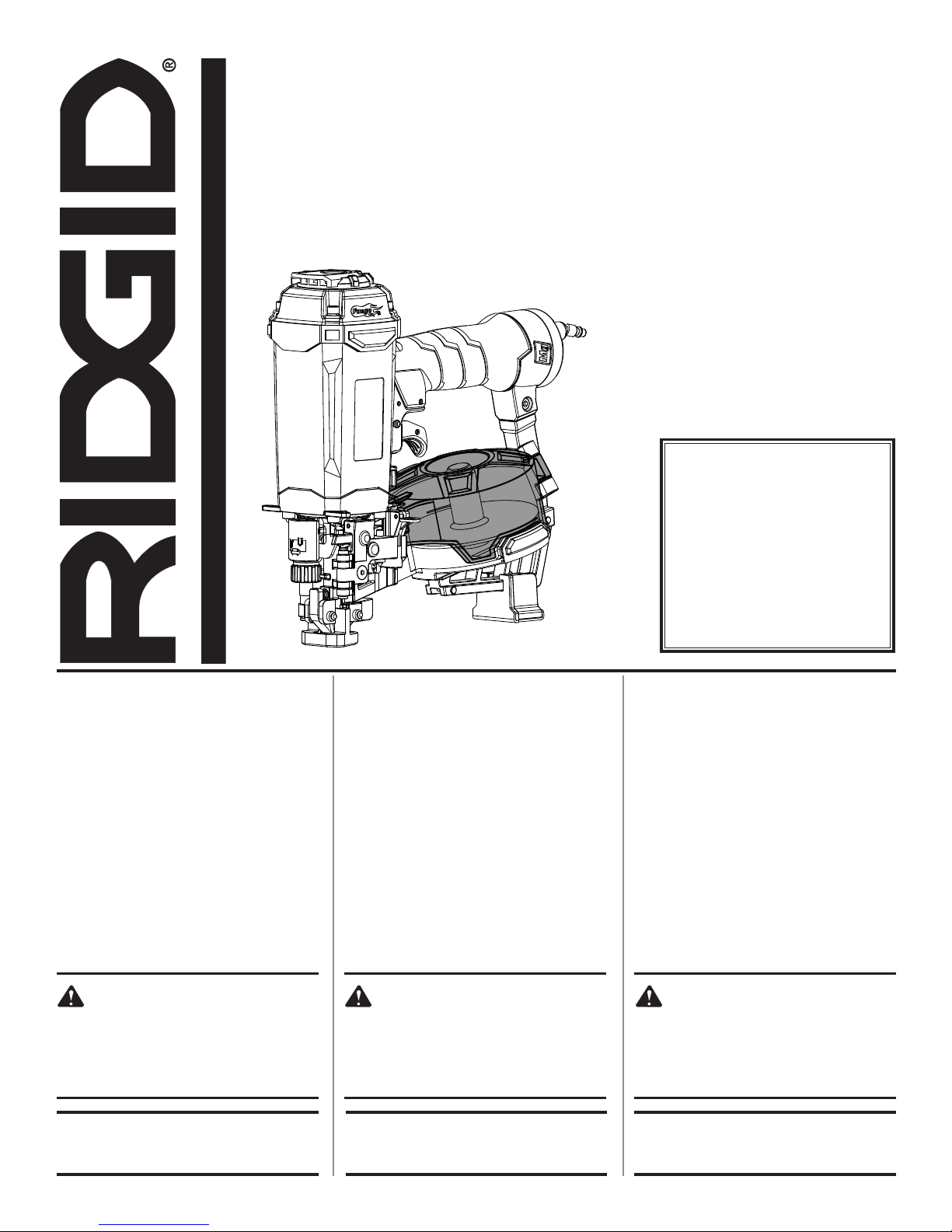
ROOFING COIL NAILER
CLOUEUSE À TOITURE À BOBINE
CLAVADORA DE TECHAR DE BOBINA
R175RNE
To register your RIDGID
c
n
i
1
-
4
/
3
product, please visit:
http://register.RIDGID.com
Pour enregistrer votre
produit de RIDGID,
s’il vous plaît la visite:
http://register.RIDGID.com
TABLE OF CONTENTS
****************
General Safety Rules .......................... 2
Specific Safety Rules ......................3-4
Symbols ..............................................5
Glossary of Terms ...............................6
Features .............................................. 7
Assembly ............................................ 8
Operation .......................................8-11
Maintenance ................................12-13
Accessories ...................................... 13
Troubleshooting ................................ 14
Figure Numbers (Illustrations) ......15-17
Parts Ordering and
Service ................................Back page
WARNING:
To reduce the risk of injury, the
user must read and understand
the operator’s manual before
using this product.
TABLE DES MATIÈRES
****************
Règles de sécurité générales ..........2-3
Règles de sécurité particulières ......3-4
Symboles ............................................5
Glossaire .............................................6
Caractéristiques ................................7
Assemblage ........................................ 8
Utilisation .......................................8-11
Entretien ......................................12-13
Accessoires ...................................... 13
Dépannage ....................................... 14
Figure numéros (illustrations) .....15-17
Commande de pièces et
dépannage ........................Page arrière
AVERTISSEMENT :
Pour réduire les risques de
blessures, l’utilisateur doit lire
et veiller à bien comprendre
le manuel d’utilisation avant
d’utiliser ce produit.
Para registrar su producto
de RIDGID, por favor visita:
http://register.RIDGID.com
ÍNDICE DE CONTENIDO
****************
Reglas de seguridad generales ..... 2-3
Reglas de seguridad específicas ... 3-4
Símbolos ............................................5
Glosario de términos .........................6
Características ...................................7
Armado ..............................................8
Funcionamiento ........................... 8-11
Mantenimiento ........................... 12-13
Accesorios .......................................13
Solución de problemas ....................14
Figura numeras (ilustraciones) ... 15-17
Pedidos de piezas y
servicio .........................Pág. posterior
ADVERTENCIA:
Para reducir el riesgo de
lesiones, el usuario debe leer
y comprender el manual del
operador antes de usar este
producto.
SAVE THIS MANUAL FOR
FUTURE REFERENCE
CONSERVER CE MANUEL
POUR FUTURE RÉFÉRENCE
GUARDE ESTE MANUAL
PARA FUTURAS CONSULTAS

GENERAL SAFETY RULES
DANGER:
READ AND UNDERSTAND TOOL LABELS AND
MANUAL. Failure to follow warnings could result
in DEATH or SERIOUS INJURY.
SAVE THESE INSTRUCTIONS
WORK AREA
Keep your work area clean and well lit. Cluttered
benches and dark areas invite accidents.
Do not operate power tools in explosive atmospheres,
such as in the presence of flammable liquids, gases,
or dust. Power tools create sparks which may ignite the
dust or fumes.
Keep bystanders, children, and visitors away while
operating a power tool. Distractions can cause you to
lose control.
PERSONAL SAFETY
Eye protection which conforms to ANSI specifications
and provides protection against flying particles both
from the FRONT and SIDE should ALWAYS be worn
by the operator and others in the work area when
loading, operating or servicing this tool. Eye protection
is required to guard against flying fasteners and debris,
which could cause severe eye injury.
The employer and/or user must ensure that proper eye
protection is worn. We recommend Wide Vision Safety
Mask for use over eyeglasses or standard safety glasses
that provide protection against flying particles both from
the front and side. Always wear eye protection with side
shields marked to comply with ANSI Z87.1.
Additional safety protection will be required in some
environments. For example, the working area may
include exposure to noise level which can lead to hearing
damage. The employer and user must ensure that any
necessary hearing protection is provided and used by the
operator and others in the work area. Some environments
will require the use of head protection equipment. When
required, the employer and user must ensure that head
protection conforming to ANSI Z89.1-1997 is used.
Stay alert, watch what you are doing and use common
sense when operating a power tool. Do not use tool
while tired or under the influence of drugs, alcohol,
or medication. A moment of inattention while operating
power tools may result in serious personal injury.
Dress properly. Do not wear loose clothing or jewelry.
Contain long hair. Keep your hair, clothing, and gloves
away from moving parts. Loose clothes, jewelry, or long
hair can be caught in moving parts.
Keep fingers away from trigger when not driving
fasteners to avoid accidental firing.
Do not overreach. Keep proper footing and balance
at all times. Proper footing and balance enables better
control of the tool in unexpected situations.
Use safety equipment. Always wear eye protection.
Dust mask, nonskid safety shoes, hard hat, or hearing
protection must be used for appropriate conditions.
Do not use on a ladder or unstable support. Stable
footing on a solid surface enables better control of the
tool in unexpected situations.
TOOL USE AND CARE
Do not force tool. Use the correct tool for your
application. The correct tool will do the job better and
safer at the rate for which it is designed.
Do not use tool if trigger does not actuate properly.
Any tool that cannot be controlled with the trigger is
dangerous and must be repaired.
Check operation of the workpiece contact mechanism
frequently. Do not use the tool if the workpiece contact
mechanism is not working correctly as accidental driving
of a fastener may result. Do not interfere with the proper
operation of the workpiece contact mechanism.
Store idle tools out of the reach of children and other
untrained persons. Tools are dangerous in the hands of
untrained users.
Maintain tools with care. Follow maintenance
instructions. Properly maintained tools are easier to
control.
Check for misalignment or binding of moving parts,
breakage of parts, and any other condition that may
affect the tool’s operation. If damaged, have the tool
serviced before using. Many accidents are caused by
poorly maintained tools.
Use only fasteners that are recommended for your
model.
Keep the tool and its handle dry, clean and free from
oil and grease. Always use a clean cloth when cleaning.
Never use brake fluids, gasoline, petroleum-based
products, or any strong solvents to clean your tool.
Following this rule will reduce the risk of loss of control
and deterioration of the enclosure plastic.
SERVICE
Tool service must be performed only by qualified
repair personnel. Service or maintenance performed by
unqualified personnel may result in a risk of injury.
When servicing a tool, use only identical replacement
parts. Follow instructions in the Maintenance section
of this manual. Use of unauthorized parts or failure to
follow Maintenance instructions may create a risk of
injury.
2 – English

SPECIFIC SAFETY RULES
Know your pneumatic tool. Read operator’s manual
carefully. Learn its applications and limitations, as well
as the specific potential hazards related to this tool.
Following this rule will reduce the risk of electric shock,
fire, or serious injury.
Always wear eye protection with side shields marked
to comply with ANSI Z87.1. Failure to do so could result
in objects being thrown into your eyes resulting in possible
serious injury.
Protect your lungs. Wear a face or dust mask if the
operation is dusty. Following this rule will reduce the risk
of serious personal injury.
Protect your hearing. Wear hearing protection during
extended periods of operation. Following this rule will
reduce the risk of serious personal injury.
Make sure the hose is free of obstructions or snags.
Entangled or snarled hoses can cause loss of balance or
footing and may become damaged.
Use the tool only for its intended use. Do not discharge
fasteners into open air.
Use the pneumatic tool only for the purpose for which
it was designed.
Use only the fasteners recommended for this tool.
Use of the wrong fasteners could result in poor fastener
feeding, jammed fasteners, and nails leaving the tool at
erratic angles. If fasteners are not feeding smoothly and
properly, discontinue their use immediately. Jammed
and improperly feeding fasteners could result in serious
personal injury.
Never use this tool in a manner that could cause a
fastener to be directed toward anything other than
the workpiece.
Do not use the tool as a hammer.
Always carry the tool by the handle. Never carry the
tool by the air hose.
Do not alter or modify this tool from the original design
or function without approval from the manufacturer.
Always be aware that misuse and improper handling
of this tool can cause injury to yourself and others.
Never clamp or tape the trigger or workpiece contact
in an actuated position.
Never leave a tool unattended with the air hose
attached.
Do not operate this tool if it does not contain a legible
warning label.
Do not continue to use a tool that leaks air or does
not function properly.
OPERATION
Always assume that the tool contains fasteners.
Do not carry the tool from place to place holding the
trigger. Accidental discharge could result.
Always handle the tool with care:
• Respect the tool as a working implement.
• Never engage in horseplay.
• Never pull the trigger unless nose is directed toward
the work.
• Keep others a safe distance from the tool while tool is in
operation as accidental actuation may occur, possibly
causing injury.
Choice of triggering method is important. Check
manual for triggering options.
Pneumatic tools are designed for single-hand use. Do
not hold the tool by the front of the magazine. Do not put
hands, head, or other parts of your body near the bottom
of the magazine where the nail exits the tool, as serious
personal injury could result.
Do not point the tool toward yourself or anyone
whether it contains fasteners or not.
Do not actuate the tool unless you intend to drive a
fastener into the workpiece.
Always ensure that the workpiece contact is fully
positioned above the workpiece. Positioning the
workpiece contact only partially above the workpiece
could cause the fastener to miss the workpiece completely
and result in serious personal injury.
Do not drive fasteners near edge of material. The
workpiece may split causing the fastener to ricochet,
injuring you or a co-worker. Be aware that the nail may
follow the grain of the wood, causing it to protrude
unexpectedly from the side of the work material.
Keep hands and body parts clear of immediate work
area. Hold workpiece with clamps when necessary to
keep hands and body out of potential harm. Be sure the
workpiece is properly secured before pressing the nailer
against the material. The workpiece contact may cause
the work material to shift unexpectedly.
Keep face and body parts away from back of the tool
cap when working in restricted areas. Sudden recoil
can result in impact to the body, especially when nailing
into hard or dense material.
During normal use the tool will recoil immediately
after driving a fastener. This is a normal function of
the tool. Do not attempt to prevent the recoil by holding
the nailer against the work. Restriction to the recoil can
result in a second fastener being driven from the nailer.
Grip the handle firmly, let the tool do the work and do not
place second hand on top of tool or near exhaust at any
time. Failure to heed this warning can result in serious
personal injury.
3 – English

SPECIFIC SAFETY RULES
Do not drive fasteners on top of other fasteners or with
the tool at an overly steep angle as this may cause
deflection of fasteners which could cause injury.
Do not drive fasteners close to the edge of the
workpiece as the wood may split, allowing the
fastener to be deflected possibly causing injury.
AIR SUPPLY AND CONNECTIONS
Do not use oxygen, combustible gases or bottled
gases as a power source for this tool as tool will
explode, possibly causing injury or death.
Do not use with an air compressor which can
potentially exceed 200 psi as tool may burst, possibly
causing injury.
The connector on the tool must not hold pressure
when air supply is disconnected. If an incorrect fitting
is used, the tool can remain charged with air after
disconnecting and thus will be able to drive a fastener
even after the air line is disconnected, possibly causing
injury.
Always disconnect air supply:
• Before making adjustments
• When servicing the tool
• When clearing a jam
• When tool is not in use
• When moving to a different work area, as accidental
actuation may occur, possibly causing injury.
LOADING TOOL
Do not load the tool with fasteners when any one of
the operating controls is activated.
When loading tool:
Never place a hand or any part of body in fastener
discharge area of tool.
Never point tool at anyone.
Do not pull the trigger or depress the workpiece
contact as accidental actuation may occur, possibly
causing injury.
SAVE THESE INSTRUCTIONS
Refer to them frequently and use them to instruct others
who may use this tool. If you loan someone this tool, loan
them these instructions also.
4 – English
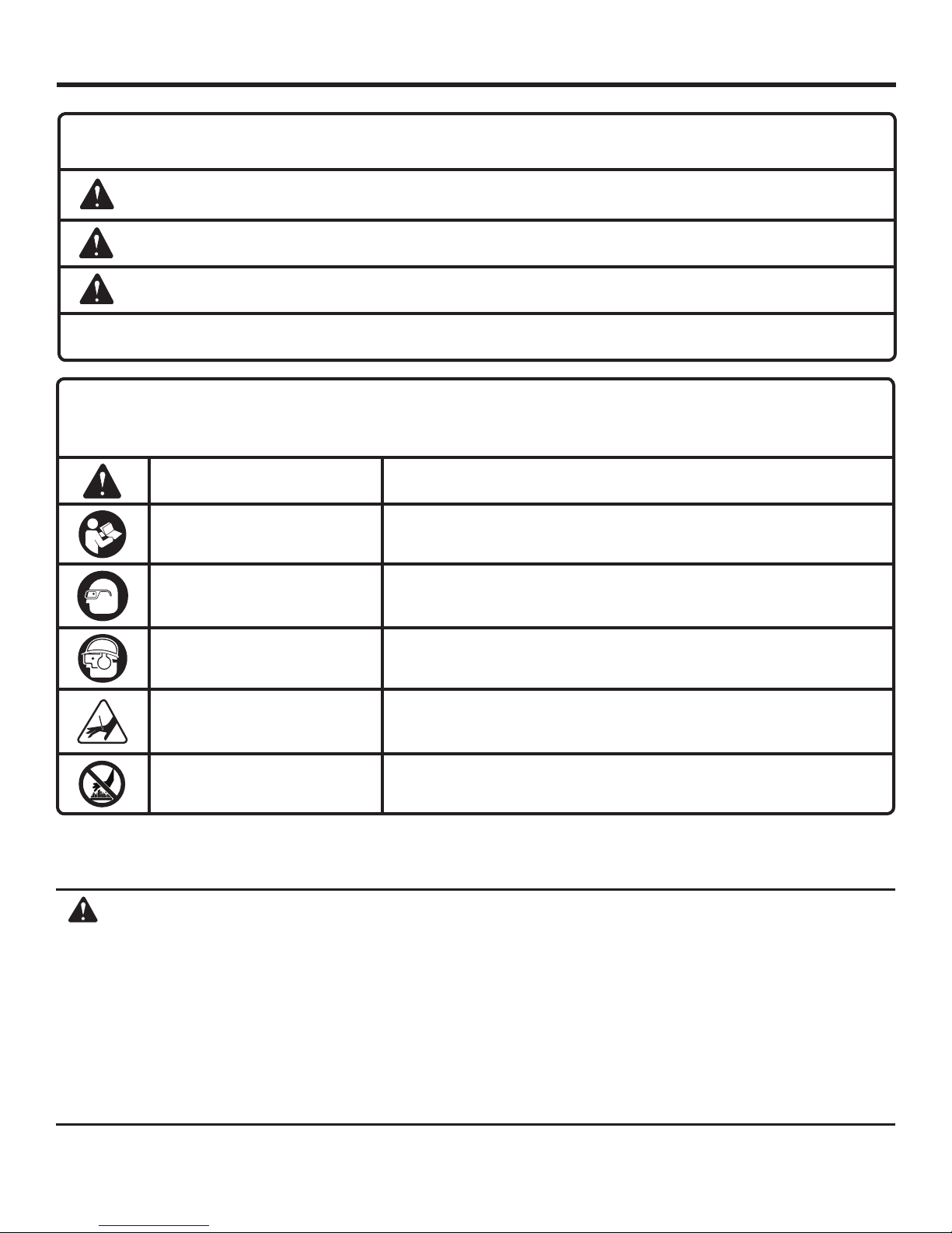
SYMBOLS
The following signal words and meanings are intended to explain the levels of risk associated with this product.
SYMBOL SIGNAL MEANING
DANGER:
WARNING:
CAUTION:
NOTICE:
Some of the following symbols may be used on this tool. Please study them and learn their meaning. Proper interpretation of these symbols will allow you to operate the tool better and safer.
SYMBOL NAME DESIGNATION/EXPLANATION
Safety Alert Indicates a potential personal injury hazard
Read Operator’s Manual
Eye Protection
Indicates an imminently hazardous situation, which, if not avoided, will result in death
or serious injury.
Indicates a potentially hazardous situation, which, if not avoided, could result in death
or serious injury.
Indicates a potentially hazardous situation, which, if not avoided, may result in minor or
moderate injury.
Without Safety Alert Symbol) Indicates important information not related to an injury
hazard, such as a situation that may result in property damage.
To reduce the risk of injury, user must read and understand operator’s
manual before using this product.
Always wear eye protection with side shields marked to comply with
ANSI Z87.1.
Eye, Ear and Head Protection
Keep Hands Away Keep hands and body away from the discharge area of the tool.
Hot Surface To reduce the risk of injury or damage, avoid contact with any hot surface.
CALIFORNIA PROPOSITION 65
WARNING:
This product and some dust created by power sanding, sawing, grinding, drilling, and other construction activities
may contain chemicals, including lead, known to the State of California to cause cancer, birth defects, or other
reproductive harm. Wash hands after handling.
Some examples of these chemicals are:
• lead from lead-based paints,
• crystalline silica from bricks and cement and other masonry products, and
• arsenic and chromium from chemically-treated lumber.
Your risk from exposure to these chemicals varies, depending on how often you do this type of work. To reduce
your exposure, work in a well-ventilated area and with approved safety equipment, such as dust masks that are
specially designed to filter out microscopic particles.
Always wear other personal protective equipment such as hearing
protection and a hard hat when needed.
5 – English

GLOSSARY OF TERMS
Activate (operating controls)
To move an operating control so that it is in a position
that allows the tool to be actuated or that satisfies one
requirement for the tool to be actuated.
Actuate (tool)
To cause movement of the tool component(s) intended to
drive a fastener.
Actuation system
The use of a trigger, workpiece contact and/or other
operating control, separately or in some combination or
sequence, to actuate the tool.
• Single sequential actuation
An actuation system in which there is more than one
operating control and the operating controls must
be activated in a specific sequence to actuate the
tool. Additional actuation can occur when a specific
operating control, other than a workpiece contact, is
released and re-activated.
• Contact actuation
An actuation system in which there is more than one
operating control and the operating controls can be
activated in any sequence to actuate the tool. Additional
actuation can occur when any operating control is
released and re-activated.
Air inlet port
In an air tool, the opening to which the compressed air supply
is connected, usually by means of a threaded fitting.
Fastener
A staple, pin, brad, nail, or other fastening device which is
designed and manufactured for use in the tools within the
scope of this standard.
Jam
An obstruction in the feed or drive areas of the tool.
Maximum air pressure
The maximum allowable pressure of the compressed air, as
specified by the manufacturer, for operating a tool.
Operating control
A control that separately, or as part of an actuation system,
can cause the actuation of a tool.
Trigger
A tool operating control activated by a tool operator’s
fingers.
Workpiece
The intended object into which a fastener is to be driven
by a tool.
Workpiece contact
An operating control element or assembly on the tool
intended to be activated by the material to be fastened.
6 – English

FEATURES
PRODUCT SPECIFICATIONS
Operating Pressure............................................. 70-120 psi
Magazine Capacity ................................................ 120 nails
Air Consumption.............................0.06 ft3/cycle at 100 psi
Air Inlet .............................................................. 1/4 in. NPT
Weighted sound impulse power level ..................113.7 dBA
Emission sound pressure level ............................100.7 dBA
Weight ......................................................................4.5 lbs.
KNOW YOUR ROOFING COIL NAILER
See Figure 1, page 15.
The safe use of this product requires an understanding of
the information on the tool and in this operator’s manual as
well as a knowledge of the project you are attempting. Before
use of this product, familiarize yourself with all operating
features and safety rules.
ADJUSTABLE EXHAUST
The exhaust can be adjusted to a variety of positions
depending on operator preference.
DEPTH OF DRIVE ADJUSTMENT
The tool-free depth of drive adjustment lets the operator
select precise driving depth of the fastener.
DRY-FIRE LOCKOUT
The dry-fire lockout feature keeps the tool from operating
when fasteners are low in the magazine to prevent missing
fasteners in the nail pattern and extend motor life.
EZ LOAD™ WITH OFFSET MAGAZINE
The EZ Load feature makes reloading quick and easy. The
offset magazine has two adjustment positions to accept
various nail sizes.
HEX GRIP
Ergonomic handle with Hex Grip™ overmold improves
comfort and grip.
™
IN-HANDLE AIR FILTER
The self-cleaning in-handle air filter helps keep debris out
to extend the life of the tool.
INTERNAL PISTON CATCH
The internal piston catch delivers consistent driving power.
MUFFLER
The muffler reduces noise during operation.
QUICK-CONNECT SWIVEL CONNECTOR
The quick-connect swivel connector helps prevent hose
tangles.
REPLACEABLE NOSEPIECE WITH CARBIDE
INSERTS
This feature makes maintenance easier to perform and
extends the life of the tool.
SELECTABLE TRIGGER
The selectable trigger lets the operator choose between
Contact Actuation for higher productivity and Single
Sequential Actuation for precise fastener placement.
SHINGLE GUIDE
A removable, tool-free shingle guide is included with the
nailer for precise placement of shingles.
7 – English
ASSEMBLY
WARNING:
Do not use this product if it is not completely
assembled or if any parts appear to be missing or
damaged. Use of a product that is not properly and
completely assembled or with damaged or missing
parts could result in serious personal injury.
If any parts are damaged or missing, please call 1-866-539-1710 for assistance.
WARNING:
Do not attempt to modify this product or create
accessories or attachments not recommended
for use with this product. Any such alteration
or modification is misuse and could result in a
hazardous condition leading to possible serious
personal injury.
OPERATION
APPLICATIONS
DANGER:
Do not use oxygen, combustible gases or bottled
gases as a power source for this tool. The tool will
explode and cause death or serious injury.
WARNING:
Do not allow familiarity with tools to make you
careless. Remember that a careless fraction of a
second is sufficient to inflict severe injury.
You may use this tool for the purposes listed below:
Asphalt & Fiberglass Shingles
Waterproof Tar Paper
Roofing Felt
House Wrap
Cement Board
Insulation Board
Metal Drip Edges
Siding
Vapor Barrier
WARNING:
Always wear eye protection with side shields
marked to comply with ANSI Z87.1. Failure to do
so could result in objects being thrown into your
eyes resulting in possible serious injury.
WARNING:
Disconnect the tool from the air supply before
leaving the work area, moving the tool to another
location, or handing the tool to another person.
Failure to do so could result in serious personal
injury.
WARNING:
Always wear eye protection. Eye protection does
not fit all operators in the same way. Make sure the
eye protection chosen has side shields or provides
protection from flying debris both from the front
and sides.
8 – English
OPERATION
PREPARING THE TOOL FOR USE
See Figure 2, page 15.
Under normal use conditions, the tool should be lubricated
before connecting the tool to an air supply. Add 30 drops
of oil into the swivel connector to lubricate the tool before
its first use. After the initial lubrication, maintain the tool by
adding oil daily. Add 10 drops once daily with minimal use, or
twice daily with heavy use. Only add oil as necessary. Excess
oil will collect inside the tool and will be visible around the
upper and lower exhaust.
Before connecting the tool, check the air compressor gauge
to be sure it is functioning within the proper range of 70120 psi.
ADJUSTING THE EXHAUST
See Figure 3, page 15.
The adjustable exhaust on the end cap of the tool allows
the operator to direct the exhaust according to operator
preference.
To adjust, turn the exhaust cap in the desired direction.
CONNECTING THE TOOL TO AN AIR SUPPLY
See Figure 4, page 15.
WARNING:
Disconnect the tool from the air supply before
leaving the work area, moving the tool to another
location, or handing the tool to another person.
Failure to do so could result in serious personal
injury.
WARNING:
Do not climb rigging or scaffolding while carrying
a tool that is connected to an air hose. Doing so
could result in serious personal injury.
Connect the tool to the air supply with a 1/4 in. female quick
connector. A 3/8 in. female quick connector may be used
in situations where a 1/4 in. supply line is not available. For
maximum tool performance, a 3/8 in. supply line and fittings
are required.
ADJUSTING THE OFFSET MAGAZINE
See Figures 5 - 6, pages 15 and 16.
The EZ Load™ feature is designed for quick and easy
reloads. To prevent jamming, always adjust the magazine
to the correct position for the size nail you are using. There
is an adjustment indicator inside the magazine to help you
choose the right position.
To adjust the magazine, pull up on the spool and rotate it
until the nail tray rests in place in the desired position. Rotate
it counterclockwise to lower the nail tray. Turn it clockwise
to raise the nail tray.
Position Nail Size
Position 1 3/4 in., 7/8 in., 1 in., 1-1/4 in.
Position 2 1-1/4 in., 1-3/4 in.
LOADING THE TOOL WITH NAILS
See Figures 7 - 9, page 16.
DANGER:
Do not use oxygen, combustible gases or bottled
gases as a power source for this tool. The tool will
explode and cause death or serious injury.
This tool is designed to operate on clean, dry compressed air
at regulated pressures between 70 and 120 psi . The correct
air pressure is the lowest pressure that will do the job.
NOTE: Air pressure that is higher than 120 psi may damage
the tool.
The tool and air hose must have a hose coupling that allows
all pressure to be removed from the tool when the coupling
is disconnected.
WARNING:
Always use a coupling that discharges all the
compressed air in the tool at the time the fitting or
hose coupling is disconnected. Using a coupling
that does not discharge the compressed air could
cause unintended operation and serious personal
injury.
WARNING:
The tool’s driving mechanism may cycle when the
tool is first connected to the air supply. Always
connect the tool to a pressurized air supply before
loading nails to prevent injury from unintended
cycling. Always make sure the tool’s magazine
is empty at the beginning of each work session,
before connecting to an air supply.
WARNING:
Keep the tool pointed away from yourself and
others when loading nails. Failure to do so could
result in possible serious personal injury.
9 – English
OPERATION
WARNING:
Use only the nails recommended for use with this
tool (refer to the Fastener Guide). The use of any
other nails can result in tool malfunction, leading
to serious injuries.
WARNING:
Never load nails with the workpiece contact or
trigger activated. Doing so could result in possible
serious personal injury.
Connect the tool to the air supply.
Depress the feeder cover latch and open the cover.
Open the magazine cover.
Slide the coil of nails onto the spool with the nails pointing
down. Uncoil about 3 in. of nails from the coil of roofing
nails.
Insert the first nail into the feeder. The first nail should sit
in the nose of the tool.
Position the second nail between the guides. The nail
heads should lie in the track.
Close the magazine cover.
Securely close the feeder cover, snapping it into place.
Be sure that the feeder cover is locked before resuming
operation.
NOTE: Take care not to pinch fingers in the spring area
of the latch when closing the feeder cover
.
USING THE SELECTABLE TRIGGER
See Figures 10 - 11, pages 16-17.
WARNING:
Never wedge or hold back the workpiece contact
mechanism during operation of the tool. Doing so
could result in possible serious injury.
This tool is shipped from the factory with a selectable trigger
set in the Single Sequential Actuation mode. The selectable
trigger can also be set for Contact Actuation mode.
SINGLE SEQUENTIAL ACTUATION MODE
Single sequential actuation provides the most accurate
fastener placement.
Disconnect the tool from the air supply.
Push the actuation mode selector to Position A.
WARNING:
The nailer will not function properly if the selector
is not pushed all the way to either position A or
B. Always assure the selector is seated properly
to avoid an unexpected fastener discharge and
possible serious personal injury.
Reconnect the tool to the air supply.
Grip the tool firmly to maintain control. Position the nose
of the tool onto the work surface.
Push the tool against the work surface to depress the
workpiece contact.
Squeeze the trigger to drive a fastener.
Allow the tool to recoil away from the work surface as the
fastener is driven.
Always remove your finger from the trigger when the
desired number of nails has been driven.
CONTACT ACTUATION MODE
Contact actuation allows very fast repetitive fastener placement.
Disconnect the tool from the air supply.
Push the actuation mode selector to Position B.
Reconnect the tool to the air supply.
Grip the tool firmly to maintain control.
Squeeze and hold the trigger. Push the tool against the
work surface to depress the workpiece contact and drive
a fastener.
Allow the tool to recoil away from the work surface as the
fastener is driven.
Always remove your finger from the trigger when the
desired number of nails has been driven.
NOTE: In Contact Actuation Mode, the tool may also be
operated by depressing the workpiece contact against the
surface and squeezing the trigger.
WARNING:
During normal use the tool will recoil immediately
after driving a fastener. This is a normal function
of the tool. Do not attempt to prevent the recoil
by holding the nailer against the work. Restriction
to the recoil can result in a second fastener being
driven from the nailer. Grip the handle firmly, let
the tool do the work, and do not place second
hand on top of tool or near exhaust at any time.
Failure to heed this warning can result in serious
personal injury.
10 – English

OPERATION
SETTING THE AIR PRESSURE
The amount of air pressure required will depend on the size
of the nail and the workpiece material.
Begin testing the depth of drive by driving a test nail into
the same type of workpiece material used for the actual job.
Drive a test nail with the air pressure set at 90-95 psi. Raise
or lower the air pressure to find the lowest setting that will
perform the job with consistent results.
It may be possible to achieve the desired depth with air
pressure adjustments alone. If finer adjustments are needed,
use the drive depth adjustment on the tool.
DRIVE DEPTH ADJUSTMENT
See Figure 12, page 17.
The driving depth of the nail may be adjusted. It is advisable
to test the depth on a scrap workpiece to determine the
required depth for the application.
To determine depth of drive, first adjust the air pressure and
drive a test nail. To achieve the desired depth, use the drive
depth adjustment on the tool.
Disconnect the tool from the air supply.
Turn the depth selector left or right to change the driving
depth.
Reconnect the tool to the air supply.
Drive a test nail after each adjustment until the desired
depth is set.
WARNING:
Disconnect the tool from the air supply before
removing nails or clearing a jammed fastener.
Failure to do so could result in serious personal
injury.
USING THE SHINGLE GUIDE
See Figure 13, page 17.
The shingle guide features tool-free adjustment. It is used
to place a shingle the desired distance from the front edge
of the previous row of shingles.
Disconnect the tool from the air supply.
With the nose of the tool pointed away from you, depress
the button on the back of the spacing selector.
Slide the guide to the desired measurement.
Release the button.
Reconnect the tool to the air supply.
REMOVING NAILS FROM THE TOOL
Disconnect the tool from the air supply.
Open the feeder cover and magazine cover (see Loading
the Tool with Nails).
Lift the nail strip from the spool and remove the remaining
coil of nails.
CLEARING A JAMMED FASTENER
See Figure 14, page 17.
If a nail becomes jammed in the tool, disconnect the air hose
and keep the tool pointed away from you while clearing the
jam.
Disconnect the tool from the air supply.
Open the feeder cover and magazine cover.
Remove fasteners from the tool.
Insert a #2 Phillips screwdriver into the driving
mechanism.
Tap the screwdriver gently with a hammer. The inserted
screwdriver should push the driver mechanism back,
freeing the nail jam.
Remove the bent nail, using needle-nose pliers if
necessary.
Reconnect the tool to the air supply.
Reload the tool with nails.
Close the magazine cover. Close the feeder cover
securely.
11 – English
MAINTENANCE
WARNING:
When servicing use only identical RIDGID
replacement parts. Use of any other parts may
create a hazard or cause product damage.
COLD WEATHER OPERATION
For cold weather operation, near and below freezing, the
moisture in the air line may freeze and prevent tool operation.
We recommend the use of air tool lubricant or permanent
antifreeze (ethylene glycol) as a cold weather lubricant.
WARNING:
Always wear eye protection with side shields
marked to comply with ANSI Z87.1. Failure to do
so could result in objects being thrown into your
eyes resulting in possible serious injury.
WARNING:
Disconnect the tool from the air supply before
performing maintenance. Failure to do so could
result in serious personal injury.
GENERAL MAINTENANCE
Avoid using solvents when cleaning plastic parts. Most
plastics are susceptible to damage from various types of
commercial solvents and may be damaged by their use. Use
clean cloths to remove dirt, dust, oil, grease, etc.
WARNING:
Do not at any time let brake fluids, gasoline,
petroleum-based products, penetrating oils, etc.,
come in contact with plastic parts. Chemicals can
damage, weaken or destroy plastic which may
result in serious personal injury.
LUBRICATION
Frequent, but not excessive, lubrication is required for
best performance. Oil for pneumatic fastening tools added
through the air line connection will lubricate the internal parts.
Do not use detergent oil or additives as these lubricants will
cause accelerated wear to the seals and bumpers in the
tool, resulting in poor tool performance and frequent tool
maintenance.
NOTICE:
Do not store tools in a cold weather environment
to prevent frost or ice formation on the tools’
operating valves and mechanisms that could cause
tool failure.
NOTE: Some commercial air line drying liquids are harmful
to “O” rings and seals. Do not use these low temperature
air dryers without checking compatibility.
AIR SUPPLY PRESSURE AND VOLUME
Air volume is as important as air pressure. The air volume
supplied to the tool may be inadequate because of undersize
fittings and hoses, or from the effects of dirt and water in the
system. Restricted air flow will prevent the tool from receiving
an adequate volume of air, even though the pressure reading
is high. The results will be a slow operation or reduced
driving power. Before evaluating tool problems for these
symptoms, trace the air supply from the tool to the supply
source for restrictive connectors, low points containing
water and anything else that would prevent full volume flow
of air to the tool.
REPLACING THE NOSEPIECE
See Figure 15, page 17.
The nosepiece with carbide inserts may be replaced when
the inserts are worn.
Remove the C-clip from the threaded end of the depth
of drive wheel, located below the nosepiece.
Turn the depth of drive adjustment wheel clockwise until
the nosepiece is unthreaded. Remove the nosepiece.
Place a new nosepiece over the threaded post as shown.
Turn the adjustment wheel counterclockwise and tighten
until the new nosepiece is fully seated.
Replace the C-clip.
12 – English

MAINTENANCE
REQUIRED DAILY CHECKLIST
See Figure 10, page 16.
Disconnect the air supply from the tool and remove all
fasteners.
Check all screws, nuts, bolts, and pins on the tool. If
any of these are loose, they must be tightened with the
appropriate size wrench.
Press the workpiece contact against a workpiece to
ensure that it moves smoothly.
With the workpiece contact depressed, pull the trigger.
The trigger should move smoothly, without binding.
While the tool is not loaded, connect the appropriate air
supply (at 70 psi) to the tool.
Select Single Sequential Actuation operation, Position A.
No air should leak from the tool.
• Without pulling the trigger, press the workpiece
contact against a workpiece several times. The tool
must not operate.
• With the workpiece contact not engaged on the
workpiece, point the tool down and away and pull
the trigger several times. Hold the trigger in this
position for a minimum of 5 seconds. The tool must
not operate.
• Press the workpiece contact firmly against the
workpiece and pull the trigger. The tool must operate.
• With the workpiece contact still depressed, release
the trigger. The driver must return to its up position.
Select Contact Actuation operation, Position B.
• With the workpiece contact not engaged on the
workpiece, point the tool down and away. Pull the
trigger. The tool must not operate.
• Keeping the trigger fully depressed, push the workpiece
contact against a workpiece. The tool must operate.
If the tool successfully meets all the requirements in this
checklist, it is ready for use. Set the trigger on the tool
to operate in the manner that best fits your application.
Load the proper fasteners for the desired application.
Set the depth of drive according to the “Drive Depth
Adjustment” section in this manual. Repeat this checklist
before using the tool each day, or if the tool is dropped
or damaged in any way.
ACCESSORIES
To order parts and maintenance kits, call 1-866-539-1710.
Driver Maintenance Kit ....................................................................................................................................079006005701
Overhaul Kit .....................................................................................................................................................079006005702
Oil and Wrench Kit...........................................................................................................................................079006005704
WARNING:
Current attachments and accessories available for use with this tool are listed above. Do not use any attachments
or accessories not recommended by the manufacturer of this tool. The use of attachments or accessories not
recommended can result in serious personal injury.
13 – English

TROUBLESHOOTING
PROBLEM POSSIBLE CAUSE SOLUTION
Air leak near the top of the tool
or in the trigger area
Air leak near the bottom of the tool Inadequate lubrication
Tool does nothing or
operates sluggishly
Tool jams frequently Incorrect fasteners
Inadequate lubrication
Loose screws
Worn or damaged O-rings or seals
Loose screws
Worn or damaged O-rings or bumper
Inadequate air supply
Inadequate lubrication
Worn or damaged O-rings or bumper
Damaged fasteners
Loose magazine
Dirty magazine
Worn or damaged driver
Lubricate tool
Tighten screws
Install Overhaul Kit
Lubricate tool
Tighten screws
Install Overhaul Kit
Verify adequate air supply
Lubricate tool
Install Overhaul Kit
Verify that fasteners are the correct
size
Replace fasteners
Tighten screws
Clean magazine
Install Driver Maintenance Kit
NOTE: FIGURES (ILLUSTRATIONS) START ON PAGE 15
AFTER FRENCH AND SPANISH LANGUAGE SECTIONS.
This product has a 90-Day Satisfaction Guarantee Policy, as well as a
For Warranty and Policy details, please go to www.RIDGID.com
Three-year Limited Warranty.
or call (toll free) 1-866-539-1710.
14 – English
 Loading...