

Page 1
OPERATOR’S MANUAL
MANUEL D’UTILISATION
MANUAL DEL OPERADOR
4-1/2 in. ANGLE GRINDER
115 mm (4-1/2 po) MEULEUSE D’ANGLE
115 mm (4-1/2 pulg.) AMOLADOR ANGULAR
R1005
To register your RIDGID
product, please visit:
http://register.RIDGID.com
Pour enregistrer votre
produit de RIDGID,
s’il vous plaît la visite:
http://register.RIDGID.com
Para registrar su producto
de RIDGID, por favor visita:
http://register.RIDGID.com
Your angle grinder has been engineered and manufactured to our high standards for dependability, ease of operation, and
operator safety. When properly cared for, it will give you years of rugged, trouble-free performance.
WARNING:
To reduce the risk of injury, the user must read and understand the operator’s manual before using this product.
Thank you for buying a RIDGID® product.
SAVE THIS MANUAL FOR FUTURE REFERENCE
Cette meuleuse d’angle a été conçue et fabriquée conformément
à nos strictes normes de fiabilité, simplicité d’emploi et sécurité
d’utilisation. Correctement entretenue, elle vous donnera des
années de fonctionnement robuste et sans problèmes.
AVERTISSEMENT :
Pour réduire les risques de blessures, l’utilisateur doit
lire et veiller à bien comprendre le manuel d’utilisation
avant d’employer ce produit.
Merci d’avoir acheté un produit RIDGID®.
CONSERVER CE MANUEL POUR
FUTURE RÉFÉRENCE
Su amoladora angular ha sido diseñada y fabricada de conformidad
con nuestras estrictas normas para brindar fiabilidad, facilidad de
uso y seguridad para el operador. Con el debido cuidado, le brindará
muchos años de sólido funcionamiento y sin problemas.
ADVERTENCIA:
Para reducir el riesgo de lesiones, el usuario debe leer
y comprender el manual del operador antes de usar
este producto.
Le agradecemos la compra de un producto RIDGID®.
GUARDE ESTE MANUAL PARA
FUTURAS CONSULTAS
Page 2

TABLE OF CONTENTS
TABLE DES MATIÈRES / ÍNDICE DE CONTENIDO
Introduction ......................................................................................................................................................................2
Introduction / Introducción
General Safety Rules .....................................................................................................................................................3-4
Règles de sécurité générales / Reglas de seguridad generales
Specific Safety Rules .....................................................................................................................................................4-5
Règles de sécurité particulières / Reglas de seguridad específicas
Symbols ............................................................................................................................................................................ 6
Symboles / Símbolos
Electrical ........................................................................................................................................................................... 7
Caractéristiques électriques / Aspectos eléctricos
Features ............................................................................................................................................................................8
Caractéristiques / Características
Assembly .....................................................................................................................................................................8-10
Assemblage / Armado
Operation ...................................................................................................................................................................10-11
Utilisation / Funcionamiento
Maintenance ................................................................................................................................................................... 12
Entretien / Mantenimiento
Warranty .........................................................................................................................................................................13
Garantie / Garantía
Figure numbers (illustrations) ....................................................................................................................................14-16
Figure numéros (illustrations) / Figura numeras (ilustraciones)
Parts Ordering and Service ...............................................................................................................................Back Page
Commande de pièces et réparation / Pedidos de piezas y servicio ......................................................... Page arrière / Pág. posterior
INTRODUCTION
INTRODUCTION / INTRODUCCIóN
This product has many features for making its use more pleasant and enjoyable. Safety, performance, and dependability
have been given top priority in the design of this product making it easy to maintain and operate.
* * *
Ce produit offre de nombreuses fonctions destinées à rendre son utilisation plus plaisante et satisfaisante. Lors de la
conception de ce produit, l’accent a été mis sur la sécurité, les performances et la fiabilité, afin d’en faire un outil facile à
utiliser et à entretenir.
* * *
Este producto ofrece numerosas características para hacer más agradable y placentero su uso. En el diseño de este producto
se ha conferido prioridad a la seguridad, el desempeño y la fiabilidad, por lo cual se facilita su manejo y mantenimiento.
2
Page 3

GENERAL SAFETY RULES
WARNING:
Read all instructions. Failure to follow all
instructions listed below may result in electric
shock, fire and/or serious injury.
SAVE THESE INSTRUCTIONS
WORK AREA
Keep your work area clean and well lit. Cluttered
benches and dark areas invite accidents.
Do not operate power tools in explosive atmospheres,
such as in the presence of flammable liquids, gases,
or dust. Power tools create sparks which may ignite the
dust or fumes.
Keep bystanders, children, and visitors away while
operating a power tool. Distractions can cause you to
lose control.
ELECTRICAL SAFETY
Double insulated tools are equipped with a polarized
plug (one blade is wider than the other). This plug will
fit in a polarized outlet only one way. If the plug does
not fit fully in the outlet, reverse the plug. If it still
does not fit, contact a qualified electrician to install a
polarized outlet. Do not change the plug in any way.
Double insulation
wire grounded power cord and grounded power supply
system.
Avoid body contact with grounded surfaces such as
pipes, radiators, ranges, and refrigerators. There is an
increased risk of electric shock if your body is grounded.
Don’t expose power tools to rain or wet conditions.
Water entering a power tool will increase the risk of electric shock.
Do not abuse the cord. Never use the cord to carry the
tools or pull the plug from an outlet. Keep cord away
from heat, oil, sharp edges, or moving parts. Replace
damaged cords immediately. Damaged cords increase
the risk of electric shock.
When operating a power tool outside, use an outdoor
extension cord marked “W-A” or “W”. These cords
are rated for outdoor use and reduce the risk of electric
shock.
PERSONAL SAFETY
Stay alert, watch what you are doing and use common
sense when operating a power tool. Do not use tool
while tired or under the influence of drugs, alcohol,
or medication. A moment of inattention while operating
power tools may result in serious personal injury.
Dress properly. Do not wear loose clothing or jewelry.
Contain long hair. Keep your hair, clothing, and gloves
away from moving parts. Loose clothes, jewelry, or long
hair can be caught in moving parts.
eliminates the need for the three-
Avoid accidental starting. Be sure switch is off
before plugging in. Carrying tools with your finger on the
switch or plugging in tools that have the switch on invites
accidents.
Remove adjusting keys or wrenches before turning
the tool on. A wrench or a key that is left attached to a
rotating part of the tool may result in personal injury.
Do not overreach. Keep proper footing and balance
at all times. Proper footing and balance enables better
control of the tool in unexpected situations.
Use safety equipment. Always wear eye protection.
Dust mask, nonskid safety shoes, hard hat, or hearing
protection must be used for appropriate conditions.
Do not wear loose clothing or jewelry. Contain long
hair. Loose clothes, jewelry, or long hair can be drawn
into air vents.
Do not use on a ladder or unstable support. Stable
footing on a solid surface enables better control of the
tool in unexpected situations.
TOOL USE AND CARE
Use clamps or other practical way to secure and
support the workpiece to a stable platform. Holding
the work by hand or against your body is unstable and
may lead to loss of control.
Do not force tool. Use the correct tool for your
application. The correct tool will do the job better and
safer at the rate for which it is designed.
Do not use tool if switch does not turn it on or off. Any
tool that cannot be controlled with the switch is dangerous and must be repaired.
Disconnect the plug from power source before making
any adjustments, changing accessories, or storing the
tool. Such preventive safety measures reduce the risk of
starting the tool accidentally.
Store idle tools out of the reach of children and other
untrained persons. Tools are dangerous in the hands of
untrained users.
Maintain tools with care. Keep cutting tools sharp
and clean. Properly maintained tools with sharp cutting
edges are less likely to bind and are easier to control.
Check for misalignment or binding of moving parts,
breakage of parts, and any other condition that may
affect the tool’s operation. If damaged, have the tool
serviced before using. Many accidents are caused by
poorly maintained tools.
Use only accessories that are recommended by the
manufacturer for your model. Accessories that may be
suitable for one tool, may become hazardous when used
on another tool.
Keep the tool and its handle dry, clean and free from
oil and grease. Always use a clean cloth when clean-
ing. Never use brake fluids, gasoline, petroleum-based
products, or any strong solvents to clean your tool. Following this rule will reduce the risk of loss of control and
deterioration of the enclosure plastic.
3 - English
Page 4

GENERAL SAFETY RULES
SERVICE
Tool service must be performed only by qualified
repair personnel. Service or maintenance performed by
unqualified personnel may result in a risk of injury.
SPECIFIC SAFETY RULES
This power tool is intended to function as a grinder,
sander, wire brush, or polisher. Read all safety warnings,
instructions, illustrations and specifications provided
with this power tool. Failure to follow all instructions listed
below may result in electric shock, fire and/or serious injury.
Operations such as cutting-off are not recommended to
be performed with this power tool. Operations for which
the power tool was not designed may create a hazard and
cause personal injury.
Do not use accessories which are not specifically de-
signed and recommended by the tool manufacturer. Just
because the accessory can be attached to your power tool,
does not assure safe operation.
The rated speed of the accessory must be at least equal
to the maximum speed marked on the power tool. Ac-
cessories running faster than their RATED SPEED can break
and fly apart.
The outside diameter and the thickness of your acces-
sory must be within the capacity rating of your power
tool. Incorrectly sized accessories cannot be adequately
guarded or controlled.
The arbour size of wheels, flanges, backing pads or
any other accessory must properly fit the spindle of the
power tool. Accessories with arbour holes that do not match
the mounting hardware of the power tool will run out of balance, vibrate excessively and may cause loss of control.
Do not use a damaged accessory. Before each use in-
spect the accessory such as abrasive wheels for chips
and cracks, backing pad for cracks, tear or excess wear,
wire brush for loose or cracked wires. If power tool or
accessory is dropped, inspect for damage or install an
undamaged accessory. After inspecting and installing an
accessory, position yourself and bystanders away from
the plane of the rotating accessory and run the power
tool at maximum no-load speed for one minute. Damaged
accessories will normally break apart during this test time.
Wear personal protective equipment. Depending on
application, use face shield, safety goggles or safety
glasses. As appropriate, wear dust mask, hearing
protectors, gloves and workshop apron capable of
stopping small abrasive or workpiece fragments. he eye
protection must be capable of stopping flying debris
generated by various operations. The eye protection must
be capable of stopping flying debris generated by various
operations. The dust mask or respirator must be capable of
filtrating particles generated by your operation. Prolonged
exposure to high intensity noise may cause hearing loss.
Keep bystanders a safe distance away from work area.
When servicing a tool, use only identical replacement
parts. Follow instructions in the Maintenance section
of this manual. Use of unauthorized parts or failure to
follow Maintenance Instructions may create a risk of
shock or injury.
Anyone entering the work area must wear personal
protective equipment. Fragments of workpiece or of a
broken accessory may fly away and cause injury beyond
immediate area of operation.
Hold power tool by insulated gripping surfaces only,
when performing an operation where the cutting accessory may contact hidden wiring or its own cord. Cutting
accessory contacting a ²live² wire may make exposed metal
parts of the power tool ²live² and shock the operator.
Position the cord clear of the spinning accessory. If you
lose control, the cord may be cut or snagged and your hand
or arm may be pulled into the spinning accessory.
Never lay the power tool down until the accessory has
come to a complete stop. The spinning accessory may grab
the surface and pull the power tool out of your control.
Do not run the power tool while carrying it at your side.
Accidental contact with the spinning accessory could snag
your clothing, pulling the accessory into your body.
Regularly clean the power tool’s air vents. The motor’s
fan will draw the dust inside the housing and excessive
accumulation of powdered metal may cause electrical
hazards.
Do not operate the power tool near flammable materials.
Sparks could ignite these materials.
Do not use accessories that require liquid coolants. Using
water or other liquid coolants may result in electrocution or
shock.
Maintain a firm grip on the power tool and position your
body and arm to allow you to resist kickback forces.
Always use auxiliary handle, if provided, for maximum
control over kickback or torque reaction during start-up.
The operator can control torque reactions or kickback
forces, if proper precautions are taken.
Never place your hand near the rotating accessory.
Accessory may kickback over your hand.
Do not position your body in the area where power tool
will move if kickback occurs. Kickback will propel the tool
in direction opposite to the wheel’s movement at the point
of snagging.
Use special care when working corners, sharp edges etc.
Avoid bouncing and snagging the accessory. Corners,
sharp edges or bouncing have a tendency to snag the
rotating accessory and cause loss of control or kickback.
Do not attach a saw chain woodcarving blade or toothed
saw blade. Such blades create frequent kickback and loss
of control.
Use only wheel types that are recommended for your
power tool and the specific guard designed for the
4 - English
Page 5

SPECIFIC SAFETY RULES
selected wheel. Wheels for which the power tool was not
designed cannot be adequately guarded and are unsafe.
The guard must be securely attached to the power tool
and positioned for maximum safety, so the least amount
of wheel is exposed towards the operator. The guard
helps to protect operator from broken wheel fragments and
accidental contact with wheel.
Wheels must be used only for recommended applications.
For example: do not grind with the side of cut-off wheel.
Abrasive cut-off wheels are intended for peripheral grinding,
side forces applied to these wheels may cause them to
shatter.
Always use undamaged wheel flanges that are of correct
size and shape for your selected wheel. Proper wheel
flanges support the wheel thus reducing the possibility of
wheel breakage. Flanges for cut-off wheels may be different
from grinding wheel flanges.
Do not use worn down wheels from larger power tools.
Wheel intended for larger power tool is not suitable for the
higher speed of a smaller tool and may burst.
Do not use excessively oversized sanding disc paper.
Follow manufacturers recommendations, when selecting
sanding paper. Larger sanding paper extending beyond the
sanding pad presents a laceration hazard and may cause
snagging, tearing of the disc or kickback.
Do not allow any loose portion of the polishing bonnet
or its attachment strings to spin freely. Tuck away or
trim any loose attachment strings. Loose and spinning
attachment strings can entangle your fingers or snag on the
workpiece.
Be aware that wire bristles are thrown by the brush even
during ordinary operation. Do not overstress the wires by
applying excessive load to the brush. The wire bristles
can easily penetrate light clothing and/or skin.
If the use of a guard is recommended for wire brushing,
do not allow any interference of the wire wheel or brush
with the guard. Wire wheel or brush may expand in diameter
due to work load and centrifugal forces.
Always use proper guard with grinding wheel. A guard
protects operator from broken wheel fragments.
Know your power tool. Read operator’s manual carefully.
Learn its applications and limitations, as well as the
specific potential hazards related to this tool. Following
this rule will reduce the risk of electric shock, fire, or serious
injury.
Always wear eye protection with side shields marked
to comply with ANSI Z87.1. Failure to do so could result
in objects being thrown into your eyes, resulting in possible
serious injury.
Protect your lungs. Wear a face or dust mask if the
operation is dusty. Following this rule will reduce the risk
of serious personal injury.
Protect your hearing. Wear hearing protectors during
extended periods of operation. Following this rule will
reduce the risk of serious personal injury.
Inspect tool cords periodically and, if damaged, have
repaired at your nearest authorized service center.
Constantly stay aware of cord location. Following this
rule will reduce the risk of electric shock or fire.
Check damaged parts. Before further use of the tool, a
guard or other part that is damaged should be carefully
checked to determine that it will operate properly and
perform its intended function. Check for alignment of
moving parts, binding of moving parts, breakage of parts,
mounting, and any other conditions that may affect its
operation. A guard or other part that is damaged should
be properly repaired or replaced by an authorized service
center. Following this rule will reduce the risk of shock, fire,
or serious injury.
Make sure your extension cord is in good condition.
When using an extension cord, be sure to use one heavy
enough to carry the current your product will draw. A
wire gauge size (A.W.G.) of at least 14 is recommended
for an extension cord 50 feet or less in length. A cord
exceeding 100 feet is not recommended. If in doubt, use
the next heavier gauge. The smaller the gauge number,
the heavier the cord. An undersized cord will cause a drop
in line voltage resulting in loss of power and overheating.
Inspect for and remove all nails from lumber before using
this tool. Following this rule will reduce the risk of serious
personal injury.
If the power supply cord is damaged, it must be replaced
only by the manufacturer or by an authorized service center
to avoid risk.
Save these instructions. Refer to them frequently and use
them to instruct others who may use this tool. If you loan
someone this tool, loan them these instructions also.
WARNING:
Some dust created by power sanding, sawing, grinding, drilling, and other construction activities contains chemicals
known to cause cancer, birth defects or other reproductive harm. Some examples of these chemicals are:
•leadfromlead-basedpaints,
•crystallinesilicafrombricksandcementandothermasonryproducts,and
•arsenicandchromiumfromchemically-treatedlumber.
Your risk from these exposures varies, depending on how often you do this type of work. To reduce your exposure
to these chemicals: work in a well ventilated area, and work with approved safety equipment, such as those dust
masks that are specially designed to filter out microscopic particles.
5 - English
Page 6
SYMBOLS
The following signal words and meanings are intended to explain the levels of risk associated with this product.
SYMBOL SIGNAL MEANING
DANGER:
WARNING:
CAUTION:
CAUTION:
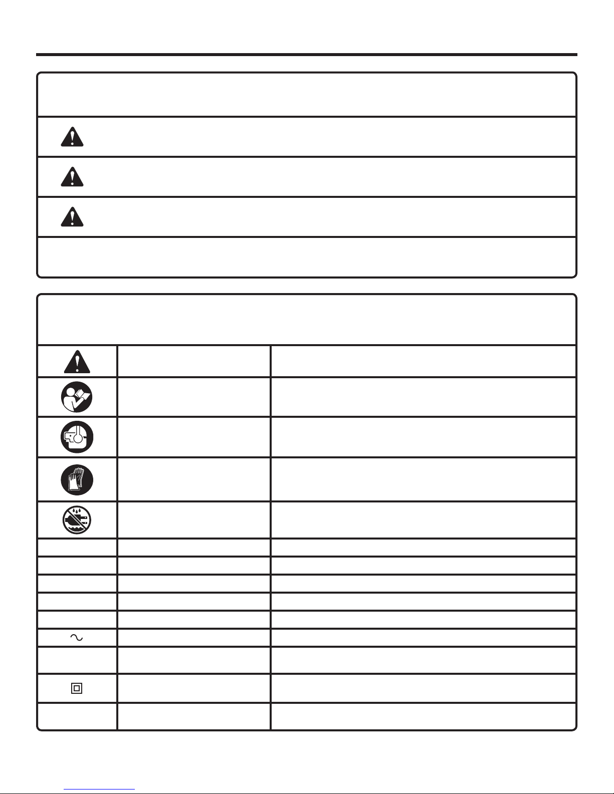
Some of the following symbols may be used on this product. Please study them and learn their meaning. Proper
interpretation of these symbols will allow you to operate the product better and safer.
SYMBOL NAME
Safety Alert Indicates a potential personal injury hazard.
Read Operator’s Manual
Indicates an imminently hazardous situation, which, if not avoided, will result
in death or serious injury.
Indicates a potentially hazardous situation, which, if not avoided, could result
in death or serious injury.
Indicates a potentially hazardous situation, which, if not avoided, may result in
minor or moderate injury.
(Without Safety Alert Symbol) Indicates a situation that may result in property
damage.
DESIGNATION/EXPLANATION
To reduce the risk of injury, user must read and understand
operator’s manual before using this product.
Eye and Hearing Protection
Wear gloves Always wear gloves when operating.
Wet Conditions Alert Do not expose to rain or use in damp locations.
V Volts Voltage
A Amperes Current
Hz Hertz Frequency (cycles per second)
W Watt Power
min Minutes Time
Alternating Current Type of current
n
o
.../min Per Minute Revolutions, strokes, surface speed, orbits etc., per minute
No Load Speed Rotational speed, at no load
Class II Tool Double-insulated construction
Always wear eye protection with side shields marked to comply
with ANSI Z87.1 along with hearing protection.
6 - English
Page 7

ELECTRICAL
DOUBLE INSULATION
Double insulation is a concept in safety in electric power
tools, which eliminates the need for the usual three-wire
grounded power cord. All exposed metal parts are isolated
from the internal metal motor components with protecting
insulation. Double insulated products do not need to be
grounded.
WARNING:
The double insulated system is intended to protect
the user from shock resulting from a break in the
product’s internal wiring. Observe all normal safety
precautions to avoid electrical shock.
NOTE: Servicing of a product with double insulation requires
extreme care and knowledge of the system and should be
performed only by a qualified service technician. For service,
we suggest you return the product to your nearest authorized
service center for repair. Always use original factory replacement parts when servicing.
ELECTRICAL CONNECTION
This product has a precision-built electric motor. It should
be connected to a power supply that is 120 volts, AC only
(normal household current), 60 Hz. Do not operate this
product on direct current (DC). A substantial voltage drop
will cause a loss of power and the motor will overheat. If
the product does not operate when plugged into an outlet,
double-check the power supply.
EXTENSION CORDS
When using a power tool at a considerable distance from
a power source, be sure to use an extension cord that has
the capacity to handle the current the product will draw. An
undersized cord will cause a drop in line voltage, resulting in
overheating and loss of power. Use the chart to determine
the minimum wire size required in an extension cord. Only
round jacketed cords listed by Underwriter’s Laboratories
(UL) should be used.
When working outdoors with a product, use an extension
cord that is designed for outside use. This type of cord is
designated with “WA” or “W” on the cord’s jacket.
Before using any extension cord, inspect it for loose or
exposed wires and cut or worn insulation.
**Ampere rating (on product data plate)
0-2.0 2.1-3.4 3.5-5.0 5.1-7.0 7.1-12.0 12.1-16.0
Cord Length Wire Size (A.W.G.)
25' 16 16 16 16 14 14
50' 16 16 16 14 14 12
100' 16 16 14 12 10 —
**Used on 12 gauge - 20 amp circuit.
NOTE: AWG = American Wire Gauge
WARNING:
Keep the extension cord clear of the working area.
Position the cord so that it will not get caught on
lumber, tools, or other obstructions while you are
working with a power tool. Failure to do so can
result in serious personal injury.
WARNING:
Check extension cords before each use. If
damaged replace immediately. Never use tool with
a damaged cord since touching the damaged area
could cause electrical shock resulting in serious
injury.
7 - English
Page 8

FEATURES
PRODUCT SPECIFICATIONS
Grinding Wheel Capacity .......................................4-1/2 in.
Spindle Thread ........................................ 5/8 in. x 11 UNC
No Load Speed .................................. 10,000 r/min. (RPM)
Input ..................................120 V, AC only, 60 Hz, 7 Amps
Net Weight .............................................................. 4.7 lbs.
KNOW YOUR ANGLE GRINDER
See Figure 1, page 14.
The safe use of this product requires an understanding of
the information on the product and in this operator’s manual
as well as a knowledge of the project you are attempting.
Before use of this product, familiarize yourself with all
operating features and safety rules.
EXTERNALLY ACCESSIBLE BRUSHES
Externally accessible brushes extend the life of the grinder.
ILLUMINATED PLUG
This grinder is equipped with a plug that illuminates when
power is supplied to the tool. This allows the operator to
easily identify live tools.
ASSEMBLY
LOCK-OFF / LOCK-ON BUTTON
The combination lock-off / lock-on button reduces the possibility of accidental starting and is convenient for continuous
grinding for extended periods of time.
SPINDLE LOCK BUTTON
The spindle lock button secures the spindle so that only one
wrench is needed to change the grinding wheel.
THREE POSITION SIDE HANDLE
The side handle provided stabilizes your grinder and must
be used during all operations. In addition to maintaining safe
control during use, the side handle also provides convenient
ease of operation for the operator.
WHEEL GUARD
The wheel guard adjusts into 6 positions to provide protection against sparks and metal chips during use.
UNPACKING
This product requires assembly.
Carefully remove the product and any accessories from
the box. Make sure that all items listed in the packing list
are included.
WARNING:
Do not use this product if any parts on the Packing
List are already assembled to your product when
you unpack it. Parts on this list are not assembled
to the product by the manufacturer and require
customer installation. Use of a product that may
have been improperly assembled could result in
serious personal injury.
Inspect the product carefully to make sure no breakage
or damage occurred during shipping.
Do not discard the packing material until you have care-
fully inspected and satisfactorily operated the product.
If any parts are damaged or missing, please call
1-866-539-1710 for assistance.
PACKING LIST
Angle Grinder
Wheel guard
Flange nut
Disc Flange
Grinding Wheel
Side Handle
Wrench
Tool Bag
Operator’s Manual
8 - English
Page 9

ASSEMBLY
WARNING:
If any parts are damaged or missing do not operate
this product until the parts are replaced. Use of
this product with damaged or missing parts could
result in serious personal injury.
WARNING:
Do not attempt to modify this product or create
accessories not recommended for use with this
product. Any such alteration or modification is
misuse and could result in a hazardous condition
leading to possible serious personal injury.
WARNING:
Do not connect to power supply until assembly
is complete. Failure to comply could result in
accidental starting and possible serious personal
injury.
If replacing the grinding wheel, unplug the grinder.
Depress the spindle lock button and rotate the flange
nut until the spindle locks.
NOTE: To prevent damage to the spindle or spindle lock,
always allow motor to come to a complete stop before
engaging spindle lock.
If replacing the grinding wheel, loosen and remove the
flange nut from the spindle. Do not remove the disc
flange.
Make sure the flats on the bottom of the disc flange are
engaged with the flats on the spindle.
Place the grinding wheel over the spindle.
WARNING:
Always install a grinding wheel with the depressed
center against the disc flange. Failure to do so
will cause the grinding wheel to crack when
tightening the flange nut. This could result in
serious personal injury because of loose particles
breaking off and being thrown from the grinder. Do
not overtighten.
INSTALLING THE WHEEL GUARD
See Figure 2, page 14.
Place the wheel guard on the shoulder of the bearing cap
by aligning index arrows on wheel guard and bearing cap.
Press down on wheel guard until it is fully seated.
Depress the lever and rotate wheel guard until it locs into
one of the six possible positions. Refer to Positioning
the Wheel Guard.
NOTE: Be sure the three tabs on the wheel guard are
seated in the three grooves on the bearing cap.
Install disc flange, grinding wheel, and flange nut. Refer
to Installing/Replacing Grinding Wheel.
Tighten flange nut securely with the wrench provided.
INSTALLING/REPLACING GRINDING WHEEL
See Figure 2, page 14.
WARNING:
Thoroughly inspect a new grinding wheel before
you install it on the grinder.
• Tap lightlyaround thegrindingwheelusinga
wooden hammer.
• Listencarefullytotheresultingsounds.Places
with fissures or cracks will result in a different
sound.
Do not use a grinding wheel containing fissures
or cracks.
When you install a new grinding wheel, carry out a
no load revolution test of approximately one minute
with the grinding wheel facing a safe direction, i.e.,
away from people or objects.
Thread the flange nut on the spindle with the flat side
of the nut facing up.
Fit the raised, small diameter portion of the flange nut
into the hole in the wheel and finger tighten.
Depress the spindle lock button and rotate the
grinding wheel clockwise until the spindle locks in
position.
Tighten the flange nut securely with the wrench
provided. Do not overtighten.
DANGER:
Never attach a TYPE 1 straight or cut-off wheel to
this angle grinder. It is only designed for grinding.
Use for any other purpose is not recommended
and creates a hazard, which will result in serious
injury.
ATTACHING THE SIDE HANDLE
See Figure 3, page 15.
Unplug the grinder.
Screw the side handle into the gear housing.
NOTE: You can install the side handle on either the left
or right side or top of the grinder, depending on operator
preference. It must always be used to prevent loss of
control and possible serious injury.
Tighten the side handle securely.
9 - English
Page 10
ASSEMBLY
POSITIONING THE WHEEL GUARD
See Figures 4 - 6, page 15.
The wheel guard on the grinder should be correctly installed
depending on which location the side handle is mounted.
Never use the grinder without the wheel guard correctly
locked into place.
WARNING:
Never place the wheel guard so that it is in front
of the grinder. This could result in serious injury
because sparks and loose particles thrown from
the grinding wheel would be directed toward the
operator. Always place the wheel guard in the
correct location as shown.
OPERATION
WARNING:
Do not allow familiarity with this product to make
you careless. Remember that a careless fraction of
a second is sufficient to inflict severe injury.
WARNING:
Always wear eye protection with side shields
marked to comply with ANSI Z87.1 along with
hearing protection and where necessary a full
face shield. Failure to do so could result in objects
being thrown into your eyes and other possible
serious injuries.
To adjust the wheel guard:
Unplug the grinder.
Depress the lever and rotate wheel guard until it locks
into one of the six possible positions.
NOTE: Be sure the three tabs on the wheel guard are
seated in the three grooves on the bearing cap. Always
make sure wheel guard is locked into place in one of the
six lock positions. Never use the grinder without the wheel
guard in place and properly adjusted.
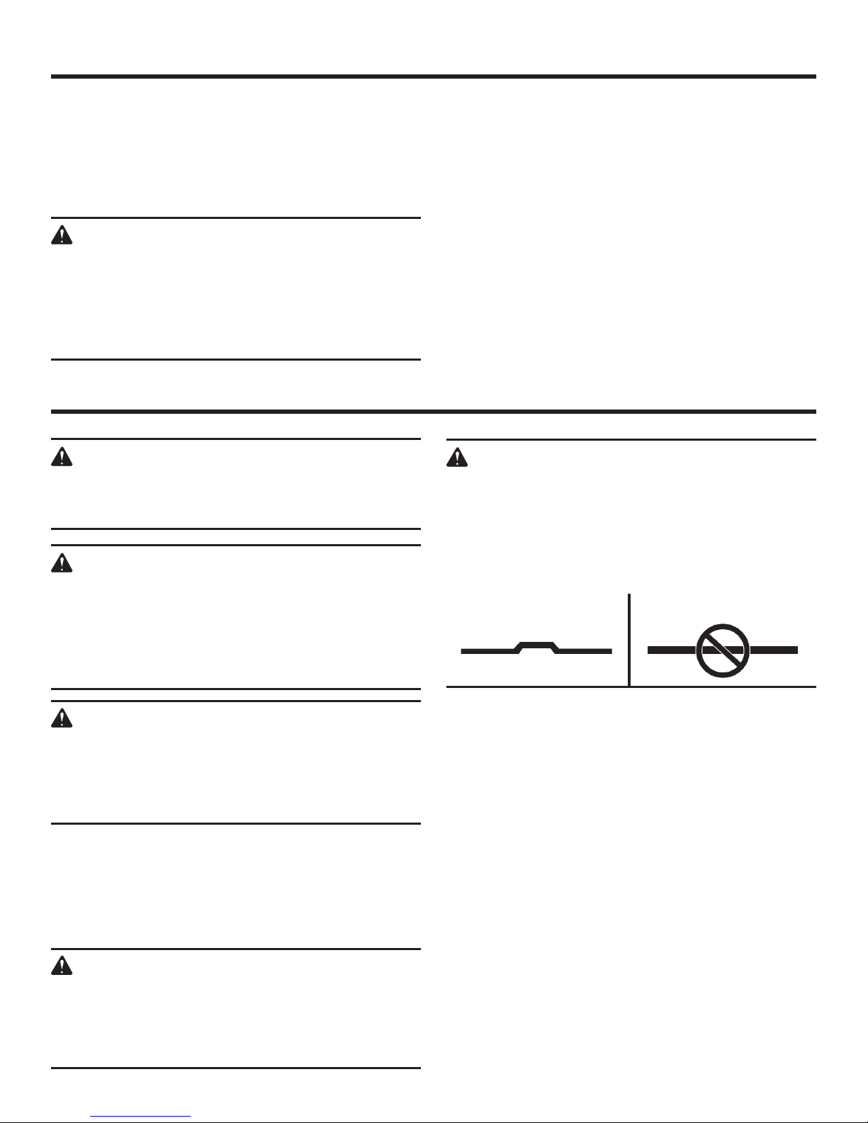
DANGER:
Use ONLY Type 27 depressed center grinding
wheels (such as the one provided with this
product). NEVER attach a Type 1 straight or cut-off
wheel to this angle grinder. Use of any other wheel
is not recommended and creates a hazard, which
will result in serious injury.
Type 27 − OK TO use Type 1 − dO nOT use
WARNING:
Do not use any attachments or accessories
not recommended by the manufacturer of this
product. The use of attachments or accessories
not recommended can result in serious personal
injury.
APPLICATIONS
You may use this product for the purposes listed below:
Grinding metals
Sanding wood or metal surfaces with an abrasive mop
disc. (sold separately)
DANGER:
Never attach a wood cutting or carving blade of
any type to this angle grinder. It is only designed for
grinding and sanding. Use for any other purpose
is not recommended and creates a hazard, which
will result in serious injury.
TURNING THE GRINDER ON/OFF
See Figure 7, page 16.
To turn the grinder ON:
Partially depress the lock-off / lock-on button and depress
the switch trigger.
To turn the grinder OFF:
Release the switch trigger.
LOCK-OFF / LOCK-ON BUTTON
See Figure 7, page 16.
This grinder is equipped with a lock-off / lock-on feature,
which is convenient for continuous grinding for extended
periods of time.
To lock-on:
Hold the grinder in front and away from you, keeping the
grinding wheel clear of the workpiece.
Partially depress the lock-off / lock-on button and depress
the switch trigger.
10 - English
Page 11

OPERATION
Depress and hold lock-off / lock-on button and release
the switch trigger.
Release the lock-off / lock-on button and the grinder will
continue running.
To release the lock, depress and release the switch
trigger.
NOTE: Ifthelock-off/lock-onfeatureisengagedandthe
grinder becomes disconnected from the power supply, disengage the lock-off / lock-on feature immediately.
WARNING:
To prevent loss of control and possible serious
injury, always operate the grinder with the side
handle installed.
OPERATING THE GRINDER
See Figure 8, page 16.
Always carefully select and use grinding wheels that are
recommended for the material to be ground. Make sure
that the operating speed of any accessory wheel selected is
rated at 10,000 r/min. or more. The grinding wheel provided
with the grinder is suitable for grinding welds, preparing
surfaces to be welded, grinding structural steel, and grinding stainless steel.
To operate the grinder:
Secure all work in a vise or clamp to a workbench.
DANGER:
Never use the grinder with the wheel guard
removed and always be sure the wheel guard is
locked into place. It has been designed for use
only with the wheel guard installed. Attempting to
use grinder with wheel guard removed will result in
loose particles being thrown against the operator
resulting in serious personal injury.
Hold the grinder in front and away from you with
both hands, keeping the grinding wheel clear of the
workpiece.
Turn on the grinder and let the motor and grinding wheel
build up to full speed.
Lower the grinder gradually until the grinding wheel con-
tacts the workpiece.
Keep the grinder tilted at an angle from 5 to 15 de-
grees.
WARNING:
To prevent loss of control and possible serious
personal injury, always operate the grinder
with both hands, keeping one hand on the side
handle.
Move the grinder continuously at a steady, consistent
pace.
CAUTION:
If the grinder is held in one spot too long, it will
gouge and cut grooves in the workpiece. If the
grinder is held at too sharp an angle, it will also
gouge the workpiece because of concentration of
pressure on a small area.
Use just enough pressure to keep the grinder from chat-
tering or bouncing.
NOTE: Heavy pressure will decrease the grinder’s speed and
put a strain on the motor. Normally the weight of the tool
alone is adequate for most grinding jobs. Use light pressure
when grinding jagged edges or loose bolts where there is the
potential for the grinder to snag on the metal edge.
Lift the grinder away from the workpiece before turning
off the grinder.
11 - English
Page 12

MAINTENANCE
WARNING:
When servicing use only identical RIDGID®
replacement parts. Use of any other parts may
create a hazard or cause product damage.
WARNING:
Always wear eye protection with side shields
marked to comply with ANSI Z87.1 along with
hearing protection and where necessary a full
face shield. Failure to do so could result in serious
personal injury. If operation is dusty, also wear a
dust mask.
GENERAL MAINTENANCE
Avoid using solvents when cleaning plastic parts. Most
plastics are susceptible to damage from various types of
commercial solvents and may be damaged by their use. Use
clean cloths to remove dirt, dust, oil, grease, etc.
WARNING:
Do not at any time let brake fluids, gasoline,
petroleum-based products, penetrating oils, etc.,
come in contact with plastic parts. Chemicals can
damage, weaken or destroy plastic which may
result in serious personal injury.
Electric tools used on fiberglass material, wallboard, spackling compounds, or plaster are subject to accelerated wear
and possible premature failure because the fiberglass chips
and grindings are highly abrasive to bearings, brushes,
commutators, etc. Consequently, we do not recommend
using this product for extended work on these types
of materials. However, if you do work with any of these
materials, it is extremely important to clean the product using compressed air.
LUBRICATION
All of the bearings in this product are lubricated with a sufficient amount of high grade lubricant for the life of the unit
under normal operating conditions. Therefore, no further
lubrication is required.
REPLACING THE WHEEL GUARD
After extended use, the wheel guard may wear and need
replacing. If you drop the grinder and damage the wheel
guard it may also be necessary for you to replace it. Refer
to Installing the Wheel Guard earlier in this manual.
BRUSH REPLACEMENT
See Figure 9, page 16.
This product has externally accessible brush assemblies
that should be periodically checked for wear.
Unplug the angle grinder.
With a flat head screwdriver, remove the brush caps. The
brush assembly is spring loaded and will pop out when
you remove the brush cap.
Remove the brush assembly (brush and spring). Check
for wear. Replace both brushes when either has less than
1/4 in. length of carbon remaining. Do not replace one
side without replacing the other.
Reassemble using new brush assemblies. Make sure
curvature of brush matches curvature of motor and that
brush moves freely in brush tube.
Replace brush cap and tighten securely. Do not over-
tighten.
NOTE: FIGURES (ILLUSTRATIONS) START ON PAGE 14
AFTER FRENCH AND SPANISH LANGUAGE SECTIONS
12 - English
Page 13

WARRANTY
RIDGID® HAND HELD AND STATIONARY POWER TOOL
3 YEAR LIMITED SERVICE WARRANTY
Proof of purchase must be presented when requesting
warranty service.
Limited to RIDGID® hand held and stationary power tools
purchased 2/1/04 and after. This product is manufactured
by One World Technologies, Inc. The trademark is licensed
from RIDGID, Inc. All warranty communications should be
directed to One World Technologies, Inc., attn: RIDGID Hand
Held and Stationary Power Tool Technical Service at (toll
free) 1-866-539-1710.
90-DAY SATISFACTION GUARANTEE POLICY
During the first 90 days after the date of purchase, if you are
dissatisfied with the performance of this RIDGID® Hand Held
and Stationary Power Tool for any reason you may return
the tool to the dealer from which it was purchased for a full
refund or exchange. To receive a replacement tool you must
present proof of purchase and return all original equipment
packaged with the original product. The replacement tool
will be covered by the limited warranty for the balance of
the 3 YEAR service warranty period.
WHAT IS COVERED UNDER THE 3 YEAR
LIMITED SERVICE WARRANTY
This warranty on RIDGID® Hand Held and Stationary Power
Tools covers all defects in workmanship or materials and
normal wear items such as brushes, chucks, motors, switches, cords, gears and even cordless batteries in this RIDGID®
tool for three years following the purchase date of the tool.
Warranties for other RIDGID® products may vary.
HOW TO OBTAIN SERVICE
To obtain service for this RIDGID® tool you must return it;
freight prepaid, or take it in to an authorized service center
for RIDGID® branded hand held and stationary power tools.
You may obtain the location of the authorized service center nearest you by calling (toll free) 1-866-539-1710 or by
logging on to the RIDGID® website at www.ridgid.com.
When requesting warranty service, you must present the
original dated sales receipt. The authorized service center will
repair any faulty workmanship, and either repair or replace
any part covered under the warranty, at our option, at no
charge to you.
WHAT IS NOT COVERED
This warranty applies only to the original purchaser at
retail and may not be transferred. This warranty only covers
defects arising under normal usage and does not cover any
malfunction, failure or defect resulting from misuse, abuse,
neglect, alteration, modification or repair by other than
an authorized service center for RIDGID® branded hand
held and stationary power tools. Consumable accessories
provided with the tool such as, but not limited to, blades,
bits and sand paper are not covered.
RIDGID, INC. AND ONE WORLD TECHNOLOGIES, INC.
MAKE NO WARRANTIES, REPRESENTATIONS OR
PROMISES AS TO THE QUALITY OR PERFORMANCE
OF ITS POWER TOOLS OTHER THAN THOSE SPECIFICALLY STATED IN THIS WARRANTY.
ADDITIONAL LIMITATIONS
To the extent permitted by applicable law, all implied
warranties, including warranties of MERCHANTABILITY or
FITNESS FOR A PARTICULAR PURPOSE, are disclaimed.
Any implied warranties, including warranties of merchantability or fitness for a particular purpose, that cannot be
disclaimed under state law are limited to three years from the
date of purchase. One World Technologies, Inc. and RIDGID,
Inc. are not responsible for direct, indirect, incidental or
consequential damages. Some states do not allow
limitations on how long an implied warranty lasts and/or
do not allow the exclusion or limitation of incidental or
consequential damages, so the above limitations may not
apply to you. This warranty gives you specific legal rights,
and you may also have other rights which vary from state
to state.
One World Technologies, Inc.
P.O. Box 35, Hwy. 8
Pickens, SC 29671
13 - English
Page 14

RÈGLES DE SÉCURITÉ GÉNÉRALES
AVERTISSEMENT :
Lire toutes les instructions. Le non-respect de
toutes les instructions ci-dessous peut entraîner un
choc électrique, un incendie et / ou des blessures
graves.
CONSERVER CES INSTRUCTIONS
LIEU DE TRAVAIL
Garder le lieu de travail propre et bien éclairé. Les établis
encombrés et les endroits sombres sont propices aux
accidents.
Ne pas utiliser d’outils électriques dans des atmosphères
explosives, par exemple en présence de liquides, gaz ou
poussières inflammables. Les outils électriques produisent
des étincelles risquant d’enflammer les poussières ou
vapeurs.
Garder les badauds, enfants et visiteurs à l’écart pendant
l’utilisation d’un outil électrique. Les distractions peuvent
causer une perte de contrôle.
SÉCURITÉ ÉLECTRIQUE
Les outils à double isolation sont équipés d’une fiche
polarisée (une broche est plus large que l’autre). Cette
fiche ne peut être branchée sur une prise polarisée
que dans un sens. Si la fiche ne peut pas être insérée
dans la prise, l’inverser. Si elle ne peut toujours pas
être insérée, faire installer une prise polarisée par un
électricien qualifié. Ne pas modifier la fiche, de quelque
façon que ce soit. La double isolation
de cordon d’alimentation à trois fils et d’un circuit secteur
mis à la terre.
Éviter tout contact du corps avec des surfaces mises
à la terre,
réfrigérateurs. Le risque de choc électrique est accru lorsque
le corps est mis à la terre.
Ne pas exposer les outils électriques à la pluie ou
l’humidité. La pénétration d’eau dans ces outils accroît le
risque de choc électrique.
Ne pas maltraiter le cordon d’alimentation. Ne jamais
utiliser le cordon d’alimentation pour transporter l’outil et
ne jamais débrancher ce dernier en tirant sur le cordon.
Garder le cordon à l’écart de la chaleur, de l’huile,
des objets tranchants et des pièces en mouvement.
Remplacer immédiatement tout cordon endommagé. Un
cordon endommagé accroît le risque de choc électrique.
Pour les travaux à l’extérieur, utiliser un cordon spécialement
conçu à cet effet, marqué « W-A » ou « W ». Ces cordons
réduisent les risques de choc électrique.
SÉCURITÉ PERSONNELLE
Rester attentif, prêter attention au travail et faire preuve
de bon sens lors de l’utilisation de tout outil électrique.
Ne pas utiliser cet outil en état de fatigue ou sous
l’influence d’alcool, de drogues ou de médicaments.
Un moment d’inattention pendant l’utilisation d’un outil
électrique peut entraîner des blessures graves.
Porter une tenue appropriée. Ne porter ni vêtements
amples, ni bijoux. Attacher ou couvrir les cheveux longs.
telles que tuyaux, radiateurs, cuisinières et
élimine le besoin
Retirer les outils et clés de réglage avant de mettre l’outil
Ne pas travailler hors de portée. Toujours se tenir bien
Utiliser l’équipement de sécurité. Toujours porter une
Ne porter ni vêtements amples, ni bijoux. Attacher
Ne pas utiliser l’outil sur une échelle ou un support
UTILISATION ET ENTRETIEN DE L’OUTIL
Utiliser des serre-joints ou un autre système approprié
Ne pas forcer l’outil. Utiliser un outil approprié pour
Ne pas utiliser l’outil si le commutateur ne permet pas
Débrancher l’outil davant d’effectuer des réglages, de
Ranger les outils non utilisés hors de portée des enfants
Entretenir soigneusement les outils. Garder les outils
Vérifier qu’aucune pièce mobile n’est mal alignée,
3 - Français
Garder les cheveux, les vêtements et les gants à l’écart
des pièces en mouvement. Les vêtements amples, bijoux
et cheveux longs peuvent se prendre dans les pièces en
mouvement.
Éviter les démarrages accidentels. S’assurer que le
commutateur est en position d’arrêt avant de brancher
l’outil. Porter un outil avec le doigt sur son commutateur ou
brancher un outil dont le commutateur est en position de
marche de marche peut causer un accident.
en marche. Un outil ou une clé laissée sur une pièce rotative
de l’outil peut causer des blessures.
campé et en équilibre. Une bonne tenue et un bon équilibre
permettent de mieux contrôler l’outil en cas de situation
imprévue.
protection oculaire. Suivant les conditions, le port d’un
masque antipoussière, de chaussures de sécurité, d’un
casque ou d’une protection auditive est recommandé.
ou couvrir les cheveux longs. Les vêtements amples,
bijoux et cheveux longs peuvent se prendre dans les ouïes
d’aération.
instable. Une bonne tenue et un bon équilibre permettent
de mieux contrôler l’outil en cas de situation imprévue.
pour maintenir fermement la pièce sur une surface
stable. Une pièce tenue à la main ou contre son corps est
instable et peut causer une perte de contrôle.
le travail. Un outil approprié exécutera le travail mieux et
de façon moins dangereuse s’il est utilisé dans les limites
prévues.
de le mettre en marche et de l’arrêter. Tout outil qui ne
peut pas être contrôlé par son commutateur est dangereux
et doit être réparé.
changer d’accessoire ou de ranger l’outil. Ces mesures
de sécurité réduisent les risques de démarrage accidentel
de l’outil.
et des personnes n’ayant pas reçu des instructions
adéquates. Dans les mains de personnes n’ayant pas reçu
des instructions adéquates, les outils sont dangereux.
bien affûtés et propres. Des outils correctement entretenus
et dont les tranchants sont bien affûtés risquent moins de
se bloquer et sont plus faciles à contrôler.
grippée ou brisée et s’assurer qu’aucun autre problème
risque d’affecter le bon fonctionnement de l’outil. En cas
de dommages, faire réparer l’outil avant de l’utiliser de
nouveau. Beaucoup d’accidents sont causés par des outils
mal entretenus.
Page 15

RÈGLES DE SÉCURITÉ GÉNÉRALES
Utiliser exclusivement les accessoires recommandés par le
fabricant pour le modèle d’outil. Des accessoires appropriés pour
un outil peuvent être dangereux s’ils sont utilisés avec un autre.
Garder l’outil et sa poignée secs, propres et exempts d’huile ou
de graisse. Toujours utiliser un chiffon propre pour le nettoyage.
Ne jamais utiliser de liquide de freins, d’essence, de produits
à base de pétrole ou de solvants forts pour nettoyer l’outil. Le
respect de cette consigne réduira les risques de perte de contrôle
et d’endommagement du boîtier en plastique.
RÈGLES DE SÉCURITÉ PARTICULIÈRES
Cet outil électrique est conçu pour servir de meuleuse, de
ponceuse, de brosse métallique ou de polisseuse. Consulter
tous les avertissements et toutes les instructions, les
illustrations et les précisions fournis avec cet outil électrique.
Ne pas suivre l’ensemble des instructions décrites ci-dessous peut
entraîner une électrocution, un incendie ou des blessures graves.
Il n’est pas recommandé d’utiliser cet outil électrique pour
couper des pièces. Le fait d’utiliser l’outil pour effectuer des
tâches pour lesquelles il n’est pas conçu peut présenter du danger
et entraîner des blessures.
Ne pas utiliser des accessoires qui ne sont pas spécialement
conçus pour le modèle d’outil ou qui ne sont pas recommandés
par le fabricant. Le simple fait qu’un accessoire peut s’ajuster
sur l’outil électrique ne signifie pas qu’il peut être utilisé en toute
sécurité.
La vitesse nominale de l’accessoire doit au moins être égale à la
vitesse maximale indiquée sur l’outil électrique. Les accessoires
qui sont utilisés à une vitesse supérieure à leur VITESSE NOMINALE
peuvent se briser et se détacher.
Le diamètre extérieur et l’épaisseur de l’accessoire doivent être
conformes à la capacité de l’outil électrique. Il est impossible
d’envelopper ou de contrôler adéquatement un accessoire de
dimension inappropriée.
La taille de l’arbre des meules, des brides, des plateaux porte-
disque ou de tout autre accessoire doit convenir parfaitement à
la broche de l’outil électrique. Si les accessoires utilisés sont dotés
d’alésages centraux qui ne conviennent pas à la pièce de montage
de l’outil, ils se déstabiliseront, vibreront de façon excessive et
pourront causer une perte de contrôle.
Ne pas utiliser un accessoire endommagé. Inspecter
l’accessoire avant chaque utilisation afin de s’assurer que
les meules, par exemple, sont exemptes d’ébréchures et de
fissures, que le plateau porte-disque est exempt de fissures
et qu’il n’est pas usé de façon excessive, et que la brosse
métallique ne comprend pas de fils détachés ou craquelés.
Si l’outil électrique ou l’accessoire est échappé, s’assurer
qu’il n’est pas endommagé ou installer un autre accessoire.
Après avoir effectué cette opération, se tenir à distance de
l’accessoire en rotation et faire fonctionner l’outil à sa vitesse
à vide maximale pendant une minute. S’assurer que personne
ne se tient à proximité de l’outil. Les accessoires endommagés se
brisent généralement lors de cette vérification.
Porter de l’équipement de protection de qualité professionnelle.
Selon le type d’opération, porter un masque de protection
ou des lunettes de sécurité. Au besoin, porter également un
masque antipoussières, un protecteur d’oreille, des gants et
un tablier d’atelier résistant aux petits fragments abrasifs ou
aux fragments provenant des pièces à travailler. La protection
oculaire utilisée doit résister aux débris projetés lors des
différentes opérations. La protection oculaire utilisée doit résister
aux débris projetés lors des différentes opérations. Le masque
anti-poussières et le masque filtrant doivent filtrer les particules
DÉPANNAGE
Le dépannage des outils doit être confié exclusivement à un
personnel qualifié. Les réparations ou entretiens effectués par des
personnes non qualifiées présentent des risques de blessures.
Utiliser exclusivement des pièces identiques à celles d’origine
pour les réparations. Se conformer aux instructions de la
section Entretien de ce manuel. L’usage de pièces non autorisées
ou le non-respect des instructions peut présenter des risques de
choc électrique ou de blessures.
produites lors de l’opération. Une exposition prolongée à un bruit
fort peut entraîner une perte auditive.
S’assurer que personne ne se tient à proximité du lieu de
travail. Toute personne qui entre sur le lieu de travail doit porter
l’équipement de protection requis. Des fragments provenant de
la pièce à travailler ou d’un accessoire brisé peuvent être projetés
et causer des blessures, même à des personnes se tenant à une
certaine distance du lieu de travail immédiat.
Tenir l’outil par ses surfaces de préhension isolées lors des
opérations pendant lesquelles l’accessoire de coupe peut
entrer en contact avec du câblage caché ou avec son propre
cordon d’alimentation. Le contact d’un accessoire de coupe avec
un fil sous tension « électrifie » les pièces métalliques exposées de
l’outil et peut électrocuter l’utilisateur.
Tenir le cordon loin de l’accessoire en rotation. En cas de perte
de contrôle, le cordon peut être coupé ou accroché, et la main ou
le bras de l’utilisateur risquent d’entrer en contact avec l’accessoire
en rotation.
Ne jamais déposer l’outil électrique avant l’arrêt complet de
l’accessoire. L’accessoire en rotation peut attraper la surface et
occasionner une perte de contrôle.
Ne jamais laisser l’outil électrique fonctionner en le transportant
à ses côtés. L’acc essoire en rotation peut s’acc rocher
accidentellement aux vêtements et entrer en contact avec
l’utilisateur.
Nettoyer régulièrement les évents d’aération de l’outil
électrique. Le ventilateur du moteur aspire la poussière dans le
logement et crée une accumulation excessive de métal fritté, ce
qui peut causer un danger électrique.
Ne pas faire fonctionner l’outil électrique à proximité de
matériaux inflammables. Les étincelles peuvent enflammer ces
matériaux.
Ne pas utiliser d’accessoires qui nécessitent des liquide
de refroidissement. L’utilisation d’eau ou d’un autre liquide
de refroidissement peut entraîner une électrocution ou un choc
électrique.
Tenir fermement l’outil électrique et placer le corps et les mains
de manière à pouvoir résister aux rebonds. Toujours utiliser
la poignée auxiliaire, s’il y en a une, pour assurer un contrôle
optimal en cas de rebond ou de réaction de couple lors du
démarrage de l’outil. L’utilisateur peut contrôler les rebonds et
les réactions de couple s’il respecte les directives prescrites.
Ne jamais placer les mains à proximité de l’accessoire en
rotation. En cas de rebond, l’accessoire peut dévier sur celles-ci.
Ne pas positionner le corps à l’endroit où sera entraîné l’outil
électrique si un rebond se produit. Un rebond entraînera l’outil
dans le sens opposé au mouvement de la meule, à l’endroit de
l’accrochage.
Faire preuve d’une extrême prudence au moment d’utiliser
l’outil sur des coins ou des rebords tranchants. Les coins, les
rebords tranchants et les surfaces qui tressautent ont tendance à
4 - Français
Page 16

RÈGLES DE SÉCURITÉ PARTICULIÈRES
s’accrocher à la pièce en rotation et à causer une perte de contrôle
ou des rebonds.
Ne pas fixer une lame de sculpteur pour scie à chaîne ou une
lame de scie dentée. Ces deux types de lame occasionnent de
nombreux rebonds et des pertes de contrôle fréquentes.
Utiliser seulement les types de meule recommandés pour cet
outil électrique et le garde-meule spécialement conçu pour la
meule utilisée. Il est impossible d’envelopper de façon adéquate
et sécuritaire les meules qui ne sont pas spécialement conçues
pour l’outil électrique.
Le garde-meule doit être fixé solidement à l’outil électrique
et positionné de manière à garantir une sécurité optimale;
il importe donc de diriger le moins possible la meule vers
l’utilisateur. Le garde meule aide à protéger l’utilisateur des
fragments qui peuvent se détacher de la meule et du contact
accidentel avec la meule.
Utiliser seulement les meules pour effectuer des opérations
pour lesquelles elles sont conçues. Par exemple, ne pas meuler
avec le côté d’une meule à tronçonner. Seule la périphérie des
meules à tronçonner abrasives doit être utilisée pour le meulage.
Le fait d’appliquer une force latérale sur ces meules peut provoquer
leur éclatement.
Toujours utiliser des brides de meule non endommagées de
formes et de dimensions convenables pour la meule choisie. Les
brides de meule adéquates soutiennent la meule, ce qui minimise
les risques de bris de celle-ci. Les brides de meules à tronçonner
peuvent différer des brides de meules standards.
Ne pas utiliser de meules usées qui proviennent d’outils
électriques de plus grandes dimensions. Les meules conçues
pour des outils électriques de plus grandes dimensions ne
conviennent pas à la vitesse plus élevée des outils de plus petites
dimension et peuvent éclater.
Ne pas utiliser un papier pour disque abrasif surdimensionné.
Suivre les recommandations du fabricant au moment de choisir
le papier abrasif. Un papier abrasif qui excède la surface du disque
de ponçage présente un danger de lacération et peut s’accrocher,
se déchirer, ou entraîner un rebond.
Ne permettre à aucune partie lâche de la coiffe à polir ou à
ses filaments de tourner librement. Enlever ou couper tous
les filaments libres. Les filaments libres et en rotation peuvent
s’empêtrer dans les doigts ou s’accrocher à la pièce à travailler.
Porter une attention particulière à la brosse métallique, dont
les poils peuvent être projetés même pendant une opération
régulière. Éviter de surcharger les poils en appuyant sur la
brosse de manière excessive. Les poils de la brosse métallique
peuvent pénétrer facilement dans les vêtements légers ou la
peau.
S’il est recommandé d’installer un dispositif protecteur pour
utiliser une brosse métallique, s’assurer qu’il n’entre pas en
contact avec la brosse. Le diamètre de la brosse métallique peut
augmenter en raison de la charge et de la force centrifuge.
Toujours utiliser le garant correct avec la meule. Un garant
protège l’opérateur des fragments de roue cassés.
Apprendre à connaître l’outil. Lire attentivement le manuel
d’utilisation. Apprendre les applications et les limites de l’outil,
ainsi que les risques spécifiques relatifs à son utilisation. Le
respect de cette consigne réduira les risques d’incendie, de choc
électrique et de blessures graves.
Toujours porter une protection oculaire avec écrans latéraux
certifiée conforme à la norme ANSI Z87.1. Le non respect de
cette règle peut faire en sorte que des liquides soient projetés dans
vos yeux, ce qui peut entraîner des blessures graves.
Protection respiratoire. Porter un masque facial ou un masque
anti-poussière si le travail produit de la poussière. Le respect
de cette consigne réduira les risques de blessures graves.
Protection auditive. Porter une protección auditiva lors de
l’utilisation prolongée. Le respect de cette règle réduira les risques
de blessures graves.
Inspecter régulièrement les cordons d’alimentation des outils
et s’ils sont endommagés, les confier au centre de réparations
agréé le plus proche. Toujours être conscient de l’emplacement
du cordon. Le respect de cette règle réduira les risques de choc
électrique et d’incendie.
Vérifier l’état des pièces. Avant d’utiliser l’outil de nouveau
examiner soigneusement les pièces et dispositifs de protection
qui semblent endommagés afin de déterminer s’ils fonctionnent
correctement et s’ils remplissent les fonctions prévues. Vérifier
l’alignement des pièces mobiles, s’assurer qu’aucune pièce
n’est bloquée ou cassée, vérifier la fixation de chaque pièce
et s’assurer qu’aucun autre problème ne risque d’affecter
le bon fonctionnement de l’outil. Toute protection ou pièce
endommagée doit être correctement réparée ou remplacée
dans un centre de réparations agréé. Le respect de cette
consigne réduira les risques de choc électrique, d’incendie et de
blessures graves.
S’assurer que le cordon prolongateur est en bon état. Si un
cordon prolongateur est utilisé, s’assurer que sa capacité
est suffisante pour supporter le courant de fonctionnement
de l’outil. Un calibre de fil (A.W.G) d’au minimum 14 est
recommandé pour un cordon prolongateur de 8 m (25 pi)
ou moins. L’usage d’un cordon de plus de 15 m (50 pi) est
déconseillé. En cas de doute, utiliser un cordon du calibre
immédiatement supérieur. Moins le numéro de calibre est
élevé, plus la capacité du fil est grande. Un cordon de capacité
insuffisante causerait une baisse de la tension de ligne, entraînant
une perte de puissance et une surchauffe.
Inspecter la pièce et retirer les clous éventuels avant d’utiliser
cet outil. Le respect de cette consigne réduira les risques de
blessures graves.
Si le cordon d’alimentation est endommagé, il doit être remplacé
uniquement pas le fabricant ou par un centre de réparation agréé
pour éviter tout risque.
Conserver ces instructions. Les consulter fréquemment et les
utiliser pour instruire les autres utilisateurs éventuels. Si cet outil
est prêté, il doit être accompagné de ces instructions.
AVERTISSEMENT :
La poussière dégagée par certains matériaux lors du ponçage, sciage, meulage perçage et autres opérations de construction
contient des produits chimiques reconnus causer le cancer, des malformations congénitales ou des lésions de l’appareil
reproducteur. Voici certains exemples de ces produits chimiques :
•plombcontenudanslapeintureauplomb,
•silicecristallinecontenuedanslesbriques,lecimentetd’autresproduitsdemaçonnerie,ainsique
•arsenicetchromecontenusdansleboisdeconstructiontraitéparproduitschimiques.
Le risque présenté par l’exposition à ces produits varie en fonction de la fréquence de ce type de travail. Pour réduire l’exposition
à ces produits chimiques : travailler dans un endroit bien aéré et utiliser des équipements de sécurité approuvés tels que
masques antipoussière spécialement conçus pour filtrer les particules microscopiques.
5 - Français
Page 17

SYMBOLES
Les termes de mise en garde suivants et leur signification ont pour but d’expliquer le degré de risques associé à
l’utilisation de ce produit.
SYMBOLE SIGNAL SIGNIFICATION
DANGER :
AVERTISSEMENT :
ATTENTION :
ATTENTION :
Certains des symboles ci-dessous peuvent être utilisés sur produit. Veiller à les étudier et à apprendre leur signification.
Une interprétation correcte de ces symboles permettra d’utiliser produit plus efficacement et de réduire les risques.
Indique une situation extrêmement dangereuse qui, si elle n’est pas
évitée, aura pour conséquences des blessures graves ou mortelles.
Indique une situation potentiellement dangereuse qui, si elle n’est pas
évitée, pourrait entraîner des blessures graves ou mortelles.
Indique une situation potentiellement dangereuse qui, si elle n’est
pas évitée, pourraît entraîner des blessures légères ou de gravité
modérée.
(Sans symbole d’alerte de sécurité) Indique une situation pouvant
entraîner des dommages matériels.
SYMBOLE NOM DÉSIGNATION / EXPLICATION
Symbole d’alerte de sécurité Indique un risque de blessure potentiel.
Pour réduire les risques de blessures, l’utilisateur doit lire et
Lire le manuel d’utilisation
veiller à bien comprendre le manuel d’utilisation avant d’utiliser
ce produit.
Protection oculaire et auditive
Porter des gants Toujours porter des gants au moment d’utiliser le produit.
Avertissement concernant
l’humidité
V Volts Tension
A Ampères Intensité
Hz Hertz Fréquence (cycles par seconde)
W Watts Puissance
min Minutes Temps
Courant alternatif Type de courant
n
o
Vitesse à vide Vitesse de rotation à vide
Construction de classe II Construction à double isolation
Toujours porter une protection oculaire certifiée conforme à la norme
ANSI Z87.1 ainsi qu’un protection auditive.
Ne pas exposer à la pluie ou l’humidité.
.../min Par minute Tours, coups, vitesse périphérique, orbites, etc., par minute
6 - Français
Page 18

CARACTÉRISTIQUES ÉLECTRIQUES
DOUBLE ISOLATION
La double isolation est un dispositif de sécurité utilisé sur les
outils à moteur électriques, éliminant le besoin de cordon
d’alimentation habituel à trois fils avec terre. Toutes les
pièces métalliques exposées sont isolées des composants
internes du moteur par l’isolation protectrice. Les outils à
double isolation ne nécessitent pas de mise à la terre.
AVERTISSEMENT :
Le système à double isolation est conçu pour
protéger l’utilisateur contre les chocs électriques
causés par une rupture du câblage interne de
l’outil. Prendre toutes les précautions de sécurité
normales pour éviter les chocs électriques.
NOTE : La réparation d’un outil à double isolation exige
des précautions extrêmes ainsi que la connaissance du
système, elle ne doit être confiée qu’à un réparateur qualifié.
En ce qui concerne les réparations, nous recommandons de
confier l’outil au centre de réparations le plus proche. Utiliser
exclusivement des pièces d’origine pour les réparations.
CONNEXIONS ÉLECTRIQUES
Ce produit est équipé d’un moteur électrique de précision.
Il doit être branché uniquement sur une alimentation 120 V,
c.a. (courant résidentiel standard), 60 Hz. Ne pas utiliser
cet outil sur une source de courant continu (c.c.). Une chute
de tension importante causerait une perte de puissance et
une surchauffe du moteur. Si l’outil ne fonctionne pas une
fois branché, vérifier l’alimentation électrique.
CORDONS PROLONGATEURS
Lors de l’utilisation d’un outil électrique à grande distance
d’une prise secteur, veiller à utiliser un cordon prolongateur
d’une capacité suffisante pour supporter l’appel de courant
de l’outil. Un cordon de capacité insuffisante causerait
une baisse de la tension de ligne, entraînant une perte
de puissance et une surchauffe. Se reporter au tableau
ci-dessous pour déterminer le calibre minimum de fil requis
pour un cordon donné. Utiliser exclusivement des cordons à
gaine cylindrique homologués par Underwriter’s Laboratories
(UL).
Pour le travail à l’extérieur, utiliser un cordon prolongateur
spécialement conçu à cet effet. Ce type de cordon porte
l’inscription « WA » ou « W » sur sa gaine.
Avant d’utiliser un cordon prolongateur, vérifier que ses fils
ne sont ni détachés ni exposés et que son isolation n’est ni
coupée, ni usée.
**Intensité nominale (sur la plaquette signalétique de l’outil)
0-2,0 2,1-3,4 3,5-5,0 5,1-7,0 7,1-12,0 12,1-16,0
Longueur du cordon Calibre de fil (A.W.G.)
25´ 16 16 16 16 14 14
50´ 16 16 16 14 14 12
100´ 16 16 14 12 10 —
**Utilisé sur circuit de calibre 12 – 20 A
NOTE : AWG = American Wire Gauge
AVERTISSEMENT :
Maintenir le cordon prolongateur à l’écart de la
zone de travail. Lors du travail avec un cordon
électrique, placer le cordon de manière à ce qu’il ne
risque pas de se prendre dans les pièces de bois,
outils et autres obstacles. Ne pas prendre cette
précaution peut entraîner des blessures graves.
AVERTISSEMENT :
Vérifier l’état des cordons prolongateurs avant
chaque utilisation. Remplacer immédiatement tout
cordon endommagé. Ne jamais utiliser un outil
dont le cordon d’alimentation est endommagé,
car tout contact avec la partie endommagée
pourrait causer un choc électrique et des blessures
graves.
7 - Français
Page 19

CARACTÉRISTIQUES
FICHE TECHNIQUE
Taille de meule .........................................115 mm (4,5 po)
Diamètre de broche ....................... 5/8 po x 11 UNC (M14)
Vitesse à vide ......................................10 000 r/min. (RPM)
Entrée ....................120 volts, c.a. uniquement, 60 Hz, 7 A
Poids net ...................................................... 2,1 kg (4.7 lb)
VEILLER À BIEN CONNAÎTRE LA MEULEUSE
D’ANGLE
Voir la figure 1, page 14.
L’utilisation sûre de ce produit exige une comprehension
des renseignements figurant sur l’outil et contenus dans le
manuel d’utilisation, ainsi qu’une bonne connaissance du
projet entrepris. Avant d’utiliser ce produit, se familiariser
avec toutes ses caractéristiques et règles de sécurité.
BALAIS ACCESSIBLES DE L’EXTÉRIEUR
Balais accessibles de l’extérieur pour une longévité accrue
de la meuleuse.
FICHE LUMINEUSE
Cette meuleuse est équipée d’une fiche qui s’illumine lorsque
l’outil est sous tension. La fiche lumineuse permet d’identifier
rapidement les outils sous tension.
BOU T ON D E VER R OUI L LAG E ET D E
DÉVERROUILLAGE
Le bouton de verrouillage et de déverrouillage permet de
réduire le risque d’un démarrage accidentel et est pratique
pour un meulage continu pendant une période prolongée.
BOUTON DE VERROUILLAGE DE L’AXE
Ce bouton bloque l’axe, ce qui permet de remplacer la meule
avec une seule clé.
POIGNÉE LATÉRALE À TROIS POSITIONS
La poignée latérale est conçue pour stabiliser la meuleuse
et elle doit être utilisée en toutes circonstances. Outre le
maintien du contrôle pendant l’utilisation, la poignée facilite
le travail.
GARDE-MEULE
Le garde-meule est réglable en 6 positions afin d’assurer
une protection contre les étincelles et les éclats de métal
pendant l’utilisation.
ASSEMBLAGE
DÉBALLAGE
Ce produit nécessite l’assemblage.
Avec précaution, sortir le produit et les accessoires de la
boîte. S’assurer que toutes les pièces figurant sur la liste
de contrôle sont incluses.
AVERTISSEMENT :
Ne pas utiliser le produit si, en le déballant, vous
constatez que des éléments figurant dans la liste
de contrôle d’expédition sont déjà assemblés.
Certaines pièces figurant sur cette liste n’ont pas
été assemblées par le fabricant et exigent une
installation. Le fait d’utiliser un produit qui a été
assemblé de façon inadéquate peut entraîner des
blessures.
Examiner soigneusement le produit pour s’assurer
que rien n’a été brisé ou endommagé en cours de
transport.
Ne pas jeter les matériaux d’emballage avant d’avoir
soigneusement examiné le produit et avoir vérifié qu’il
fonctionne correctement.
Si des pièces sont manquantes ou endommagées,
appeler le 1-866-539-1710.
LISTE DE CONTRÔLE D’EXPÉDTION
Meuleuse d’angle
Garde-meule
Écrou à épaulement
Bride circulaire
Meule
Poignée latérale
Clé
Sacoche à outils
Manuel d’utilisation
8 - Français
Page 20

ASSEMBLAGE
AVERTISSEMENT :
Si des pièces manquent ou sont endommagées,
ne pas utiliser ce produit avant qu’elles aient été
remplacées. Le fait d’utiliser ce produit même
s’il contient des pièces endommagées ou s’il lui
manque des pièces peut entraîner des blessures
graves.
AVERTISSEMENT :
Ne pas essayer de modifier cet outil ou de créer des
accessoires non recommandés pour ce produit. De
telles altérations ou modifications sont considérées
comme un usage abusif et peuvent créer des
conditions dangereuses, risquant d’entraîner des
blessures graves.
AVERTISSEMENT :
Ne pas brancher sur le secteur avant d’avoir terminé
l’assemblage. Le non-respect de cet avertissement
peut causer un démarrage accidentel, entraînant
des blessures graves.
INSTALLATION DE LE GARDE-MEULE
Voir la figure 2, page 14.
Placer le garde-meule neuf sur l’épaulement du chapeau
de roulement en alignant les flèches du garde-meule et
du chapeau de roulement. Appuyer sur le dispositif de
protection jusqu’à ce qu’il soit bien en place.
Appuyer sur le levier et tourner le garde-meule jusqu’à
ce qu’il se verrouille à l’une des six positions possibles.
Consulter la section intitulée Positionnement du garde-
meule.
NOTE : S’assurer que les trois onglets du garde-meule
sont appuyés dans les trois rainures du couvercle de
palier.
Remonter la bride circulaire, de la meule et de l’écrou à
épaulement. Voir la section Installation de la meule.
Serrer fermement l’écrou à épaulement à l’aide de la
clé fournie.
INSTALLATION/REMPLACEMENT DE LA MEULE
Voir la figure 2, page 14.
AVERTISSEMENT :
Inspecter soigneusement les meules neuves avant
de les installer.
• Frappe r lé gèrem ent le po urtour d e la
meule avec un maillet en bois.
• Écouterattentivementle sonproduit. Leson
change lorsque la meule est frappée à en
endroit fissuré ou fendu.
Ne pas utiliser les meules présentant des fissures
ou fêlures.
Après avoir installé une meule neuve la tester en la
laissant tourne à vide pendant environ une minute,
en veillant à ne pas la diriger vers des personnes
ou objets.
Débrancher la meuleuse.
Appuyer sur le bouton de verrouillage de l’axe et
tourner l’écrou à épaulement jusqu’à ce que l’axe se
verrouille.
NOTE : Pour éviter des dommages à l’axe et à son
verrouillage, toujours laisser le moteur s’arrêter
complètement avant d’engager le verrouillage.
Desserrer et retirer ll’écrou à épaulement de l’axe. Ne
pas retirer le bride circulaire.
S’assure que les méplats au dessous de la bride
circulaire s’engagent dans ceux de l’axe.
Placer la meule sur l’axe.
AVERTISSEMENT :
Toujours installer les meules côté concave contre
la bride circulaire. Si cette précaution n’est pas
prise, la meule se brisera lors du serrage de l’écrou.
Ceci pourrait entraîner des blessures graves par les
morceaux de meule projetés. Ne pas trop serrer.
Visser l’écrou à épaulement sur l’axe, son côté plat étant
dirigé vers le haut.
Engager la partie saillante de petit diamètre de l’écrou
à épaulementdans le trou de la meule et serrer à la
main.
Appuyer sur le bouton de verrouillage de l’axe et tourner
la meule dans le sens horaire jusqu’à ce que l’axe se
verrouille en position.
Serrer fermement l’écrou à épaulement à l’aide de la clé
fournie. Ne pas trop serrer.
DANGER :
Ne jamais attacher une meule de tronçonnage ni
une meule de TYPE 1 à cette meuleuse angulaire.
Elle est exclusivement conçue pour le meulage.
Tout autre usage est déconseillé et présente un
risque de blessures graves.
9 - Français
Page 21

ASSEMBLAGE
INSTALLATION DE LA POIGNÉE LATÉRALE
Voir la figure 3, page 15.
Débrancher la meuleuse.
Visser la poignée latérale dans le carter d’engrenage.
NOTE : La poignée peut être montée à droite ou
à gauche ou sur le dessus, selon la préférence de
l’utilisateur. Elle doit toujours être utilisée pour éviter
une perte de contrôle pouvant entraîner des blessures
graves.
Serrer la poignée latérale fermement.
POSITIONNEMENT DU GARDE-MEULE
Voir les figures 4 á 6, page 15.
Le garde-meule de la meuleuse doit être installé correctement,
selon l’endroit où est montée la poignée latérale. Ne jamais
utiliser la meuleuse si le garde-meule n’est pas verrouillé
correctement en place.
UTILISATION
AVERTISSEMENT :
Ne pas laisser la familiarité avec le produit faire
oublier la prudence. Ne pas oublier qu’une fraction
de seconde d’inattention peut entraîner des
blessures graves.
AVERTISSEMENT :
Ne jamais installer le garde-meule de manière à
ce qu’il se trouve sur l’avant de la meuleuse. Les
étincelles et la limaille pourraient être projetées en
direction de l’opérateur et le blesser sérieusement.
Toujours installer le garant en position correcte,
comme illustré.
Pour régler le garde-meule :
Débrancher la meuleuse.
Appuyer sur le levier et tourner le garde-meule jusqu’à
ce qu’il se verrouille à l’une des six positions possibles.
NOTE : S’assurer que les trois onglets du garde-meule
sont appuyés dans les trois rainures du couvercle de
palier. Toujours s’assurer que le garde-meule est verrouillé
en place à l’une des six positions de verrouillage.Ne
jamais utiliser la meuleuse sans le garde-meule installé
et correctement ajusté.
APPLICATIONS
Ce produit ne doit être utilisé que pour les applications
listées ci-dessous :
Meulage des métaux
Ponçage des surfaces en bois ou en métal à l’aide d’un
disque abrasif pour parquets (vendu séparément)
AVERTISSEMENT :
Porter une protection oculaire munie d’écrans
latéraux certifiée conforme à la norme ANSI Z87.1
ainsi qu’une protection auditive ou, si nécessaire,
un masque facial intégral. Ne pas suivre cette
directive pourrait entraîner des blessures graves,
par exemple si l’appareil projetait des objets dans
vos yeux.
AVERTISSEMENT :
Ne pas utiliser d’outils ou accessoires non
recommandés par le fabricant pour ce produit.
L’utilisation de pièces et accessoires nonrecommandés peut entraîner des blessures
graves.
DANGER :
Ne jamais installer de lame ou de ciseau de
quelque type que ce soit sur cette meuleuse. Elle
est exclusivement conçue pour le meulage et le
ponçage. Tout autre usage est déconseillé et peut
créer un danger de blessures graves.
DANGER :
Utiliser SEULEMENT les meules à moyeu déporté
de type 27 (comme celles fournies avec le produit).
NE JAMAIS attacher une meule de tronçonnage
ni une meule de Type 1 à cette meuleuse.
Ce produit est exclusivement conçue pour le
meulage.L’utilisation de tout autre type de meule
n’est pas recommandée et présente un danger
pouvant entraîner des blessures graves.
Type 27 − pRÊTeS À UTILISeR Type 1 − Ne pAS UTILISeR
10 - Français
Page 22

UTILISATION
MISE EN MARCHE/ARRÊT DE LA MEULEUSE
Voir la figure 7, page 16.
Pour mettre la meuleuse en MARCHE :
Appuyer partiellement sur le bouton de verrouillage et de
déverrouillage, puis appuyer sur la gâchette
Pour ARRÊTER la meuleuse :
Relâcher la gâchette.
BOU T ON D E VER R OUI L LAG E ET D E
DÉVERROUILLAGE
Voir la figure 7, page 15.
Cette meuleuse est dotée d’un bouton de verrouillage et de
déverrouillage de gâchette, commode pour le meulage en
continu durant des périodes prolongées.
Verrouillage :
Tenir la meuleuse devant soi, loin du corps, sans la laisser
toucher la pièce à meuler.
Appuyer partiellement sur le bouton de verrouillage et de
déverrouillage, puis appuyer sur la gâchette.
Appuyer sur le bouton de verrouillage et de déverrouillage
et le tenir enfoncé, puis relâcher la gâchette.
Relâcher le bouton de verrouillage et de déverrouillage
et la meuleuse continue de tourner.
Pour désengager le bouton de verrouillage et de
déverrouillage, appuyer puis relâcher l’interrupteur à
palette.
NOTE: Si la fonction de bouton de verrouillage et de
déverrouillage est engagée pendant l’utilisation et la meuleuse
est accidentellement débranchée, désengager le bouton de
verrouillage et de déverrouillage immédiatement.
AVERTISSEMENT :
Pour éviter les pertes de contrôle ainsi que toute
blessure grave, toujours utiliser la meuleuse avec
la poignée latérale.
Utilisation de la meuleuse :
Placer la pièce à meuler dans un étau ou l’assujettir sur
un établi.
DANGER :
Ne jamais utiliser la meuleuse si le garde-meule a
été retiré et toujours s’assurer que ce dernier est
verrouillé en place. Elle est conçue pour n’être
utilisée qu’avec le garde-meule en place. Si cette
précaution n’est pas prise, de la limaille peut être
en direction de l’opérateur et causer des blessures
graves.
Tenir la meuleuse devant soi, loin du corps, sans la laisser
toucher la pièce à meuler.
Mettre la meuleuse en marche et laisser le moteur parvenir
à pleine vitesse.
Abaisser progressivement l’outil, jusqu’à ce que la meule
entre en contact avec la pièce à travailler.
Garder la meuleuse penché à un angle de 5 à 15 de-
grés.
AVERTISSEMENT :
Pour éviter la perte du contrôle et des blessures
graves, toujours tenir la meuleuse à deux mains,
l’une étant placée sur la poignée latérale.
Déplacer la meuleuse continuellement, à une vitesse
uniforme.
ATTENTION :
Si la meuleuse est maintenue trop longtemps à
un endroit, elle entamera et creusera la pièce. Si
la meuleuse est tenue à un angle trop prononcé
elle entamera également la pièce, la pression étant
concentrée sur une trop petite surface.
UTILISATION DE LA MEULEUSE
Voir la figure 8, page 16.
Toujours choisir et utiliser les meules recommandées pour
les matériaux à travailler. S’assurer la vitesse d’utilisation
de la meule choisie est de 10 000 r/min ou plus. La meule
fournie avec l’outil convient au meulage des soudures,
à la préparation des surfaces à souder, au meulage des
structures en acier et au meulage de l’acier inoxydable.
Utiliser une pression juste suffisante pour empêcher l’outil
de brouter ou de sautiller.
NOTE : Une pression excessive réduirait la vitesse de
rotation de la meule et imposerait une charge excessive sur le
moteur. Normalement le poids de l’outil suffit pour la plupart
des travaux de meulage. Utiliser une légère pression pour
le meulage des bords irréguliers et des boulons desserrés
qui risque de causer un blocage de la meule.
Soulever la meuleuse de la pièce avant de l’arrêter.
11 - Français
Page 23

ENTRETIEN
AVERTISSEMENT :
Utiliser exclusivement des pièces RIDGID®
d’origine pour les réparations. L’usage de toute
autre pièce pourrait créer une situation dangereuse
ou endommager l’outil.
AVERTISSEMENT :
Porter une protection oculaire munie d’écrans
latéraux certifiée conforme à la norme ANSI Z87.1
ainsi qu’une protection auditive ou, si nécessaire,
un masque facial intégral. Ne pas suivre cette
directive pourrait entraîner des blessures graves,
par exemple si l’appareil projetait des objets dans
vos yeux. Ne pas prendre cette précaution peut
entraîner des blessures graves. Si une opération
dégage de la poussière, porter également un
masque anti-poussière.
ENTRETIEN GÉNÉRAL
Éviter d’utiliser des solvants pour le nettoyage des pièces en
plastique. La plupart des matières plastiques peuvent être
endommagées par divers types de solvants du commerce.
Utiliser un chiffon propre pour éliminer la saleté, la poussière,
l’huile, la graisse, etc.
AVERTISSEMENT :
Ne jamais laisser de liquides tels que le fluide de
freins, l’essence, les produits à base de pétrole,
les huiles pénétrantes, etc., entrer en contact avec
les pièces en plastique. Les produits chimiques
peuvent endommager, affaiblir ou détruire le
plastique, ce qui peut entraîner des blessures
graves.
LUBRIFICATION
Tous les engrenages de cet outil sont enduits d’une quantité
suffisante de lubrifiant de haute qualité pour la durée de vie
de l’outil, dans des conditions d’utilisation normales. Aucune
autre lubrification n’est donc nécessaire.
REMPLACEMENT DE LA GARANT
Après un certain temps, le garant peut s’user et devoir être
remplacé. Si le garant est endommagé à la suite d’une
chute de la meuleuse, il devra également être remplacé.
Voir la section Installation de la garant plus haut dans ce
manuel.
REMPLACEMENT DES BALAIS
Voir la figure 9, page 16.
Le moteur de la produit est équipé de balais accessibles de
l’extérieur, dont l’usure doit être vérifiée périodiquement.
Débrancher la meuleuse.
Retirer le couvercle des balais à l’aide d’un tournevis plat.
Les balais sont montés sur ressort et sont éjectés lorsque
le couvercle est retiré.
Retirer les balais (et leurs ressorts). Regarder s’ils sont
usés. Remplacer les deux balais lorsque la longueur du
carbone est de 5 mm (1/4 po) ou moins. Ne pas remplacer
un balai sans remplacer l’autre.
Installer les nouveaux balais. S’assurer que la courbure
des balais correspond à celle du moteur et que les balais
tournent librement dans leurs tubes.
Replacer le capuchon du balai et le serrer solidement.
Ne pas trop serrer.
Les outils électriques utilisés sur la fibre de verre, le
placoplâtre, les mastics de bouchage ou le plâtre s’usent
plus vite et sont susceptibles de défaillance prématurée, car
les particules et les éclats de fibre de verre sont fortement
abrasifs pour les roulements, balais, commutateurs, etc.
Toutefois, si l’outil a été utilisé sur l’un de ces matériaux, il est
extrêmement important de le nettoyer à l’air comprimé.
FIGURES (ILLUSTRATIONS) COMMENÇANT SUR
14 DE PAGE APRÈS LA SECTION ESPAGNOL.
12 - Français
Page 24

GARANTIE
GARANTIE D’ENTRETIEN DE 3 ANS SUR LES OUTILS ÉLECTRIQUES À MAIN ET D’ÉTABLI
RIDGID®
Une preuve d’achat doit être présentée pour toute demande
de réparation sous garantie.
Cette garantie se limite aux outils électriques à main et
d’établi RIDGID® achetés à partir du 1/2/04. Ce produit est
fabriqué par One World Technologies, Inc., sous licence
de marque de RIDGID, Inc. Toutes les correspondances
relatives à la garantie doivent être adressées à One World
Technologies, Inc. à l’intention de: Service technique
des outils motorisés à main et d’établi RIDGID, au
1-866-539-1710 (appel gratuit).
POLITIQUE DE SATISFACTION ASSURÉE DE
90 JOURS
En cas de non satisfaction pour quelque raison que ce soit
au cours des 90 jours suivant la date d’achat de cet outil à
main ou d’établi RIDGID®, il pourra être retourné au point
de vente pour échange ou remboursement intégral. Pour
obtenir un outil en échange, l’équipement original devra être
retourné, dans son emballage d’origine, accompagné d’une
preuve d’achat. L’outil fourni en échange sera couvert par
la garantie limitée pour le restant de la période de validité
de 3 ANS.
CE QUI EST COUVERT PAR LA GARANTIE
LIMITÉE DE TROIS ANS
Cette garantie sur les outils électriques à main et d’établi
RIDGID® couvre tous les vices de matériaux et de fabrication,
ainsi que les articles de consommation courants, tels
que balais, mandrins, moteurs, commutateurs, cordons,
engrenages et même les batteries d’outils sans fil de cet
outil RIDGID®, pour une période de trois ans, à compter de
la date d’achat. Les garanties d’autres produits RIDGID®
peuvent être différentes.
RÉPARATIONS SOUS GARANTIE
Pour toute réparation sous garantie, cet outil RIDGID® devra
être retourné, en port payé, à un centre de réparations
RIDGID® pour outils motorisés à main et d’établi agréé.
L’adresse du centre de réparations agréé le plus proche
peut être obtenue en appelant le 1-866-539-1710 (appel
gratuit), ou en accédant au site Internet RIDGID® :
www.ridgid.com. Le reçu de vente daté doit être présenté
lors de toute demande de réparation sous garantie. Le centre
de réparations agréé corrigera tout défaut de fabrication et
réparera ou remplacera (à notre choix) gratuitement, toute
pièce défectueuse.
CE QUI N’EST PAS COUVERT
La garantie ne couvre que l’acheteur au détail original et n’est
pas transférable. Cette garantie ne couvre pas les problèmes
de fonctionnement, défaillances ou autres défauts résultant
d’un usage incorrect ou abusif, de la négligence, de la
modification, de l’altération ou de réparations effectuées par
quiconque autre qu’un centre de réparations d’outils motorisés
à main et d’établi RIDGID®. Les articles de consommation
fournis avec cet outil, tels que, mais sans y être limité, les
lames, embouts et abrasifs, ne sont pas couverts.
RIDGID, INC., ET ONE WORLD TECHNOLOGIES, INC. NE
FONT AUCUNE AUTRE GARANTIE, REPRÉSENTATION
OU PROMESSE CONCERNANT LA QUALITÉ ET LES
PERFORMANCES DE SES OUTILS MOTORISÉS,
AUTRES QUE CELLES EXPRESSÉMENT INDIQUÉES
DANS LE PRÉSENT DOCUMENT.
AUTRES LIMITATIONS
Sous réserve que les lois en vigueur le permettent, toutes les
garanties implicites sont exclues, y compris les GARANTIES
DE VALEUR MARCHANDE ou D’ADÉQUATION À UN USAGE
PARTICULIER. Toutes les garanties implicites, y compris
les garanties de valeur marchande ou d’adéquation à un
usage particulier ne pouvant pas être exclues en raison
des lois en vigueur, sont limitées à une durée de trois ans,
à compter de la date d’achat. One World Technologies,
Inc. et RIDGID, Inc. déclinent toute responsabilités pour les
dommages directs ou indirects. Certains états et provinces
ne permettant pas de limitation sur la durée des garanties
implicites, et / ou l’exclusion ou la limitation des dommages
directs ou indirects, les restrictions ci-dessus peuvent ne pas
être applicables. Cette garantie donne au consommateur
des droits spécifiques, et celui-ci peut bénéficier d’autres
droits, qui varient selon les états ou provinces.
One World Technologies, Inc.
P.O Box 35 Highway 8
Pickens, SC 29671, États-Unis
13 - Français
Page 25

REGLAS DE SEGURIDAD GENERALES
Evite el arranque accidental de la unidad. Asegúrese de
ADVERTENCIA:
Lea todas las instrucciones. El incumplimiento de las
instrucciones señaladas abajo puede causar descargas
eléctricas, incendios y lesiones serias.
GUARDE ESTAS INSTRUCCIONES
ÁREA DE TRABAJO
Mantenga limpia y bien iluminada el área de trabajo. Una
mesa de trabajo mal despejada y una mala iluminación son
causas comunes de accidentes.
No utilice herramientas motorizadas en atmósferas
explosivas, como las existentes alrededor de líquidos, gases
y polvos inflamables. Las herramientas motorizadas pueden
generar chispas que pueden encender el polvo y los vapores
inflamables.
Mantenga alejados a los circunstantes, niños y demás
presentes al utilizar una herramienta eléctrica. Toda
distracción puede causar la pérdida del control de la
herramienta.
SEGUR IDA D E N E L M ANE JO DE EQU IPO
ELÉCTRICO
Las herramientas con aislamiento doble están equipadas
de una clavija polarizada (una patilla es más ancha que la
otra). Esta clavija encaja de una sola forma en una toma de
corriente polarizada. Si la clavija no encaja completamente
en la toma de corriente, invierta la clavija. Si aún así no
encaja, comuníquese con un electricista calificado para
que instale una toma de corriente polarizada. No modifique
la clavija de ninguna manera. El aislamiento doble elimina
la necesidad de usar cables de tres conductores y conexión a
tierra y de sistemas de alimentación eléctrica con conexión a
tierra.
Evite el contacto del cuerpo con objetos conectados a tierra
como las tuberías, radiadores, estufas y refrigeradores.
Existe un mayor riesgo de descargas eléctricas si el cuerpo
está en contacto con tierra.
No exponga las herramientas eléctricas a la lluvia ni
a condiciones de humedad. La introducción de agua en
una herramienta eléctrica aumenta el riesgo de descargas
eléctricas.
No maltrate el cordón eléctrico. Nunca use el cordón
eléctrico para portar las herramientas ni para sacar la
clavija de una toma de corriente. Mantenga el cordón
alejado del calor, aceite, bordes afilados y piezas móviles.
Cambie de inmediato todo cordón eléctrico dañado. Los
cordones eléctricos dañados aumentan el riesgo de descargas
eléctricas.
Al utilizar una herramienta eléctrica en el exterior, utilice
un cordón eléctrico de extensión que lleve las marcas
“W-A” o “W”. Estos cordones eléctricos están aprobados
para el uso en el exterior y reducen el riesgo de descargas
eléctricas.
SEGURIDAD PERSONAL
Permanezca alerta, preste atención a lo que esté haciendo y
aplique el sentido común al utilizar herramientas eléctricas.
No utilice la herramienta si está cansado o se encuentra
bajo los efectos de alguna droga, alcohol o medicamento.
Un momento de inatención al utilizar una herramienta eléctrica
puede causar lesiones corporales serias.
Vístase adecuadamente. No vista ropas holgadas ni joyas.
Recójase el cabello si está largo. Mantenga el cabello, la
ropa y los guantes alejados de las piezas móviles. Las ropas
holgadas, las joyas y el cabello largo pueden engancharse en
las piezas móviles.
que el interruptor esté en la posición de apagado antes de
conectar la herramienta. Llevar las herramientas con el dedo
en el interruptor, o conectarlas con el interruptor puesto, es causa
común de accidentes.
Retire toda llave o herramienta de ajuste antes de encender
la herramienta eléctrica. Toda llave o herramienta de ajuste
dejada en una pieza giratoria de la herramienta eléctrica puede
causar lesiones corporales.
No estire el cuerpo para alcanzar mayor distancia. Mantenga
una postura firme y buen equilibrio en todo momento. La
postura firme y el buen equilibrio permiten un mejor control
de la herramienta en situaciones inesperadas.
Use equipo de seguridad. Siempre póngase protección
ocular. Cuando lo exijan las circunstancias debe ponerse careta
contra el polvo, zapatos de seguridad antiderrapantes, casco
o protección auditiva.
No vista ropas holgadas ni joyas. Recójase el cabello si
está largo. Las ropas holgadas y las joyas, así como el cabello
largo, pueden resultar atraídas hacia el interior de las aberturas
de ventilación.
No utilice la unidad al estar en una escalera o en un soporte
inestable. Una postura estable sobre una superficie sólida
permite un mejor control de la herramienta en situaciones
inesperadas.
EMPLEO Y CUIDADO DE LA HERRAMIENTA
Utilice abrazaderas o cualquier otro medio práctico de
asegurar y sostener la pieza de trabajo en una plataforma
segura. Sostener la pieza con la mano o contra el cuerpo es
inestable y puede causar una pérdida de control.
No fuerce la herramienta. Utilice la herramienta adecuada
al trabajo. La herramienta adecuada efectúa el trabajo mejor
y de manera más segura, si además se maneja a la velocidad
para la que está diseñada.
No utilice la herramienta si el interruptor no enciende o
no apaga. Una herramienta que no pueda controlarse con el
interruptor es peligrosa y debe repararse.
Desconecte la clavija de la toma de corriente antes
de efectuar ajustes, cambiar accesorios o guardar la
herramienta. Con tales medidas preventivas de seguridad
se reduce el riesgo de poner en marcha accidentalmente la
herramienta.
Guarde las herramientas que no estén en uso fuera del
alcance de los niños y de toda persona no capacitada en
el uso de las mismas. Las herramientas son peligrosas en
manos de personas no capacitadas en el uso de las mismas.
Dé mantenimiento con cuidado a las herramientas.
Mantenga las herramientas de corte afiladas y limpias. Las
herramientas de corte bien cuidadas, con bordes bien afilados,
tienen menos probabilidad de atascarse en la pieza de trabajo
y son más fáciles de controlar.
Revise para ver si hay desalineación o atoramiento de piezas
móviles, ruptura de piezas o toda otra condición que pueda
afectar el funcionamiento de la herramienta. Si se daña la
herramienta, llévela a servicio antes de volver a utilizarla.
Numerosos accidentes son causados por herramientas mal
cuidadas.
Sólo utilice accesorios recomendados por el fabricante
para cada modelo en particular. Accesorios que pueden ser
adecuados para una herramienta pueden significar un riesgo
de lesiones si se emplean con otra herramienta.
Mantenga la herramienta y el mango secos, limpios y sin
aceite ni grasa. Siempre utilice un paño limpio para la limpieza
de la unidad. Nunca utilice fluidos para frenos, gasolina,
productos a base de petróleo ni solventes fuertes para limpiar
la herramienta. Con el cumplimiento de esta regla se reduce el
riesgo de una pérdida de control y el deterioro del alojamiento
de plástico de la unidad.
3 - Español
Page 26

REGLAS DE SEGURIDAD GENERALES
SERVICIO
El servicio de la herramienta sólo debe ser efectuado por
personal de reparación calificado. Todo servicio o mantenimiento
efectuado por personal no calificado puede significar un riesgo de
lesiones.
REGLAS DE SEGURIDAD ESPECÍFICAS
Esta herramienta eléctrica está diseñada para funcionar
como una amoladora, una lijadora, un cepillo de alambre o
una enceradora. Lea todas las advertencias de seguridad,
ilustraciones y especificaciones suministradas con esta
herramienta eléctrica. La inobservancia de todas las instrucciones
que se enumeran a continuación puede causar descargas eléctricas,
incendios o lesiones graves.
No se recomienda realizar ciertas operaciones con esta
herramienta eléctrica, como cortar. Realizar operaciones para
las cuales esta herramienta no fue diseñada puede representar un
peligro y producir lesiones.
No utilice accesorios que no estén específicamente diseñados
y recomendados por el fabricante de la herramienta. El hecho
de que el accesorio pueda acoplarse a su herramienta eléctrica no
significa que su funcionamiento sea seguro.
La velocidad nominal del accesorio debe ser, por lo menos,
igual a la velocidad máxima que se indica en la herramienta.
Los accesorios que se utilizan a una mayor velocidad que su
VELOCIDAD NOMINAL pueden romperse y salir lanzados.
El diámetro exterior y el espesor del accesorio deben tener la
capacidad nominal de su herramienta eléctrica. Los accesorios
de un tamaño incorrecto no pueden protegerse ni controlarse de
forma adecuada.
El diámetro del árbol de las ruedas, las bridas, las almohadillas
de respaldo o cualquier otro accesorio deben encajar
correctamente en el husillo de la herramienta eléctrica. Los
accesorios con orificios del árbol que no coincidan con los elementos
de montaje de la herramienta eléctrica se desequilibrarán, vibrarán
excesivamente y pueden causar la pérdida de control.
No use un accesorio dañado. Antes de cada uso inspeccione
los accesorios como discos abrasivos para controlar si hay
virutas y grietas, almohadillas de respaldo para controlar si hay
grietas, desgaste y deterioro excesivo, cepillo de alambre para
controlar si hay cables sueltos y agrietados. Si la herramienta
eléctrica o el accesorio se caen, examine los daños o instale un
accesorio en buen estado. Luego de inspeccionar e instalar un
accesorio, usted y las personas presentes deben mantenerse
alejados del plano del accesorio giratorio. Usted debe accionar
la herramienta durante un minuto en la velocidad máxima en
vacío. Normalmente, los accesorios dañados se quiebran durante
esta prueba.
Use un equipo de protección personal. Según la aplicación,
use protectores faciales, gafas o lentes de seguridad. Según
corresponda, use máscaras contra polvo, protectores auditivos,
guantes y delantales de trabajo que puedan detener pequeños
fragmentos y abrasivos o de la pieza de trabajo. La protección
ocular debe proteger de los residuos suspendidos en el aire que
se generan por varias operaciones. La protección ocular debe
proteger de los residuos suspendidos en el aire que se generan
por varias operaciones. La máscara contra polvo o el respirador
deben filtrar las partículas generadas durante el funcionamiento. La
exposición prolongada a ruidos de alta intensidad puede producir
pérdida auditiva.
Mantenga a las personas presentes a una distancia segura
del área de trabajo. Todas las personas que ingresen al área
Al dar servicio a una herramienta, sólo utilice piezas de
repuesto idénticas. Siga las instrucciones señaladas en la
sección Mantenimiento de este manual. El empleo de piezas
no autorizadas o el incumplimiento de las instrucciones de
mantenimiento puede significar un riesgo de descarga eléctrica o
de lesiones.
de trabajo deben usar equipo de protección personal. Los
fragmentos de la pieza de trabajo o de un accesorio roto pueden
salir despedidos y causar lesiones más allá del área próxima al
funcionamiento.
Sostenga la herramienta eléctrica por los asideros aislados sólo
cuando realice una operación en la que el accesorio de corte
pueda entrar en contacto con cables ocultos o con su propio
cable. El accesorio de corte en contacto con un cable “vivo” puede
“cargar” las partes metálicas expuestas de la herramienta eléctrica
y dar una descarga eléctrica al operador.
Coloque el cable alejado del accesorio en movimiento. Si pierde
el control, el cable puede cortarse o atorarse y la mano o el brazo
pueden ser arrastrados al accesorio en movimiento.
Nunca suelte la herramienta eléctrica antes de que el accesorio
se haya detenido por completo. El accesorio en movimiento
puede prenderse de la superficie y hacer que usted pierda el control
de la herramienta.
No haga funcionar la herramienta mientras la transporta a su
costado. El contacto accidental con el accesorio en movimiento
puede enganchar la ropa y hacer que el accesorio se arrastre hacia
el cuerpo.
Limpie regularmente las rejillas de ventilación de la herramienta
eléctrica. El ventilador del motor aspirará el polvo dentro de
la carcasa y la acumulación excesiva de metal en polvo puede
producir riesgos eléctricos.
No utilice la herramienta eléctrica cerca de materiales
inflamables. Las chispas pueden encender estos materiales.
No use accesorios que requieran refrigerantes líquidos. El uso
de agua u otros refrigerantes líquidos puede causar electrocución
o descarga eléctrica.
Sujete firmemente la herramienta eléctrica y coloque el cuerpo
y los brazos de manera tal que resista la fuerza del contragolpe.
Siempre utilice el mango auxiliar, si se proporciona, para tener
un máximo control sobre los contragolpes o las reacciones
por el par de torsión durante el encendido. El operador
puede controlar las reacciones por el par de torsión o por las
fuerzas de contragolpe, siempre que tome las precauciones
adecuadas.
Nunca coloque la mano cerca del accesorio giratorio. El
accesorio puede rebotar en la mano.
No coloque el cuerpo en el área en la que la herramienta llegue
a moverse si ocurre una fuerza de contragolpe. El contragolpe
impulsará la herramienta en la dirección opuesta del movimiento
del disco en el punto de enganche.
Preste especial atención cuando trabaje sobre ángulos,
bordes filosos, etc. Evite el rebote y el enganche del accesorio.
Los ángulos, los bordes filosos o el rebote tienden a enganchar
el accesorio giratorio y hacer perder el control o producir
contragolpes.
No acople una hoja de motosierra para tallar en madera ni
una hoja de sierra dentada. Dichas hojas producen frecuentes
contragolpes y la pérdida de control.
Sólo utilice los tipos de discos recomendados para su
herramienta eléctrica y el protector específico diseñado para
4 - Español
Page 27

REGLAS DE SEGURIDAD ESPECÍFICAS
el disco seleccionado. Los discos que no fueron diseñados para
la herramienta eléctrica no pueden protegerse correctamente y no
son seguros.
La protección debe ajustarse de forma segura a la herramienta
y colocarse para brindar la máxima seguridad de modo que el
operador esté expuesto a una sección mínima del disco. La
protección ayuda a resguardar al operador de los fragmentos rotos
del disco y del contacto accidental con la rueda.
Sólo se debe utilizar el disco para las aplicaciones recomendadas.
Por ejemplo: no esmerile con el costado del disco de corte.
Los discos de corte abrasivos están diseñados para el esmerilado
periférico, las fuerzas laterales que se apliquen a estos discos
pueden hacer que se rompan en pedazos.
Use siempre bridas para discos en buen estado que sean de
la forma y el tamaño correctos para el disco seleccionado.
Las bridas adecuadas soportan al disco y de este modo reducen
la posibilidad de que el disco se rompa. Las bridas para discos de
corte pueden ser diferentes de las bridas de discos abrasivos.
No utilice discos gastados de herramientas eléctricas más
grandes. Los discos diseñados para herramientas eléctricas
más grandes no son adecuados para la velocidad más alta de las
herramientas más pequeñas y pueden explotar.
No utilice papel para disco lijador de tamaño excesivamente
mayor. Siga las instrucciones del fabricante cuando seleccione
el papel de lija. El papel de lija más grande que exceda la
almohadilla presenta un peligro de laceración y puede producir
enganches, rasgaduras del disco o contragolpes.
No permita que ninguna parte suelta del disco pulidor ni sus
tiras de sujeción giren libremente. Oculte o corte todas las tiras
de sujeción que estén sueltas. Las tiras de sujeción sueltas y que
estén girando pueden enredarse en sus dedos o atorarse en la
pieza de trabajo.
Tenga presente que el cepillo arroja cerdas de alambre incluso
durante el funcionamiento normal. No fuerce demasiado las
cerdas de alambre al aplicar una carga excesiva sobre el cepillo.
Las cerdas pueden penetrar fácilmente las prendas finas y la
piel.
Si se recomienda la utilización de una protección para las
operaciones con cepillo de alambre, evite que se introduzcan
elementos entre el disco o cepillo de alambre y la protección.
Es probable que el disco o cepillo aumente de diámetro debido a
la carga de trabajo y las fuerzas centrífugas.
Siempre utilice a protección del disco apropiado con rueda de
amolar. Un protección del disco protege a operario de fragmentos
rotos de rueda.
Fam il iar íc ese c o n s u h er ram ien t a e léc tr ica . Le a
cuidadosamente el manual del operador. Aprenda sus usos
y limitaciones, así como los posibles peligros específicos
de esta herramienta. Con el cumplimiento de esta regla
se reduce el riesgo de una descarga eléctrica, incendio
o lesión seria.
Siemp re póngase protecció n ocula r con la marca de
cumplimiento de la norma ANSI Z87.1. La inobservancia de esta
advertencia puede causar el lanzamiento de objetos a los ojos, y
por consecuencia posibles lesiones serias.
Protéjase los pulmones. Use una careta o mascarilla
contra el polvo si la operación genera mucho pol vo.
Con el cumplimiento de esta regla se reduce el riesgo de
lesiones serias.
Protéjase los oídos. Durante períodos prolongados de
utilización del producto, póngase un protecteur d’oreille. Con
el cumplimiento de esta regla se reduce el riesgo de lesiones
corporales serias.
Inspeccione periódicamente los cordones eléctricos de las
herramientas, y si están dañados, permita que los reparen en
el centro de servicio autorizado más cercano de la localidad.
Tenga presente constantemente la ubicación del cordón
eléctrico. El cumplimiento de esta norma reduce el riesgo de una
descarga eléctrica o incendio.
Revise para ver si hay piezas dañadas. Antes de seguir utilizando
la herramienta, es necesario inspeccionar cuidadosamente
toda protección o pieza dañada para determinar si funcionará
correctamente y desempeñará la función a la que está
destinada. Verifique la alineación de las partes móviles, que
no haya atoramiento de partes móviles, que no haya piezas
rotas, el montaje de las piezas y cualquier otra condición que
pudiera afectar su funcionamiento. Toda protección o pieza que
esté dañada debe repararse apropiadamente o reemplazarse
en un centro de servicio autorizado. Con el cumplimiento de
esta regla se reduce el riesgo de una descarga eléctrica, incendio
o lesión grave.
Asegúrese de que esté en buen estado el cordón de extensión.
Al utilizar un cordón de extensión, utilice uno del suficiente
calibre para soportar la corriente que consume el producto. Se
recomienda que los conductores sean de calibre 14 (A.W.G.)
por lo menos, para un cordón de extensión de 8 m (25 pies) de
largo o menos. No se recomienda utilizar un cordón con más
de 15 m (50 pies) de largo. Si tiene dudas, utilice un cordón del
calibre más grueso siguiente. Cuanto menor es el número de
calibre, mayor es el grueso del cordón. Un cordón de un calibre
insuficiente causa una caída en el voltaje de línea, y produce
recalentamiento y pérdida de potencia.
Inspeccione la madera y elimine todos los clavos presentes en
la misma antes de usar esta herramienta. Con el cumplimiento
de esta regla se reduce el riesgo de lesiones serias.
Si está dañado el cordón de corriente, debe ser reemplazado
únicamente por el fabricante o en un centro de servicio autorizado
para evitar riesgos.
Guarde estas instrucciones. Consúltelas con frecuencia y
empléelas para instruir a otras personas que puedan utilizar esta
herramienta. Si presta a alguien esta herramienta, facilítele también
las instrucciones.
ADVERTENCIA:
Algunos polvos generados al efectuarse operaciones de lijado, aserrado, esmerilado, taladrado y de otros tipos en la
construcción, contienen compuestos químicos sabidamente causantes de cáncer, defectos congénitos y otras afecciones
del aparato reproductor. Algunos ejemplos de estas sustancias químicas son:
• plomo de las pinturas a base de plomo,
• silicio cristalino de los ladrillos, del cemento y de otros productos de albañilería, y
• arsénico y cromo de la madera químicamente tratada.
El riesgo de la exposición a estos compuestos varía, según la frecuencia con que se realice este tipo de trabajo. Para
reducir la exposición personal a este tipo de compuestos: trabaje en áreas bien ventiladas, y con equipo de seguridad
aprobado, tal como las caretas para el polvo especialmente diseñadas para filtrar partículas microscópicas.
5 - Español
Page 28

SÍMBOLOS
Las siguientes palabras de señalización y sus significados tienen el objeto de explicar los niveles de riesgo relacionados
con este producto.
SÍMBOLO SEÑAL SIGNIFICADO
PELIGRO:
ADVERTENCIA:
PRECAUCIÓN:
PRECAUCIÓN:
Es posible que se empleen en este producto algunos de los siguientes símbolos. Le suplicamos estudiarlos y aprender
su significado. Una correcta interpretación de estos símbolos le permitirá utilizar mejor y de manera más segura el
producto.
SÍMBOLO NOMBRE DENOMINACIÓN/EXPLICACIÓN
Alerta de seguridad Indica un peligro posible de lesiones personales.
Lea manual del operador
Indica una situación peligrosa inminente, la cual, si no se evita, causará la
muerte o lesiones serias.
Indica una situación peligrosa posible, la cual, si no se evita, podría causar
la muerte o lesiones serias.
Indica una situación peligrosa posible, la cual, si no se evita, podría causar
lesiones menores o leves.
(Sin el símbolo de alerta de seguridad) Indica una situación que puede producir daños materiales.
Para reducir el riesgo de lesiones, el usuario debe leer y comprender
el manual del operador antes de usar este producto.
Protección para los ojos y oídos
Use guantes Siempre use guantes durante el funcionamiento.
Alerta de condiciones húmedas No exponga la unidad a la lluvia ni la use en lugares húmedos.
V Volts Voltaje
A Amperes Corriente
Hz Hertz Frecuencia (ciclos por segundo)
W Watts Potencia
min Minutos Tiempo
Corriente alterna Tipo de corriente
n
o
.../min Por minuto
Velocidad en vacío Velocidad de rotación, en vacío
Outil de classe II Fabricación con doble aislamiento
Siempre póngase protección ocular con la marca de cumplimiento
de la norma ANSI Z87.1 junto con protección auditiva.
Revoluciones, carreras, velocidad superficial, órbitas, etc.,
por minuto
6 - Español
Page 29

ASPECTOS ELÉCTRICOS
DOBLE AISLAMIENTO
El doble aislamiento es una característica de seguridad de
las herramientas eléctricas, la cual elimina la necesidad
de usar el típico cordón eléctrico de tres conductores con
conexión a tierra. Todas las partes metálicas expuestas están
aisladas de los componentes metálicos internos del motor
por medio de aislamiento de protección. No es necesario
conectar a tierra las herramientas con doble aislamiento.
ADVERTENCIA:
El sistema de doble aislamiento está destinado
para proteger al usuario contra las descargas
eléctricas resultantes de la ruptura del cableado
interno de la herramienta. Observe todas las
precauciones de seguridad para evitar descargas
eléctricas.
NOTA: El mantenimiento de una herramienta con doble
aislamiento requiere sumo cuidado y conocimiento del
sistema, y únicamente deben realizarlo técnicos de servicio
calificados. Para el servicio de la herramienta, le sugerimos
llevarla al centro de servicio autorizado más cercano para
toda reparación. Siempre utilice piezas de repuesto de la
fábrica original al dar servicio a la unidad.
CONEXIÓN ELÉCTRICA
Este producto dispone de un motor eléctrico fabricado con
precisión. Debe conectarse únicamente a un suministro
de corriente de 120 V, de corriente alterna solamente
(corriente normal para uso doméstico), 60 Hz. No utilice
esta herramienta con corriente continua (c.c.). Una caída
considerable de voltaje causa una pérdida de potencia y
el recalentamiento del motor. Si la herramienta no funciona
al conectarla en una toma de corriente, vuelva a verificar el
suministro de voltaje.
CORDONES DE EXTENSIÓN
Al utilizar una herramienta eléctrica a una distancia
considerable de la fuente de voltaje, asegúrese de utilizar
un cordón de extensión con la suficiente capacidad para
soportar la corriente de consumo de la herramienta. Un
cordón de un calibre insuficiente causa una caída en el
voltaje de línea, la cual a su vez produce recalentamiento
y pérdida de potencia. Básese en la tabla suministrada
para determinar el grueso mínimo requerido del cordón de
extensión. Solamente deben utilizarse cordones con forro
redondo registrados en Underwriter’s Laboratories (UL).
Al trabajar a la intemperie con una herramienta, utilice un
cordón de extensión fabricado para uso en el exterior. Este
tipo de cordón lleva las letras “WA” o “W” en el forro.
Antes de utilizar un cordón de extensión, inspecciónelo para
ver si tiene conductores flojos o expuestos y aislamiento
cortado o gastado.
**Amperaje (aparece en la placa frontal)
0-2,0 2,1-3,4 3,5-5,0 5,1-7,0 7,1-12,0 12,1-16,0
Longitud del cordón Calibre conductores (A.W.G.)
25´ 16 16 16 16 14 14
50´ 16 16 16 14 14 12
100´ 16 16 14 12 10 —
**Se usa en los circuitos de calibre 12, 20 A.
NOTA: AWG = Calibre conductores norma americana
ADVERTENCIA:
Mantenga el cordón de extensión fuera del
área de trabajo. Al trabajar con una herramienta
eléctrica, coloque el cordón de tal manera que no
pueda enredarse en la madera, herramientas ni
en otras obstrucciones. La inobservancia de esta
advertencia puede causar lesiones serias.
ADVERTENCIA:
Inspeccione los cordones de extensión cada vez
antes de usarlos. Si están dañados reemplácelos
de inmediato. Nunca utilice la herramienta con un
cordón dañado, ya que si toca la parte dañada
puede producirse una descarga eléctrica, y las
consecuentes lesiones serias.
7 - Español
Page 30

CARACTERÍSTICAS
ESPECIFICACIONES DEL PRODUCTO
Capacidad de la muela abrasiva .......... 115 mm (4,5 pulg.)
Rosca del husillo ....................... 5/8 pulg. x 11 UNC (M14)
Velocidad en vacío ...............................10 000 r/min (RPM)
Corriente de entrada .................120 voltios, sólo corriente
alterna (c.a.), 60 Hz, 7 A
Peso neto ..................................................... 2,1 kg (4.7 lb)
FAMILIARÍCESE CON SU AMOLADORA
ANGULAR
Vea la figura 1, page 14.
Para usar este producto con la debida seguridad se debe
comprender la información indicada en la herramienta
misma y en este manual, y se debe comprender también
el trabajo que intenta realizar. Antes de usar este producto,
familiarícese con todas las características de funcionamiento
y normas de seguridad del mismo.
ESCOBILLAS ACCESIBLES EXTERNAMENTE
Las escobillas accesibles externamente prolongan la vida
de servicio de la amoladora angular .
CLAVIJA ILUMINADA
Esta amoladora angular está equpada de una clavija que se
ilumina cuando se aplica corriente a la herramienta. La clavija
iluminada permite identificar fácilmente las herramientas
portadoras de corriente.
BOTÓN DEL SEGURO DE ENCENDIDO Y
APAGADO
La combinación del botón de seguro de encendido y
apagado reduce la posibilidad de accionar la herramienta
por accidente y es conveniente para el esmerilado continuo
por un período prolongado.
BOTÓN DEL BLOQUEO DEL HUSILLO
El botón del bloqueo del husillo asegura éste de manera que
sólo se necesita una llave para cambiar la muela abrasiva.
MANGO LATERAL DE TRES POSICIONES
El mango lateral suministrado estabiliza la amoladora y debe
utilizarse durante todas las operaciones. Además de ayudar
a mantener un control seguro durante el uso de la unidad, el
mango lateral facilita al operador el manejo de la misma.
PROTECCIÓN DEL DISCO
La protección del disco se ajusta en 6 posiciones para
brindar protección contra chispas y rebabas de acero
durante el uso.
ARMADO
DESEMPAQUETADO
Este producto debe armarse.
Extraiga cuidadosamente de la caja la producto y los
accesorios. Asegúrese de que estén presentes todos los
artículos enumerados en la lista de empaquetado.
ADVERTENCIA:
No utilice este producto si alguna pieza incluida
en la lista de empaquetado ya está ensamblada al
producto cuando lo desempaqueta. El fabricante
no ensambla las piezas de esta lista en el producto.
Éstas deben ser instaladas por el usuario. El uso
de un producto que puede haber sido ensamblado
de forma inadecuada podría causar lesiones
personales graves.
Inspeccione cuidadosamente la producto para asegurarse
de que no haya sufrido ninguna rotura o daño durante el
transporte.
No deseche el material de empaquetado sin haber
inspeccionado cuidadosamente la producto y haberla
utilizado satisfactoriamente.
Si hay piezas dañadas o faltantes, le suplicamos llamar
al 1-866-539-1710, donde le brindaremos asistencia.
8 - Español
Page 31

ARMADO
LISTA DE EMPAQUETADO
Amoladora angular
Protección del disco
Tuerca de brida
Brida circular
Muela abrasiva
Mango lateral
Llave
Sacoche à outils
Manual del operador
ADVERTENCIA:
Si falta o está dañada alguna pieza, no utilice este
producto sin haber reemplazado la pieza. Usar este
producto con partes dañadas o faltantes puede
causar lesiones serias al operador.
ADVERTENCIA:
No intente modificar este producto ni hacer accesorios
no recomendados para la misma. Cualquier
alteración o modificación constituye maltrato, el
cual puede causar una condición peligrosa, y como
consecuencia posibles lesiones serias.
ADVERTENCIA:
No conecte la unidad al suministro de corriente sin
haber terminado de armarla. De lo contrario la unidad
puede ponerse en marcha accidentalmente, con el
consiguiente riesgo de lesiones serias.
INSTALACIÓN / REEMPLAZO DE LAS MUELAS
ABRASIVAS
Vea la figura 2, página 14.
ADVERTENCIA:
Inspeccione completamente toda muela abrasiva
antes de instalarla en la amoladora.
• Golpee levemente alrededor de la muela con un
martillo de madera.
• Escuche cuidadosamente los sonidos producidos.
Los lugares con fisuras o grietas producen un
sonido diferente.
No utilice muelas que tengan fisuras o grietas.
Al instalar una nueva muela abrasiva, efectúe
una prueba de revolución en vacío de un minuto
aproximadamente, con la muela orientada en
una dirección segura, o sea hacia donde no haya
personas ni objetos.
Desconecte la amoladora.
Oprima el botón del bloqueo del husillo y gire la tuerca de
brida hasta que se inmovilice el husillo.
NOTA: Para evitar dañar el husillo o el seguro del mismo,
siempre deje que el motor se detenga completamente antes
de enganchar el botón de bloqueo.
Afloje y retire del husillo la tuerca de brida. No retire la brida
circular.
Asegúrese de que las partes planas de la parte inferior de
la brida circular queden enganchadas en las partes planas
del husillo.
Coloque la muela abrasiva en el husillo.
INSTALACIÓN DE LA PROTECCIÓN DEL
DISCO
Vea la figura 2, página 14.
Ponga la nueva protección del disco en la pestaña de la tapa
del cojinete alineando las flechas de la protección del disco
respecto a la tapa del cojinete. Presione la protección del
disco hasta que esté completamente asentada.
Oprima la palanca y gire la protección del disco hasta que
se trabe en alguna de las seis posiciones posibles. Consulte
Ajustar la protección del disco.
NOTA: Asegúrese de que las tres lengüetas de la protección
del disco estén asentadas en las tres ranuras de la tapa del
cojinete.
Vuelva a montar la brida circular, la muela abrasiva y la tuerca
de brida. Consulte el apartado Instalación / reemplazo de
las muelas abrasivas.
Con la llave suministrada apriete firmemente latuerca de
brida.
ADVERTENCIA:
Siempre instale las muelas abrasivas con el centro
hundido contra la brida circular. De otra manera
se causa el agrietamiento de la muela abrasiva al
apretar la tuerca de sujeción. Esto puede producir
lesiones corporales serias debido a la separación y
lanzamiento de partículas flojas de la muela. No la
apriete excesivamente.
Enrosque latuerca de brida en el husillo con el lado plano
de la tuerca hacia arriba.
Acomode la parte elevada, la del diámetro pequeño de la
tuerca de brida, en el orificio de la muela y apriétela con los
dedos.
Oprima el botón del bloqueo del husillo y gire hacia la
derecha la muela hasta que se inmovilice el husillo en su
posición.
Con la llave suministrada apriete firmemente la tuerca de
brida. No la apriete excesivamente.
9 - Español
Page 32

ARMADO
PELIGRO:
Nunca conecte un TIPO 1 recto ni la rueda de corte
de operaciones a esta muela del ángulo. Es sólo
diseñado para moler. Utilice para cualquier otro
propósito no es recomendado y crea un peligro, que
tendrá como resultado la herida grave.
MONTAJE DEL MANGO LATERAL
Vea la figura 3, página 15.
Desconecte la amoladora.
Enrosque el mango lateral en el alojamiento de
engranajes.
NOTA: El mango puede instalarse en el lado izquierdo
o derecho o la parte superior de la amoladora, según la
preferencia del operador. Siempre debe utilizarse para evitar
la pérdida del control y posibles lesiones serias.
Apriete firmemente el mango lateral.
POSICIONAMIENTO DE LA PROTECCIÓN DEL
DISCO
Vea las figuras 4 a 6, página 15.
La protección del disco en la amoladora debe estar instalada
correctamente según la ubicación del mango lateral. Nunca
use la amoladora si la protección del disco no está trabada
correctamente en su posición.
ADVERTENCIA:
Nunca coloque la protección del disco de manera
que quede al frente de la amoladora. Esto puede
producir lesiones serias debido a que las chispas
y partículas sueltas lanzadas por la muela abrasiva
saldrían dirigidas hacia el operador. Siempre coloque
la protección del disco en el lugar correcto, como
se muestra.
Para ajustar la protección del disco:
Desconecte la amoladora.
Oprima la palanca y gire la protección del disco hasta
que se trabe en alguna de las seis posiciones posibles.
NOTA: Asegúrese de que las tres lengüetas de la
protección del disco estén asentadas en las tres
ranuras de la tapa del cojinete. Siempre asegúrese que
la protección del disco esté trabada en una de las seis
posiciones de fijación. Nunca utilice la amoladora sin la
protección montada en su lugar y ajustada correctamente.
FUNCIONAMIENTO
ADVERTENCIA:
No permita que su familarización con las productos le
vuelva descuidado. Tenga presente que un descuido
de un instante es suficiente para causar una lesión
grave.
ADVERTENCIA:
Use siempre protección ocular con protección
lateral con la marca de cumplimiento de la norma
ANSI Z87.1 junto con protección auditiva y, si
es necesario, un protector para toda la cara. La
inobservancia de esta advertencia puede causar
el lanzamiento de objetos hacia los ojos y otras
lesiones graves.
ADVERTENCIA:
No utilice ningún aditamento o accesorio no
recomendado por el fabricante de esta producto.
El empleo de aditamentos o accesorios no
recomendandos puede causar lesiones serias.
PELIGRO:
Nunca monte en esta amoladora angular hojas de
cortar o tallar madera de ningún tipo. Solamente está
diseñada para esmerilar y lijar. No se recomienda
utilizar la herramienta para ningún otro uso, ya que
puede presentar un peligro de lesiones serias.
PELIGRO:
Use SÓLO muelas tipo 27 con centro hundido (como
la que se provee con este producto). NUNCA conecte
un TIPO 1 recto ni la rueda de corte de operaciones
a esta muela. Este producto es sólo diseñado para
moler. No se recomienda el uso de otro disco ya
que puede presentar un peligro y ocasionar lesiones
graves.
tipo 27 − Apto pARA EL USo tipo 1 − No Apto pARA EL USo
10 - Español
Page 33

FUNCIONAMIENTO
APLICACIONES
Este producto puede emplearse para los fines enumerados
abajo:
Esmerilar metales
Lijado de superficies de madera o metal con disco abrasivo
para pulido fino (se vende por separado)
ENCENDIDO Y APAGADO DE LA
AMOLADORA
Vea la figura 7, página 16.
Para ENCENDER la amoladora:
Oprima parcialmente el botón de seguro de encendido y
apagado y oprima el gatillo del interruptor.
Para APAGAR la amoladora:
Suelte el gatillo del interruptor.
BOTÓN DEL SEGURO DE ENCENDIDO / DE
APAGADO
Vea la figura 7, página 16.
Esta amoladora está equipada de un seguro de encendido / de
apagado, el cual es muy útil cuando se requiere un amolado
continuo durante períodos de tiempo prolongados.
Para poner el seguro de encendido / de apagado:
Sostenga la amoladora al frente y lejos de usted, manteniendo
la muela abrasiva alejada de la pieza de trabajo.
Oprima parcialmente el botón de seguro de encendido y
apagado y oprima el gatillo del interruptor.
Oprima y mantenga oprimido el botón de seguro de
encendido y apagado y suelte el gatillo del interruptor.
Suelte el botón del seguro de encendido / de apagado y la
amoladora continuará funcionando.
Para soltar el seguro, oprima el interruptor de paleta y
suéltelo.
NOTA: Si el seguro de encendido / de apagado está puesto
al usar la amoladora, y ésta se desconecta accidentalmente
del suministro de voltaje, quite el seguro de encendido de
inmediato.
ADVERTENCIA:
Para evitar la pérdida de control y cualquier lesión
grave posible, siempre utilice la amoladora con el
mango lateral instalado.
UTILIZACIÓN DE LA AMOLADORA
Vea la figura 8, página 16.
Siempre escoja y utilice cuidadosamente las muelas abrasivas
recomendadas para el material por esmerilar. Asegúrese de que
la velocidad de funcionamiento de cualquier disco accesorio
seleccionado sea de 10.000 r/min o más. La muela abrasiva
suministrada con la amoladora es apropiada para esmerilar
partes soldadas, preparar superficies por soldar, esmerilar acero
estructural y esmerilar acero inoxidable.
Para utilizar la amoladora siga estos pasos:
Asegure el trabajo con una prensa de mano o fíjela en un
banco de trabajo.
PELIGRO:
Nunca use la amoladora si se retiró la protección
del disco y siempre asegúrese que esté trabada en
su posición. La herramienta ha sido diseñada para
utilizarse solamente con la protección del disco.
Intentar utilizar la amoladora con la protección
desmontada puede causar el lanzamiento de
partículas flojas hacia el operador, con las
consiguientes lesiones corporales serias.
Sostenga con ambas manos la amoladora al frente y lejos
de usted, manteniendo la muela abrasiva alejada de la pieza
de trabajo.
Encienda la amoladora y deje que el motor y la muela
abrasiva alcancen la máxima velocidad.
Baje gradualmente la amoladora hasta que la muela abrasiva
toque la pieza de trabajo.
Mantenga la amoladora inclinada a un ángulo de 5 a 15
grados.
ADVERTENCIA:
Para evitar perder el control y sufrir lesiones
corporales serias, siempre maneje la amoladora
con ambas manos, manteniendo una de ellas en el
mango lateral.
Mueva continuamente la amoladora, a un paso estable y
uniforme.
PRECAUCIÓN:
Si se mantiene la amoladora en un solo lugar
demasiado tiempo, deja marcas y ranuras en la pieza
de trabajo. Si se sostiene la amoladora a un ángulo
muy pronunciado, también deja marcas en la pieza
de trabajo debido a la concentración de presión en
un área pequeña.
Aplique justamente la presión suficiente para evitar el
traqueteo y el rebote de la amoladora.
NOTA: Una presión elevada disminuye la velocidad de
la amoladora y exige más esfuerzo por parte del motor.
Normalmente el peso de la herramienta por sí mismo suministra
la presión adecuada para la mayoría de los trabajos de
esmerilado. Aplique una presión leve al esmerilar bordes
mellados o pernos flojos, donde exista la posibilidad de que la
amoladora se atore en el borde metálico.
Levante la amoladora de la pieza de trabajo antes de
apagarla.
11 - Español
Page 34

MANTENIMIENTO
ADVERTENCIA:
Para el servicio de la unidad sólo utilice piezas de
repuesto RIDGID® idénticas. El empleo de piezas
diferentes puede causar un peligro o dañar el
producto.
ADVERTENCIA:
Use siempre protección ocular con protección
lateral con la marca de cumplimiento de la norma
ANSI Z87.1 junto con protección auditiva y, si
es necesario, un protector para toda la cara. La
inobservancia de esta advertencia puede causar
lesiones serias. Si la operación genera mucho
polvo, también póngase una mascarilla contra el
polvo.
MANTENIMIENTO GENERAL
Evite el empleo de solventes al limpiar piezas de plástico.
La mayoría de los plásticos son susceptibles a diferentes
tipos de solventes comerciales y pueden resultar dañados.
Utilice paños limpios para eliminar la suciedad, el polvo, el
aceite, la grasa, etc.
ADVERTENCIA:
No permita en ningún momento que fluidos para
frenos, gasolina, productos a base de petróleo,
aceites penetrantes, etc., lleguen a tocar las piezas
de plástico. Las sustancias químicas pueden
dañar, debilitar o destruir el plástico, lo cual a su
vez puede producir lesiones corporales serias.
Las herramientas eléctricas que se utilizan en materiales de
fibra de vidrio, paneles de yeso para paredes, compuestos de
resanar o yeso, están sujetas a desgaste acelerado y posible
fallo prematuro porque las partículas y limaduras de fibra de
vidrio son altamente abrasivas para los cojinetes, escobillas,
conmutadores, etc. Por consiguiente, no recomendamos el
uso de esta herramienta durante períodos prolongados de
trabajo en estos tipos de materiales. Sin embargo, si usted
trabaja con cualquiera de estos materiales, es sumamente
importante limpiar la herramienta con aire comprimido.
LUBRICACIÓN
Todos los cojinetes de esta herramienta están lubricados con
suficiente cantidad de aceite de alta calidad para toda la vida
útil de la unidad en condiciones normales de funcionamiento.
Por lo tanto, no se necesita lubricación adicional.
REEMPLAZO DE LA PROTECCIÓN
Después de un uso prolongado, la protección puede
gastarse y necesitar cambiarse. Si deja caer la amoladora y
se daña la protección, también es posible que sea necesario
cambiarla. Consulte el apartado Instalación / reemplazo de
la protección, previamente en este manual.
REEMPLAZO DE LAS ESCOBILLAS
Vea la figura 9, página 16.
La pro duc to dispone de conju nto s de escobillas
accesibles externamente, cuyo desgaste debe revisarse
periódicamente.
Desconecte la amoladora angular.
Retire las tapas de las escobillas con un destornillador de
punta plana. El conjunto de cada escobilla está montado
con un resorte y salta al retirarse la tapa de la escobilla.
Retire el conjunto de la escobilla (escobilla y resorte).
Efectúe una inspección para ver si hay desgaste.
Reemplace ambas escobillas cuando una u otra tenga
menos de 6,4 mm (1/4 pulg.) de carbón restante. No
reemplace un solo lado sin reemplazar el otro.
Vuelva a armar la unidad empleando conjuntos de
escobillas nuevos. Asegúrese de que la curvatura de
la escobillas corresponda a la del motor y de que las
escobillas se muevan libremente en los tubos de las
mismas.
Vuelva a colocar la tapa de la escobilla y apriétela
firmemente. No efectúe un apriete excesivo.
12 - Español
Page 35

GARANTÍA
HERRAMIENTAS ELÉCTRICAS DE MANO Y ESTACIONARIAS RIDGID®
GARANTÍA DE SERVICIO LIMITADA DE 3 AÑOS
Debe presentarse prueba de la compra al solicitar servicio
al amparo de la garantía.
Se limita a las herramientas de mano y estacionarias
RIDGID® adquiridas a partir de 1/feb./04. Este producto
está manufacturado por One World Technologies, Inc.,
La licencia de uso de la marca comercial es otorgada por
RIDGID, Inc. Toda comunicación en relación con la garantía
debe dirigirse a One World Technologies, Inc., a la atención
de: Servicio Técnico de Herramientas Eléctricas de Mano y
Estacionarias RIDGID, al (línea gratuita) 1-866-539-1710.
POLÍTICA DE GARANTÍA DE SATISFACCIÓN
DE 90 DÍAS
Durante los primeros 90 días a partir de la fecha de
compra, si no está satisfecho con el desempeño de esta
herramienta de mano o estacionaria RIDGID® por cualquier
razón, puede devolverla al establecimiento donde la
adquirió, donde se le proporcionará un reembolso total o
un intercambio. Para recibir una herramienta de reemplazo,
debe presentar documentación de prueba de la compra, y
devolver el equipo original empaquetado con el producto
original. La herramienta de reemplazo queda cubierta por
la garantía limitada por el resto del período de garantía de
servicio de 3 AÑOS.
LO QUE ESTÁ CUBIERTO POR LA GARANTÍA
DE SERVICIO LIMITADA DE 3 AÑOS
Esta garantía de las herramientas de mano y estacionarias
RIDGID® cubre todos los defectos en materiales y mano
de obra, así como piezas desgastables como escobillas,
portabrocas, motores, interruptores, cordones eléctricos,
engranajes e incluso las pilas inalámbricas de esta
herramienta RIDGID® por tres años a partir de la fecha de
compra de la herramienta. Las garantías de otros productos
RIDGID® pueden ser diferentes.
FORMA DE OBTENER SERVICIO
Para obtener servicio para esta herramienta RIDGID®, debe
devolverla, ya sea con el flete pagado por anticipado, o
llevarla a un centro de servicio autorizado para herramientas
eléctricas de mano y estacionarias de la marca RIDGID®.
Para obtener información sobre el centro de servicio
autorizado más cercano a usted, le suplicamos llamar al
(línea gratuita) 1-866-539-1710 o visitar el sitio electrónico
de RIDGID® en la red mundial, www.ridgid.com. Al solicitar
servicio al amparo de la garantía, debe presentar el recibo
fechado de venta. El centro de servicio autorizado reparará
toda mano de obra deficiente del producto, y reparará o
reemplazará cualquier pieza cubierta en la garantía, a
nuestra sola discreción, sin ningún cargo al consumidor.
LO QUE NO ESTÁ CUBIERTO
Esta garantía se ofrece exclusivamente al comprador
original al menudeo y no puede transferirse. Esta garantía
sólo cubre defectos que surjan en el uso normal de la
herramienta y no cubre ningún malfuncionamiento, falla o
defecto producido por el uso indebido, maltrato, negligencia,
alteración, modificación o reparación efectuada por
terceros diferentes de los centros de servicio autorizados
para herramientas eléctricas de mano y estacionarias
de la marca RIDGID®. No están cubiertos los accesorios
suministrados con la herramienta, como las hojas, brocas,
papel de lija, etc.
RIDGID, INC. Y ONE WORLD TECHNOLOGIES, INC.
NO OFRECEN NINGUNA GARANTÍA, DECLARACIÓN
O PROMESA EN RELACIÓN CON LA CALIDAD O EL
DESEMPEÑO DE SUS HERRAMIENTAS ELÉCTRICAS
MÁS QUE LAS SEÑALADAS ESPECÍFICAMENTE EN
ESTA GARANTÍA.
LIMITACIONES ADICIONALES
Hasta donde lo permiten las leyes relevantes, se
desconoce toda garantía implícita, incluidas las garantías
de comerciabilidad o idoneidad para un uso en particular.
Toda garantía implícita, incluidas las garantías de
comerciabilidad o idoneidad para un uso en particular, que
no pueda desconocerse según las leyes estatales, está
limitada a tres años a partir de la fecha de compra. One
World Technologies, Inc. y RIDGID, Inc. no son responsables
de daños directos, indirectos, incidentales o consecuentes.
Algunos estados no permiten limitaciones en cuanto
al período de vigencia de una garantía implícita y/o no
permiten exclusiones o limitaciones de daños incidentales
o consecuentes, por lo tanto es posible que esta limitación
no se aplique en el caso de usted. Esta garantía le confiere
derechos legales específicos, y es posible que usted goce
de otros derechos, los cuales pueden variar de estado a
estado.
One World Technologies, Inc.
P.O Box 35 Highway 8
Pickens, SC 29671, USA
13 - Español
Page 36

Fig. 1
F
A - Disc flange (bride circulaire, brida cirular)
A
C
D
E
B - Wheel guard (garde-meule, protección de la
muela)
C - Clamp nut (écroue de serrage, tuerca de
pression
D - Lock-off / lock-on button (bouton de
verrouillage et de déverrouillag,botón de
seguro de encendido y apagado)
E - Spindle lock button (bouton de blocage de
l’axe, boton de bloqueo del husillo)
F - Grinding wheel (meule, muela abrasiva)
G - Switch trigger (gachette, gatillo del
interuptor)
H - Side handle (poigne latéral, manua lateral)
I - Wrench (cle, llave)
J - Tab - one of three (onglet – un de trois,
lengüeta: una de tres)
G
J
I
H
B
Fig. 2
PROPER ORIENTATION /
ORIENTATION APPROPRIÉE /
OBTENER MÁS DETALLES
C
H
A - To loosen (pour desserrer, para aflojar)
A
L
B
M
K
D
B - To tighten(pour serrer, para apretar)
C - Flats (méplat, planas)
D - Disc flange (bride ciculaire, brida circular)
E - Index arrows (fléches, flechas)
F - Depress lever to rotate (appuyer sur le
levier pour faire tourner, oprima la palanca
para girar)
G - Spindle lock button (bouton de blocage de
l’axe, boton de bloqueo del husillo)
H - Bearing cap (chapeau de roulement,tapa del
cojinete)
J - Spindle (axe, husillo)
K - Grinding wheel (meule, muela abrasiva)
L - Flange nut (écrou à épaulement, tuerca de
presion)
M - Wrench (clé, llave)
J
E
F
G
14
Page 37

Fig.3
Fig.5
A - Side handle (poignée latérale, manija lateral)
Fig.4
PROPER ORIENTATION /
ORIENTATION APPROPRIÉE /
OBTENER MÁS DETALLES
A
SIDE HANDLE ON LEFT SIDE GRINDER /
POIGNÉE À GAUCHE / MANGO EN EL LADO
IZQUIERDO DE LA AMOLADORA
A - Wheel guard (garde de disque, protección de la muela)
A
Fig.6
A
C
B
ASSEMBLY OF GUARD TO GRINDER /
FIXATION DU GARDE-MEULE SUR LA MEULEUSE /
CONJUNTO DE PROTECCIÓN DE LA AMOLADORA
A - Wheel guard (garde-meule, protección de la muela)
B - Depress lever to rotate (appuyer sur le levier, oprima la palanca para
girar pour faire tourner)
C - Align index arrows (aligner les flèches de référence, alinear las flechas
del índice)
A
SIDE HANDLE ON RIGHT SIDE GRINDER /
POIGNÉE À DROITE / MANGO EN EL LADO
DERECHO DE LA AMOLADORA
A - Wheel guard (garde-meule, protección de la muela)
15
Page 38

Fig.7
A
C
D
A - Lock-off / lock-on button (bouton de verrouillage et de déverrouillag,botón de seguro de encendido y apagado)
B - Switch trigger (gâchette, gatillo del interruptor)
C - On (arrêt, apagado)
D - Off (marche, encendido)
B
Fig.8
Fig.9
A - Brush cap (couvercle de balai, tapa de
escobilla)
B - Brush assembly (balai, conjunto de la
escobilla)
A
B
A
B
16
Page 39

NOTES / NOTAS
17
Page 40

OPERATOR’S MANUAL
MANUEL D’UTILISATION
MANUAL DEL OPERADOR
4-1/2 in. ANGLE GRINDER
115 mm (4-1/2 po) MEULEUSE D’ANGLE
115 mm (4-1/2 pulg.) AMOLADORA ANGULAR
R1005
Customer Service Information:
For parts or service, contact your nearest RIDGID® authorized service center. Be
sure to provide all relevant information when you call or visit. For the location of the
authorized service center nearest you, please call 1-866-539-1710 or visit us online
at www.ridgid.com.
The model number of this tool is found on a plate attached to the motor housing.
Please record the serial number in the space provided below. When ordering repair
parts, always give the following information:
Model No.
Serial No.
R1005
Service après-vente :
Pour acheter des pièces ou pour un dépannage, contacter le centre de réparations
RIDGID® agréé le plus proche. Veiller à fournir toutes les informations pertinentes lors
de tout appel téléphonique ou visite. Pour obtenir l’adresse du centre de réparations
agréé le plus proche, téléphoner au 1-866-539-1710 ou visiter notre site www.ridgid.
com.
Le numéro de modèle se trouve sur une plaquette fixée au boîtier du moteur. Noter
le numéro de série dans l’espace ci-dessous. Lors de toute commande de pièces
détachées, fournir les informations suivantes :
No. de modèle
No. de série
R1005
Información sobre servicio al consumidor:
Para piezas de repuesto o servicio, comuníquese con el centro de servicio autorizado
de productos RIDGID® de su preferencia. Asegúrese de proporcionar todos los datos
pertinentes al llamar o al presentarse personalmente. Para obtener información sobre
el centro de servicio autorizado más cercano a usted, le suplicamos llamar al 1-866539-1710 o visitar nuestro sitio en la red mundial, en la dirección www.ridgid.com.
El número de modelo de este producto se encuentra en una placa adherida al
alojamiento del motor. Le suplicamos anotar el número de serie en el espacio
suministrado abajo. Al pedir piezas de repuesto siempre proporcione la siguiente
información:
Núm. de modelo
Núm. de serie
R1005
987000-830
11-4-09 (REV:02)
 Loading...