

Page 1
PH-60C Swiv-L-Punch™ Head Instructions
WARNING
Read and understand
these instructions, the
electrical tool instruc tions, and the warn-
for all equipment and material being used before operating this tool
to reduce the risk of serious personal injury.
ings and instruc tions
SAVE THESE INSTRUCTIONS!
• Keep your fingers and hands away from the punch head during
the punch cycle. Your fingers or hands can be crushed, fractured or
amputated if they are caught between the punch dies or the components and any other object.
• This head is not insulated for use on or near energized conduc-
tors. Use of this head on or near energized conductors may lead to
electrical shock, causing severe injury or death.
• Large forces are generated during product use that can break or
throw parts and cause injury. Stand clear during use and wear appropriate protective equipment, including eye protection.
• Do not handle punch head while punching. The punch head con-
tains high pressure oil during punching. High pressure oil escaping
from punch head can penetrate the skin and cause serious injury. If oil
is injected under the skin, seek immediate medical attention.
• Never repair a damaged head. A head that has been welded,
ground, drilled or modified in any manner can break during use. Only
replace components as indicated in these instructions. Discard damaged heads to reduce the risk of injury.
• Only use a PH-60C Swiv-L-Punch™ Head with a RIDGID
®
RE 6 or
RE 60 Electrical Tool. Use of other tools with this head may damage
the head, tool, draw stud, punch dies, or result in serious injury.
If you have any questions concerning this RIDGID
®
product:
• Contact your local RIDGID distributor.
• Visit www.RIDGID.com to find your local RIDGID contact point.
• Contact Ridge Tool Technical Service Department at rtctechservic es@emerson.com, or in the U.S. and Canada call (800) 519-3456.
Description
The RIDGID®Swiv-L-Punch™ Head is designed for use with punches
and dies (such as knockout punches) to punch holes through sheet materials such as mild or stainless steel.
The Punch Head attaches to the RIDGID RE 6 or RE 60 Electrical Tool
equipped with the RIDGID QuickChange System™ Coupling (QCS™)
and includes 360 degrees of articulation. Combined, these allow for better access in tight areas.
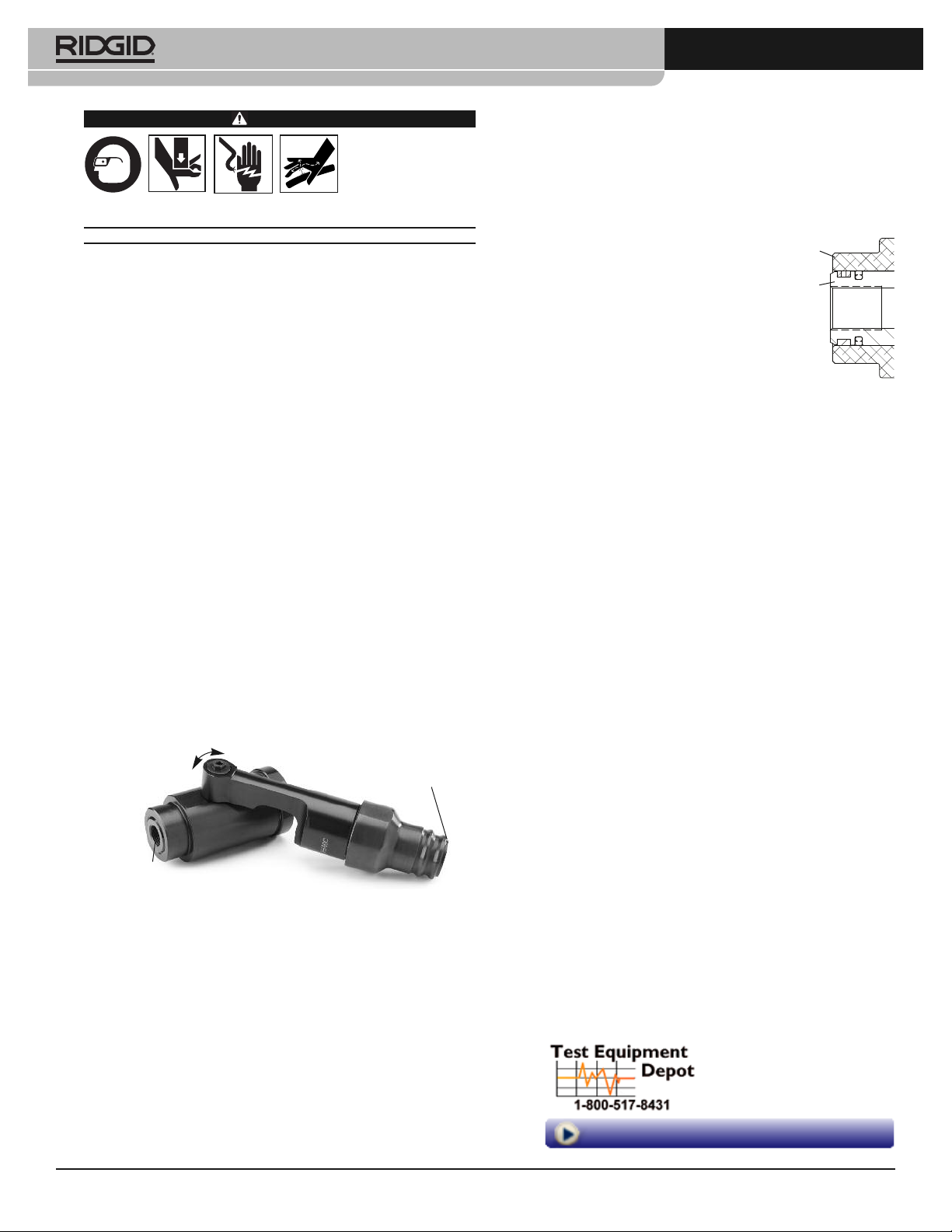
360° Articulation
Inspection/Maintenance
Inspect the Punch Head before each use for issues that could affect safe
use.
1. With the battery removed from the tool, depress the QCS sleeve
and remove the head.
2. Clean the head and remove all dirt, oil, grease, and debris to aid in
inspection and improve control. Pay close attention to the QCS coupling to ensure there is no debris to damage the coupling. Ensure
that the threaded hole is free of debris.
3. Inspect the head for:
• Proper assembly and completeness.
• Wear, corrosion or other damage. Dim-
ples in the grooves of the QCS coupling
are normal with use and are not considered damage.
• Oil Leaks. If the draw stud piston ex-
tends past the tool face (Figure 2), the
oil is low. Have the punch head serviced
– do not attempt to add oil.
• Presence and readability of head mark-
ings.
If any issues are found, do not use head until corrected.
4. Inspect the electrical tool and any other equipment being used as
directed in their instructions. Make sure other knockout components
are in good working condition.
5. The QCS coupling is lubricated for life at the factory and does not
require any further lubrication. Do not disassemble the Punch Head.
Unit contains compressed spring.
Tool Face
Draw Stud
Piston
Figure 2 – Punch Head
Oil Low
QCS Coupling
¾" – 16 UNF Thread For
Draw Stud
Figure 1 – PH-60C Swiv-L-Punch Head
Specification
Material Thickness .............Mild Steel – Up to 10 gauge
Max. Punch Diameter...........Up to 5" (120 mm) in 12 gauge mild steel
Draw Stud Thread ................
Compatible QCS Types......6T QCS
Maximum Output Force......14,600 lbf (64 kN)
Weight.................................4.4 lb (2.0 kg)
Punching capacity depends on a variety of factors including punch
size/configuration, material thickness, type, and hardness. Holes may not
be able to be completed in all cases based on these and other variables.
Printed 11/15
EC41390 REV. A
(0.134", 3.4 mm)
Stainless Steel – Up to 12 gauge
(0.109", 2.8 mm)
and 14 gauge stainless steel
Up to 2" (50,8 mm) in 10 gauge mild steel
and 14 gauge stainless steel
3
/4" – 16 UNF
60kN QCS
99 Washington Street
Melrose, MA 02176
Phone 781-665-1400
Toll Free 1-800-517-8431
Visit us at www.TestEquipmentDepot.com
999-999-526.10
Page 2
PH-60C Swiv-L-Punch™ Head Instructions
Set Up/Operation
These instructions are generalized for many types of knockout punches
and dies. Follow the specific instructions for the set up and operation of
the knockout punch and die being used.
1. Determine the thickness and type of material to be punched. Make
sure there is only a single thickness of material to be punched. Determine the hole size you wish to punch. Select the appropriate
matched punch and die set per manufacturer’s specifications.
2. Make sure all equipment is inspected and set up per manufacturer’s
instructions.
3. Mark the hole location and if needed drill a pilot hole
the draw stud (E.g. for a
3
/4" draw stud, drill a 7/8" pilot hole.)
4. With the Punch Head removed from the tool, thread the draw stud
completely into the Punch Head unit. The thread must be fully engaged to ensure proper operation, but does not need to be tight.
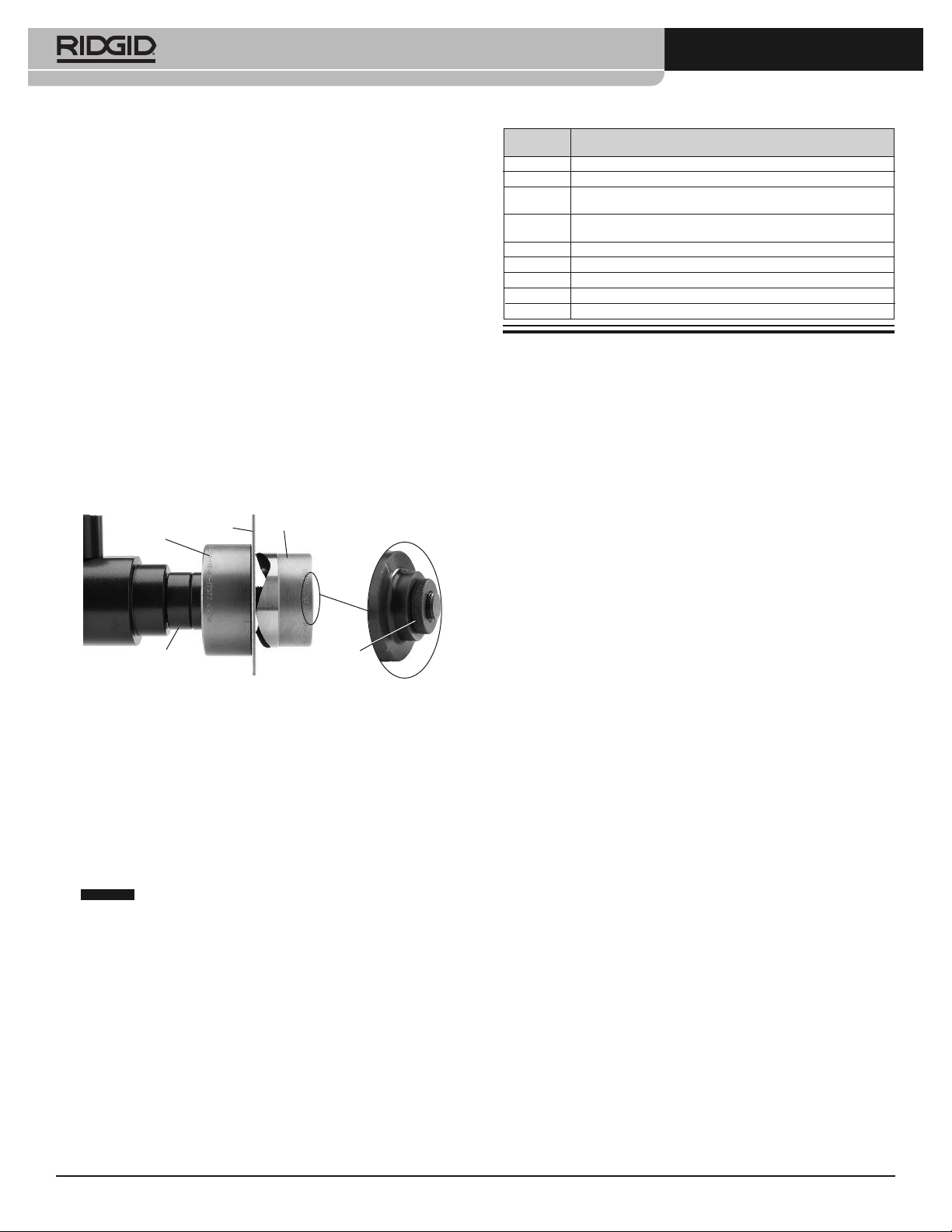
5. Place any needed spacer(s) over the draw stud, followed by the
punch die. Place the cupped half of the die facing away from the tool.
6. Insert the draw stud through the pilot hole in the material to be
punched.
7. Thread the matching punch half of the die onto the draw stud with
the cutting edges toward the material. Tighten by hand until there
are no gaps between the head, spacer(s), die, material and punch.
If there are gaps between the parts, the dies will not be square to the
material and could damage the equipment or cause injury.
A thread adapter is available for use with punches with 1
threads to convert for use with ¾" - 16 UNF draw studs. Fully thread
adapter into the punch as shown in Figure 3 inset.
Punch Die
Material
Punch
1
/8" larger than
1
/8" - 12
Accessories
Catalog
No. Description
23478 Knockout Punch Die Set w/
23492 Knockout Punch Die Set w/21/2", 3", 31/2", 4" and Case
44133 Knockout Punch Die Set w/M 16, 20, 25, 32, 40, 2 draw bolts,
3 spacers and drill
52278 PH-60C Accessories Set w/Drawstuds, Step Bit Drill, Thread
Adapter, and Spacers
52368 ¾ - 16 Draw Stud
52373
3
/8- 24 Draw Stud
52378 Step Bit Drill
52383 11/8- 12 to ¾ - 16 Thread Adapter
52388 Knockout Spacer Set
1
/2", 3/4", 1", 11/4",11/2", 2" and Case
Optional
Spacer(s)
(If Needed)
Figure 3 – Setting Up The Punch Head
11/8– 12
Adapter
Make sure that the punch is fully threaded onto the draw stud. Do
not operate with the punch partially threaded onto the draw stud,
this could damage the stud. If the punch will not fully thread onto
the draw stud, a spacer may need to be removed.
8. Remove the battery from the tool. Depress the QCS sleeve on the
electrical tool and insert the punch head. Release the sleeve to retain the head. Confirm that the head is fully inserted and locked into
tool before turning ON. (If head will not lock into tool, ensure tool
ram is fully retracted by pressing the release button.) With dry hands
install the tool battery.
9. With hands clear of the head and other moving parts, operate the
electrical tool as per its operator’s manual. As soon as the hole is
complete release the run switch.
NOTICE
Do not hold the run switch until the tool automatically retracts.
This could cause the punch to bottom out in the die and damage the
punch/die. Press the electrical tool pressure release button to retract the
ram.
10. Turn the electrical tool OFF and remove the punch from the hole. Be
careful of any sharp edges.
Test Equipment Depot - 800.517.8431 - 99 Washington Street Melrose, MA 02176 - TestEquipmentDepot.com
2
 Loading...