

Page 1

PEX-One Operator’s Manual
Crimp Tool
99 Washington Street
Melrose, MA 02176
Phone 781-665-1400
Toll Free 1-800-517-8431
Visit us at www.TestEquipmentDepot.com
Page 2
PEX-One Crimp Tool
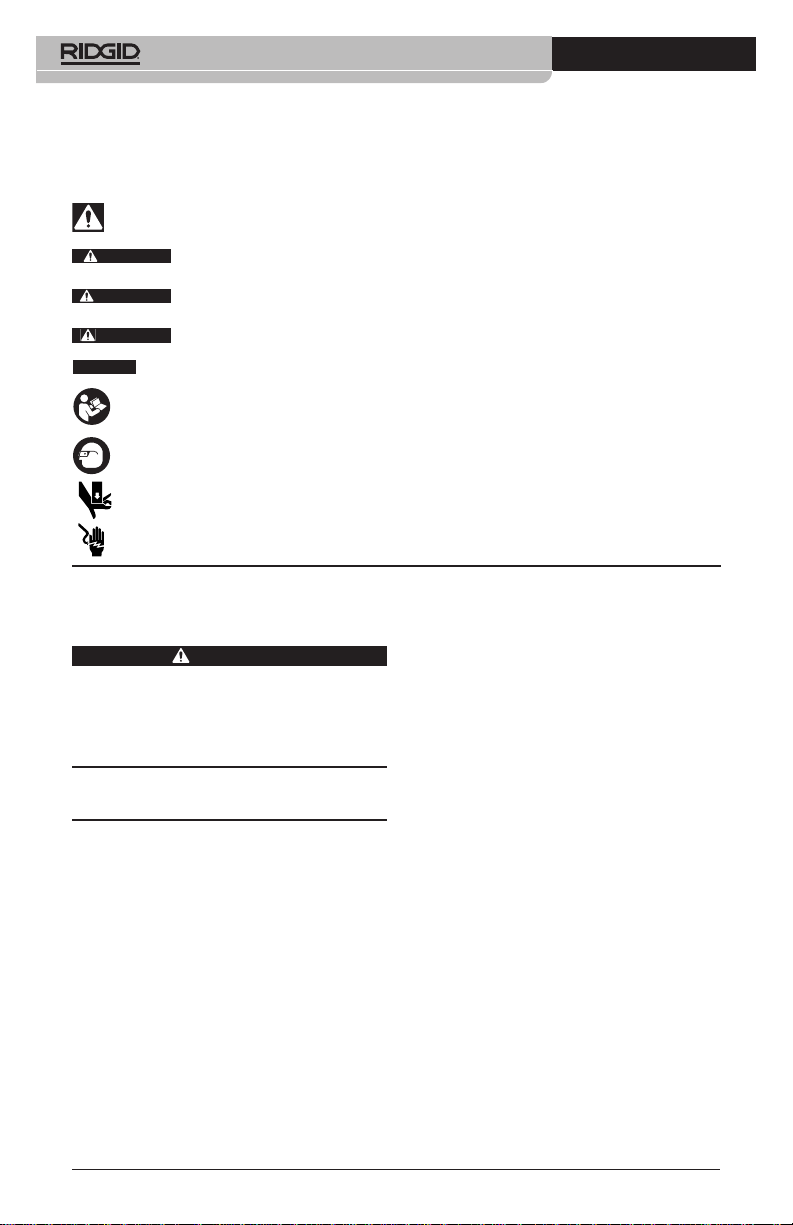
Safety Symbols
In this operator’s manual and on the product, safety symbols and signal words are used to
communicate important safety information. This section is provided to improve understanding of these signal words and symbols.
This is the safety alert symbol. It is used to alert you to potential personal injury hazards.
Obey all safety messages that follow this symbol to avoid possible injury or death.
DANGER
WARNING
CAUTION
NOTICE
DANGER indicates a hazardous situation which, if not avoided, will result in death or
serious injury.
WARNING indicates a hazardous situation which, if not avoided, could result in
death or serious injury.
CAUTION indicates a hazardous situation which, if not avoided, could result in minor
or moderate injury.
NOTICE indicates information that relates to the protection of property.
This symbol means read the operator’s manual carefully before using the equipment. The operator’s manual contains important information on the safe and proper operation of the equipment.
This symbol means always wear safety glasses with side shields or goggles when handling
or using this equipment to reduce the risk of eye injury.
This symbol indicates the risk of hands, fingers or other body parts being crushed..
This symbol indicates the risk of electrical shock.
General Power Tool
Safety Warnings
WARNING
Read all safety warnings, instructions,
illustrations and specifications provided
with this power tool. Failure to follow all
instruc tions listed below may result in
electric shock, fire and/or serious injury.
SAVE ALL WARNINGS
AND INSTRUCTIONS FOR
FUTURE REFERENCE!
The term “power tool” in the warnings refers
to your mains operated (corded) or battery
operated (cordless) power tool.
Work Area Safety
• Keep your work area clean and well lit.
Cluttered or dark areas invite accidents.
• Do not power tools in explosive atmos-
pheres, such as in the presence of flammable liquids, gases or dust. Power tools
create sparks which may ignite the dust
or fumes.
• Keep children and by-standers a way
* The text used in the General Power Tool Safety Warnings section of this manual is verbatim, as required, from the applicable UL/CSA 62841-1 standard. This section contains general safety practices for many different types of power tools. Not
every precaution applies to every tool, and some do not apply to this tool.
2
while operating a power tool. Distrac tions can cause you to lose control.
Electrical Safety
• Power tool plugs must match the outlet.
Never modify the plug in any way. Do
not use any adapter plugs with earthed
(grounded) power tools. Unmodified
plugs and matching outlets will reduce risk
of electric shock.
• Avoid body contact with earthed or
grounded surfaces such as pipes, radiators, ranges and refrigerators. There
is an increased risk of electrical shock if
your body is earthed or grounded.
• Do not expose power tools to rain or
wet conditions. Water entering a power
tool will increase the risk of electrical shock.
• Do not abuse the cord. Never use the
cord for carrying, pulling or unplugging
the power tool. Keep cord away from
heat, oil, sharp edges or moving parts.
Damaged or entangled cords increase the
risk of electric shock.
• When operating a power tool outdoors,
use an extension cord suitable for out-
085-003-980.10_REV. A
Page 3

PEX-One Crimp Tool
door use. Use of a cord suitable for outdoor use reduces the risk of electric shock.
• If operating a power tool in a damp loca-
tion is unavoidable, use a ground fault
circuit interrupter (GFCI) protected supply. Use of a GFCI reduces the risk of elec-
tric shock.
Personal Safety
• Stay alert, watch what you are doing
and use common sense when operating
a power tool. Do not use a power tool
while you are tired or under the influence of drugs, alcohol or medication. A
moment of inattention while operating power
tools may result in serious personal injury.
• Use personal protective equipment. Al -
ways wear eye protection. Protective
equip ment such as dust mask, non-skid
safe ty shoes, hard hat, or hearing protection
used for appropriate conditions will reduce
personal injuries.
• Prevent unintentional starting. Ensure
the switch is in the OFF position before connecting to power source and/or
battery pack, picking up or carrying the
tool. Carrying power tools with your fin-
ger on the switch or energizing power tools
that have the switch ON invites accidents.
• Remove any adjusting key or wrench
be fore turning the power tool ON. A
wrench or a key left attached to a rotating
part of the power tool may result in personal injury.
• Do not overreach. Keep proper footing
and balance at all times. This enables
bet ter control of the power tool in unexpected situations.
• Dress properly. Do not wear loose cloth-
ing or jewelry. Keep your hair, and clothing away from moving parts. Loose
clothes, jewelry, or long hair can be caught
in moving parts.
• If devices are provided for the connec-
tion of dust extraction and collection
facilities, ensure these are connected
and properly used. Use of dust collec-
tion can reduce dust-related hazards.
• Do not let familiarity gained from fre-
quent use of tools allow you to become
complacent and ignore tool safety principles. A careless action can cause severe
injury within a fraction of a second.
Power Tool use and Care
• Do not force power tool. Use the correct
power tool for your application. The cor-
rect power tool will do the job better and
safer at the rate for which it is designed.
• Do not use power tool if the switch does
not turn it ON and OFF. Any power tool
that cannot be controlled with the switch is
dangerous and must be repaired.
• Disconnect the plug from the power
source and/or remove the battery pack, if
detachable, from the power tool before
making any adjustments, changing accessories, or storing power tools. Such
preventive safety measures reduce the risk
of starting the power tool accidentally.
• Store idle power tools out of the reach
of children and do not allow persons
unfamiliar with the power tool or these
instructions to operate the tool. Power
tools are dangerous in the hands of untrained users.
• Maintain power tools and accessories.
Check for misalignment or binding of moving parts, breakage of parts and any other
condition that may affect the power tool’s
operation. If damaged, have the power tool
repaired before use. Many accidents are
caused by poorly maintained power tools.
• Keep cutting tools sharp and clean. Pro -
perly maintained cutting tools with sharp
cutting edges are less likely to bind and are
easier to control.
• Use the power tool, accessories and
tool bits etc. in accordance with these
instructions, taking into account the
working conditions and the work to be
performed. The use of the power tool for
operations different from those intended
could result in a hazardous situation.
• Keep handles and grasping surfaces
dry, clean and free from oil and grease.
Slippery handles and grasping surfaces
do not allow for safe handling and control of
the tool in unexpected situations.
Battery Use & Care
• Recharge only with the charger specified by the manufacturer. A charger that is
suitable for one type of battery pack may
create a risk of fire when used with another battery pack.
• Use power tools only with specifically
designated battery packs. Use of any oth -
085-003-980.10_REV. A
3
Page 4

PEX-One Crimp Tool
er battery packs may create a risk of injury
and fire.
• When a battery pack is not in use, keep
it away from other metal objects, like
paper clips, coins, keys, nails, screws or
other small metal objects that can make
a connection from one terminal to another. Shorting the battery terminals to-
gether may cause burns or a fire.
• Under abusive conditions, liquid may
be ejected from the battery; avoid contact. If contact accidentally occurs, flush
with water. If liquid contacts eyes, additionally seek medical help. Liquid ejected from
the battery may cause irritation or burns.
• Do not use a battery pack or tool that is
damaged or modified. Damaged or modi fied batteries may exhibit unpredictable behavior resulting in fire, explosion or risk of injury.
• Do not expose a battery pack or tool to
fire or excessive temperature. Exposure
to fire or temperature above 265 °F (130 °C)
may cause explosion.
• Follow all charging instructions and do
not charge the battery pack or tool outside the temperature range specified in
the instructions. Charging improperly or at
temperatures outside the specified range
may damage the battery and increase the
risk of fire.
Service
• Have your power tool serviced by a qual i fied repair person using on ly identical
replacement parts.This will ensure that the
safety of the power tool is maintained.
• Never service damaged battery packs.
Service of battery packs should only be
performed by the manufacturer or authorized service providers.
Specific Safety
Information
WARNING
This section contains important safety information that is specific to this tool.
Read these precautions carefully before
using the RIDGID®PEX-One Crimp Tool to
reduce the risk of electrical shock or
other serious injury.
SAVE ALL WARNINGS
AND INSTRUCTIONS FOR
FUTURE REFERENCE!
A compartment in the carrying case is included to keep this manual with the machine
for use by the operator.
Crimp Tool Safety
• Keep your fingers and hands away from
the jaws during the crimping cycle. Your
fingers or hands can be crushed, fractured
or amputated if they become caught between the dies or between these components and any other object.
• Large forces are generated during prod-
uct use that can break or throw parts
and cause injury. Stay clear of the jaws
during use and wear appropriate protective
equipment, including eye protection.
• Never attempt to repair damaged jaws
or dies. Jaws or dies that have been
welded, ground, drilled or modified in
any manner can break during use resulting in serious injury. Discard dam-
aged dies.
• Do not operate the tool without correct
RIDGID dies properly installed in the
jaws. This can damage the tool and/or
cause serious personal injury.
• Use proper tool, die and fitting combina-
tions. Improper combinations can result
in an incomplete or improper crimp, which
increases the risk of leaks, equipment damage and injury.
• Before operating the RIDGID PEX-One
Crimp Tool, read and understand:
– This operator’s manual,
– The battery/charger manual,
– The fitting manufacturer’s installation in-
structions,
– The instructions for any other equipment
used with this tool,
Failure to follow all instructions and warnings may result in property damage and/or
serious injury.
4
085-003-980.10_REV. A
Page 5

PEX-One Crimp Tool
Ridge Tool Company
Elyria, Ohio / USA
Electro Crimp ToolModel No. PEX-One
Serial No.
Description
The RIDGID®PEX-One Crimp Tool is an electro-mechanical tool, which when used with appropriate dies, is designed to crimp fittings
(such as ASTM F1807) to the required dimensions for proper installation.
When operated, an internal electric motor pow ers a screw forward applying force to the jaws
to close the dies on the fitting. The tool automatically retracts when the crimp has been
completed.
The jaw lever is used to open the head to allow
one handed operation. An adjustable hand
strap is supplied that can be mounted to either
side of the tool to improve one handed grip.
The tool head includes a die detent to allow
dies to be quickly and easily changed. A work
light is supplied for better visibility and also to
indicate the tool’s status (tool ON/OFF, temperature out of range, charge battery, etc.).
Hand
Grip
Moveable
Strap Anchor
(one per Tool)
12V
Battery
Figure 1 – PEX-One Crimp Tool
Figure 2
Figure 3 – Machine Serial Number -
Reverse
Warning
Button
Label
Hand Strap
ON/Off
Switch
The first 4 digits (Circled) indicate
the year and month of the manufacture. (12 = year, 06 = month).
Run Switch
Jaws
Fixed
Strap
Anchors
Jaw
Lever
Caddy
Side
Plate
Die
Slot
Work
Light
Detent
Serial
Plate
Die
Dies
Control Marking Description
On/Off Switch
Run Switch — Depress to crimp fitting. Release when crimp complete.
Reverse Button — Allows tool to be reversed without completing crimp. If used, crimp
Jaw Lever — Used to open jaws. Tool will not run when jaws are fully open.
Figure 4 – Controls Chart
085-003-980.10_REV. A
I/O Main tool power switch (I = On, O = Off)
is NOT complete and must be repeated.
5
Page 6

PEX-One Crimp Tool
Mode Light Description/Action
Active ON
Standby
Low
Battery
Battery
Saver
Service Two short flashes Indicates service interval approaching. Will continue until Run
Interval followed by a Switch is pressed, then returns to Active Mode. Starts at 19,000
Approaching pause. cycles. Tool is usable, but tool will lock after service interval.
Service
Figure 5 – Work Light/Status Chart
One brief flash Minimizes battery use. Press and release Run Switch to return to
every two seconds Active Mode.
Slow Flash,
ON 1 second,
OFF 1 second
Light OFF
(ON/OFF
Switch ON)
Rapid Flash.
10 flashes
per second
Tool ready for use. If unused for 5 minutes, tool will move into
Standby Mode.
Battery low. Tool will not run. Change/Recharge battery.
Battery out of specification temperature range. Bring battery
temperature within correct operating range.
Battery very low. Tool will not run. Turn ON/OFF switch OFF.
Change/Recharge battery.
Tool has experienced a fault. Turn ON/OFF switch OFF. Remove
battery for for at least 15 seconds. Replace battery and turn ON/OFF
switch ON. If Service Light continues to flash, take tool for service.
Tool is locked. Tool has completed service interval (20,000 cycles)
and requires service.
Specifications
Crimp Dies Available ...½", ¾" and 1" ASTM
Motor:
Volts...........................12 V DC
Amps ........................30 A DC
Power ........................360 Watts
Duty Cycle...................6 Crimp /minute
Battery.........................12 V Li-Ion
Operating
Temperature ................15° F to 122° F
Weight (tool only).........5.5 lbs (2.5 kg)
Tool Size......................16" × 4.5" × 3"
Standard Equipment
Refer to the RIDGID catalog for details on
equipment supplied with specific tool catalog numbers.
NOTICE
and joining methods is the responsibility of the
6
Selection of appropriate materials
F1807 (See “Option -
al Equipment” Sec tion)
Rechargeable
Battery Pack
(RIDGID RB-1200
Series)
(-10° C to 50° C)
(406 mm x 144 mm
x 76 mm)
system designer and/or installer. Before any installation is attempted, careful evaluation of the
specific service environment, including chemical environment and service temperature
should be completed. Consult fitting system
manufacturer for selection information.
Pre-Operation Inspection
WARNING
Daily before use, inspect your crimp tool
and correct any problems to reduce the
risk of serious injury from electric shock,
crushing injures, jaw failure, and other
causes, and prevent tool damage.
1. Remove battery from tool.
2. Clean any oil, grease or dirt from tool, including handles and controls. This aids inspection and helps prevent tool or control
from slipping from your grip.
3. Inspect crimp tool for:
• Proper assembly, maintenance and
com pleteness.
• Broken, worn, missing, misaligned or
bind ing parts.
085-003-980.10_REV. A
Page 7

PEX-One Crimp Tool
• Presence and readability of tool and
battery warning label.
• Any other condition which may prevent
safe and normal operation.
Do not use Crimp tool until any problems
have been repaired.
4. Wipe the dies clean and inspect. Look for
wear, corrosion, modification, damage or
other issues that may affect safe use. Con firm that dies are clearly marked, matched
to each other and appropriate for the application. Do not use damaged, mismatched
or otherwise inappropriate dies.
Inspect the press profile. Clean if needed
(see Maintenance section).
5. Inspect and maintain any other equipment being used per its instructions to
make sure it is functioning properly.
Setup and Operation
Instructions
WARNING
Keep your fingers and hands away from
the Jaws during the crimping cycle. Your
fingers or hands can be crushed, fractured or amputated if they become caught
between the dies or between these components and any other object.
Large forces are generated during product use that can break or throw parts
and cause injury. Stay clear of the jaws
during use and wear appropriate protective equipment, including eye protection.
Do not operate the tool without correct
RIDGID dies properly installed in the
jaws. This can damage the tool and/or
cause serious personal injury.
Use proper tool, die and fitting combinations. Improper combinations can result in an incomplete or improper crimp,
which increases the risk of leaks, equipment damage and injury.
Follow set up and operating instructions
to reduce the risk of injury from crushing,
electrical shock and other causes and to
prevent tool damage.
in clear, level, stable, dry location. Do not
use tool while standing in water.
2. Inspect work to be done and determine
correct RIDGID tool and dies for the application per their specifications. Using incorrect equipment for an application can
cause injury, damage the tool and make
incomplete connections.
3. Make sure all equipment has been inspected and set up as directed in their instructions.
Hand Strap
Depending on user’s preference, the hand
strap can be attached to either side of tool.
1. If needed, remove strap anchor screws
and reattach to other side of tool. Confirm
screws are secure (Figure 6A).
2. Route strap through strap anchors as
shown in Figure 6B. Secure strap in place
with hook and loop fasteners. Adjust strap
length as desired for hand fit.
Alternate
Anchor Location
A
B
Figure 6 – Strap Installation
Moveable
Strap Anchor
Removing/Installing Dies
1. Remove battery from tool.
2. Depress and hold jaw lever to fully open
tool jaws.
3. Dies are removed/installed by depressing
the die detent and moving the die in/out
of the jaws (see Figure 7). Die detent will
hold dies in place.
1. Confirm appropriate work area (See Gen -
eral Power Tool Safety Warn ings). Operate
085-003-980.10_REV. A
7
Page 8

PEX-One Crimp Tool
Die Detent
Crimp
Profile
Figure 7 – Removing and Installing Dies
Dies should fit snugly and securely. With jaws
closed, dies should align. Always use a matched
set of RIDGID dies. If there are any issues regarding proper die fit, do not use tool. Do not
operate tool without dies installed.
Size ASTM F1807
½" Bronze
¾" Silver
1" Gold
Figure 8 – Die Identification Chart
(Marked “ASTM”)
Die Caddy
Die caddy is available to hold dies when not in
use. For convenience, it can be clipped to the
crimp tool (Figure 9) or belt. Dies push in/pull
out and are held in place by a spring.
Clip
Figure 9 – Die Caddy Use
Dies
Preparing Connection
Prepare connection per fitting manufacturer’s
instructions. Confirm that fitting is fully inserted
into tube and any ring/sleeve is properly placed.
NOTICE
practices for multiple fitting systems. Always
follow fitting manufacturers specific installation instructions to reduce risk of improper
connections and extensive property damage.
These instructions are generalized
Crimping Fitting
1. Make sure that proper dies for application
have been installed.
2. With dry hands, install a fully charged
bat tery into crimp tool. Move ON/OFF
(I/O) switch to ON (I) position. The work
lights should come on. See Work light/sta-
tus chart for other tool conditions.
3. Depress jaw lever to fully open jaws.
4. Place dies squarely over fitting, aligning the
contour of die to fitting. Release jaw lever
so dies sit on fitting. (Figure 10). Improper
tool alignment can result in an improper
crimp, cause leaks or damage tool. Do
not hang tool from fitting.
Figure 10 – Tool Square to Fitting
5. Reconfirm that the fitting is appropriately
positioned. Remove your thumb from jaw
lever. Keep fingers and hands away from
jaws to reduce risk of crushing injuries between dies and between jaws and surroundings.
Depress and hold run switch to operate
tool. When the crimp is complete, the
tool will automatically reverse to start position. Release run switch.
If run switch is released prior to crimp
completion, tool will stop and crimp cannot be completed. Depress reverse button
(Figure 1) and crimp connection again.
Use this procedure in case of emergency,
if tool must be removed before a crimp is
completed or if tool malfunctions during a
crimp.
NOTICE
pressed, crimp is NOT complete and the connection must be crimped again to ensure
completion.
6. With crimp complete, depress jaw lever to
Any time reverse button is de-
open jaws and remove from fitting. Avoid
8
085-003-980.10_REV. A
Page 9

PEX-One Crimp Tool
any sharp edges that may have formed
on the crimped connection.
7. When operation is complete, move ON/ OFF (I/O) switch to OFF (O) and remove
the battery.
Inspecting the Crimped
Connection
1. Visually inspect crimped connection for:
• Tube not fully inserted.
• Incorrect placement, distortion or de-
formation of crimped sleeve/ring.
• Any other issues per fitting manufac-
turer.
If any issues are found, remove fitting
and install a new connection.
2. Check crimp size as required for system
by fitting manufacturer:
• ASTM F1807 crimped connections are
checked with a GO/NO GO gauge. Us ing correct gauge, hold gauge perpendicular to axis of tube. A crimp is good if
GO gauge fits over ring, and NO GO
gauge does not.
Figure 11 – Correct Go Gauge Fit
3. Test connection in accordance connector
manufacturer instructions, normal practice and applicable codes.
Storage
Remove battery from tool. Store crimp tool
and battery in case. Avoid storing in extreme
heat or cold. The tool will not turn ON if the tool
is outside the specification range. This will be
indicated by the work light (see Figure 5).
WARNING
Store tool in a dry, secured
area that is out of reach of children and people
unfamiliar with the RIDGID PEX-One Crimp
Tool. The Crimp tool is dangerous in the hands
of untrained users.
Maintenance
Instructions
WARNING
Make sure battery is removed from tool
before performing maintenance or making any adjustment.
Cleaning and Lubrication
1. After each use, wipe any oil or dirt off
the crimp tool and dies with a clean, dry,
soft cloth.
2. Check jaw lever operation with each use.
Tool head should open and close freely
with only moderate finger effort required.
3. Clean the die crimp profile with steel wool,
steel bristle wire brush, or fine grade
Scotch-Brite
trademark of the 3M Company). Do not
use aggressive cleaning methods that
may alter critical crimp profile dimensions
(see Figure 7).
4. Tool is lubricated for life from the factory
and does not require any further lubrication.
®
(Scotch-Brite is a registered
Troubleshooting
PROBLEM POSSIBLE REASON SOLUTION
Dies will not open
enough to go over
fitting.
Tool will not turn ON
when ON/OFF switch
is turned ON.
Tool will not operate.
See Figure 5 - Work Light/Status Chart for Light Diagnostic Codes.
085-003-980.10_REV. A
The tool is not fully retracted.
Battery is completely discharged or battery has failed.
Battery not properly inserted into the
tool.
Tool has been run FORWARD (Not fully
retracted.)
Press the REVERSE button.
Insert fully charged battery.
Check to assure battery is fully inserted.
Press the REVERSE button.
9
Page 10

PEX-One Crimp Tool
Required Maintenance By
RIDGID Independent Service
Center
The PEX-One Crimp Tool must be serviced at
set intervals by a RIDGID Independent Service
Center to ensure proper operation. This will
be indicated by the Tool Work/Status light (See
Figure 6).
Service and Repair
WARNING
Improper service or repair can make the
machine unsafe to operate.
Service and repair on the PEX-One Crimp
Tool must be performed by a RIDGID Inde pendent Service Center. Use only RIDGID
service parts.
Optional Equipment
Disposal
Parts of this tool contain valuable
materials and can be recycled. There are
companies
may be found locally. Dispose of the
components in compli-ance with all
applicable regulations. Contact your local
waste management authority for more
information.
imple men tation into national legislation, electrical equipment that is no longer usable must
be collected separately and disposed of in
an environmentally correct manner.
that specialize in recycling that
For EC Countries: Do not dispose
of elec trical equipment with household waste!
According to the European Guide line 2012/ 19/EU for Waste Elec trical
and Electronic Equipment and its
WARNING
To reduce the risk of injury, only use e quipment specifically designed and recommended for use with the RIDGID PEXOne Crimp Tool, such as listed below.
Catalog
No. Description
54253 PEX-One Tool Kit (ASTM)
56638 PEX-One Tool Only
56568 ASTM Die Kit (1/2", 3/4", 1")
56573 ASTM Die Set 1/2"
56578 ASTM Die Set 3/4"
56583 ASTM Die Set 1"
56608 Bag, 20", Soft-Sided
56603 Die Caddy
29583 Go-No Go Gauges (ASTM)
Battery Packs
Catalog
RBC-121 Chargers and Cords
Catalog Plug
All listed batteries will work with any catalog number RBC-121
Battery Charger.
Capacity
No. Region
55183 12V 2.5Ah All
No. Region Type
55193 Charger USA, Canada and Mexico A
44798 Charger Cord North America A
EC Declaration of
Conformity
The EC Declaration of Conformity (890-011-
320.10) will accompany this manual as a separate booklet when required
Electromagnetic
Compatibility (EMC)
The term electromagnetic compatibility is
taken to mean the capability of the product to
function smoothly in an environment where
electromagnetic radiation and electrostatic
discharges are present and without causing
electromagnetic interference to other equipment.
NOTICE
EMC standards. However, the possibility of
it causing interference in other devices cannot
be precluded. All EMC related standards that
have been tested are called out in the tool’s
technical document.
This tool conforms to all applicable
10
085-003-980.10_REV. A
Page 11

99 Washington Street
Melrose, MA 02176
Phone 781-665-1400
Toll Free 1-800-517-8431
Visit us at www.TestEquipmentDepot.com
Printed 12/16 085-003-980.10
EC41808 REV. A
The Emerson logo and RIDGID logo are registered trademarks of Emerson Electric Co. or RIDGID, Inc. in the U.S. and other countries.
©2016, RIDGID, Inc.
All other trademarks belong to their respective holders.
 Loading...