

RIDGID micro DM-100 Operator's Manual
p. 1
p. 21
p. 41
p. 61
p. 83
p. 105
p. 125
p. 145
p. 165
p. 185
p. 205
p. 225
p. 247
p. 267
p. 287
p. 307
p. 327
p. 349
p. 369
p. 389
p. 409
p. 433
EN
FR
ES
DE
NL
IT
PT
SV
DA
NO
FI
PL
CZ
SK
RO
HU
EL
HR
SL
SR
RU
TR
RIDGE TOOL COMPANY
micro
DM-100

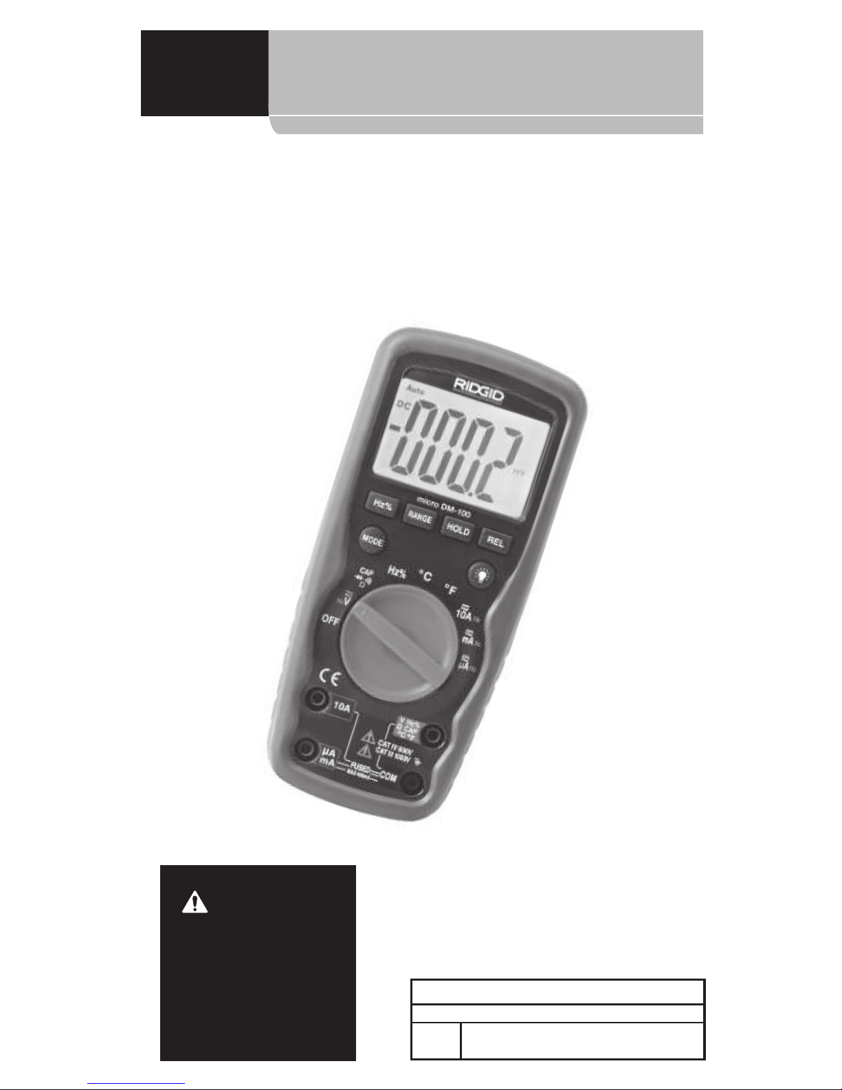
micro DM-100 Digital Multimeter
Record Serial Number below and retain product serial number which is located on nameplate.
Serial
No.
micro DM-100
Digital Multimeter
WARNING!
Read this Operator’s Manual
carefully before using this
tool. Failure to understand
and follow the contents of
this manual may result in
electrical shock, re and/or
serious personal injury.
micro DM-100

micro DM-100 Digital Multimeter
2
Lifetime Warranty ...................................................................................................... Back Cover
*Original instructions
Table of Contents
Table of Contents ........................................................................................................................... 2
Safety Symbols ................................................................................................................................3
General Safety Rules .................................................................................................................... 3
Work Area Safety .......................................................................................................................... 3
Electrical Safety ............................................................................................................................. 3
Personal Safety .............................................................................................................................. 3
Equipment Use and Care .......................................................................................................... 4
Service .............................................................................................................................................. 4
Speci c Safety Information ...................................................................................................... 4
Multimeter Safety ........................................................................................................................ 4
Description, Speci cations And Standard Equipment .............................................. 5
Description ..................................................................................................................................... 5
Speci cations................................................................................................................................. 5
Standard Equipment .................................................................................................................. 8
Controls ............................................................................................................................................ 8
Icons .................................................................................................................................................. 9
FCC Statement ...............................................................................................................................10
Electromagnetic Compatibility (EMC) ..............................................................................10
Changing/Installing Batteries ...............................................................................................10
Pre-Operation Inspection .......................................................................................................11
Set-Up and Operation ...............................................................................................................12
Rotary Function Switch ................................................................................................................13
Input Terminals ...........................................................................................................................13
Pushbuttons .................................................................................................................................14
DC/AC Voltage Measurement ...............................................................................................14
DC/AC Current Measurement ...............................................................................................15
Resistance Measurement ........................................................................................................15
Diode Test ......................................................................................................................................16
Continuity Check ........................................................................................................................16
Capacitance Measurement ....................................................................................................16
Frequency Measurement........................................................................................................17
Temperature Measurement ...................................................................................................17
Maintenance Instructions .......................................................................................................18
Cleaning .........................................................................................................................................18
Calibration.....................................................................................................................................18
Fuse Replacement .....................................................................................................................18
Accessories ......................................................................................................................................18
Storage ..............................................................................................................................................19
Service and Repair.......................................................................................................................19
Disposal.............................................................................................................................................19
Battery Disposal ...........................................................................................................................19
Troubleshooting ...........................................................................................................................20
micro DM-100 Digital Multimeter
3
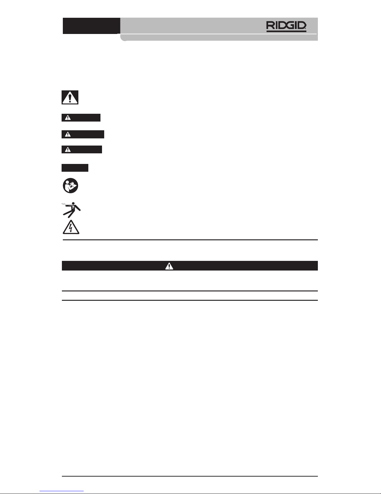
Safety Symbols
In this operator’s manual and on the product, safety symbols and signal words are used
to communicate important safety information. This section is provided to improve understanding of these signal words and symbols.
This is the safety alert symbol. It is used to alert you to potential personal injury
hazards. Obey all safety messages that follow this symbol to avoid possible injury
or death.
DANGER
WARNING
CAUTION
NOTICE
DANGER indicates a hazardous situation which, if not avoided, will result
in death or serious injury.
WARNING indicates a hazardous situation which, if not avoided, could result in death or serious injury.
CAUTION indicates a hazardous situation which, if not avoided, could result
in minor or moderate injury.
NOTICE indicates information that relates to the protection of property.
This symbol means read the operator’s manual carefully before using the equipment. The operator’s manual contains important information on the safe and proper operation of the equipment.
This symbol indicates the presence of a high voltage hazard.
This symbol indicates the risk of electrical shock.
General Safety Rules
WARNING
Read all safety warnings and in struc tions. Failure to follow the warn ings and instructions may result in electric shock, re and/or serious injury.
SAVE THESE INSTRUCTIONS!
Work Area Safety
• Keep your work area clean and well lit. Cluttered or dark areas invite accidents.
• Do not operate equipment in explosive atmospheres, such as in the presence of
ammable liquids, gases or dust. Equipment can create sparks which may ignite the dust
or fumes.
• Keep children and by-standers away while operating equipment. Distractions can
cause you to lose control.
Electrical Safety
• Avoid body contact with earthed or grounded surfaces such as pipes, radiators, ranges
and refrigerators. There is an increased risk of electrical shock if your body is earthed or
grounded.
• Do not expose equipment to rain or wet conditions. Water entering equipment will
increase the risk of electrical shock.
Personal Safety
• Stay alert, watch what you are doing and use common sense when operating
equipment. Do not use equipment while you are tired or under the in uence of
drugs, alcohol or medication. A moment of inattention while operating equipment
may result in serious personal injury.

micro DM-100 Digital Multimeter
4
• Use personal protective equipment. Always wear eye protection. Protective equip-
ment such as as protective gloves and clothing, dust mask, non-skid safety shoes, hard
hat, or hearing protection used for appropriate conditions will reduce personal injuries.
• Do not overreach. Keep proper footing and balance at all times. This enables better
control of the equipment in unexpected situations.
Equipment Use and Care
• Do not force equipment. Use the correct equipment for your application. The cor-
rect equipment will do the job better and safer at the rate for which it is designed.
• Do not use equipment if the switch does not turn it ON and OFF. Any tool that can-
not be controlled with the switch is dangerous and must be repaired.
• Store idle equipment out of the reach of children and do not allow persons unfa-
miliar with the equipment or these instructions to operate the equipment. Equipment can be dangerous in the hands of untrained users.
• Maintain equipment. Check for missing parts, breakage of parts and any other condi-
tion that may a ect the equipment’s operation. If damaged, have the equipment repaired before use. Many accidents are caused by poorly maintained equipment.
• Use the equipment and accessories in accordance with these instructions, tak-
ing into account the working conditions and the work to be performed. Use of the
equipment for operations di erent from those intended could result in a hazardous situation.
• Use only accessories that are recommended by the manufacturer for your equip-
ment. Accessories that may be suitable for one piece of equipment may become hazardous when used with other equipment.
• Keep handles dry and clean; free from oil and grease. Allows for better control of the
equipment.
Service
• Have your equipment serviced by a quali ed repair person using on ly identical
replacement parts. This will ensure that the safety of the tool is maintained.
Specific Safety Information
WARNING
This section contains important safety information that is speci c to this tool.
Read these precautions carefully before using the RIDGID® micro DM-100 Digital
Multimeter to reduce the risk of electrical shock or other serious injury.
SAVE THESE INSTRUCTIONS!
Keep this manual with the tool for use by the operator.
Multimeter Safety
• Use caution when working with voltages above 30 V AC RMS, 42 V AC peak or 60
V DC. These voltages pose serious shock hazard. High-voltage circuits, both DC and AC,
are very dangerous and should be measured with great care. Avoid working alone.
• Do not connect to voltages that exceed 600 VAC or VDC relative to earth ground.
This may damage the meter and expose the operator to a shock hazard.
• When using the probes, keep your ngers behind the nger guards on the probes.
This reduces the risk of electric shock.
• Never ground yourself when taking electrical measurements. Do not touch exposed
metal pipes, outlets, xtures, etc., which might be at ground potential. Keep your body
isolated from ground using appropriate methods.

micro DM-100 Digital Multimeter
5
• When measuring current, turn o the circuit power before connecting the meter in
series with the circuit. Improper set up could result in electrical shock.
• When measuring resistance, disconnect all power (remove batteries, unplug cord,
discharge all capacitors, etc.) to the circuit being measured. This reduces the risk of
electric shock.
• After resistance test, the capacitive circuits must be discharged. This will help pro-
tect against electric shock.
• Use extreme caution when working near bare conductors and bus bars. Accidental
contact with conductors could result in electrical shock.
• Turn o power to the circuit under test before cutting, unsoldering, or breaking the
circuit. Small amount of current can expose the operator to a shock hazard.
The EC Declaration of Conformity (890-011-320.10) will accompany this manual as a separate booklet when required.
If you have any question concerning this RIDGID® product:
• Contact your local RIDGID distributor.
• Visit www.RIDGID.com or www.RIDGID.eu to nd your local RIDGID contact point.
• Contact RIDGID Technical Services Department at rtctechservices@emerson.com, or in
the U.S. and Canada call (800) 519-3456.
Description, Specifications And Standard Equipment
Description
The RIDGID® DM-100 Digital Multimeter is a handheld instrument. The unit can measure DC
and AC Voltage and Current, Resistance, Capacitance, Frequency, Temperature, Continuity
(audible signal) and Test Diodes. The multimeter can automatically select the best range
for measurement.
The unit has data hold and relative measurement functions. Overload protection and low
battery indication are provided. The unit has a 4000-count backlight LCD.
The multimeter is powered by a 9V battery and has auto power-o function after 15 minutes of inactivity.
Specifications
Display ................................................................4000 Count backlight LCD
Overvoltage Category ..................................CAT III 1000V, CAT IV 600V
Fuse Rating ........................................................0.5A/1000V Fast Blow for the 400mA Range,
10A/1000V Fast Blow for the 10A Range
Insulation ...........................................................Class 2, Double Insulation
Protection Rating ............................................IP 67
Polarity ................................................................Auto Polarity Indication
Operating Temperature ...............................0°C to 50°C (32°F to 122°F)
Power Supply ...................................................9V Battery, NEDA 1604, IEC 6F22 or 6LR61
Weight .................................................................0.82 lbs (375 g)
Dimension .........................................................7.2" x 3.2" x 2.2" (182 x 82 x 55 mm)
 Loading...