

Page 1
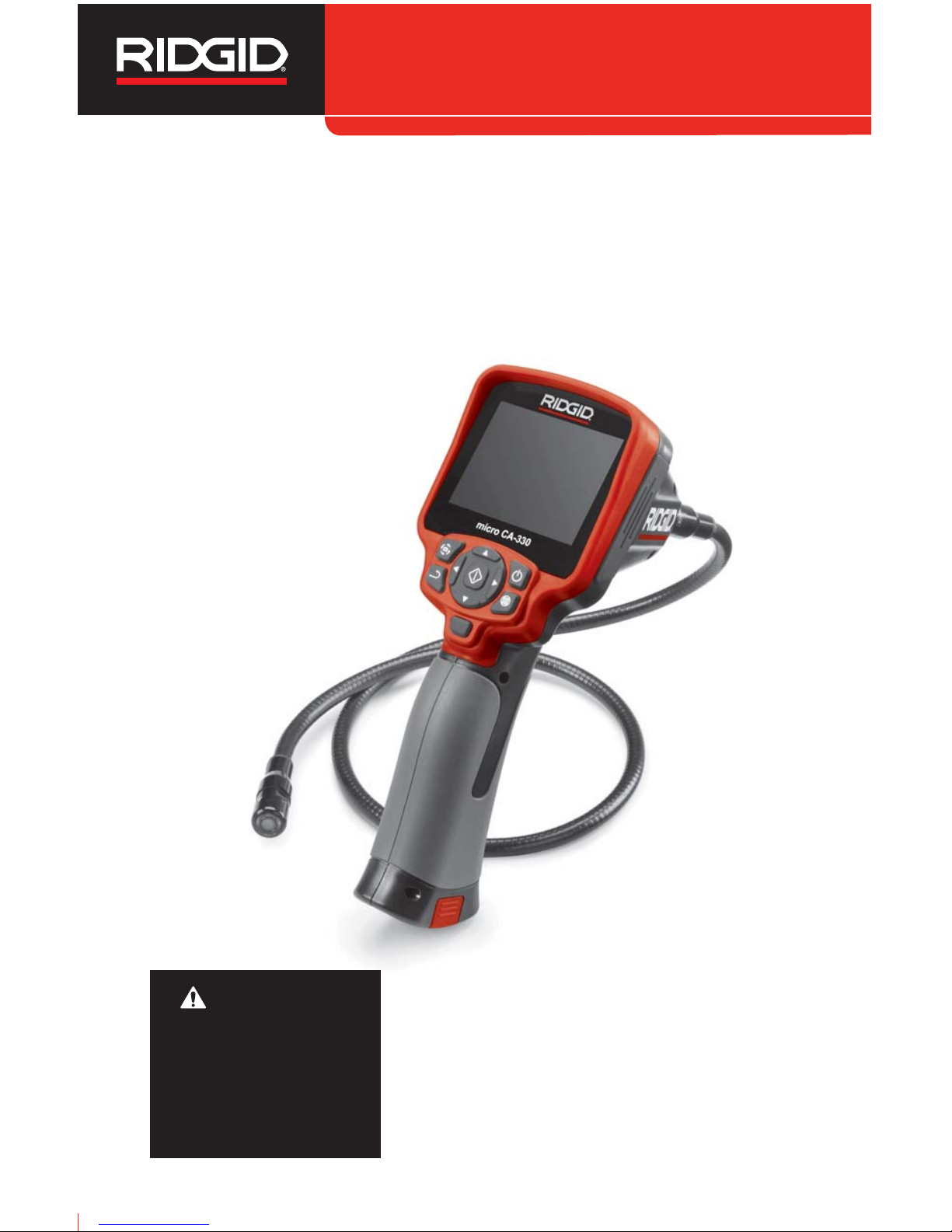
micro CA-330
Inspection Camera
• Français – 21
• Castellano – pág. 43
WARNING!
Read this Operator’s Man ual
carefully before using this
tool. Failure to understand
and follow the contents of this
manual may result in electrical shock, fire and/or serious
person al injury.
micro CA-330 Operator’s Manual
Page 2

ii
micro CA-330 Inspection Camera
Table of Contents
Safety Symbols ..............................................................................................................................2
General Safety Information
Work Area Safety........................................................................................................................2
Electrical Safety..........................................................................................................................2
Personal Safety...........................................................................................................................2
Equipment Use and Care ...........................................................................................................2
Service........................................................................................................................................3
Specific Safety Information
micro CA-330 Inspection Camera Safety....................................................................................3
Description, Specifications and Standard Equipment
Description..................................................................................................................................4
Specifications..............................................................................................................................4
Standard Equipment...................................................................................................................4
Controls ......................................................................................................................................5
FCC Statement ...............................................................................................................................5
Electromagnetic Compatibility (EMC)..........................................................................................5
Icons................................................................................................................................................6
Tool Assembly
Changing/Installing Batteries......................................................................................................6
Powering with the AC Adapter ....................................................................................................6
Installing Imager Head Cable or Extension Cables ....................................................................7
Installing Accessories .................................................................................................................7
Installing SD™ Card ...................................................................................................................7
Pre-Operation Inspection..............................................................................................................7
Tool and Work Area Set-Up...........................................................................................................8
Operating Instructions ..................................................................................................................9
Live Screen.................................................................................................................................9
Image Adjustment.....................................................................................................................10
Image Capture..........................................................................................................................10
Audio Recording .......................................................................................................................10
Menu.........................................................................................................................................10
Mode.........................................................................................................................................11
Access Files by Wi-Fi................................................................................................................11
Time Stamp ..............................................................................................................................11
Language..................................................................................................................................11
Date/Time .................................................................................................................................11
TV-Out ......................................................................................................................................11
Update Firmware ......................................................................................................................11
Speaker/Microphone.................................................................................................................11
Auto Power OFF .......................................................................................................................12
Factory Reset ...........................................................................................................................12
Bluetooth®.................................................................................................................................12
Wi-Fi .........................................................................................................................................12
About ........................................................................................................................................12
Transferring Files ......................................................................................................................12
Connecting to TV......................................................................................................................12
Using a Bluetooth Microphone..................................................................................................13
Using with SeeSnake®Inspection Equipment ..................................................................................13
Maintenance
Reset Function..........................................................................................................................14
Accessories..................................................................................................................................14
Storage..........................................................................................................................................14
Service and Repair.......................................................................................................................14
Disposal........................................................................................................................................14
Troubleshooting...........................................................................................................................15
Battery Pack/Battery Charger Safety .........................................................................................16
Description and Specifications ..................................................................................................17
Charger Inspection and Set-Up ..................................................................................................17
Charging Procedure/Operating Instructions.............................................................................18
Cleaning Instructions ..................................................................................................................18
Accessories..................................................................................................................................18
Storage..........................................................................................................................................18
Service and Repair.......................................................................................................................19
Disposal........................................................................................................................................19
Lifetime Warranty...........................................................................................................Back Cover
*Original Instructions - English
Page 3
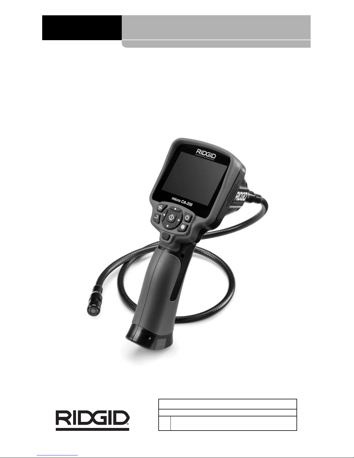
micro CA-330
Inspection Camera
microCA-330
micro CA-330 Inspection Camera
Record Serial Number below and retain product serial number which is located on nameplate.
Serial
No.
Page 4
Safety Symbols
In this operator’s manual and on the product, safety symbols and signal words are used to
communicate important safety information. This section is provided to improve understanding of these signal words and symbols.
This is the safety alert symbol. It is used to alert you to potential personal injury hazards. Obey
all safety messages that follow this symbol to avoid possible injury or death.
DANGER indicates a hazardous situation which, if not avoided, will result in death or
serious injury.
WARNING indicates a hazardous situation which, if not avoided, could result in
death or serious injury.
CAUTION indicates a hazardous situation which, if not avoided, could result in minor
or moderate injury.
NOTICE indicates information that relates to the protection of property.
This symbol means read the operator’s manual carefully before using the equipment. The operator’s manual contains important information on the safe and proper operation of the equipment.
This symbol means always wear safety glasses with side shields or goggles when handling
or using this equipment to reduce the risk of eye injury.
This symbol indicates the risk of hands, fingers or other body parts being caught or wrapped
in gears or other moving parts.
This symbol indicates the risk of electrical shock.
• Do not expose equipment to rain or
wet conditions. Water en tering equipment will increase the risk of electrical
shock.
Personal Safety
• Stay alert, watch what you are doing
and use common sense when operating equipment. Do not use equipment
while you are tired or under the influence of drugs, alcohol or medication. A
moment of inattention while operating
equipment may result in serious personal
injury.
• Do not overreach. Keep proper footing
and balance at all times. This enables
better control of the power tool in unexpected situations.
• Use personal protective equipment.
Always wear eye protection. Protective
equipment such as dust mask, non-skid
safety shoes, hard hat or hearing protection
used for appropriate conditions will reduce
personal injuries.
Equipment Use and Care
• Do not force equipment. Use the correct
equipment for your application. The cor-
rect equipment will do the job better and
safer at the rate for which it is designed.
2
micro CA-330 Inspection Camera
General Safety
Information
WARNING
Read all safety warnings and instructions. Failure to follow the warnings and
instructions may result in electric shock,
fire and/or serious injury.
SAVE THESE INSTRUCTIONS!
Work Area Safety
• Keep your work area clean and well lit.
Cluttered or dark areas invite accidents.
• Do not operate equipment in explosive
atmospheres, such as in the presence
of flammable liquids, gases or dust. E -
quip ment can create sparks which may ignite the dust or fumes.
• Keep children and by-standers a way
while operating equipment. Distrac tions
can cause you to lose control.
Electrical Safety
• Avoid body contact with earthed or
ground ed surfaces such as pipes, radiators, ranges and refrigerators. There is
an increased risk of electrical shock if your
body is earthed or grounded.
NOTICE
DANGER
WARNING
CAUTION
Page 5

tion Cam era to reduce the risk of electrical shock or other serious injury.
SAVE THESE INSTRUCTIONS!
A manual holder is supplied in the carrying
case of the micro CA-330 Inspection Camera
to keep this manual with the tool for use by
the operator.
micro CA-330 Inspection
Camera Safety
• Do not expose the display unit to water
or rain. This increases the risk of electrical shock. The micro CA-330 imager head
and ca ble are waterproof. The hand-held
display unit is not.
• Do not place the micro CA-330 Inspec -
tion Cam era anywhere that may contain a live electrical charge. This in-
creases the risk of electrical shock.
• Do not place the micro CA-330 Inspec -
tion Cam era anywhere that may contain moving parts. This increases the
risk of entanglement injuries.
• Do not use this device for personal in-
spection or medical use in any way.
This is not a medical device. This could
cause personal injury.
• Always use appropriate personal pro-
tective equipment while handling and
using the micro CA-330 Inspection Cam er a. Drains and other areas may contain
chemicals, bacteria and other substances
that may be toxic, infectious, cause burns
or other issues. Appropriate personal
protective equipment always includes
safety glasses and gloves, and may in-
clude equipment such as latex or rubber
gloves, face shields, goggles, protective
clothing, respirators and steel-toed foot wear.
• Practice good hygiene. Use hot, soapy
wa ter to wash hands and other body parts
exposed to drain contents after handling or
using the micro CA-330 In spec tion Camera
to inspect drains and other areas that may
contain chemicals or bacteria. Do not eat or
smoke while operating or handling the
micro CA-330 Inspection Camera. This
will help prevent contamination with toxic or
infectious material.
• Do not operate the micro CA-330 In -
spection Camera if operator or device is
standing in water. Operating an electrical
• Do not use equipment if the switch
does not turn it ON and OFF. Any tool
that cannot be controlled with the switch is
dangerous and must be repaired.
• Disconnect the batteries from the e quip-
ment before making any adjustments,
changing accessories, or storing. Such
preventive safety measures reduce the risk
of injury.
• Store idle equipment out of the reach of
children and do not allow persons unfamiliar with the equipment or these instructions to operate the equipment.
Equipment can be dangerous in the hands
of untrained users.
• Maintain equipment. Check for missing
parts, breakage of parts and any other
condition that may affect the equipment’s
operation. If damaged, have the equipment repaired before use. Many accidents
are caused by poorly maintained equipment.
• Use the equipment and accessories in
accordance with these instructions,
taking into account the working conditions and the work to be performed.
Use of the equipment for operations different from those intended could result in a
hazardous situation.
• Use only accessories that are recom-
mended by the manufacturer for your
equipment. Accessories that may be suit-
able for one piece of equipment may become hazardous when used with other
equipment.
• Keep handles dry and clean; free from
oil and grease. Allows for better control of
the equipment.
Service
• Have your equipment serviced by a
qual i fied repair person using on ly identical replacement parts. This will ensure
that the safety of the tool is maintained.
Specific Safety
Information
WARNING
This section contains important safety information that is specific to the inspection camera.
Read these precautions carefully before
using the RIDGID®micro CA-330 In spec -
3
micro CA-330 Inspection Camera
Page 6

Imager and Cable
are Water proof to 3.3'
(1 m), IP67
Min. Cable
Bend Radius................5" (13 cm)
Photo Format...............JPEG
Image Resolution ........640 x 480
Video Format...............MP4
Video Resolution .........320 x 240
Frame Rate..................up to 30 FPS
Digital Zoom ................2X
Handheld Unit Ingress
Protection Rating.........IP65
TV-Out.........................PAL/NTSC
User selectable
Built-In Memory ...........235 MB Memory
External Memory .........SD™ Card 32 GB
max (4 GB supplied)
Data Output.................USB Data Cable,
SD™ Card and
Wi-Fi.
Bluetooth Max. Range...16.4' (5 m)
Wi-Fi Max Range.........33' (10 m)
Operating
Temperature ................32 to 113°F
(0 to 45°C)
Storage Temperature...-4°F to 140°F
(-20°C to 60°C)
Power Supply ...............Li-Ion Battery or AC
Adapter 5 V, 1.5 Amp
Weight...........................5.5 lbs (2,5 kg)
Standard Equipment
The micro CA-330 Inspection Camera comes
with the following items:
• micro CA-330 Handset
• 17 mm Imager
• 3' (90 cm) USB Cable
• 3' (90 cm) RCA Cable with Audio
• Hook, Magnet, Mirror Attachments
• Li-Ion Battery
• Li-Ion Battery Charger with Cord
• AC Adapter
• Headset Accessory with Microphone
• 4 GB SD™ Card
• Operator’s Manual Pack
device while in water increases the risk
of electrical shock.
• Do not allow use in wireless mode with
a separate monitor to distract you from
proper CA-330 use. Distractions increase
the risk of injury.
The EC Declaration of conformity (890-011-
320.10) will accompany this manual as a separate booklet when required.
If you have any question concerning this
RIDGID
®
product:
– Contact your local RIDGID distributor.
– Visit www.RIDGID.com or
www.RIDGID.eu to find your local
RIDGID contact point.
– Contact Ridge Tool Technical Service
De part ment at rtctechservices@emer son.com, or in the U.S. and Canada call
(800) 519-3456.
Description,
Specifications and
Standard Equipment
Description
The RIDGID micro CA-330 Inspection Cam era
is a powerful handheld digital recording device.
It is a complete digital platform that allows
you to perform inspections and record pictures and videos in hard to reach areas.
Several image manipulation features such as
image rotation and digital zoom are built into
the system to ensure detailed and accurate visual inspections. The tool has external memory
and TV-Out features. Accessories (hook, magnet and mirror) are included to attach to the imager head to provide application flexibility.
The camera is Bluetooth
®
enabled for use
with wireless microphones and includes Wi-Fi
capabilities for remote viewing and file transfer.
Specifications
Recommended Use.....Indoor
Viewable Distance.......0.4" (10 mm) to ∞
Display.........................3.5" (90 mm) Color
TFT (320 x 240
Resolution)
Camera Head Dia........3/4" (17mm)
Lighting........................4 Adjustable LEDs
Cable Reach................3' (0,9 m), Expand -
able to 30' (9 m) with
Op tional Exten sions,
4
micro CA-330 Inspection Camera
Page 7
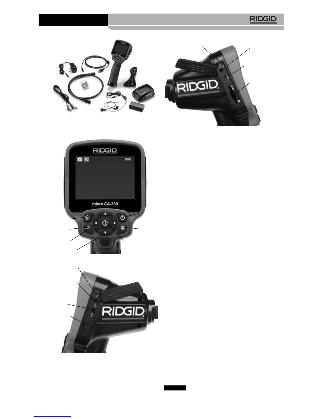
Figure 4 – Left Side Port Cover
FCC Statement
This equipment has been tested and found to
comply with the limits for a Class B digital
device, pursuant to part 15 of the FCC Rules.
These limits are designed to provide reasonable protection against harmful interference in
a residential installation.
This equipment generates, uses, and can radiate radio frequency energy and, if not installed and used in accordance with the instructions, may cause harmful interference
to radio communications.
However, there is no guarantee that interference will not occur in a particular installation.
If this equipment does cause harmful interference to radio or television reception, which
can be determined by turning the equipment
OFF and ON, the user is encouraged to try to
correct the interference by one or more of
the following measures:
• Reorient or relocate the receiving antenna.
• Increase the separation between the equipment and receiver.
• Consult the dealer or an experienced radio/ TV technician for help.
Electromagnetic
Compatibility (EMC)
The term electromagnetic compatibility is
taken to mean the capability of the product to
function smoothly in an environment where
electromagnetic radiation and electrostatic
discharges are present and without causing
electromagnet interference to other equipment.
The RIDGID micro CA-330 Inspect -
ion Camera conforms to all applicable EMC
Figure 1 – micro CA-330 Inspection Camera
Controls
Figure 2 – Controls
Figure 3 – Right Side Port Cover
5
micro CA-330 Inspection Camera
NOTICE
Rotate
Image
Menu
Return
Power
Select/Confirm
Shutter
Arrows
Integrated
Microphone
AC Adapter
Marked
“DC 5V”
Audio
Jack
Speaker
TV-Out
Mini-B USB
SD™ Card
Reset Button
Page 8
Tool Assembly
WARNING
To reduce the risk of serious injury during use, follow these procedures for
proper assembly.
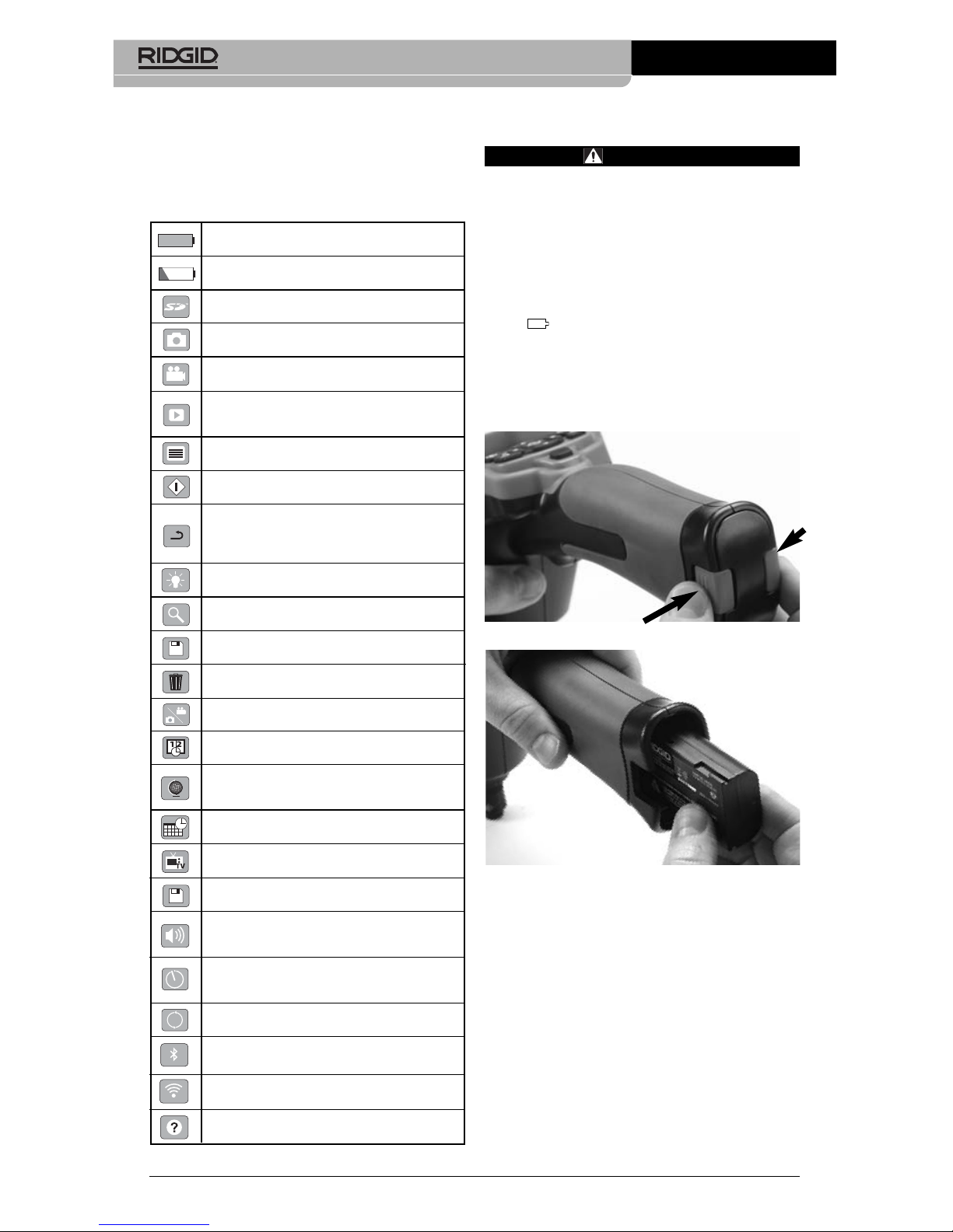
Changing/Installing Batteries
The micro CA-330 is supplied without the
battery installed. If the battery indicator displays , the battery needs to be recharged.
Re move the battery prior to long term storage
to avoid battery leakage.
1. Squeeze the battery clips
(See Figure
5)
and pull to remove battery compart-
ment cover. If needed, slide battery out.
Figure 5 – Battery Compartment Cover
Figure 6 – Removing/Installing Battery
2. Insert contact end of battery into the inspection tool, as shown in
Figure 6
.
3. Replace battery compartment cover.
Powering with the AC Adapter
The micro CA-330 Inspection Camera can al so be powered using the supplied AC Adapter.
1. Open the right side port cover
(Figure 3).
2. Insert the AC adapter barrel plug into
the port marked “DC 5V”.
3. With dry hands, plug the AC adapter into
the outlet.
standards. However, the possibility of it causing interference in other devices cannot be
precluded.
Icons
6
micro CA-330 Inspection Camera
Battery Life Indicator – Fully charged
battery.
Battery Life Indicator – Less than 25%
of battery charge remains.
SD™ Card – Indicates an SD card has
been inserted into the device.
Still Camera – Indicates device is operating in still camera mode.
Video Camera – Indicates device is operating in video camera mode.
Playback Mode – Selecting this icon allows you to view and delete previous ly
saved images and video.
Menu – Push select on this icon to be
taken to the menu screen.
Select – Pressing select from the live
screen will take you to the playback screen.
Return – Pressing return from the live
screen will switch between camera and
video. Return will also back out of menu
and playback mode.
LED Brightness – Press right & left arrows to change the LED brightness.
Zoom – Press up & down arrows to
change the zoom from 1.0x to 2.0x.
Save – Indicates image or video has
been saved to memory.
Trash – Delete confirmation icon.
Mode – Select between image, video or
playback.
Time Stamp – Select to display or hide
date and time on live screen.
Language – Choose between, English,
French, Spanish, German, Dutch, Italian,
etc.
Time and Date – Enter this screen to set
time and date.
TV – Chose between NTSC and PAL to
enable TV out video format.
Update Firmware – Use to update unit
with most current software.
Speaker/Microphone – Turns speaker
and microphone ON or OFF during
recording and playback.
Automatic Power OFF – Device will
automatically shut down after 5, 15 or
60 minutes of inactivity.
Factory Reset – Restore factory defaults.
Bluetooth
®
– Turn ON or OFF ability to
connect to a Bluetooth microphone.
Wi-Fi – Turn ON or OFF Wi-Fi broadcast.
About – Displays software version.
Page 9
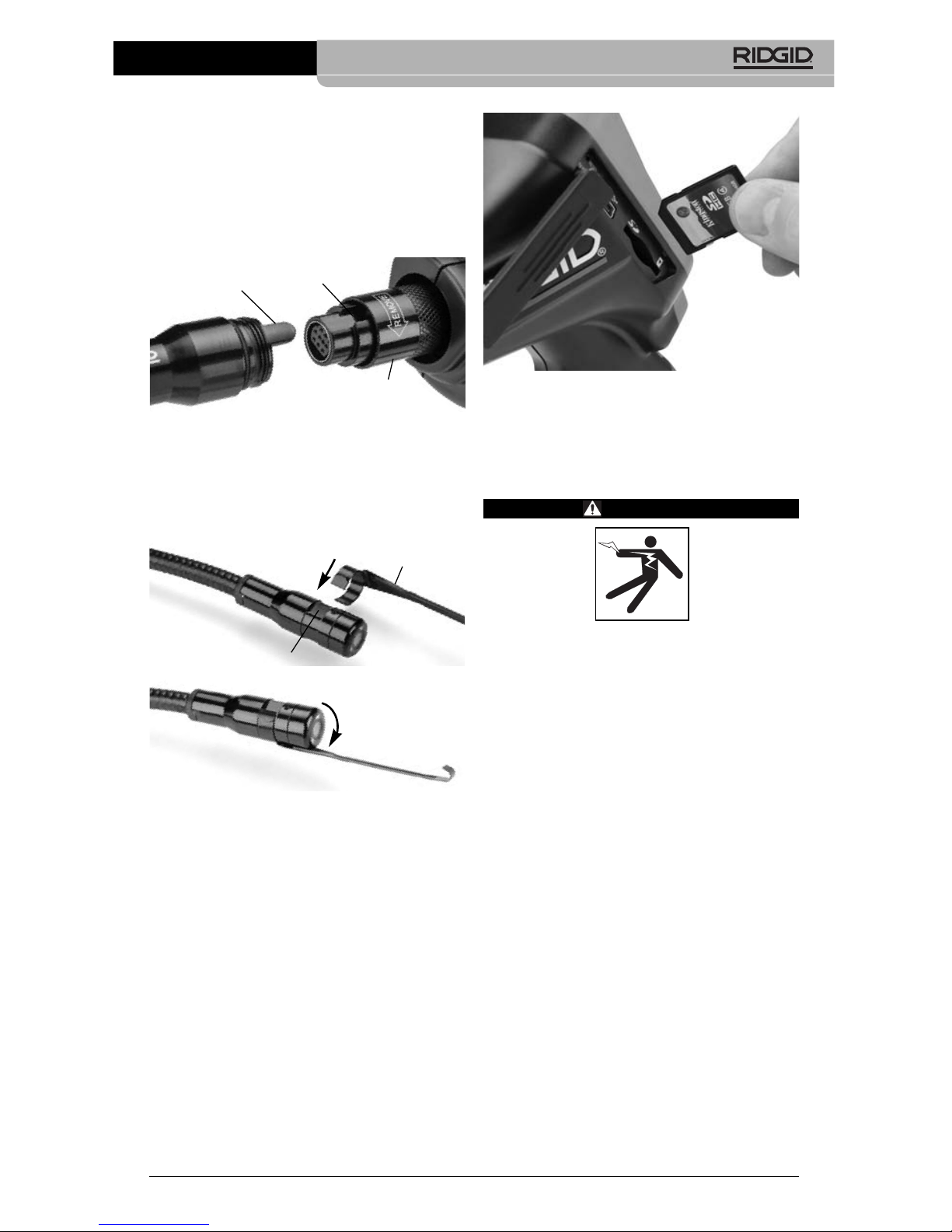
Figure 9 – Inserting the SD Card
Pre-Operation
Inspection
WARNING
Before each use, inspect your Inspec tion Camera and correct any problems
to reduce the risk of serious injury from
electric shock and other causes and
prevent tool damage.
1. Make sure the unit is OFF.
2. Remove the battery and inspect it for
signs of dam age. Re place battery if necessary. Do not use Inspection Camera if
the battery is damaged.
3. Clean any oil, grease or dirt from the e quip ment. This aids inspection and helps
prevent the tool from slipping from your
grip.
4. Inspect micro CA-330 Inspection Camera
for any broken, worn, miss ing or binding parts or any condition which may
prevent safe and normal operation.
5. Inspect the camera head lens for condensation. To avoid damaging the unit, do
not use the camera if condensation forms
inside the lens. Let the water evaporate
before using.
6. Inspect the full length of the cable for
cracks or damage. A damaged cable
could allow water to enter the unit and increase the risk of electrical shock.
Installing the Imager Head
Cable or Extension Cables
To install imager head or extension cables
(see accessory section), align the socket key
with the socket slot and slide the connectorstogether. Secure the connection by tightening the knurled knob
(Figure 7)
.
Figure 7 – Cable Connections
Installing Accessories
The three included accessories, (Hook, Mag net, Mirror) all attach to the imager head the
same way.
Figure 8 – Installing an Accessory
Slip the semicircle end of the accessory over
the flats of the imager head. Then rotate the
accessory a
1
/4turn to retain
(Figure 8)
.
Installing SD™ Card
Open the left side port cover
(Figure 4)
to access the SD card slot. Insert the SD card into
the slot as shown in
Figure 9
. SD cards can
only be installed one way – do not force. When
an SD card is installed, a small SD card icon
will appear in the upper left hand portion of the
screen, along with the number of images or
length of video that can be stored on the SD
card.
Accessory
7
micro CA-330 Inspection Camera
Key
Slot
Knob
1/4 Turn
Flats
Page 10
7. Check to make sure the connections between the handheld unit, extension cables
and imager cable are tight. All connections must be properly assembled for the
cable to be water resistant. Con firm unit is
properly assembled.
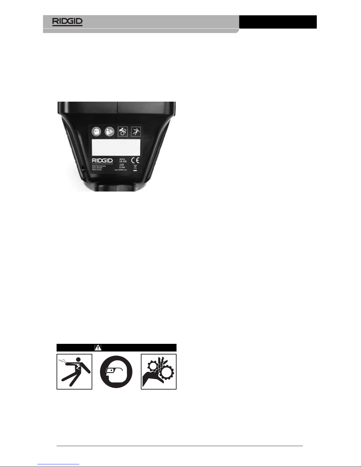
8. Check that the warning label is present,
firmly attached and readable
(Figure 10)
.
Figure 10 – Warning Label
9. If any issues are found during the inspection, do not use the inspection camera until it has been properly serviced.
10. With dry hands, re-install the battery.
11. Press and hold the Power Button for two
seconds. The imager lights should come
on, then a splash screen
(Figure 11)
will
appear. Once the camera is ready, a live
image of what the camera sees is
displayed on the screen. Con sult the
Troubleshooting
section of this manual
if no picture appears.
12. Press and hold the Power Button for two
seconds to turn camera OFF.
Tool and Work Area
Set-Up
WARNING
Set up the micro CA-330 In spec tion Cam era and work area according to these
procedures to reduce the risk of injury
from electrical shock, entanglement and
other causes and prevent tool damage.
micro CA-330 Inspection Camera
8
1. Check work area for:
• Adequate lighting
• Flammable liquids, vapors or dust that
may ignite. If present, do not work in
area until sources have been identified
and corrected. The micro CA-330 In spection Camera is not explosion proof
and can cause sparks.
• Clear, level, stable, dry place for operator. Do not use the inspection camera
while standing in water.
2. Examine the area or space that you will
be inspecting and determine if the micro
CA-330 Inspection Camera is the correct
piece of equipment for the job.
(See
Specifications.)
• Determine if there is any electrical pow -
er supplied to the area to be inspected.
If so, the power to the area must be
turned OFF to reduce the risk of electric
shock. Use appropriate lock out procedures to prevent the power from
being turned back on during the inspection.
• Determine if any liquids will be encoun-
tered during the inspection. The handheld display unit is water resistant
(IP65) but should not be submerged in
water.
• Determine if any chemicals are pres-
ent, especially in the case of drains. It is
important to understand the specific
safety measures required to work a round any chemicals present. Contact
the chemical manufacturer for required
information. Chemicals may damage or
degrade the inspection camera.
• Determine if any moving parts are pres-
ent in the area to be inspected. If so,
these parts must be deactivated to prevent movement during inspection to
reduce the risk of entanglement. Use
appropriate lock out procedures to prevent the parts from moving during the
inspection.
If the micro CA-330 Inspection Camera is not
the correct piece of equipment for the job,
other inspection equipment is available from
RIDGID. For a complete listing of RIDGID
products, see the RIDGID catalog, online at
www.RIDGID.com or www.RIDGID.eu.
Page 11
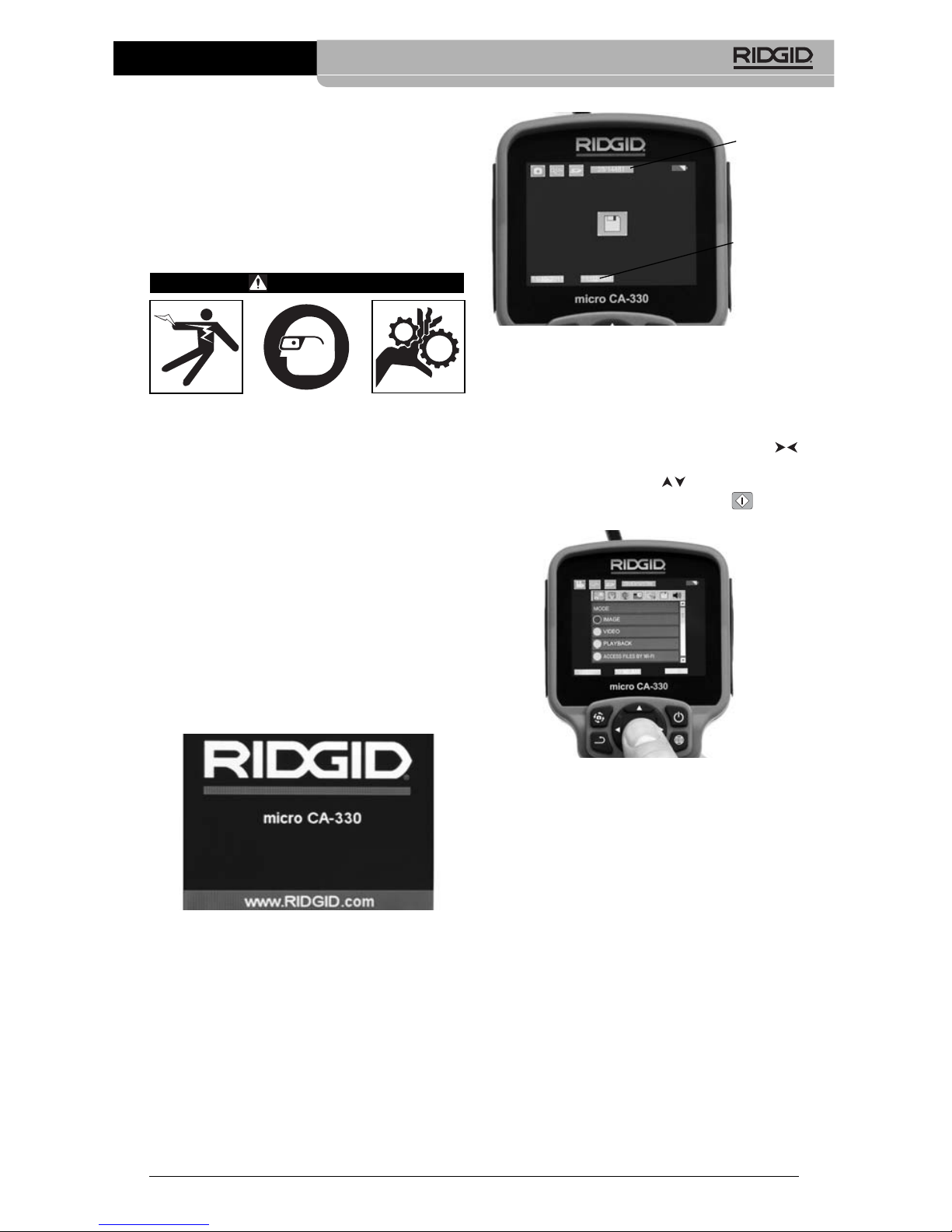
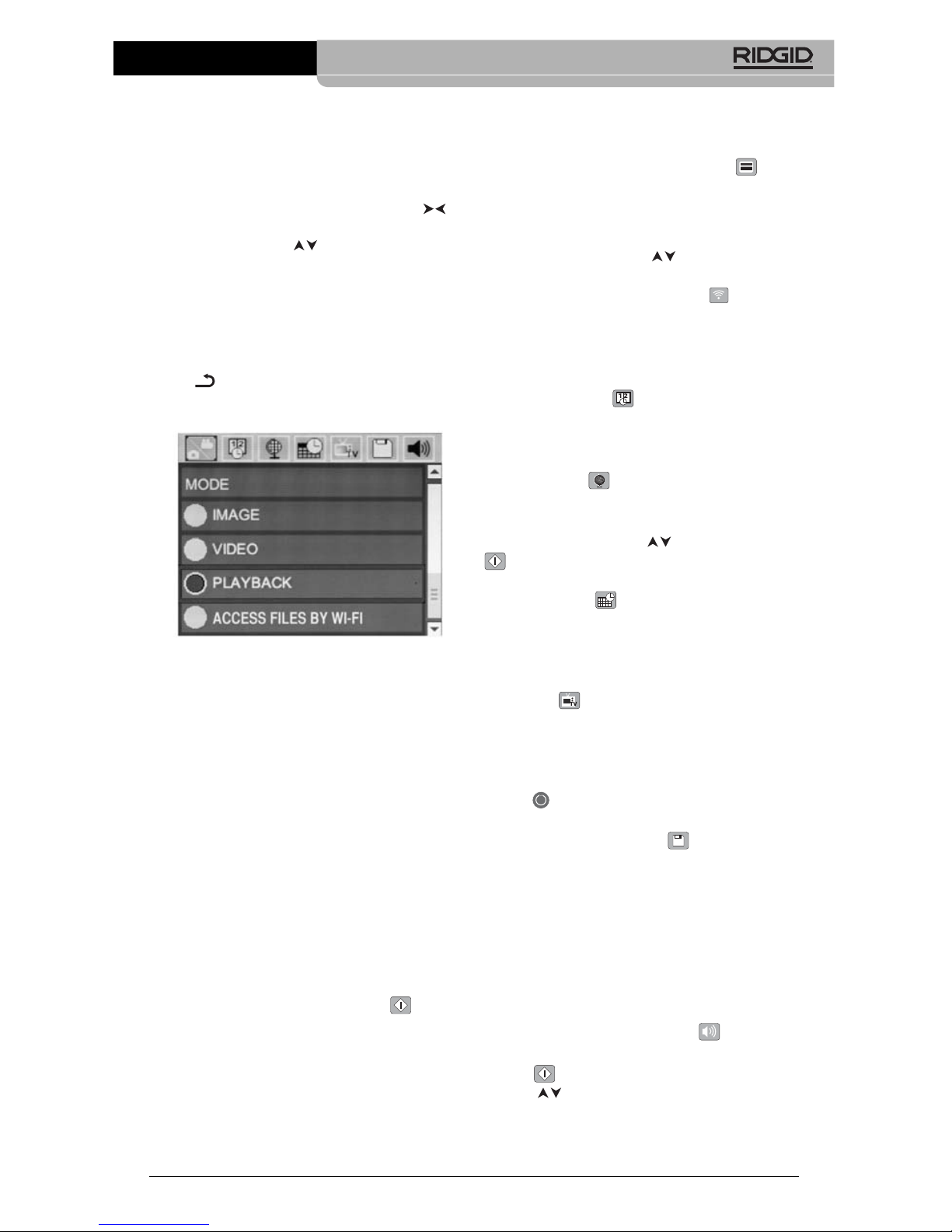
Figure 12 – Live Screen
When the Inspection Camera is turned ON, the
default mode is for capturing still images.
Pressing the menu button at any time will access the menu. The menu will overlay on the
LIVE Screen. Use the right and left arrow
buttons to switch to the MODE category. Use
the up and down arrows to navigate between menu items and press select as desired.
Figure 13 – Screen Shot of Mode Selection
3. If the other inspection camera settings
(Time Stamp, Language, Date/Time, TV
Out, Update Firmware, Speaker/Micro phone, Auto Power OFF, Factory Reset)
need to be adjusted,
see Menu Section.
4. Prepare the camera for inspection. The
camera cable may need to be pre-formed
or bent to properly inspect the area. Do not
try to form bends less than 5" (13 cm)
radius. This can damage cable. If inspecting a dark space, turn the LEDs on before
inserting the camera or cable.
Do not use excessive force to insert or
withdraw the cable. This may result in
damage to the inspection camera or inspection area. Do not use the cable or imager head to modify surroundings, clear
pathways or clogged areas, or as anything other than an inspection device.
3. Make sure the micro CA-330 Inspec tion
Camera has been properly inspect ed
before each use.
4. Install the correct accessories for the application.
Operating Instructions
WARNING
Always wear eye protection to protect
your eyes against dirt and other foreign
objects.
Follow operating instructions to reduce
the risk of injury from electrical shock,
entanglement and other causes.
1. Make sure that the Inspection Camera
and work area have been properly set up
and that the work area is free of bystand ers and other distractions.
2. Press and hold the Power Button for two
seconds. The imager lights should come
ON, then a splash screen
(Figure 11)
will appear. This screen tells you the device is booting up. Once the product is
fully powered up, the screen will automatically switch to the live screen.
Figure 11 – Splash Screen
Live Screen
The live screen is where you will do most of
your work. A live image of what the camera
sees is displayed on the screen. You can
zoom, adjust LED brightness and take images or video from this screen.
The screen has a status bar at the top showing the tool mode, zoom, SD™ card icon if inserted, available memory and speaker/mic
ON/OFF. The information bar at the bottom
shows the date and time if time stamp is ON.
micro CA-330 Inspection Camera
9
Status
Bar
Informa -
tion Bar
Page 12
This may result in damage to the Inspec tion camera or inspection area.
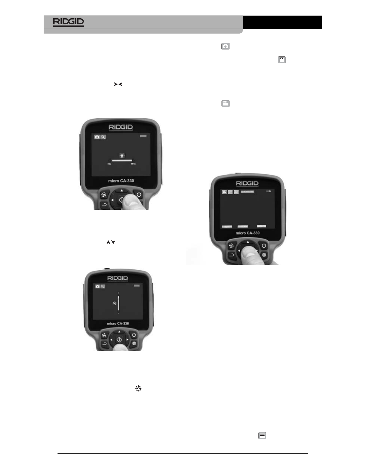
Image Adjustment
Adjust LED Brightness : Pressing the right
and left arrow button on the button pad (In
live screen) will increase or decrease the
LED brightness. A brightness indicator bar
will be displayed on the screen as you adjust
brightness.
Figure 14 – Adjusting LED
Zoom : The micro CA-330 Inspection Camer -
a has a 2.0x digital zoom. Simply press the up
and down arrows while in the live screen
to zoom in or out. A zoom indicator bar will be
displayed on the screen as you adjust your
zoom.
Figure 15 – Adjusting Zoom
Image Rotation : If needed, the image/video
seen on the screen can be rotated in 90 degree increments counter clockwise by pressing the rotate image button .
Image Capture
If an SD card is installed, images will be stored
there. Otherwise, internal memory will be used.
Capturing a Still Image
While in the live screen, make sure the still
micro CA-330 Inspection Camera
10
camera icon is present at the top left portion of the screen. Press the shutter button to
capture the image. The save icon will momentarily appear on the screen. This indicates the still image has been saved.
Capturing a Video
While in the live screen, make sure the video
camera icon is present at the top left portion of the screen. Press the shutter button to
start capturing video. When the device is
recording a video, a red outline will flash
around the video mode icon and the recording
duration will show at the top of the screen.
Press the shutter button again to stop the
video. It may take several seconds to save
the video. The menu cannot be accessed
when recording.
Figure 16 – Video Recording Screen
Audio Recording
When recording video, audio will be recorded
if the microphone is on. Audio can be added
through
• The integrated microphone under the
right side port cover.
• The included headset/microphone. When
plugged into the audio port on the right
side of the camera, this will be used instead of the integrated microphone.
• A Bluetooth microphone.
See “Using a
Bluetooth
®
Microphone” on Page 13.
When
paired with the camera and connected,
this will be the primary microphone.
5. When the inspection is complete, carefully withdraw the camera and cable from
the inspection area.
Menu
Pressing the Menu button at any time will
access the menu. The menu will overlay on the
Page 13
micro CA-330 Inspection Camera
11
LIVE Screen. From the menu, the user will
be able to change to the various modes or
enter the settings menu.
There are different setting categories to choose
from
(Figure 17)
while in the settings screen.
Use the right and left arrow buttons to
switch from one category to the next. Use the
up and down arrows to navigate the menu
items. The selected category will be highlighted with a bright red outline. Once the desired setting is reached, press select to change
to the new selection. The changes are automatically saved when they are changed.
While in menu mode, you can press the Return
button to return to the previous screen or to
the live screen.
Figure 17 – Settings Screen
Mode
Allows selection between Image Capture,
Video Recording, Playback, and Access files
by Wi-Fi.
Image
Selection enables the shutter button to capture
an image.
Video
Selection enables the shutter button to start
and stop the recording of a video.
Playback
Selection allows viewing of images or video.
A shortcut to this menu is available in live
screen mode by pressing Select .
While reviewing an image the user will be
able to cycle through all saved images,
delete an image and display file information.
While reviewing a video, a user will be able to
navigate through videos, pause, restart and
delete. A user will only be able to playback
images and video from internal memory
when SD™ Card is not inserted.
To Delete files, press Menu button while
in playback mode to delete the image or
video. The delete confirmation dialog allows
the user to delete unwanted files. The active
icon is outlined in red. Navigation is done
with the arrow buttons .
Access Files by Wi-Fi
Selection enables the transfer of files by Wi-Fi
to a computer or mobile device.
See Transfer -
ring Files to a Computer by Wi-Fi on Page 12.
Time Stamp
Enable or Disable the display of the Date and
Time.
Language
Select the “Language” icon in the menu and
press Select. Select different languages with
up/down arrow buttons , then press Select
to save the language setting.
Date/Time
Select Set Date or Set Time to set the current
date or time. Select Format Date or Time to
change how the date/time is displayed.
TV-Out
Select the “NTSC” or “PAL” to enable the TVOut for the video format required. Screen will
go black and image will be transmitted to external screen. To get live image on unit, hit Power
button to disable function.
Update Firmware
RIDGID may release updated software to increase features or address a problem. Select
Update Firmware to install the latest version of
software on the unit. Software will have to be
loaded onto a SD™ Card and inserted into
the unit. Software Updates and instructions
can be found online in the support section of
www.RIDGID.com.
Speaker/Microphone
Select the Speaker icon in the menu and press
Select . Select ON or OFF with up/down
button to keep the speaker and microphone ON or OFF during video playback.
Page 14

Auto Power OFF
Select the Auto Power OFF icon and press select . Select disable to turn OFF the auto ma tic shut down function. Select the 5 Minutes,
15 Minutes or 60 Minutes to turn OFF the
tool upon 5/15/60 minutes of non-operation.
Automatic shut down setting will not be activated when recording or playing video.
Factory Reset
Select the Reset icon and press Select .
Confirm the reset function by selecting Yes
and press Select again. This will reset the
tool to the factory default settings.
Bluetooth
®
Select ON or OFF to enable or disable Blue tooth. Select SEARCH and press Select to
search for Bluetooth compatible microphones.
Wi-Fi
Select ON or OFF to enable or disable Wi-Fi
broadcast.
About
Select the About function to display the firm ware revision of the micro CA-330 as well as
the software copyright information.
Transferring Files
Computer with USB
With the unit powered ON, connect the micro
CA-330 to a computer using the USB cable.
The USB connected screen is displayed on the
micro CA-330. The internal memory and SD™
card (if applicable) will appear as separate
drives on the computer and are now accessible as a standard USB storage device. The
copy and delete options are available from
computer operation.
Computer by Wi-Fi
Verify in the CA-330 settings menu that WiFi
broadcast is turned ON. Using your computer,
search for and connect to the “CA-330” Wi-Fi
network. The CA-330 broadcasts an unsecured Wi-Fi network and no password is required. Please consult your computer instruction manual for details on how to connect to a
Wi-Fi network. Verify on your computer that it is
connected to the “CA-330” Wi-Fi network.
Now press the menu button on the CA-330
and select “Access files by Wi-Fi” mode to
micro CA-330 Inspection Camera
12
allow remote file access. If there is an SD
card installed, you will be prompted on the
CA-330 to select SD card or internal memory
for browsing. The CA-330 will now display a
screen indicating it is in “Access files by Wi-Fi”
mode.
From your computer open the default web
browser and type “http://192.168.2.103/dir/”
into the browser address bar. Your browser will
now display a directory listing of the CA-330
files. From here you may access images and
video from the CA-330 internal memory or
SD-Card. Please consult your internet browser
documentation for specific ways to download
and manipulate files.
Wi-Fi Connection to a Mobile Device
The CA-330 will allow file access and remote 2nd screen viewing from a mobile device such as a tablet or smartphone running
iOS
®
or Android®operating systems. You can
find links to download the
RIDGIDview
app at
www.RIDGID.com/CA-330.
Verify in the CA-330 settings menu that Wi-Fi
broadcast is turned ON. Using your mobile
device, search for and connect to the “CA330” Wi-Fi network. The CA-330 broadcasts an
unsecured Wi-Fi network and no password
is required. Please consult your mobile device instruction manual for details on how to
connect to a Wi-Fi network. Verify on your
mobile device that it is connected to the “CA330” Wi-Fi network.
Open the
RIDGIDview
application on your
mobile device. There is a help file within the
app that describes its features and use.
Do not allow use in wireless mode with a separate monitor to distract you from proper CA330 use. Distractions increase the risk of injury.
Connecting to TV
The micro CA-330 Inspection Camera can
be connected to a television or other monitor
for remote viewing or recording through the included RCA cable.
Open the right side port cover
(Figure 3)
.
Insert the RCA cable into the TV-Out jack.
Insert the other end of the cable into the VideoIn jack on the television or monitor. Check to
make sure the video format (NTSC or PAL)
output is set properly. The television or mon-
itor may need to be set to the proper input to
allow viewing. Select the appropriate TV-Out
format using the menu.
Page 15
micro CA-330 Inspection Camera
13
Using a Bluetooth®Microphone
The first time you connect a Bluetooth compatible microphone you will need to “pair” it to
the CA-330. Turn on your microphone and initiate its “pairing” mode. Please consult your microphone’s documentation for specific instructions.
In the CA-330 Bluetooth settings menu, select
SEARCH. Your Bluetooth microphone should
then appear on the screen. Select your microphone and press SELECT on the CA-330.
Once successfully connected, you will see
the symbol next to your device change from
to . Now audio from your Bluetooth microphone will be used when recording video on
the CA-330.
Use with SeeSnake
®
Inspection Equipment
The micro CA-330 Inspection Camera can
also be used with various SeeSnake Inspec tion Equipment and is specifically designed
to be used with the microReel, microDrain™
and the nanoReel Inspection Systems. When
used with these types of equipment, it retains
all of the functionality described in this manual.
The micro CA-330 Inspection Camera can
also be used with other SeeSnake Inspection
Equipment for viewing and recording only.
For use with SeeSnake Inspection Equip ment, the imager head and any cable extensions must be removed. For the microReel,
microDrain™, nanoReel and similar equipment, see the operator’s manual for information on proper connection and use. For other
SeeSnake Inspection Equipment (typically a
reel and monitor), an adapter must be used to
connect the micro CA-330 Inspection Camer a to a Video-Out port on the SeeSnake Inspec tion Equipment. When connected in this manner, the micro CA-330 Inspection Camera will
display the camera view and can be used for
recording.
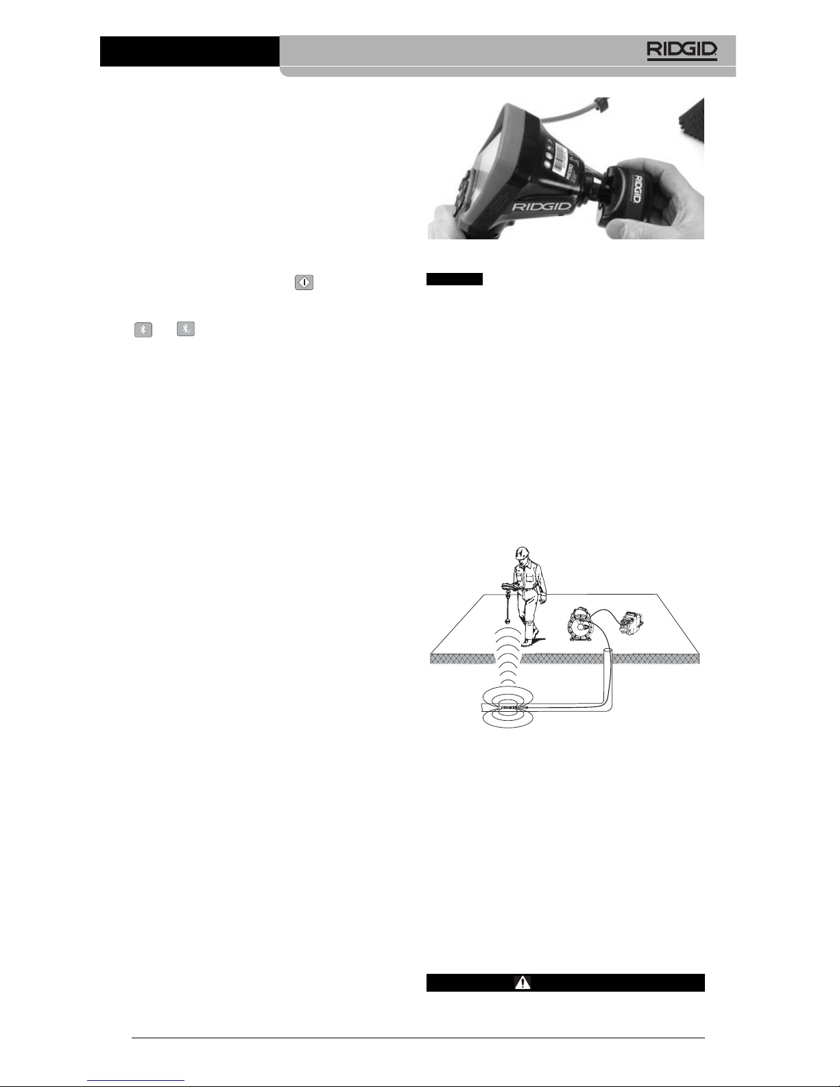
When connecting to SeeSnake Inspection
Equipment (microReel, microDrain™, or nano Reel), align the interconnect module connected to your reel with the cable connector on
the micro CA-330 Inspection Camera, and
slide it straight in, seating it squarely.
(See
Figure 18.)
Figure 18 – Camera Connector Plug Installed
Do not twist the connector plug to
prevent damage.
Locating the Sonde
If used with a sonde (In-Line Transmitter), the
sonde can be controlled two ways. If the reel is
equipped with a sonde key, that can be used to
turn the sonde ON and OFF. Otherwise, the
sonde is turned ON by decreasing LED brightness to zero. Once the Sonde has been located, the LEDs can be returned to their normal brightness level to continue the inspection.
A RIDGID locator such as the SR-20, SR-60,
Scout
®
, or NaviTrack®II set to 512 Hz can be
used to locate features in the drain being inspected.
Figure 19 – Locating the Reel Sonde
To locate the Sonde, turn the locator ON and
set it to Sonde mode. Scan in the direction of
the Sonde's probable location until the locator
detects the Sonde. Once you have detected
the Sonde, use the locator indications to zero
in on its location precisely. For detailed instructions on Sonde locating, consult the Oper ator's Manual for the locator model you are
using.
Maintenance
WARNING
Remove battery before cleaning.
NOTICE
Page 16
• Always clean the imager head and cable
after use with mild soap or mild detergent.
• Gently clean the display screen with a
clean dry cloth. Avoid rubbing too hard.
• Use only alcohol swabs to clean the cable
connections.
• Wipe the hand held display unit down with
a clean, dry cloth.
Reset Function
If the unit stops functioning and does not operate, press the Reset Button
(under the left
side port cover – Figure 4).
The unit may re-
cover to normal operation when re started.
Accessories
WARNING
To reduce the risk of serious injury, only
use accessories specifically designed
and recommended for use with the
RIDGID micro CA-330 Inspection Camera
such as those listed below. Other Ac ces sories suitable for use with other tools
may be hazardous when used with the
micro CA-330 Inspection Camera.
Further information on accessories speci fic
to this tool can be found in the RIDGID
Catalog and online at www.RIDGID.com or
www.RIDGID.eu.
Storage
The RIDGID micro CA-330 Inspection Cam era must be stored in a dry secure area between -4°F (-20°C) and 158°F (70°C) and
humidity between 15% and 85% RH.
Store the tool in a locked area, out of the
micro CA-330 Inspection Camera
14
reach of children and people unfamiliar with
the micro CA-330 Inspection Cam era.
Remove the battery before any long period of
storage or shipping to avoid battery leakage.
Service and Repair
WARNING
Improper service or repair can make the
RIDGID micro CA-330 Inspection Camera
unsafe to operate.
Service and repair of the micro CA-330 In spec tion Camera must be performed by a
RIDGID In dependent Service Center.
For information on your nearest RIDGID In depen dent Service Center or any service or
repair questions:
• Contact your local RIDGID distributor.
• Visit www.RIDGID.com or www.RIDGID.eu
to find your local RIDGID contact point.
• Contact Ridge Tool Technical Service De partment at rtctechservices@emerson.com,
or in the U.S. and Canada call (800) 519-
3456.
Disposal
Parts of the RIDGID micro CA-330 Inspection
Camera contain valuable materials and can be
recycled. There are companies that specialize
in recycling that may be found locally. Dispose
of the com ponents in compliance with all applicable regulations. Contact your local waste
management authority for more information.
For EC Countries: Do not dispose
of elec trical equipment with household waste!
According to the European Guide line 2012/ 19/EC for Waste Elec -
trical and Electronic Equipment
and its imple men tation into national legislation,
electrical equipment that is no longer usable
must be collected separately and disposed of
in an environmentally correct manner.
micro CA-330 Inspection Camera
Accessories
Catalog
No. Description
37108 3' (90 cm) Cable Extension
37113 6' (180 cm) Cable Extension
37103 Imager Head and Cable - 17 mm
37098 1m length 6mm diameter imager
37093 4m length 6mm diameter imager
37123 17mm Accessory Pack (Hook,
Magnet, Mirror)
40028 AC Adapter
40623 Headset Accessory with
Microphone
Page 17

micro CA-330 Inspection Camera
15
SYMPTOM POSSIBLE REASON SOLUTION
Display turns ON, but
does not show image.
LEDs on imager head
are dim at max brightness, display switches
between black and
white, color display
turns itself OFF after a
brief period.
Unit will not turn ON.
Troubleshooting
Loose cable connections.
Imager is broken.
Imager head covered by debris.
Battery low on power.
Dead battery.
Unit need to be reset.
Check cable connections, clean if required. Re-attach.
Replace the Imager.
Visually inspect imager head to make
certain it is not covered by debris.
Replace battery with charged battery.
Replace with charged battery.
Reset unit.
See “Maintenance” Section.
Page 18

micro CA-330 Inspection Camera
16
Battery Pack/Battery
Charger Safety
WARNING
To reduce the risk of serious injury, read
these precautions carefully before using
the battery charger or battery
Battery Charger Safety
• Charge only the RIDGID rechargeable
battery listed in the Accessories Sec tion with the RIDGID Battery Charger.
Other types of batteries may burst causing
personal injury and property damage.
• Do not probe battery charger with con-
ductive objects. Shorting of battery terminals may cause sparks, burns or electrical
shock.
• Do not insert battery into charger if
charger has been dropped or damaged
in any way. A damaged charger increases
the risk of electrical shock.
• Charge battery in temperatures above
32°F (0°C) and below 122°F (50°C). Store
charger in temperatures above -4°F (-20°C)
and below 104°F (40°C). Storage for a long
time at temperatures above 104°F (40°C)
can reduce the capacity of the battery.
Proper care will prevent serious damage to
the battery. Improper care of the battery
may result in battery leakage, electrical
shock and burns.
• Use an appropriate power source. Do
not attempt to use a step-up transformer or
an engine generator, doing so may cause
damage to the charger resulting in electrical shock, fire or burns.
• Do not allow anything to cover the
charg er while in use. Proper ventilation is
required for correct operation of the
charger. Allow a minimum of 4" (10 cm) of
clearance around the charger for proper
ventilation.
• Unplug the charger when not in use.
This reduces the risk of injury to children
and untrained persons.
• Unplug the charger from outlet before
attempting any maintenance or cleaning. Reduces the risk of electrical shock.
• Do not charge battery in damp, wet or
explosive environment. Do not expose to
rain, snow or dirt. Contaminants and moisture increase the risk of electrical shock.
• Do not open the charger housing. Have
repairs performed only at authorized locations.
• Do not carry charger by power cord.
Reduces the risk of electrical shock.
• The RIDGID Battery Charger is not intend ed for use by persons (including children)
with reduced physical, sensory or mental
capabilities, or lack of experience and
knowledge, unless they have been given
supervision or instruction concerning use
of the RIDGID Battery Charger by a person responsible for their safety.
• Keep children and by-standers away
while operating equipment. Distractions
can cause you to lose control.
• Have your equipment (including power
supply cord) serviced by a qualified repair person using only identical replacement parts. If the equipment is damaged, it must be replaced by the manufacturer, its service agent or similarly
qualified persons in order to avoid a
hazard. This will ensure that the safety of
the tool is maintained.
Battery Safety
• Properly dispose of the battery. Ex po -
sure to high temperatures can cause the
battery to explode, so do not dispose of in
a fire. Place tape over the terminals to
prevent direct contact with other objects.
Some countries have regulations concerning battery disposal. Please follow all applicable regulations. Also,
refer to Disposal
section.
• Do not insert the battery with cracked
case into charger. Damaged batteries increase the risk of electrical shock.
• Never disassemble battery. There are
no user-serviceable parts inside the battery. Disassembling batteries may cause
electrical shock or personal injury.
• Avoid contact with fluids oozing from
damaged batteries. Fluids may cause
burns or skin irritation. Thoroughly rinse
with water in case of accidental contact
with fluid. Consult doctor if fluid comes
into contact with eyes.
Page 19
micro CA-330 Inspection Camera
17
Description and
Specifications
Description
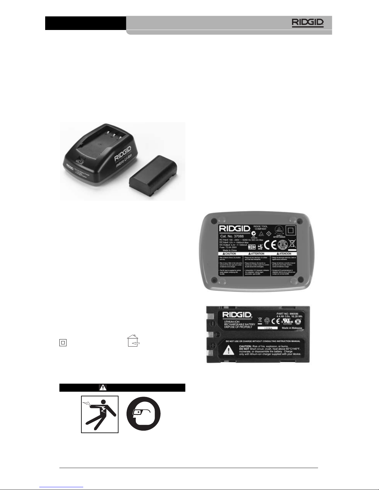
The RIDGID Battery Charger (Catalog Num ber 37088), when used with appropriate batteries (Catalog Number 37083) listed in the
Accessories
section, is designed to charge the
Li-Ion RIDGID battery in approximately 4-5
hours. This charger requires no adjustments.
Figure 20 – Battery and Charger
Specifications
Input ............................100-240 VAC,
50/60 Hz
Output..........................4.2 V DC
Battery Type ................3.6V or 3.7 V Li-Ion
Battery Capacity..........4.2Ah
Input Current ...............0.3A (AC) / 1A (DC)
Weight .........................0.4 lbs (0,02 kg)
Charging Time.............4 to 5 Hrs
Cooling ........................Passive Convection
Cooling (No Fan)
Icons
Double Insulated
Charger Inspection and
Set-Up
WARNING
Before use, inspect the charger and batteries and correct any problems. Set up
charger according to these procedures
to reduce the risk of injury from electri-
cal shock, fire, and other causes and
prevent tool and system damage. Always
wear eye protection to protect your eyes
against dirt and other foreign objects.
1. Make sure the charger is unplugged.
Inspect the power cord, charger and battery for damage or modifications, or broken, worn, missing, misaligned or binding
parts. If any problems are found, do not
use charger until the parts have been
repaired or replaced.
2. Clean any oil, grease or dirt from the
equipment as described in the
Cleaning
Instructions
section, especially handles
and controls. This helps prevent the
equip ment from slipping from your grip
and allows proper ventilation.
3. Check to see that all warning labels and
decals on the charger and battery are
intact and readable.
(See Figures 21 &
22.)
Figure 21 – Label on Charger
Figure 22 – Label on Battery
4. Select an appropriate location for the
charger before use. Check work area for:
• Adequate lighting.
• Clear, level, stable, dry place for charg -
er. Do not use the device in wet or
damp areas.
• Proper operating temperature range.
The charger and battery must both be
between 32°F (0°C) and 122°F (50°C)
for charging to begin. If the temperature
For Indoor
Use Only
Page 20
micro CA-330 Inspection Camera
18
of either is outside of this range at any
point during charging, the operation will
be suspended until brought back to the
correct temperature range.
• Appropriate power source. Check to
see that the plug fits correctly into the
desired outlet.
• Sufficient ventilation. The charger needs
a clearance of at least 4" (10 cm) on all
sides to maintain a proper operating
temperature.
5. Plug cord into charger.
6. With dry hands, plug charger into the
appro priate power source.
Charging
Procedure/Operating
Instructions
WARNING
Always wear eye protection to protect
your eyes against dirt and other foreign
objects.
Follow operating instructions to reduce
the risk of injury from electrical shock.
NOTE! New batteries reach their full capacity
after approximately 5 charging and discharging cycles.
1. Set up charger according to the
Charger
Inspection and Set-Up
section.
2. The charger conducts a 1-second life
test during which the LED blinks from
red to green. The charger then goes into
standby mode in which the LED is OFF.
3. With dry hands, insert the battery pack
onto the charger. The battery pack will
begin charging automatically. While the
battery is charging, the red LED will glow
solid.
4. When the battery is fully charged, the
green LED glows solid. Remove the battery. Once the battery is charged, it may
remain on the charger until it is ready to
be used. There is no risk of over-charging
the battery. When the battery has been
fully charged, the charger automatically
switches to retention charging.
5. With dry hands, unplug the charger from
the outlet once charging is complete.
Cleaning Instructions
WARNING
Unplug the charger before cleaning. Do
not use any water or chemicals to clean
charger or batteries to reduce the risk of
electrical shock.
1. If present, remove battery from charger.
2. Remove any dirt or grease from the ex terior of the charger and battery with a
cloth or soft non-metallic brush.
Accessories
WARNING
To reduce the risk of serious injury, only
use accessories specifically designed
and recommended for use with the
RIDGID Li-Ion Battery Charger such as
those listed below. Other Accessories
suitable for use with other tools may
be hazardous when used with the
RIDGID Li-Ion Battery Charger.
Further information on accessories specific
to the charger can be found in the RIDGID
Catalog and online at www.RIDGID.com or
www.RIDGID.eu.
Storage
Store the charger and the batteries in a dry,
secured, locked area that is out of reach of
children and people not familiar with proper
charger operation.
The batteries and charger should be protected
against hard impacts, moisture and humidity,
dust and dirt, extreme high and low temperatures and chemical solutions and vapors.
Long-term storage in temperatures
above 104°F (40°C) can permanently reduce
the capacity of the batteries.
Catalog
No. Description
37088 micro CA-330 Charger
37083 micro CA-330 3.6V Li-Ion Battery
NOTICE
Page 21

micro CA-330 Inspection Camera
19
Service and Repair
WARNING
Improper service or repair can make the
RIDGID micro CA-330 Inspection Camera
unsafe to operate.
There are no user-serviceable parts for this
charger or batteries. Do not attempt to open
charger or battery cases, charge individual
battery cells or clean internal components.
Service and repair of the charger must be
performed by a RIDGID Independent Service
Center.
For information on your nearest RIDGID In depen dent Service Center or any service or
repair questions:
• Contact your local RIDGID distributor.
• Visit www.RIDGID.com or www.RIDGID.eu
to find your local RIDGID contact point.
• Contact Ridge Tool Technical Service De partment at rtctechservices@emerson.com,
or in the U.S. and Canada call (800) 519-
3456.
Battery Disposal
For USA and Canada: The
RBRC™ (Rechargeable Battery
Recycling Corporation) Seal on
the battery packs means that
RIDGID has already paid the
cost of recycling the lithium-ion battery packs
once they have reached the end of their useful
life.
RBRC™, RIDGID
®
, and other battery suppliers have developed programs in the USA
and Canada to collect and recycle rechargeable batteries. Normal and rechargeable batteries contain materials that should not be
directly disposed of in nature, and contain
valuable materials that can be recycled. Help
to protect the environment and conserve natural resources by returning your used batteries to your local retailer or an independent
RIDGID service center for recycling. Your local
recycling center can also provide you with
additional drop off locations.
RBRC™ is a registered trademark of the
Rechargeable Battery Recycling Corporation.
For EC countries: Defective or used battery
packs/bat teries must be recycled according to
the guideline 2006/66/EEC.
Page 22

micro CA-330 Inspection Camera
20
Page 23

Caméra d’inspection
micro CA-330
micro CA-330
Caméra d’inspection micro CA-330
Notez ci-dessous et conservez le numéro de série indiqué sur la plaque signalétique de
l’appareil.
N° de
série
AVERTISSEMENT
Familiarisez-vous avec ce mode
d’emploi avant d’utiliser l’appareil.
L’incompréhension ou le non respect
des consignes ci-devant augmenterait
les risques de choc électriques,
d’incendie et/ou de graves lésions
corporelles.
Page 24

22
Caméra d’inspection micro CA-330
Table des matières
Symboles de sécurité..................................................................................................................21
Consignes générales de sécurité
Sécurité des lieux .....................................................................................................................23
Sécurité électrique....................................................................................................................23
Sécurité individuelle..................................................................................................................23
Utilisation et entretien du matériel ............................................................................................24
Service après-vente..................................................................................................................24
Consignes de sécurité particulières
Sécurité de la caméra d’inspection micro CA-330....................................................................24
Description, caractéristiques techniques et équipements de base
Description................................................................................................................................25
Caractéristiques techniques .....................................................................................................25
Equipements de base...............................................................................................................26
Commandes .............................................................................................................................26
Enoncé de la FCC ........................................................................................................................27
Compatibilité électromagnétique (EMC)....................................................................................27
Icônes............................................................................................................................................27
Assemblage de l’appareil
Installation et remplacement des piles......................................................................................28
Alimentation sur secteur à l’aide du transformateur .................................................................28
Installation du câble de tête de caméra et de ses rallonges.....................................................28
Montage des accessoires.........................................................................................................28
Insertion de la carte SDTM.........................................................................................................28
Contrôle préalable de l’appareil..................................................................................................29
Préparation de l’appareil et des lieux ........................................................................................30
Consignes d’utilisation ...............................................................................................................30
Ecran virtuel..............................................................................................................................31
Réglage de l’image...................................................................................................................31
Capture d’image .......................................................................................................................32
Enregistrement audio................................................................................................................32
Menu.........................................................................................................................................32
Mode.........................................................................................................................................33
Accès aux fichiers via Wi-Fi......................................................................................................33
Vignette horaire ........................................................................................................................33
Langue......................................................................................................................................33
Date et heure............................................................................................................................33
Sortie télé .................................................................................................................................33
Mise à jour logiciel ....................................................................................................................33
Haut Parleur/Microphone..........................................................................................................33
Arrêt automatique .....................................................................................................................34
Retour aux paramètres d’origine ..............................................................................................34
Bluetooth®.................................................................................................................................34
Wi-Fi .........................................................................................................................................34
A propos ...................................................................................................................................34
Transfert des fichiers.................................................................................................................34
Connexion télé..........................................................................................................................35
Utilisation d’un microphone Bluetooth®.....................................................................................35
Utilisation du matériel d’inspection SeeSnake®................................................................................35
Entretien
Réarmement.............................................................................................................................36
Accessoires..................................................................................................................................36
Stockage.......................................................................................................................................36
Service après-vente.....................................................................................................................37
Recyclage .....................................................................................................................................37
Dépannage....................................................................................................................................38
Sécurité des bloc-piles et du chargeur......................................................................................39
Description et caractéristiques techniques ..............................................................................40
Contrôle et installation du chargeur ..........................................................................................40
Utilisation du chargeur................................................................................................................41
Consignes de nettoyage..............................................................................................................41
Accessoires..................................................................................................................................42
Stockage.......................................................................................................................................42
Service après-vente.....................................................................................................................42
Recyclage .....................................................................................................................................42
Garantie à vie............................................................................................................Page de garde
*Traduction de la notice originale
Page 25

Caméra d’inspection micro CA-330
23
Symboles de sécurité
Des symboles et mots clés spécifiques, utilisés à la fois dans ce mode d’emploi et sur l’appareil
lui-même, servent à signaler d’importants risques de sécurité. Ce qui suit permettra de mieux
comprendre la signification de ces mots clés et symboles.
Ce symbole sert à vous avertir aux dangers physiques potentiels. Le respect des consignes qui
le suivent vous permettra d’éviter les risques de blessures graves ou mortelles.
Le terme DANGER signifie une situation dangereuse potentielle qui, faute d’être
évitée, provoquerait la mort ou de graves blessures corporelles.
Le terme AVERTISSEMENT signifie une situation dangereuse potentielle
qui, faute d’être évitée, serait susceptible d’entraîner la mort ou de graves
blessures corporelles.
Le terme ATTENTION signifie une situation dangereuse potentielle qui, faute d’être
évitée, serait susceptible d’entraîner des blessures corporelles légères ou modérées.
Le terme AVIS IMPORTANT signifie des informations concernant la protection des
biens.
Ce symbole indique la nécessité de lire le manuel soigneusement avant d’utiliser le matériel.
Le mode d’emploi renferme d’importantes informations concernant la sécurité d’utilisation du
matériel.
Ce symbole indique le port obligatoire de lunettes de sécurité intégrales lors de la manipulation ou utilisation du matériel.
Ce symbole indique un risque d’écrasement des doigts ou des mains par les mécanismes
de l’appareil.
Ce symbole indique un risque de choc électrique.
Sécurité électrique
• Evitez tout contact avec les objets reliés
à la terre tels que canalisations, radiateurs, cuisinières et réfrigérateurs. Tout
contact avec la terre augmenterait les
risques de choc électrique.
• N’exposez pas l’appareil à la pluie ou
aux intempéries. Toute pénétration d’eau
à l’intérieur d’un appareil électrique augmenterait les risques de choc électrique.
Sécurité individuelle
• Soyez attentif, faites attention à ce que
vous faites et faites preuve de bon
sens. N’utilisez pas d’appareil électrique
lorsque vous êtes sous l’influence de
drogues, de l’alcool ou de médicaments.
Lors de l’utilisation d’un appareil électrique,
un instant d’inattention risque d’entraîner
de graves lésions corporelles.
• Ne vous mettez pas en porte-à-faux.
Maintenez une bonne position de travail
et un bon équilibre à tout moment. Cela
vous permettra de mieux contrôler l’ap pareil en cas d’imprévu.
• Prévoyez les équipements de protec-
tion individuelle nécessaires. Portez systématiquement une protection oculaire. Le
Consignes générales de
sécurité
AVERTISSEMENT
Familiarisez-vous avec l’ensemble du
mode d’emploi. Le non-respect des consignes d’utilisation et de sécurité ciaprès augmenterait les risques de choc
électrique, d’incendie et/ou de grave
blessure corporelle.
CONSERVEZ CES INSTRUCTIONS !
Sécurité du chantier
• Assurez-vous de la propreté et du bon
éclairage des lieux. Les zones encom-
brées ou mal éclairées sont une invitation
aux accidents.
• N’utilisez pas d’appareils électriques
en présence de matières explosives
telles que liquides, gaz ou poussières
combustibles. Les appareils électriques
produisent des étincelles susceptibles
d’enflammer les poussières et émanations
combustibles.
• Eloignez les enfants et les spectateurs
lors de l’utilisation d’un appareil électrique. Les distractions risquent de vous
faire perdre le contrôle de l’appareil.
AVIS IMPORTANT
DANGER
AVERTISSEMENT
ATTENTION
Page 26

24
Révisions
• Confiez toute révision éventuelle de ce
matériel à un réparateur qualifié garantissant l’utilisation exclusive de pièces
de rechange identiques aux pièces
d’ori gine. Cela assurera la sécurité de
l’appareil.
Consignes de sécurité
spécifiques
AVERTISSEMENT
La section suivante contient d’im por tan tes consignes de sécurité qui s’ad ressent spécifiquement à la caméra
d’inspection.
Afin de limiter les risques de choc électrique ou autres blessures graves, lisez
le mode d’emploi soigneusement avant
d’utiliser la caméra d’inspection micro
CA-330.
CONSERVEZ CES INSTRUCTIONS !
La mallette de transport de la caméra d’in spection micro CA-330 est équipée d’un
porte-documents permettant de garder le
mode d’emploi de l’appareil à portée de
main de tout utilisateur éventuel.
Sécurité de la caméra
d’inspection micro CA-330
• Ne pas exposer l’appareil à l’eau ou
aux intempéries. Cela augmenterait les
risques de choc électrique. La tête de
caméra et son câble sont étanches jusqu’à
une profondeur. L’ap pareil lui-même ne
l’est pas.
• Ne jamais introduire la caméra d’in -
spection micro CA-330 dans un endroit
qui risque de contenir des éléments
sous tension. Cela augmenterait les ris -
ques de choc électrique.
• Ne jamais introduire la caméra d’in -
spection micro CA-330 dans un endroit
qui risque de renfermer un mécanisme
quelconque. Cela augmenterait les risques
de blessure par entraînement.
• Ne pas utiliser cet appareil pour des
diagnostiques personnels ou médicaux
quelconques. Ceci n’étant pas un ap-
pareil médical, de telles utilisations pourraient s’avérer dangereuses.
• Prévoyez systématiquement les équipe -
ments de protection individuelle appro-
port d’un masque à poussière, de chaussures de sécurité antidérapantes, d’un
casque de chantier ou de protecteurs
d’oreilles s’impose lorsque les conditions
l’exigent.
Utilisation et entretien du
matériel
• Ne forcez pas l’appareil. Prévoyez l’ap pareil approprié en fonction des travaux
envisagés. L’appareil approprié fera le tra-
vail plus efficacement et avec un plus
grand niveau de sécurité lorsqu’il tourne au
régime prévu.
• N’utilisez pas d’appareil électrique dont
l’interrupteur ne contrôle pas la mise en
marche ou l’arrêt. Tout appareil électrique
qui ne peut pas être contrôlé par son interrupteur est dangereux et doit être réparé.
• Retirez les piles avant tout réglage, rem-
placement d’accessoires ou stockage
de l’appareil. De telles mesures préventives
limiteront les risques d’accident.
• Rangez tout appareil non utilisé hors de
la portée des enfants et des individus
qui n’ont pas été familiarisés avec ce
type de matériel ou son mode d’emploi.
Les appareils électriques sont dangereux
entre les mains d’utilisateurs non initiés.
• Veillez à l’entretien de l’appareil. Ex -
aminez-le pour signes de grippage, de
bris et de toute autre anomalie qui risquerait de nuire à son bon fonctionnement. Le cas échéant, faire réparer
l’appareil avant de l’utiliser. De nom-
breux accidents sont provoqués par des
appareils mal entretenus.
• Lors de l’utilisation de cet appareil et de
ses accessoires, respectez le mode
d’em ploi ci-présent en tenant compte
des conditions de travail existantes. L’uti -
lisation de cet appareil à des fins autres
que celles prévues pourrait créer des situations dangereuses.
• N’utilisez que les accessoires spéci-
fiquement désignés par le fabricant pour
votre type d’appareil. L’emploi d’ac ces -
soires prévus pour d’autres types d’appareil
augmenterait les risques d’accident grave.
• Assurez-vous de la parfaite propreté
des poignées de l’appareil. Cela assurera une meilleure prise en main.
Caméra d’inspection micro CA-330
Page 27

Caméra d’inspection micro CA-330
25
Description, caractéristiques techniques et
équipements de base
Description
La caméra d’inspection numérique RIDGID
®
micro CA-330 est un puissant appareil d’ins pection vidéo portatif. Cette plate-forme entièrement numérique vous permet d’effectuer
et d’enregistrer les inspections en format photo
ou vidéo dans les endroits difficilement accessibles. Plusieurs possibilités de manipulation d’image (rotation d’image, zoom nu mé rique, etc.) sont incorporées au système pour
assurer des images à la fois détaillées et précises. L’appareil dispose également d’une mémoire externe et d’une sortie télé. Des accessoires de tête de caméra (miroir, crochet et
aimant) sont inclus pour augmenter la souplesse du système.
La caméra est équipée Bluetooth
®
pour l’utili sation de microphones sans fils, et dispose
d’une capacité Wi-Fi pour la visualisation et le
transfert de données à distance.
Caractéristiques techniques
Application
recommandée .............Utilisation à l’intérieur
Distance visuelle .........de 0.4" (10 mm) à
l’infini
Affichage .....................TFT couleur (résolu-
tion : 320 x 240) de
3.5" (90 mm)
ø tête de caméra .........3/4" (17mm)
Eclairage .....................4 LED réglables
Longueur de câble.......3' (0,90 m), jusqu’à
30' avec rallonges,
tête de caméra et
câble étanches
jusqu’à 3.3' (1 m),
IP67
Rayon de courbure mini
du câble.......................5" (13 cm)
Format photo...............JPEG
Résolution d’image......640 x 480
Format vidéo ...............MP4
Résolution vidéo..........320 x 240
Vitesse d’image...........jusqu’à 30 im-
ages/seconde
zoom numérique..........2X
priés lors de la manipulation et l’uti lisation de la caméra d’inspection micro
CA-330. Les canalisations d’évacuation et
autres lieux d’inspection risquent de renfermer des produits chimiques, des bactéries
ou autres substances potentiellement toxiques, infectieuses, irritantes ou autrement
dangereuses. Les équipe-ments de pro-
tection individuelle appropriés comprennent systématiquement les lunettes
et gants de sécurité, voire éventuelle-
ment des équipements supplémentaires
tels que gants en latex ou caoutchouc,
visières intégrales, lunettes fermées, vêtements de protection, appareils respiratoires ou chaussures de sécurité blindées.
• Respectez les consignes d’hygiène.
Suite à toute manipulation ou utilisation de
la caméra d’inspection micro CA-330 dans
des conduites ou autres endroits susceptibles de renfermer des produits chimiques
ou des bactéries, lavez vos mains ou autres
parties du corps éven tuellement exposées
avec de l’eau chaude savonneuse. Ne pas
manger ou fumer lors de la manipulation ou
utilisation de la ca mé ra d’inspection micro
CA-330. Cela aidera à éviter les risques de
contamination par contact avec des substances toxiques ou infectieuses.
• Ne jamais utiliser la caméra d’in spec -
tion micro CA-330 lorsque vous avez
les pieds dans l’eau. L’utilisation d’un ap-
pareil électrique avec les pieds dans l’eau
augmenterait les risques de choc électrique.
• Ne pas permettre l’utilisation de l’ap pa -
reil en mode « sans fils » avec un moni teur indépendant afin de ne pas vous
laisser distraire du fonctionne ment normal de la CA-330. La moindre distraction
peut augmenter les risques d’accident.
Au besoin, le présent manuel sera accompagné de la Déclaration de conformité CE
(890-011-320.10) sous forme de livret individuel.
En cas de questions visant ce produit
RIDGID
®
:
– Consultez votre distributeur RIDGID.
– Visitez le site www.RIDGID.com ou
www.RIDGID.eu pour localiser
l’interlocuteur le plus proche.
– Consultez les services techniques de
Ridge Tool par mail adressé à rtctechservices@emerson.com ou en composant
le (800) 519-3456 (à partir des Etats-Unis
et du Canada exclusivement).
Page 28

26
Commandes
Figure 2 – Commandes
Figure 3 – Branchements côté droit
Figure 4 – Branchements côté gauche
Niveau d’étanchéité de
l’appareil portable........IP65
Sortie télé ....................PAL ou NTSC au
choix
Mémoire interne ..........235 MB
Mémoire externe .........Carte SD
TM
de 32 GB
maxi (4 GB fournie)
Sortie données ............Câble USB, carte
SD™ et Wi-Fi
Portée Bluetooth............16.4' (5 m)
Portée Wi-Fi ................33' (10 m)
Température de
fonctionnement............de 32 à 113 °F
(0 à 45 °C)
Température de
stockage......................de –4 à 140 °F
(-20 à 60 °C)
Alimentation..................Bloc-piles Li-Ion ou
tranformateur CA de
5V/1,5A
Poids.............................5.5 lbs (2,5 kg)
Équipements de base
La caméra d’inspection micro CA-330 est
livrée avec les éléments suivants :
• Appareil portable micro CA-330
• Tête de caméra Ø 17 mm
• Câble USB de 3' (90 cm)
• Câble RCA (avec audio) de 3' (90 cm)
• Crochet, aiment et miroir accessoires
• Bloc-piles Li-Ion
• Chargeur Li-ion avec cordon d’alimentation
• Transformateur
• Casque d’écoute avec microphone
• Carte SD
TM
de 4 GB
• Mode d’emploi
Figure 1 – Caméra d’inspection micro CA-330
Rotation
d’image
Menu
Retour
Marche/
Arrêt
Sélection/
Confirmation
Obturateur
Flèches
Caméra d’inspection micro CA-330
Sortie télé
Mini USB
Carte SD
TM
Remise à zéro
Micro
incorporé
Adaptateur
CA marqué
« DC 5V »
Fiche
casque
Haut-
parleur
Page 29

Caméra d’inspection micro CA-330
27
Icônes
Avertissement FCC
Cet appareil a été testé et homologué au titre
des limites établies pour les dispositifs numé riques Catégorie B sous l’article 15 de la réglementation FCC. Ces limites ont été éta blies
afin d’assurer une protection raisonnable contre les interférences nuisibles dans les installations résidentielles.
Ce matériel produit, utilise et risque d’émettre
des fréquences radio et, faute d’une installation
et utilisation conforme aux instructions, risque
de produire des interférences nuisibles aux
commu nications radio.
Cependant, il n’est pas garanti qu’une telle interférence n’aura pas lieu dans une installation
donnée.
Si la mise en marche et l’arrêt de ce matériel
devait éventuellement déterminer qu’il produit
des interférences nuisibles à la réception radio
ou télévision locale, il est conseillé à l’utilisateur
d’essayer d’éliminer cette interférence selon
l’une ou plusieurs des méthodes suivantes :
• Réorientez ou déplacez l’antenne de réception.
• Augmentez la distance entre le matériel et le
récepteur.
• Consultez le concessionnaire ou un technicien radio/télé compétent pour obtenir de
l’aide.
Compatibilité électromagnétique (EMC)
La compatibilité électromagnétique d’un produit sous-entend son bon fonctionnement en
présence d’irradiations électromagnétiques
et de décharges électrostatiques, sans interférence électromagnétique de sa part vis-à-vis
des appareils environnants.
La caméra d’inspection
RIDGID micro CA-330 est conforme à l’en semble des normes EMC applicables. Ce pendant, la possibilité d’un éventuel parasitage des appareils environnants ne peut
pas être exclue.
Indicateur de charge – Pile chargée à
100 %.
Indicateur de charge – Pile à 25 % de
charge.
Carte SD
TM
– Présence d’une carte SD.
Photo – Mode « photo » activé.
Vidéo – Mode « vidéo » activé.
Lecture – La sélection de cette icône
permet de visualiser et/ou éliminer les images et vidéos sauvegardées.
Menu – La sélection de cette icône permet d’accéder au menu.
Sélection – A partir de la visualisation en
cours, la touche « sélection » permet de
revenir à l’écran de lecture.
Retour – A partir de la visualisation en
cours, la touche « retour » permet de naviguer entre le mode vidéo et le mode photo.
Intensité LED – Les flèches droite et
gauche permettent de moduler l’intensité
lumineuse des LED.
Zoom – Les flèches haute et basse permettent de moduler le zoom de 1x à 2x.
Sauvegardée – Indication que l’image ou
vidéo enregistrée a été sauvegardée.
Corbeille – Icône de confirmation
d’effacement.
Mode – Sélection du mode opératoire
(Photo/Vidéo/Lecture).
Horloge – Affichage ou dissimulation de
la date et de l’heure de l’enregistrement.
Langue – Choix de la langue d’affichage
(anglais, français, espagnol allemand, hollandais, italien, etc.).
Horodateur – Cet écran permet de fixer
la date et l’heure de l’enregistrement.
Télé – Sélection du format télé applicable
(NTSC ou PAL) au niveau de la sortie vidéo.
Mise à jour – Accès à la dernière mise à
jour du logiciel.
Haut-parleur/Micro – Interrupteur microphone et haut-parleur en cours
d’enregistrement et de lecture.
Arrêt automatique – L’appareil s’éteint
automatiquement au bout de 5, 15 o 60
minutes d’inactivité.
Paramètres de base – Retour aux
paramètres d’origine de l’appareil.
Bluetooth®– Activation/désactivation de
connectivité avec un microphone
Bluetooth.
Wi-Fi – Activation/désactivation du réseau
Wi-Fi.
A propos – Affichage de la version du
logiciel.
AVIS IMPORTANT
Page 30

28
1. Ouvrez le couvercle des fiches du côté
droit de l’appareil
(Figure 3).
2. Introduisez la fiche du transformateur
dans la prise cylindrique « DC 5V » de
l’appareil.
3. Avec les mains sèches, branchez le
transformateur sur la prise de courant.
Branchement du câble de tête
de caméra et de ses rallonges
Pour brancher le câble de tête de caméra ou
ses rallonges (voir « Accessoires »), alignez la
clé de la fiche sur l’ergot correspondant de la
fiche opposée, puis engagez les deux fiches.
Vissez la molette pour verrouiller l’ensemble
(Figure 7)
.
Figure 7 – Connexion du câble
Montage des accessoires
Les trois accessoires livrés avec l’appareil
(crochet, aimant, miroir) se montent tous de la
même manière.
Figure 8 – Montage des accessoires
Engagez l’extrémité semi-circulaire de l’acces soire sur les plats de la tête. Ensuite, tournez
l’accessoire d’un quart de tour pour le verrouiller
(Figure 8).
Installation de la carte SD
TM
Ouvrez le couvercle des fiches du côté gauche
de l’appareil
(Figure 4)
pour accéder au loge-
Assemblage de l’appareil
AVERTISSEMENT
Respectez les consignes d’assemblage
suivantes afin de limiter les risques de
grave blessure corporelle en cours d’uti lisation de l’appareil.
Installation et remplacement
des piles
La pile de la micro CA-330 n’est pas installée
lors de la livraison de l’appareil. Si l’indicateur
de charge affiche , il sera nécessaire de
recharger la pile. Retirez la pile avant tout
remisage prolongé afin d’éviter les risques
de fuite.
1. Comprimez les languettes de part et
d’autre du couvercle du logement de pile
pour le retirer
(Figure 5).
Au besoin, re-
tirez la pile.tirez la pile.
Figure 5 – Couvercle du logement de pile
Figure 6 – Retrait/introduction de la pile
2. Introduisez la pile dans l’appareil, contacts en premier.
3. Réinstallez le couvercle du logement de
pile.
Alimentation sur secteur
Il est également possible d’alimenter la caméra
d’inspection micro CA-330 sur secteur à l’aide
du transformateur fourni.
Caméra d’inspection micro CA-330
Broche
Ouverture
Mollette
Accessoire
Quart de tour
Méplat
Page 31

ment de carte SD. Introduisez la carte SD
dans le logement comme indiqué à la
Figure
9.
Ne forcez pas la carte, car elle ne peut être
introduite que dans ce sens. Lors qu’une carte
SD est installée, une petite icône de carte SD
apparaît en haut et à gauche de l’écran, en
même temps que le nombre d’images ou la
longueur de vidéo qu’elle peut contenir.
Figure 9– Introduction de la carte SD
Contrôle préalable de
l’appareil
AVERTISSEMENT
Contrôlez l’état de la caméra d’in spec tion avant chaque utilisation afin de corriger d’éventuelles anomalies et limiter le
risque de choc électrique, de blessure
corporelle et de détérioration de l’ap pareil.
1. Assurez-vous que l’appareil est éteint.
2. Retirez la pile afin de l’examiner pour
signes de détérioration. Au besoin, remplacez la pile. Ne jamais tenter d’ali menter l’appareil à l’aide d’une pile endommagée.
3. Nettoyez soigneusement l’ensemble du
matériel. Cela facilitera à la fois son examen et sa manipulation.
4. Examinez la caméra d’inspection micro
CA-330 pour signes d’éléments endommagés, usés, manquants ou grippés,
voire pour toute anomalie susceptible de
nuire au bon fonctionnement et à la sécurité de l’appareil.
5. Examinez la lentille de la tête de caméra
Caméra d’inspection micro CA-330
29
pour signes de condensation. Le cas
échéant, n’utilisez pas la caméra avant
que cette condensation ait eu le temps de
s’évaporer.
6. Examinez le câble sur toute sa longueur
pour signes de fissuration ou de détérioration. Un câble endommagé risque de
laisser pénétrer l’eau à l’intérieur de l’ap pareil et d’augmenter les risques de choc
électrique.
7. Assurez-vous du serrage adéquat des
connexions entre l’appareil, les rallonges
éventuelles et le câble de la tête de
caméra afin de garantir l’étanchéité de
l’ensemble. Vérifiez le bon assemblage de
l’ensemble.
8. Assurez-vous de la présence, de la bonne
fixation et de la lisibilité de l’étiquette signalétique de l’appareil
(Figure 10).
Figure 10 – Etiquette signalétique
9. Si vous constatez une anomalie en cours
de l’examen, n’utilisez pas la caméra
d’inspection avant d’y avoir remédié.
10. Avec les mains sèches, réinstallez la pile.
11. Appuyez sur la touche marche/arrêt pendant deux secondes. L’éclairage de la
tête de caméra devrait alors s’allumer,
et l’écran d’accueil devrait apparaître
(Figure 11)
. Dès que l’appareil est prêt,
l’image captée en temps réel par la tête
de caméra devrait apparaître à l’écran. Si
aucune image n’apparaît, consultez le
chapitre
Dépannage.
12. Appuyez à nouveau sur la touche mar che/arrêt pendant deux secondes pour
éteindre l’appareil.
Page 32

30
Préparation de
l’appareil et du chantier
AVERTISSEMENT
Préparez la caméra d’inspection micro
CA-330 et le chantier selon la procédure suivante afin de limiter les risques
de choc électrique, d’entraînement ou
autres accidents, et éviter d’endom mager l’appareil ou le réseau.
1. Examinez les lieux pour :
• Un éclairage suffisant
• La présence de liquides, émanations
ou poussières inflammables qui risquerait d’exploser. Le cas échéant, ne
travaillez pas dans le secteur avant
d’en avoir identifié et éliminé les sources
potentielles. La caméra d’inspection
micro CA-330 n’est pas antidéflagrante
et risque d’émettre des étincelles.
• Un endroit au sec, de niveau, stable et
dégagé pour l’utilisateur. N’utilisez pas la
caméra d’inspection lorsque vous avez
les pieds dans l’eau.
2. Examinez l’endroit ou l’objet à inspecter
afin de déterminer si ou non la caméra
d’inspection micro CA-330 est adaptée à
l’intervention envisagée.
(Voir « Carac -
téristiques techniques ».)
• Assurez-vous que l’objet à inspecter
n’est pas sous tension. Le cas échéant,
il sera nécessaire de couper le courant
dans cette zone afin de limiter les ris ques de choc électrique. Appliquez les
mesures de verrouillage appropriées
afin d’empêcher la remise en tension
du réseau en cours d’inspection.
• Evaluez les risques de rencontrer des
liquides en cours d’inspection. L’appareil
lui-même bénéficie d’une résistance à
l’eau IP65, mais ne doit pas être immergé.
• Établissez la présence éventuelle de
produits chimiques, notamment lors de
l’inspection des évacuations. Il faut se
familiariser avec les précautions d’us -
age applicables à chaque type de produit chimique rencontré. Consultez le
fabricant du produit chimique en question pour les renseignements correspondants. Aussi les produits chimiques
risquent-ils d’endommager la caméra
d’inspection.
• Déterminez si la zone à inspecter contient des composants mécaniques. Le
cas échéant, ces éléments devront être
désactivés durant l’inspection afin de réduire les risques d’enchevêtrement.
Appliquez les procédures de verrouillage appropriées afin d’empêcher le
mouvement de ces mécanismes en
cours d’inspection.
Si la caméra d’inspection micro CA-330 n’est
pas adaptée aux travaux envisagés, consultez
le catalogue en ligne www.RIDGID.com ou
www.RIDGID.eu pour la liste complète des
produits RIDGID.
3. Assurez-vous que la caméra d’inspection
micro CA-330 a bien été correctement
examinée.
4. Montez les accessoires adaptés à l’appli cation envisagée.
Utilisation de l’appareil
AVERTISSEMENT
Prévoyez systématiquement des lunettes
de sécurité afin de protéger vos yeux
contre la projection de débris.
Respectez le mode d’emploi de l’appareil
afin de limiter les risques de choc électrique, enchevêtrement et autres accidents.
1. Assurez-vous que la caméra d’inspection
et le chantier ont été correctement préparés et qu’il n’y a pas de spectateurs ou
autres sources de distraction sur les lieux.
2. Appuyez sur la touche marche/arrêt pendant deux secondes. L’éclairage de la
tête de caméra devrait s’allumer, suivi de
l’affichage de l’écran d’accueil. Cet écran
restera apparent le temps de l’initialisation
de l’appareil, puis sera remplacé par l’é cran vidéo affichant l’image captée en
temps réel par la tête de caméra.
Caméra d’inspection micro CA-330
Page 33

Caméra d’inspection micro CA-330
31
Figure 11 – Ecran d’accueil
Ecran vidéo
La majeure partie de l’inspection se fait sur
l’écran vidéo. Celui-ci affiche l’image captée par
la tête de caméra en temps réel. Cet écran
permet à la fois de zoomer, de régler l’intensité
des LED, et d’importer les images et vidéos
captées.
La barre d’état en haut de l’écran indique le
mode de fonctionnement de l’appareil, le
zoom, la présence éventuelle d’une carte
SD™, la mémoire disponible et l’activation du
haut-parleur et du micro. La barre d’information
en bas de l’écran affiche la date et l’heure
lorsque la vignette horaire est activée.
Figure 12 – Ecran vidéo
Lors de sa mise sous tension, la caméra d’in spection se met par défaut en mode « photo ».
Vous pouvez appuyez sur la touche « menu »
à tout moment pour accéder au menu. Le
men u sera superposé sur l’image vidéo.
Servez-vous des flèches horizontales pour
changer de mode opératoire. Servez-vous
des flèches verticales pour naviguer parmi
les op tions au menu, puis appuyez sur la
touche « Sé lec tion » pour arrêter votre
choix.
Figure 13 – Affichage de sélection de mode
opératoire
3. Si les autres paramètres de la caméra
d’inspection (horodateur, langue, date et
heure, sortie télé, mise à jour de logiciel,
haut-parleur/microphone, arrêt automatique, remise aux paramètres de base)
doivent être réglés à leur tour, veuillez
vous reporter au chapitre
Menu.
4. Avant d’introduire la tête de caméra dans
la zone visée, il sera parfois nécessaire de
préformer son câble afin de franchir les
coudes ou obstacles potentiels. Ne jamais tenter de couder le câble sur un
rayon inférieur à 5", car cela pourrait
l’endommager. Lors des inspections effectuées dans des endroits sombres, allumez les LED avant d’y introduire la tête
de caméra.
Ne jamais forcer le câble lors de son insertion ou retrait, car cela pourrait endommager à la fois l’appareil et la zone
inspectée. Ne jamais utiliser la tête de
caméra pour modifier ou dégager son
propre passage ou dégager des obstacles éventuels ; voire en tant qu’autre
chose qu’un appareil d’inspection. Cela
risquerait d’endommager l’appareil électrique ainsi que la zone inspectée.
Réglage de l’image
Réglage de l’éclairage LED : Avec l’écran en
mode « vidéo », appuyez sur les flèches horizontales pour augmenter ou diminuer
l’éclairage LED. Un témoin d’intensité d’é clairage sera affiché à l’écran pendant le
réglage.
Barre
d’état
Barre
d’information
Page 34

Figure 14 – Réglage des LED
Zoom : La caméra d’inspection micro CA-
330 dispose d’un zoom numérique de 2x.
Avec l’écran en mode « vidéo », appuyez sur
les flèches verticales pour rapprocher ou
éloigner l’image. Un témoin de zoom sera affiché à l’écran pendant le réglage.
Figure 15 – Réglage du zoom
Rotation d’image : Il est possible, au besoin,
de faire tourner l’image (photo ou vidéo) en
sens anti-horaire par tranches de 90° à la fois
en appuyant sur la touche de rotation d’im age .
Capture d’image
Lorsqu’une carte SD est présente, les images
seront sauvegardées sur celle-ci. Sinon, la
mémoire interne sera utilisée.
Capture de photos
Avec l’écran en mode « vidéo » et l’icône
« photo » allumée en haut et à gauche de
l’écran, appuyez sur la touche « obturateur »
pour prendre une photo des lieux. Une icône
de sauvegarde apparaîtra momentanément à l’écran pour indiquer que la photo
saisie a été sauvegardée dans la mémoire interne de l’appareil ou sur sa carte SD
TM
.
32
Capture de vidéos
Avec l’écran en mode « vidéo » et l’icône
« vidéo » allumée en haut et à gauche de
l’écran, appuyez sur la touche « obturateur »
pour lancer l’enregistrement vidéo. Un cadre
rouge clignotera autour de l’icône « vidéo »
pendant tout l’enregistrement, et la durée de
l’enregistrement sera affichée en haut de
l’écran. Appuyez à nouveau sur la touche
« obturateur » pour arrêter l’enre gistre ment. La
sauvegarde de la vidéo dans la mémoire interne de l’appareil peut prendre quelques
secondes.
Figure 17 – Ecran en mode « vidéo »
Enregistrement audio
Lors d’un enregistrement vidéo, le son sera
également enregistré si le microphone est
allumé. Un enregistrement audio peut être
ajouté via
• Le microphone incorporé qui se trouve
sous le couvercle de la prise de droite.
• Le casque/microphone fourni. Lorsqu’il est
branché sur la prise audio situé du côté
droit de la caméra, celui-ci remplacera le
microphone incorporé.
• Un microphone Bluetooth. Se reporter au
chapitre
Utilisation d’un microphone
Bleutooth
à l
a page 35.
Lorqu’il est lié à la
caméra et activé, celui-ci deviendra le microphone principal.
5. Lorsque l’inspection est terminée, retirez
précautionneusement la tête de caméra
de la zone inspectée.
Menu
Vous pouvez appuyez sur la touche « menu »
à tout moment pour accéder au menu. Le
menu se superposera sur l’écran vidéo. A partir du menu, l’utilisateur peut soit changer de
mode opératoire ou accéder au menu des
paramètres.
Caméra d’inspection micro CA-330
Page 35

Pour effacer une image ou vidéo en mode
« Relecture », appuyez sur la touche . La
confirmation d’effacement permet à l’utili sateur d’effacer les fichiers superflus. L’icône
actif est affiché en rouge. La navigation se
fait à l’aide des touches .
Accès aux fichiers via Wi-Fi
Cette sélection permet le transfert des fichiers
via Wi-Fi vers un ordinateur ou mobile. Se reporter au chapitre
Transfert d’images via Wi-Fi
vers un ordinateur
à
la page 34.
Vignette horaire
Celle-ci permet d’afficher ou de masquer
l’heure et la date de l’enregistrement.
Langue
Sélectionner l’icône de langue dans le menu,
puis appuyez sur « sélection ». Parcourez les
diverses langues offertes à l’aide des flèches
verticales , puis appuyez à nouveau sur
« sélection » pour arrêter votre choix .
Date et Heure
Sélectionnez « Date » ou « Heure » pour mettre ces paramètres à jour. Sélectionnez
« Format Date » ou « Format Heure » pour
modifier leur affichage.
Sortie télé
Sélectionner « NTSC » ou « PAL » en fonction
du format du téléviseur utilisée. L’écran de
l’appareil s’éteindra et l’image sera transmise
au téléviseur. Pour obtenir une image en temps
réel sur l’appareil, appuyez sur la touche
marche/arrêt et interrompre le transfert
d’image.
Mise à jour de logiciel
Les améliorations et réparations éventuelles
du logiciel effectuées par RIDGID feront l’objet
de mises à jour ponctuelles. La sélection de
« Mise à jour du logiciel » permet de télé charger la version la plus récente de celui-ci
sur carte SD™ et de l’insérer dans l’ap pareil.
Les mises à jour et instructions correspondantes se trouvent en ligne sous la rubrique
« Soutien/Support » du site www.RIDGID.com.
Haut Parleur/Microphone
Sélectionnez l’icône du haut-parleur à partir du
menu, puis appuyez sur « sélection » .
Le menu des paramètres affiche plusieurs
catégories
(Figure 17)
de choix. Les flèches
horizontales permettent d’aller d’une catégorie à l’autre. Les flèches verticales permettent de naviguer parmi les articles affichés.
La catégorie sélectionnée sera encadrée en
rouge vif. Une fois que le paramètre voulu est
atteint, appuyez sur la touche « sélection »
pour appliquer ce choix. Toute modification
est automatiquement sauvegardée.
Lorsque vous êtes en mode « menu », vous
pou vez appuyer sur la touche « retour »
pour revenir à l’écran précédent ou sur la
touche « menu » pour sortir du menu et
retrouver l’écran vidéo.
Figure 17 – Menu des paramètres
Mode
Sélection du mode opératoire « Capture d’im age », « Enregistrement vidéo », « Relecture »
et « Accès aux fichiers via Wi-Fi ».
Image
Pour la prise d’images fixes.
Vidéo
Lancement et arrêt d’un enregistrement vidéo.
Relecture
Visualisation des images fixes et vidéo. En
mode « Temps réel », appuyez sur « Sélection »
« » pour y parvenir.
Lors de la relecture, l’utilisateur peut parcourir
l’ensemble des images sauvegardées, les effacer individuellement, et afficher les informations correspondantes.
Lors de la relecture d’une vidéo, l’utilisateur
aura la possibilité de naviguer les vidéos,
pauser, relancer et effacer. En l’absence
d’une carte SD™, l’utilisateur ne pourra relire
que les images et vidéos sauvegardées sur
la mémoire interne.
Caméra d’inspection micro CA-330
33
Page 36

34
Sélectionnez « marche » ou « arrêt » à l’aide
des flèches verticales pour allumer ou
éteindre le haut-parleur pendant la relecture de
la vidéo.
Arrêt automatique
Sélectionnez l’icône d’arrêt automatique, puis
appuyez sur « sélection » . Sélectionnez
« désactiver » pour neutraliser la fonction d’ar rêt automatique. Sélectionnez « 5 minutes »,
« 15 minutes » ou « 60 minutes » pour que
l’ap pareil s’éteigne automatiquement au bout
de 5, 15 ou 60 minutes d’inactivité. A noter que
la fonction d’arrêt automatique sera temporairement neutralisée lors de l’enregistrement
ou la relecture d’une vidéo.
Retour aux paramètres
d’origine
Sélectionnez l’icône de retour aux paramètres
d’origine, puis appuyez sur « sélection » .
Con firmez votre choix en sélectionnant « Oui »,
puis en appuyant à nouveau sur « sélection »
. L’appareil reviendra ainsi aux paramètres
du fabricant.
Bluetooth
®
Sélectionnez “Marche” ou “Arrêt” pour activer ou
désactiver la fonction Bluetooth. Sélectionnez
RECHERCHE et appuyez sur « Sélection »
pour trouver les microphones Bluetooth
compatibles.
Wi-Fi
Sélectionnez « Marche » ou « Arrêt » pour activer ou désactiver la fonction Wi-Fi.
A propos
Sélectionnez la fonction « A propos » (About)
pour afficher la version actuelle du logiciel
micro CA-330, ainsi que les licences et paten tes applicables.
Transfert des fichiers
Ordinateurs avec USB
Avec l’appareil en marche, connectez le micro
CA-330 à l’ordinateur via un câble USB. La
présence de cet écran sera alors affichée sur
celui du micro CA-330. La mémoire interne et,
le cas échéant celle de la carte SD™, apparaîtront en tant que fichiers distincts sur l’ordi nateur, désormais accessibles en tant qu’unités de stockage USB standards. Cela permet
de copier ou d’effacer les fichiers à partir de
l’ordinateur.
Ordinateur via Wi-Fi
Vérifiez que le WiFi est activé au niveau du
menu des paramètres de la CA-330. A partir
de l’ordinateur, localisez et connectez-vous
au réseau Wi-Fi « CA-330 ». Le CA-330 transmet sur un réseau Wi-Fi non sécurisé qui ne
nécessite pas de mot de passe. Consultez le
manuel de votre ordinateur pour les modalités
de connexion aux réseaux Wi-Fi. Vérifiez la
connexion au réseau Wi-Fi de la CA-330 au
niveau de l’ordinateur.
Appuyez en suite sur la touche intitulée
« Accès aux fichiers via Wi-Fi » du menu de la
CA-330 pour autoriser l’accès à distance des
fichiers. En présence d’une carte SD, la CA330 vous demandera de sélectionner soit les
fichiers de celle-ci, soit ceux de la mémoire interne. L’écran de la CA-330 indiquera alors
que l’appareil est en mode « Accès aux fichiers
via Wi-Fi ».
A partir de l’ordinateur, ouvrez le navigateur
par défaut et tapez http://192.168.2.103/dir/
dans sa barre d’adresse. Le navigateur affichera alors la liste des fichiers de la CA-330.
A partir de là, vous pouvez accéder aux images et vidéos de la mémoire interne de la
CA-330 ou de sa carte SD. Veuillez consulter
la documentation de votre navigateur Internet
pour les modalités de manipulation et de
téléchargement applicables.
Connexion Wi-Fi à partir d’un mobile
La CA-330 permet l’accès aux fichiers à distance et leur visualisation sur 2
ième
écran à
partir d’un mobile ou d’une tablette utilisant
les systèmes opératoires IOS
®
ou Android®.
Les liens de téléchargement de l’application
RIDGIDview
se trouvent sur www.RIDGID.com
/ CA-330.
Vérifiez que la transmission Wi-Fi est activée
au niveau du menu des paramètres de la CA-
330.nA partir du mobile, localisez et connectez-vous au réseau Wi-Fi « CA-330 ». Le
CA-330 transmet sur un réseau Wi-Fi non
sécurisé qui ne nécessite pas de mot de
passe. Consultez le manuel de votre mobile
pour les modalités de connexion aux réseaux
Wi-Fi. Vérifiez la connexion au réseau Wi-Fi de
la CA-330 au niveau du mobile.
Ouvrez l’application
RIDGIDview
sur votre
mobile. Cette application comprend un fichier
d’aide qui décrit son utilisation.
Caméra d’inspection micro CA-330
Page 37

Pour utiliser un système SeeSnake avec l’ap pareil, il sera d’abord nécessaire de déposer
la tête de caméra (ainsi que ses rallonges
éventuelles) de l’appareil. Lors de l’uti lisa tion des systèmes microReel, microDrain™,
nanoReel ou systèmes similaires, consultez
leur mode d’emploi pour les consignes de
raccordement et d’utilisation. Pour l’utilisa tion d’autres types de matériel d’inspection
SeeSnake (enrouleurs, moniteurs, etc.), il
sera nécessaire de prévoir un adaptateur
pour raccorder la caméra d’inspection micro
CA-330 au matériel d’inspection SeeSnake.
Une fois ainsi raccordée, la caméra d’in spection micro CA-330 permettra d’afficher et
d’enregistrer les images émises.
Lors de la connexion de l’appareil à du mat ériel d’inspection SeeSnake
®
(microReel,
microDrain™ ou nanoReel), branchez le module de connexion de l’enrouleur sur la connexion de câble de la caméra d’inspection micro
CA-330 en l’alignant parfaitement
(Figure 18).
Figure 18 – Connexion du câble de tête de
caméra
La fiche de connexion est
fragile ; ne jamais la vriller lors de son introduction.
Localisation de la sonde
Lors de l’utilisation d’une sonde (transmetteur
souterrain) avec l’appareil, cette sonde peut
être contrôlée de deux manières. Si l’enrouleur
est équipé d’une clé de sonde, celle-ci permet
d’activer et de désactiver la sonde. Sinon, la
sonde doit être activée en diminuant l’intensité
de l’éclairage LED jusqu’à zéro. Une fois la
sonde localisée, les LED peuvent être remises
à leur intensité initiale afin de poursuivre
l’inspection.
Un localisateur RIDGID du type SR-20, SR-60,
Scout
®
ou NaviTrack®II réglé à 512 Hz peut
servir à localiser les divers caractéristiques
de la conduite inspectée.
Caméra d’inspection micro CA-330
35
Ne jamais utiliser l’appareil à l’aide d’un moniteur à distance qui pourrait vous distraire de la
manipulation appropriée de la CA-330. Les
distractions augmentent les risques d’accident.
Connexion télé
Le câble RCA fourni permet de raccorder la
caméra d’inspection micro CA-330 à un télé viseur ou autre moniteur afin de relire ou enregistrer les images à distance.
Ouvrez le couvercle des prises du côté droit de
l’appareil
(Figure 3),
puis introduisez le câble
RCA dans la sortie télé. Introduisez l’autre extrémité du câble dans la prise du téléviseur ou
moniteur. Assurez-vous d’avoir sélectionné
le format vidéo (NTSC ou PAL) approprié. Il
sera éventuellement nécessaire de modifier
aussi la source de l’émission avant de pouvoir
visualiser l’image. Choisissez le format de sortie télé approprié au Menu.
Utilisation d’un microphone
Bluetooth
®
Lors de la première utilisation d’un microphone Bluetooth, il sera nécessaire de « l’as socier » à la CA-330. Activez le microphone,
puis initialisez son mode « association ».
Consultez la documentation du microphone
pour les modalités applicables.
A partir du menu des paramètres Bluetooth de
la CA-330, sélectionnez RECHERCHE. Le
microphone Bluetooth que vous utilisez devrait
alors apparaître à l’écran. Sélectionnez votre
microphone, puis appuyez sur la touche SELECTION de la CA-330. Une fois la connexion établie, le symbole correspondant au
dispositif utilisé ira de à . Désormais,
l’audio capté par le microphone Bluetooth
sera utilisé lors des enregistrements vidéo de
la CA-330.
Utilisation des accessoires
d’inspection SeeSnake
®
La caméra d’inspection micro CA-330 est compatible avec plusieurs types de systèmes
d’inspection SeeSnake, notamment les systèmes microReel, microDrain
TM
et nanoReel.
Lorsqu’il est utilisé avec ce type de matériel,
l’appareil retient toutes les fonctions décrites
dans le présent manuel. La caméra d’in spec tion
micro CA-330 peut également utiliser d’au tres
types de matériel d’inspection SeeSnake, mais
ses fonctions seront alors limitées à la relecture
et à l’en registrement.
AVIS IMPORTANT
Page 38

Figure 19 – Localisation de la sonde de
l’enrouleur
Pour localiser la sonde, allumez le localisateur
et mettez-le en mode « Sonde ». Balayez le
sol en direction de la position probable de la
sonde jusqu’à ce que le localisateur la détecte.
Une fois la sonde repérée, servez-vous des indications fournies par le détecteur pour cibler
sa position précise. Pour de plus amples renseignements concernant la localisation des
sondes, consultez le mode d’emploi du localisateur utilisé.
Entretien
AVERTISSEMENT
Retirez la pile de l’appareil avant toute
intervention.
• Nettoyez la tête de caméra et son câble
systématiquement après chaque utilisation à l’aide d’un savon ou d’un détergeant
non agressif.
• Nettoyez délicatement l’écran de l’appareil
à l’aide d’un morceau de tissu doux et
propre. Evitez de trop frotter.
• Nettoyez les connexions de câble exclusivement avec des tampons imbibés d’al cool.
• Essuyez le boîtier de l’appareil avec un
morceau de tissu sec et propre.
Réarmement
Si l’appareil cesse de fonctionner, appuyez sur
la touche de réarmement qui se trouve sous le
couvercle de prises gauche
(Figure 4)
en espérant que cela suffira à lui rendre sa fonctionnalité lorsqu’il est rallumé.
Caméra d’inspection micro CA-330
Accessoire
AVERTISSEMENT
Seuls les accessoires suivants ont été
conçus pour fonctionner avec la caméra
d’inspection micro CA-330. Toute tentative d’adaptation à la caméra d’inspec tion micro CA-330 d’accessoires prévus
pour d’autres types d’appareils risque
de s’avérer dangereuse.
De plus amples renseignements concernant
les accessoires compatibles avec cet appareil se trouvent dans le catalogue RIDGID
ou sur les sites www.RIDGID.com ou
www.RIDGID.eu.
Stockage
La caméra d’inspection micro CA-330 doit
être stockée dans un endroit sec et sous clé à
une température ambiante de -4 °F (-20 °C) à
158 °F (70 °C) et une humidité relative de
15 à 85 %.
Rangez l’appareil, son bloc-piles, son char geur et ses câbles dans un local sous clé,
hors de la portée des enfants et de tout individu non familiarisé avec la caméra d’in spection micro CA-330.
Afin d’éviter les fuites d’acide éventuelles, retirez la pile de l’appareil avant tout stockage
prolongé ou lors de son expédition.
36
Accessoires pour caméra d’inspection
numérique micro CA-330
Réf.
catalogue Description
37108 Rallonge de câble de 3 pieds (90 cm)
37113 Rallonge de câble de 6 pieds (90 cm)
37103 Tête de caméra Ø 17 mm avec câble
37098 Câble de tête de caméra Ø 6 mm (1 m)
37093 Câble de tête de caméra Ø 6 mm (4 m)
37123 Pack d’accessoires Ø 17 mm (miroir,
crochet et aiment)
40028 Transformateur de courant
40623 Casque d’écoute avec micro
Page 39

Caméra d’inspection micro CA-330
37
Service après-vente et
réparations
AVERTISSEMENT
Toute intervention mal exécutée risque
de rendre la caméra d’inspection RIDGID
micro CA-330 dangereuse.
Toute révision ou réparation de la caméra
d’inspection micro CA-330 doit être confiée à
un réparateur RIDGID indépendant.
Pour localiser le centre d’entretien le plus
proche ou poser une question visant le service après-vente de l’appareil :
• Consultez votre distributeur RIDGID
• Visitez le site www.RIDGID.com ou
www.RIDGID.eu pour localiser
l’interlocuteur le plus proche.
• Consultez les services techniques de
Ridge Tool par mail adressé à
rtctechservices@emer son.com ou, à partir des USA et du Canada exclusivement,
en composant le (800) 519-3456.
Recyclage
Certains composants de la caméra d’in spec tion micro CA-330 contiennent des matières
de valeur susceptibles d’être recyclées. Il se
peut que certaines des entreprises de recyclage concernées se trouvent localement.
Disposez de ces composants selon la réglementation en vigueur. Pour de plus amples
renseignements, consultez votre centre de
recyclage local.
A l’attention des pays de la CE :
Ne jamais jeter de matériel électrique à la poubelle !
Selon la norme européenne 2012/ 19/EC visant les déchets de
matériel électrique et électronique
et son application vis-à-vis de la législation nationale, tout matériel électrique non utilisable
doit être collecté à part et recyclé d’une
manière écologiquement responsable.
Page 40

Caméra d’inspection micro CA-330
38
SYMPTÔMES CAUSES POSSIBLES SOLUTIONS
L’écran s’allume mais
ne montre pas
d’image.
L’éclairage de la tête de
caméra est sombre
même à pleine puissance, l’écran oscille
entre le noir et le blanc,
l’écran couleur s’éteint
en peu de temps.
L’appareil ne s’allume
pas.
Dépannage
Mauvaise connexion des câbles.
Tête de caméra endommagée.
Tête de caméra recouverte de débris.
Pile déchargée.
Pile morte.
L’appareil a besoin d’être réarmé.
Vérifier les connexions de câble et les
nettoyer si nécessaire avant de les rebrancher.
Remplacer la tête de caméra.
S’assurer que la tête de caméra n’est
pas encrassée.
Remplacer la pile par une pile chargée.
Remplacer la pile par une pile chargée.
Réarmer l’appareil selon les consignes
de la section « Entretien ».
Page 41

39
Caméra d’inspection micro CA-330
Sécurité du bloc-piles
et du chargeur
AVERTISSEMENT
Afin de limiter les risques d’accident
grave, familiarisez-vous avec les précautions suivantes avant d’utiliser la
pile ou son chargeur.
Sécurité du chargeur
• N’utilisez le chargeur RIDGID que pour
le rechargement des piles RIDGID re chargeables portées sur la liste des accessoires. D’autres types de piles risquent
d’exploser et provoquer des blessures ou
des dégâts matériels.
• Ne pas introduire d’éléments conduc-
teurs dans le chargeur. Un court-circuit
au niveau des bornes du chargeur risque
de produire des étincelles, voire causer
des brûlures ou provoquer des chocs électriques.
• Ne pas introduire de pile dans un char -
geur après qu’il soit tombé ou endommagé d’une manière quelconque. Un
chargeur endommagé augmenterait les
risques de choc électrique.
• N’utilisez le chargeur qu’à des tempéra-
tures ambiantes situées entre 32 °F
(0 °C) et 122 °F (50 °C). Rangez le chargeur
à des températures ambiantes situées
entre -4 °F (-20 °C) et 104 °F (40 °C). Le
stockage prolongé à une température
supérieure à 104 °F risquerait de nuire à la
capacité de charge des piles. Un bon entretien assurera le bon fonctionnement
des piles. Un manque d’entretien risque
d’entraîner des fuites d’électrolyte, voire
des chocs électriques et des brûlures.
• Prévoyez une source d’alimentation ap-
propriée. Ne tentez pas d’alimenter le
chargeur à l’aide d’un transformateur de
courant ou d’un groupe électrogène. Cela
pourrait endommager le chargeur et provoquer des chocs, incendies ou brûlures
électriques.
• Ne laissez rien recouvrir le chargeur
lors de son fonctionnement. Le bon
fonc tionnement du chargeur nécessite une
ventilation suffisante. Laissez un vide d’au
moins 4" (10 cm) autour du chargeur pour
assurer une ventilation adéquate.
• Débranchez le chargeur dès qu’il ne
sert plus. Cela limitera les risques de
blessure des enfants et des individus non
initiés.
• Débranchez le chargeur avant son net-
toyage ou entretien. Cela limitera les
risques de choc électrique.
• Ne chargez pas de bloc-piles dans un
milieu humide, mouillé ou explosif. Ne
pas exposer l’appareil aux intempéries ou
à la salissure. L’humidité et les contaminants éventuels augmenterait les risques
de choc électrique.
• Ne jamais tenter d’ouvrir le boîtier du
chargeur. Confiez toute intervention éven tu elle à un réparateur agréé.
• Ne portez jamais le chargeur par son
cordon d’alimentation. Cela limitera les
risques de choc électrique.
• Le chargeur RIDGID ne doit être utilisé par
des enfants ou des individus aux capacités physiques, sensorielles ou mentales
réduites, voire ceux sans expérience ou
connaissance du produit, que sous la supervision d’un responsable ou après avoir
obtenu une formation adéquate concernant la manipulation du chargeur RIDGID.
• Eloignez les enfants et les spectateurs
lors de l’utilisation de ce type de ma tériel. Les distractions pourraient entraîner
une perte de contrôle de l’appareil.
• La révision de cet appareil doit être
confiée à un réparateur agréé disposant
de pièces de rechange identiques aux
pièces d’origine. Afin d’éviter les accidents, tout appareil endommagé devra
être remplacé par le fabricant, son re pré sentant ou un individu qualifié. Ceci
garantira la sécurité de fonctionnement
de l’appareil.
Sécurité des piles
• Recyclez les piles de manière appropriée. Dans la mesure où les piles risquent
d’exploser dès qu’elles sont exposées à
des températures élevées, ne les jetez
pas au feu. Recouvrez les bornes d’adhésif
afin d’éviter leur contact éventuel avec des
éléments conducteurs. Certains pays disposent d’une réglementation sur le recycle
des piles. Le cas échéant, veuillez respecter les normes en vigueur. indépendant. Reportez-vous également au chapitre
Recyclage
.
• N’introduisez pas de pile fissurée dans
le chargeur. L’utilisation de piles endom-
Page 42

Caméra d’inspection micro CA-330
40
magées augmenterait les risques de choc
électrique.
• Ne jamais tenter de démonter une pile.
Les piles ne sont pas réparables, et leur
démontage pourrait entraîner des chocs
électriques ou autres blessures.
• Evitez de toucher d’éventuels suinte-
ments de liquide venant d’une pile défectueuse. Ce liquide peut provoquer des
brûlures ou irritations cutanées. En cas
de contact accidentel, rincez l’endroit contaminé à l’eau. En cas de contact avec
les yeux, consultez un médecin.
Description,
caractéristiques
techniques et
équipements de base
Description
Le chargeur RIDGID nº 37088 sert uniquement au rechargement sous 4 ou 5 heures
des piles lithium/ion RIDGID portés dans la
liste des accessoires ci-devant. Ce chargeur
ne nécessite aucun réglage.
Figure 20 – Pile et chargeur
Caractéristiques techniques
Alimentation ................100 – 240 V
Sortie ..........................4,2 V
Type de pile.................Li-Ion 3,6 ou 3,7 V
Capacité de pile...........4,2 Ah
Tension d’alimentation
(CC).............................3A/1A
Poids........................... 0.4 lbs. (20 g)
Durée de charge .........4 à 5 heures
Refroidissement..........Refroidissement par
convection passive
(sans ventilateur)
Icônes
Double isolation
Inspection et préparation du chargeur
AVERTISSEMENT
Inspectez le chargeur et les piles avant
chaque utilisation afin de corriger les
anomalies éventuelles. Installez le char geur selon les consignes suivantes afin
de limiter les risques de choc électrique,
d’incendie ou autres causes d’accident
et de protéger l’appareil et le réseau
contre d’éventuels dégâts. Portez systématiquement une protection oculaire
afin de protéger vos yeux contre la projection éventuelle de débris.
1. Assurez-vous que le chargeur est dé branché avant de l’examiner pour signes
de dégâts ou de modification au niveau
de son cordon d’alimentation, du char geur lui-même ou de sa pile, ainsi que
signes d’éléments brisés, usés, manquants, mal alignés ou grippés. Le cas
échéant, n’utilisez pas le chargeur avant
que les éléments défectueux aient été
réparés ou remplacés.
2. Nettoyez l’appareil selon les indications de
la section
Entretien
afin d’éliminer toutes
traces de graisse, d’huile et de crasse, notamment au niveau des poignées et commandes. Cela aidera à limiter les risques
de perte de contrôle de l’appareil et lui assurera une meilleure ventilation.
3. Assurez-vous que les plaques et vignettes de sécurité affichées à la fois
sur le chargeur et la pile sont intactes et
lisibles
(Figure 21 et Figure 22).
A n’utiliser
qu’à l’intérieur
Page 43

41
Caméra d’inspection micro CA-330
Figure 21 – Vignette du chargeur
Figure 22 – Vignette de la pile
4. Choisissez un endroit approprié pour le
chargeur. Examinez les lieux pour :
• Un éclairage suffisant.
• Un endroit dégagé, de niveau, stable
et sec pour poser le chargeur. N’utili sez pas cet appareil en milieu humide.
• Une température ambiante appropriée.
Le chargeur et la pile doivent être à une
température située entre 32 °F (0 °C) et
122 °F (50 °C) pour que le chargement
puisse commencer. Si la température
de l’un ou l’autre sort de cette plage à un
moment quelconque durant la recharge,
le rechargement sera interrompu jusqu’à
ce que la température revienne aux
normes.
• Une source d’alimentation appropriée.
Assurez-vous que la fiche de l’appareil
correspond bien à la prise de courant
utilisée.
• Une ventilation adéquate. Le chargeur
a besoin d’un dégagement d’au moins
4" (10 cm) au pourtour pour lui assurer
une ventilation adéquate.
5. Branchez le cordon d’alimentation sur le
chargeur.
6. Avec les mains sèches, branchez le cordon du chargeur sur une source d’ali men tation appropriée.
Méthode de
chargement et
consignes d’utilisation
AVERTISSEMENT
Portez des lunettes de sécurité afin de
protéger vos yeux contre la projection de
débris.
Respectez les consignes du mode d’em ploi afin de limiter les risques de choc
électrique.
NOTA ! Les nouvelles piles atteignent leur pleine
capacité seulement après quelques 5
ou 6 cycles de décharge/recharge.
1. Installez le chargeur selon les consignes
de la section intitulée :
Inspection et pré-
paration du chargeur.
2. Le chargeur passe par un stade d’in itiation d’une seconde durant lequel le
témoin LED clignote du rouge au vert,
pour ensuite se mettre en veilleuse (témoin éteint).
3. Avec les mains sèches, positionnez le
bloc-piles sur le chargeur. Le bloc-piles se
mettra en charge automatiquement. Le
témoin rouge restera allumé en continu
tout au long de la charge.
4. Le témoin vert s’allumera dès que la pile
est entièrement rechargée. Retirez la pile.
Une fois la pile chargée, elle peut être
laissée sur le chargeur jusqu’à sa pro chaine utilisation. Il n’y a pas de risque de
surcharger la pile. Une fois la pile entièrement rechargée, le chargeur se met en
automatiquement en mode de maintien.
5. Avec les mains sèches, débranchez le
chargeur en fin de charge.
Consignes de nettoyage
AVERTISSEMENT
Débranchez le chargeur avant toute manipulation. Afin de limiter les risques de
choc électrique, n’utilisez pas d’eau ou
de produits chimiques lors du nettoyage du chargeur ou des piles.
1. Le cas échéant, retirez la pile du chargeur.
Page 44

42
Caméra d’inspection micro CA-330
2. Eliminez toutes traces de crasse ou de
graisse éventuelles de l’extérieur du
chargeur et de la pile à l’aide d’un tissu
doux ou d’une brosse non métallique.
Accessoires
AVERTISSEMENT
Afin de limiter les risques de blessure
grave, n’utilisez que les accessoires
spécifiquement conçus et recommandés
pour le chargeur RIDGID Li-ion, tels que
ceux indiqués ci-dessous. L’utilisation
avec ce chargeur RIDGID Li-ion d’ac cessoires prévus pour d’autres types
d’appareil pourrait s’avérer dangereuse.
Des renseignements complémentaires concernant les accessoires spécifiquement destinés à
ce type de chargeur se trouvent dans le catalogue RIDGID ou sur les sites www.RIDGID.com
et www.RIDGID.eu.
Stockage
Stockez le chargeur et les piles dans un endroit sec, sous clé et hors de la portée des enfants ou des individus non familiarisés avec le
fonctionnement de ces appareils.
Les piles et le chargeur doivent être protégés
contre les chocs importants, l’eau et l’humidité,
la poussière et l’encrassement, les températures extrêmes et les solutions ou vapeurs
chimiques.
Un stockage long terme à
des températures supérieures à 104 ºF (40 °C)
risquerait de diminuer la capacité de charge du
bloc-piles de manière permanente.
Service après-vente et
réparations
AVERTISSEMENT
Toute intervention mal exécutée risque
de rendre la caméra d’inspection micro
CA-330 dangereuse.
Ni le chargeur, ni les piles ne contiennent
d’éléments remplaçables. Ne tentez pas
d’ouvrir le chargeur ou les piles pour rem-
placer des piles ou nettoyer des composants
internes.
Toute révision ou réparation de l’appareil doit
être confiée à un réparateur RIDGID indépendant.
Pour obtenir les coordonnées du réparateur
RIDGID le plus proche et poser d’éventuelles
questions concernant la révision ou la réparation ce l’appareil, veuillez :
• Consultez votre distributeur RIDGID.
• Visitez le site www.RIDGID.com ou
www.RIDGID.eu pour localiser l’inter locuteur le plus proche.
• Consultez les services techniques de Ridge
Tool par mail adressé à rtctechser vices@e mer son.com ou, à partir des USA ou du
Canada exclusivement, en composant le
(800) 519-3456.
Recyclage des piles
USA et Canada : Le logo de la
RBRC™ (Rechargeable Battery
Recycling Corporation) apposé
sur les bloc-piles indique que
RIDGID s’est déjà acquitté des
frais de recyclage du bloc-piles lithium-ion
lorsqu’il aura atteint sa fin de vie utile.
RBRC™ et RIDGID
®
font partie des fournisseurs de piles qui ont développé des programmes de collecte et de recyclage aux
USA et au Canada des piles rechargeables.
Les piles normales et rechargeables renferment des matières précieuses qui peuvent
être récupérées. Aidez à protéger l’environne ment et à conserver nos ressources naturelles
en ramenant vos piles usagées au point de
vente ou chez votre réparateur RIDGID. Votre
centre de recyclage local peut également
vous indiquer des points de chute additionnels.
RBRC™ est une marque déposée par la
société Rechargeable Battery Recycling
Corporation.
Pays de l’EU : Les piles et bloc-piles défectueuses ou défectueux doivent être recyclés selon l’Arrêté CEE 2006/66.
Réf.
catalogue Description
37088 Chargeur pour micro CA-330
37083 Bloc-piles Li-Ion 3,6 V pour micro
CA-330
AVIS IMPORTANT
Page 45

Cámara de inspección
micro CA-330
microCA-330
Cámara de inspección micro CA-330
Apunte aquí el número de serie del aparato, que se encuentra en su placa de características.
N° de
serie
ADVERTENCIA
Antes de utilizar este aparato, lea
detenidamente su Manual del
Operario. Pueden ocurrir descargas
eléctricas, incendios y/o graves lesiones si no se comprenden y siguen
las ins truc ciones de este manual.
Page 46

44
Cámara de inspección micro CA-330
Índice
Simbología de seguridad ............................................................................................................43
Seguridad general
Seguridad en la zona de trabajo...............................................................................................45
Seguridad eléctrica ..................................................................................................................45
Seguridad personal ..................................................................................................................45
Uso y cuidado del aparato .......................................................................................................46
Servicio.....................................................................................................................................46
Seguridad específica
Seguridad de la Cámara de inspección micro CA-330.............................................................46
Descripción, especificaciones y equipo estándar
Descripción...............................................................................................................................47
Especificaciones.......................................................................................................................47
Equipo estándar........................................................................................................................48
Mandos.....................................................................................................................................48
Comunicado de la FCC
(Federal Communications Commission de los EE.UU.)
........................49
Compatibilidad electromagnética (CEM)...................................................................................49
Íconos ...........................................................................................................................................49
Ensamblaje del aparato
Instalación y reemplazo de la batería.......................................................................................50
Alimentación con el adaptador de c.a.......................................................................................50
Instalación del cable del formador de imágenes y de cables de extensión ..............................50
Acoplamiento de accesorios ....................................................................................................50
Instalación de una tarjeta SD™................................................................................................51
Inspección previa al funcionamiento.........................................................................................51
Preparación del aparato y de la zona de trabajo ......................................................................52
Instrucciones de funcionamiento...............................................................................................52
Pantalla en vivo.........................................................................................................................53
Ajuste de la imagen ..................................................................................................................54
Toma de imágenes ...................................................................................................................54
Grabación de audio ..................................................................................................................54
Menú.........................................................................................................................................55
Modalidad .................................................................................................................................55
Acceso a archivos por Wi-Fi.....................................................................................................55
Sello de fecha y hora................................................................................................................55
Idioma.......................................................................................................................................55
Fecha y hora ............................................................................................................................55
Salida de TV (TV Out)...............................................................................................................56
Actualización del firmware........................................................................................................56
Altavoz/micrófono .....................................................................................................................56
Apagado automático.................................................................................................................56
Vuelta a los ajustes de fábrica ..................................................................................................56
Bluetooth®.................................................................................................................................56
Wi-Fi .........................................................................................................................................56
Acerca de..................................................................................................................................56
Transferencia de archivos.........................................................................................................56
Conexión a un televisor ............................................................................................................57
Uso de un micrófono Bluetooth®...............................................................................................57
Utilización con equipos de inspección SeeSnake®..........................................................................57
Mantenimiento
Función de reajuste ..................................................................................................................58
Accesorios....................................................................................................................................58
Almacenamiento ..........................................................................................................................59
Servicio y reparaciones...............................................................................................................59
Eliminación del equipo................................................................................................................59
Detección de averías ...................................................................................................................60
Seguridad del cargador de baterías y de la batería..................................................................60
Descripción y especificaciones .................................................................................................61
Inspección y preparación del cargador de baterías.................................................................62
Procedimiento de carga e instrucciones de funcionamiento..................................................62
Instrucciones de limpieza ..........................................................................................................63
Accesorios....................................................................................................................................63
Almacenamiento ..........................................................................................................................63
Servicio y reparación...................................................................................................................63
Eliminación de las baterías.........................................................................................................64
Garantía de por vida ............................................................................................carátula posterior
*Traducción del manual original
Page 47

Cámara de inspección micro CA-330
45
Simbología de seguridad
En este manual del operario y en el aparato mismo encontrará símbolos y palabras de advertencia que comunican importante información de seguridad. Para su mejor comprensión, en esta sección se describe el significado de estos símbolos.
Este es el símbolo de una alerta de seguridad. Sirve para prevenir al operario de las lesiones
corporales que podría sufrir. Obedezca todas las instrucciones que acompañan a este símbolo
de alerta para evitar posibles lesiones o muertes.
Este símbolo de PELIGRO advierte de una situación de riesgo o peligro que, si no se
evita podría, ocasionar la muerte o graves lesiones.
Este símbolo de ADVERTENCIA advierte de una situación de riesgo o peligro
que, si no se evita, podría provocar la muerte o lesiones graves.
Este símbolo de CUIDADO advierte de una situación de riesgo o peligro que, si no se
evita, podría ocasionar lesiones leves o menores.
Un AVISO advierte de la existencia de información relacionada con la protección de un bien
o propiedad.
Este símbolo significa que, antes de usar el equipo, es necesario leer detenidamente su ma nual del operario. Este manual contiene importante información acerca del funcionamiento
apropiado y seguro del equipo.
Este símbolo señala que durante la manipulación y el funcionamiento de este aparato, con
el fin de evitar lesiones oculares, el operario debe ponerse siempre anteojos o gafas de seguridad con viseras laterales.
Este símbolo indica que existe el riesgo de que los dedos, manos y otras partes del
cuerpo se enganchen o enreden en engranajes u otras piezas móviles.
Este símbolo advierte que podrían ocurrir descargas eléctricas.
Seguridad eléctrica
• Evite el contacto de su cuerpo con artefactos conectados a tierra tales como
cañerías, radiadores, estufas o cocinas,
y refrigeradores. Aumenta el riesgo de
que se produzca una descarga eléctrica
cuando su cuerpo ofrece conducción a
tierra.
• No exponga el aparato a la lluvia ni per -
mita que se moje. Cuando a un aparato le
entra agua, aumenta el riesgo de descargas eléctricas.
Seguridad personal
• Manténgase alerta, preste atención a
lo que está haciendo y use sentido
común cuando trabaje con cualquier
aparato. No lo use si está cansado o se
encuentra bajo la influencia de drogas, alcohol o medicamentos. Sólo un breve descuido mientras hace funcionar un aparato
puede resultar en lesiones graves.
• No trate de extender su cuerpo para al-
canzar algo. Mantenga sus pies firmes
en tierra y un buen equilibrio en todo
momento. Así se ejerce mejor control
sobre la herramienta en situaciones inesperadas.
Información de
seguridad general
ADVERTENCIA
Lea todas las instrucciones y advertencias. Pueden ocurrir golpes eléctricos,
incendios y/o lesiones graves si no se si guen y respetan las instrucciones y advertencias.
¡GUARDE ESTAS INSTRUCCIONES!
Seguridad en la zona de trabajo
• Mantenga su zona de trabajo limpia y
bien iluminada. Las zonas desordenadas
u oscuras pueden provocar accidentes.
• No haga funcionar el aparato en ambi-
entes explosivos, es decir, en presencia
de líquidos, gases o polvo inflama bles.
El aparato podría generar chispas que podrían encender los gases o el polvo.
• Mientras haga funcionar este equipo,
apártese de niños y transeúntes. Cual quier distracción puede hacerle perder el
control del aparato.
AVISO
PELIGRO
ADVERTENCIA
CUIDADO
Page 48

46
Servicio
• El servicio de este equipo debe encomendarse a técnicos calificados que
empleen únicamente repuestos legítimos. Sólo así se garantiza la continua se-
guridad de la herramienta.
Información de
seguridad específica
ADVERTENCIA
Esta sección entrega información de seguridad específica para la cámara de
ins pección.
Antes de utilizar la Cámara de inspección micro CA-330 de RIDGID®, lea estas
instrucciones detenidamente para prevenir choques eléctricos y otras lesiones
de gravedad.
¡GUARDE ESTAS INSTRUCCIONES!
El maletín de la Cámara de inspección micro
CA-330 cuenta con un compartimiento especial para conservar este manual al alcance
del operario.
Seguridad de la cámara de
inspección micro CA-330
• No exponga el visualizador al agua o
llu via ya que esto podría ocasionar
descargas eléctricas. El formador de imá-
genes de la micro CA-330 y su cable son a
prueba de agua. El visualizador, en cambio,
no lo es.
• No ponga la Cámara de inspección mi -
cro CA-330 en sitio alguno que pu diera
estar bajo tensión o con corriente. Esto
aumenta los riesgos de que ocurran des cargas eléctricas.
• No ponga la Cámara de inspección
micro CA-330 en sitios donde haya
piezas en movimiento. Podría enredarse
en ellas y lesionarlo.
• Jamás use este aparato para realizar
una auscultación corporal o médica.
Éste no es un instrumento médico y podría
causar lesiones.
• Emplee siempre el equipo de protec-
ción personal adecuado cuando uti lice
la Cámara de inspección micro CA-330.
Los desagües y las zonas aledañas podrían contener sustancias químicas, bacterias u otras materias que podrían resultar tóxicas, infecciosas, o causar que-
• Use el equipo de protección personal
que corresponda. Siempre use protección para sus ojos. Al ponerse mascarilla
para el polvo, calzado de seguridad antideslizante, casco duro o protección para
los oídos, según las circunstancias, usted
evitará lesionarse.
Uso y cuidado del aparato
• No fuerce el aparato. Use el equipo correcto para el trabajo que se dispone a
realizar. El aparato adecuado hará el tra-
bajo mejor y de manera más segura, a la
velocidad para la cual fue diseñado.
• Si el interruptor del aparato no lo en-
ciende o no lo apaga, no utilice el aparato. Cualquier herramienta que no pueda
ser controlada mediante su interruptor
constituye un peligro y debe ser reparada.
• Desconecte la batería del aparato antes
de efectuarle ajustes, cambiarle accesorios o almacenarlo. Estas medidas pre-
ventivas reducen el riesgo de accidentes y
lesiones.
• Almacene los aparatos eléctricos que
no estén en uso fuera del alcance de
niños y no permita que los hagan funcionar personas sin capacitación o que
no hayan leído estas instrucciones. Las
herramientas son peligrosas en manos
de inexpertos.
• Hágale al aparato el mantenimiento de-
bido. Revise que no le falten piezas y que
no tenga partes quebradas o deterioradas
que podrían afectar su buen funciona mien to. Si está dañado, antes de usarlo,
hágalo componer. Muchos accidentes se
deben a equipos en malas condiciones.
• Utilice el aparato y sus accesorios en
conformidad con estas instrucciones,
teniendo en cuenta las condiciones imperantes y las tareas que realizará.
Cuando se emplea una herramienta para
efectuar trabajos que no le son propios,
se crean situaciones peligrosas.
• Emplee únicamente los accesorios que
han sido recomendados por el fabricante para usarse con este aparato.
Los accesorios aptos para un cierto equipo
pueden tornarse peligrosos si se utilizan en
conjunción con otros equipos.
• Mantenga todos los mangos del aparato
secos y limpios, sin grasa o aceite. Esto
permite un mejor el control del dispositivo.
Cámara de inspección micro CA-330
Page 49

Cámara de inspección micro CA-330
47
plataforma digital que permite realizar inspecciones y grabar imágenes y videos en zonas
de difícil acceso. El sistema trae incorporadas
varias características para el manejo de las
imágenes, tales como rotación de imagen y
zoom digital, que permiten lograr inspecciones
visuales detalladas y precisas. El aparato
cuenta con memoria externa y salida de TV.
Incluye tres accesorios -gancho, imán y espejo- que se conectan al cabezal de la cámara
para realizar múltiples tareas.
La cámara puede funcionar con Bluetooth
®
para usar con micrófono inalámbrico. Puede
funcionar con Wi-Fi para ver las imágenes a
distancia y para transferir archivos electrónicos.
Especificaciones
Para uso......................bajo techo
Distancia visible...........0.4" (10 mm)
hasta ∞
Visualizador.................TFT 3.5" (90 mm)
en colores (resolución 320 x 240)
Diámetro de la
cámara ........................3/4" (17 mm)
Iluminación ..................4 diodos emisores
de luz (LED) regulables
Alcance del cable ........3 pies (0,9 m), posi-
ble de alargar a 30
pies (9 m) con ex ten siones opcio na les, formador de
imágenes y cable a
prueba de agua
hasta los 3.3 pies
(1 m), IP67.
Radio mínimo de curvatura
del cable......................5" (13 cm)
Formato de fotografía...JPEG
Resolución
fotográfica....................640 x 480
Formato de video ........MP4
Resolución
videográfica.................320 x 240
Velocidad
de cuadros...................hasta 30 FPS
Zoom digital.................2X
Índice de protección
nominal........................IP65
maduras u otras lesiones. Al hacer fun-
cionar este equipo, póngase siempre
ga fas o anteojos de seguridad y guan tes sean de látex o de goma. El equipo po-
dría incluir protectores como visera facial,
ropa de seguridad, respiradores y/o
calzado con punteras de acero.
• Mantenga una buena higiene. Después
de usar la Cámara de inspección micro
CA-330 para inspeccionar cañerías que
podrían contener sustancias y bacterias
peligrosas, lávese sus manos y las otras
partes de su cuerpo que hayan quedado
expuestas al contenido del desagüe, con
agua caliente y jabón. No coma ni fume
mientras manipula la Cámara de inspección micro CA-330. Así evita contaminarse
con materiales tóxicos o infecciosos.
• No opere la Cámara de inspección micro
CA-330 si usted, el operario, o este apa rato estarán parados sobre agua. Ocu -
rren descargas eléctricas cuando se hace
funcionar un aparato eléctrico estando en
contacto con agua.
• No deje que el uso en modo inalám-
brico con un monitor separado lo distraiga e impida un uso correcto de la
Cámara CA-330. Las distracciones au-
mentan el riesgo de lesiones.
El folleto de la Declaración de Conformidad de
la Comunidad Europea (890-0011-320.10)
vendrá adosado a este manual cuando se
requiera.
Si tiene alguna pregunta acerca de este producto RIDGID
®
:
– Contacte al distribuidor RIDGID en su lo-
calidad.
– Visite el sitio www.RIDGID.com ó
www.RIDGID.eu para averiguar dónde
se encuentran los centros de RIDGID
más cercanos.
– Llame al Departamento de Servicio Téc -
nico de Ridge Tool desde EE.UU. o
Canadá al (800) 519-3456 o escriba a
rtctechservices@emerson.com .
Descripción,
especificaciones y
equipo estándar
Descripción
La Cámara de inspección micro CA-330 de
RIDGID es un poderoso dispositivo portátil
de grabación digital. Constituye una completa
Page 50

48
Mandos
Figura 2 – Mandos
Figura 3 – Tapa y puertos del lado derecho
Figura 4 – Tapa y puertos del lado izquierdo
TV-Out.........................PAL/NTSC elegible
por el usuario
Memoria incorporada ...235 MB de memoria
Memoria externa .........tarjeta SD™ de 32
GB máx (4 GB
suministrados)
Salida de datos............cable USB y tarjeta
SD™ y Wi-Fi
Alcance Bluetooth .........16,4 pies (5 m)
Alcance Wi-Fi .............33 pies (10 m)
Temperaturas de
funcionamiento............32° a 113°F
(0° a 45°C)
Temperaturas de
almacenamiento..........- 4° a 140°F
(-20° a 60°C)
Fuente de
alimentación ................batería de lion Li ó
adaptador de c.a.
5V, 1,5 A
Peso..............................5,5 libras (2,5 kg.)
Equipo estándar
La Cámara de inspección micro CA-330
viene con los siguientes artículos:
• visualizador de mano micro CA-330
• formador de imágenes de 17 mm
• cable USB, de 3 pies (90 cm)
• cable RCA con audio, de 3 pies (90 cm)
• accesorios: gancho, imán y espejo
• batería lion Li
• cargador de baterías de ion Li y cordón
• adaptador para c.a.
• auriculares con micrófono
• tarjeta SD™ de 4 GB
• manual del operario
Figura 1 – Cámara de inspección micro CA-330
Rotación
de imagen
Menú
Volver atrás
Encendido
Seleccionar/
Confirmar
Obturador
Flechas
Micrófono
integrado
Adaptador
c.a. marcado
“DC 5V”
Puerto
para
auriculares
Altavoz
TV-Out
Mini-enchufe
USB
Tarjeta
SD™
Botón Reset
(reajustar)
Cámara de inspección micro CA-330
Page 51

Cámara de inspección micro CA-330
49
Íconos
Comunicado de la FCC
Este equipo se ha sometido a pruebas y se
estima en conformidad con los límites impuestos a los aparatos digitales Categoría
B, según la Sección 15 de la Reglamentación
FCC. Estos límites han sido fijados con el fin
de asegurar una protección razonable contra
las interferencias o parásitos en un medio
residencial.
Este aparato genera, utiliza y puede irradiar
energía de radiofrecuencia y si no se instala y
usa según las instrucciones podría causar
interferencias perjudiciales a las comunicaciones de radio.
Sin embargo, es imposible garantizar que en
una cierta instalación no ocurrirán interferen cias.
Si este equipo efectivamente causa interferencias perjudiciales sobre la recepción de radio
o televisión, las que pueden detectarse apagando y encendiendo el aparato, el usuario
debe tratar de eliminar la interferencia intentando una o más de las siguientes acciones:
• Reorientar o reubicar la antena receptora.
• Alejar aún más el aparato del receptor.
• Consultar al distribuidor o a un técnico cali ficado de radio y televisión.
Compatibilidad electromagnética (CEM)
Se entiende por compatibilidad electromagnética la capacidad del producto para funcionar sin problemas en un entorno donde se
encuentran presentes radiaciones electromagnéticas y descargas electroestáticas y
sin ocasionarle interferencia electromagnética
a otros equipos.
La Cámara de inspección micro CA330 de RIDGID cumple con todas las normas
CEM pertinentes. Sin embargo, no se puede
descartar del todo la posibilidad de que cause
interferencias en otros dispositivos.
Indicador de carga completa en la
batería: batería totalmente cargada.
Indicador de carga restante en la
batería: a la batería le resta un 25% de
su carga.
Tarjeta SD™: indica que una tarjeta SD
está puesta en el aparato.
Fotografía: indica que el aparato está
funcionando en modalidad de foto.
Filmación: indica que el aparato está
funcionando en modalidad de video.
Modalidad de reproducción: pulsan do
este ícono es posible ver o eliminar fo tos o videos guardados anteriormente.
Menú: pulsando este ícono se accede
a la pantalla Menú.
Seleccionar: al pulsar Seleccionar
desde la pantalla en vivo, se accede a
la pantalla de Reproducción.
Vuelta atrás: al pulsar Vuelta atrás
desde la pantalla en vivo, se cambia
entre Fotografía y Filmación. También
se utiliza para salir del Menú o de la
modalidad de Reproducción.
Luminosidad del LED: se regulan mediante las flechas izquierda y derecha .
Zoom: oprima las flechas ascendente y
descendente para cambiar el zoom de
1,0x a 2,0x.
Guardar: indica que la foto o video ha
sido guardado en la memoria.
Papelera: para eliminar elementos.
Modalidad: permite seleccionar entre
fotografía, filmación de video o reproducción.
Sello visual de fecha y hora: pulse
este ícono para mostrar u ocultar la
fecha y hora en la pantalla en vivo.
Idioma: elija entre inglés, francés, español, alemán, holandés, italiano, etc.
Hora y fecha: ingrese a esta pantalla
para anotar la fecha y la hora.
TV: seleccione entre los sistemas de
codificación de color NTSC ó PAL para
habilitar el formato de salida de video.
Actualización del firmware: utilícelo
para actualizar el software del aparato.
Altavoz/Micrófono: enciende o apaga el
altavoz y micrófono mientras se graba o
reproduce un video.
Apagado automático: el aparato se
apagar automáticamente transcurridos 5,
15 ó 60 minutos de inactividad.
Reajustar a las posiciones predeterminadas de fábrica: restablece la configu-
ración inicial del aparato.
Bluetooth
®
– enciende o apaga la
conexión a un micrófono Bluetooth.
Wi-Fi – enciende o apaga la transmisión
por Wi-Fi.
Acerca de: muestra la versión de soft-
ware en uso.
AVISO
Page 52

50
funciona con corriente alterna (c.a.) utilizando
el adaptador eléctrico provisto.
1. Abra la tapa que cubre los puertos del
lado derecho del aparato
(Figura 3).
2. Introduzca el enchufe cilíndrico del adaptador en el puerto marcado "DC 5V".
3. Con sus manos secas, enchufe el adaptador a un tomacorriente.
Instalación del cable del
formador de imágenes y de
cables de extensión
Para instalar el cable del formador de imágenes o los cables de extensión, debe alinear
la clavija del conector del cable con la ranura en el conector hembra del visualizador.
Para trabar la conexión, enrosque el cilindro
estriado
(Figura 7)
.
Figura 7 – Conexión del cable
Acoplamiento de accesorios
Los tres accesorios incluidos –espejo, gancho e imán- se acoplan al formador de imágenes de la misma manera.
Figura 8 – Acoplamiento de un accesorio
Monte el extremo semicircular del accesorio
por sobre las caras planas del formador de
imágenes. Luego gire el accesorio en un
cuarto de vuelta para retenerlo
(Figura 8)
.
Ensamblaje del aparato
ADVERTENCIA
Reduzca el riesgo de sufrir lesiones
graves durante el uso de este aparato
ensamblándolo correctamente.
Instalación y reemplazo de la
batería
La micro CA-330 no viene con su batería
ins talada. Si el indicador de la carga de la
batería muestra , la batería necesita recargarse. Si va a almacenar el aparato por largo
tiempo, extráigale la batería para prevenir
fugas.
1. Presione los clips
(vea la Figura 5)
y retire
la tapa del compartimiento de la batería.
Si es necesario, extraiga la batería.
Figura 5 – Tapa del compartimiento de la
batería
Figura 6 – Extracción e instalación de la
batería
2. Introduzca el extremo de contacto de la
batería cargada en el aparato, como se
muestra en la
Figura 6.
3. Vuelva a colocar la tapa del compartimiento de la batería.
Alimentación con el adaptador de c.a.
La Cámara de inspección CA-330 también
Cámara de inspección micro CA-330
Clavija
Ranura
Cilindro estriado
Accesorio
1/4 de vuelta
Caras planas
Page 53

Instalación de una tarjeta SD™
Abra la tapa que cubre los puertos del lado
izquierdo del aparato
(Figura 4)
para acceder
a la ranura de la tarjeta SD. Introduzca la tarjeta SD en la ranura como se indica en
la
Figura 9
. La tarjeta SD sólo puede entrar de
una manera, así es que no la fuerce. Instalada
la tarjeta SD, aparecerá en la esquina superior
izquierda de la pantalla el pequeño ícono que
representa la tarjeta SD. Asimismo, aparecerá el número de imágenes o duración de
video que todavía es posible almacenar en la
tarjeta.
Figura 9 – Introducción de la tarjeta SD
Inspección previa al
funcionamiento
ADVERTENCIA
Antes de cada uso, revise la Cámara de
inspección y subsane cualquier proble ma que pueda ocasionar graves lesiones
debidas a descargas eléctricas u otras
causas, o provocar daños al aparato.
1. Asegure que el aparato se encuentra
apagado
2. Extraiga la batería y revísela por si muestra daños. Reemplace la batería si es
necesario. No emplee la Cámara de ins pección si la batería está averiada.
3. Quite todo aceite, grasa o suciedad del
aparato. Así se facilita su inspección y se
evita que el aparato resbale de sus manos.
4. Revise la Cámara de inspección micro
CA-330 por si tiene piezas quebradas,
desgastadas, desalineadas, trabadas o
que le faltan, o cualquier otra condición
que pueda impedir su funcionamiento
normal y seguro.
5. Revise el lente de la cámara por si muestra condensación. No haga funcionar la
cámara -para que no se dañe- si se ha
formado condensación al interior de su
lente. Permita que el agua se evapore
antes de ponerla en funcionamiento.
6. Inspeccione toda la longitud del cable
para asegurar que no esté dañado ni
agrietado. Por un cable dañado podría
entrarle agua al aparato y aumentar el
riesgo de que ocurran descargas eléctricas.
7. Revise todas las conexiones entre el visualizador de mano, cables de extensión y el cable del formador de imágenes
para asegurar que se encuentren apretadas. Todas las conexiones deben estar
firmemente acopladas para que el cable
se mantenga impermeable. Cerciórese
de que el aparato está correctamente
ensamblado.
8. Revise que la etiqueta de advertencias
esté presente, bien pegada y legible
(Figura 10).
Figura 10 – Etiqueta de advertencias
9. Si detecta cualquier anomalía durante
la inspección, no utilice la cámara de inspección hasta que no haya sido debidamente reparada.
10. Con sus manos secas, vuelva a colocar la
batería en su compartimiento.
11. Oprima el botón de encendido y mantén galo oprimido durante dos segundos. Las
luces del formador de imágenes deben
encenderse, y a continuación debe surgir
Cámara de inspección micro CA-330
51
Page 54

52
la pantalla de inicio. Cuando la cámara
esté lista, aparecerá en la pantalla la ima gen en vivo, es decir, lo que la cámara se
encuentra “viendo”. Consulte la sección
Resolución de problemas
de este manual
si no aparece una imagen.
12. Oprima el botón de encendido y manténgalo oprimido por un segundo para
apagar la Cámara.
Preparación del aparato
y de la zona de trabajo
ADVERTENCIA
Prepare la Cámara de inspección micro
CA-330 y la zona de trabajo de acuerdo a
los siguientes procedimientos con el fin
de prevenir lesiones por descargas eléctricas, enganches u otras causas, y daños
al aparato.
1. Revise que la zona de trabajo:
• Esté bien iluminada,
• No tenga líquidos, vapores o polvo in-
flamables que puedan encenderse. Si
estos combustibles están pre sentes,
no trabaje en la zona hasta que hayan
sido retirados. La Cámara de inspección
micro CA-330 no es a prue ba de explosión y puede generar chispas.
• Tenga un lugar nivelado, estable y seco
para situar al operario. No use el apa rato parado sobre agua.
2. Revise la zona o el espacio que inspeccionará y establezca si la Cámara de ins pección micro CA-330 es el equipo que
verdaderamente necesita para efectuar la
tarea que se propone realizar
(ver Especi -
ficaciones)
.
• Determine si en la zona de ins pección
existe algún suministro eléctrico. De
ser así, debe apagarse el suministro
para evitar descargas eléctricas. Tome
las medidas adecuadas –bloqueo y
clausura de seguridad- para evitar que
otros vayan a conectar o “dar la luz”
durante la inspección.
• Determine si en la zona de inspección
podría haber algún líquido. El visual-
izador es resistente al agua (IP65), pero
no se debe sumergir en agua.
• Determine si la zona de inspección contiene compuestos químicos, particularmente dentro de desagües. Es sumamente importante estar consciente de
las medidas de seguridad específicas
que deben seguirse para trabajar en
presencia de cualquier sustancia quí mica. Obtenga la información pertinente
del fabricante de la sustancia química.
Los compuestos químicos pueden dañar
o deteriorar la cámara de inspección.
• Examine la zona que va a inspeccionar
para determinar si en ella hay piezas en
movimiento. Si es así, estas piezas de ben detenerse durante la inspección
para impedir que la cámara se enrede
en ellas. Tome las medidas adecuadas
–bloqueo y clausura de seguridadpara evitar que, durante la inspección,
otros pongan las piezas detenidas nuevamente en movimiento.
Si la cámara de inspección micro CA-330 no es
la herramienta adecuada para cumplir con la
tarea, RIDGID ofrece otros equipos de inspección. Obtenga un listado completo de los productos RIDGID en los catálogos en línea en
www.RIDGID.com ó www.RIDGID.eu.
3. Antes de usarla, asegure que ha revisado
la Cámara de inspección micro CA-330
correctamente.
4. Acóplele el accesorio adecuado para
cada tarea en particular.
Instrucciones de
funcionamiento
ADVERTENCIA
Use siempre protección para sus ojos,
para que no les entren mugre u otros
cuerpos extraños.
Siga las instrucciones de funcionamiento
con el fin de reducir el riesgo de descargas eléctricas, enganches y otros que
puedan lesionarlo.
1. Asegure que la cámara de inspección y la
zona de trabajo hayan sido bien pre pa -
Cámara de inspección micro CA-330
Page 55

radas y que por las inmediaciones no circulen transeúntes ni existan distracciones.
2. Oprima y mantenga oprimido el botón
de encendido por dos segundos. Deben
encenderse las luces del formador de
imágenes, luego aparecerá la pantalla
de inicio
(Figura 11)
. La pantalla le indica
que el dispositivo se está cargando. Se
ha cargado por completo cuando en pantalla aparece la imagen en vivo desde la
cámara.
Figura 11 – Pantalla de inicio
Pantalla en vivo
La mayor parte de su trabajo lo realizará en la
pantalla del visualizador. Frente a sus ojos ya
está la imagen en vivo de lo que se encuentra
percibiendo la cámara. Usted puede hacer
un zoom in o zoom out, ajustar la luminosidad
del LED y tomar fotos o un video desde esta
pantalla.
La pantalla exhibe, en la franja informativa
superior, la modalidad (foto o video) en que se
encuentra puesto el aparato, zoom, el ícono de
tarjeta SD™ (si en el aparato hay una dentro),
memoria disponible y alta voz/mi crófono encendido o apagado. La franja de información
inferior muestra la fecha y la hora, si está encendido el sello de fecha y hora.
Figura 12 – Pantalla en vivo
Cámara de inspección micro CA-330
53
Al encenderse la Cámara de inspección, la
modalidad predeterminada de imagen –la que
aparece primero- es la de imagen fija o fotos.
En cualquier instante usted puede acceder al
menú oprimiendo el botón de Menú. Cuando el
menú se haya superpuesto en la pantalla en
vivo, emplee las flechas izquierda y derecha
para ingresar a la categoría MODE (moda lidades). Navegue con las flechas ascendente
y descendente para desplazarse entre los
diversos elementos del menú y pulse Se leccionar a su gusto.
Figura 13 – Selección de modalidades en
pantalla
3. Si desea cambiar las otras posiciones de
configuración que ofrece esta Cámara de
inspección (tales como Sello de fecha y
hora, Idioma, Fecha y hora, TV Out,
Actualización del firmware, Altavoz/micró fono, Apagado automático, Reajustar a
las posiciones predeterminadas de fábrica)
consulte la sección
Menú
.
4. Prepare la cámara para efectuar una ins pección. Es posible que se requiera curvar el cable para lograr acceder y mirar en
el espacio que se inspeccionará. No curve
el cable a menos de 5 pulgadas (13 cm)
de radio; podría dañarse. Si inspeccionará
un espacio oscuro, encienda el LED antes
de introducir la cámara y el cable en la
zona de inspección.
No ejerza excesiva fuerza para introducir
o retraer el cable; podría causar daños al
aparato y en la zona que se inspecciona.
No utilice el cable o el cabezal del formador de imágenes como herramienta
para modificar el entorno despejar obs táculos o eliminar atascos. Se corre el
riesgo de causar daños al aparato o a la
zona de inspección.
Franja
informativa
superior
Franja
informativa
inferior
Page 56

54
Ajuste de la imagen
Ajuste de la luminosidad del LED: estando en la pantalla en vivo, oprima los botones
de flecha derecha e izquierda para incrementar o disminuir la luminosidad del LED. El
indicador o barra de la luminosidad se mos trará en la pantalla mientras usted efectúa el
ajuste.
Figura 14 – Ajuste de la luminosidad de los
LED
Zoom: La Cámara de inspección micro CA-
330 cuenta con un
zoom
digital de 2,0x. Para
hacer un zoom in o un zoom out emplee las
flechas arriba y abajo mientras tenga a su
vista la pantalla en vivo. El indicador o barra
del zoom se mostrará en la pantalla mientras
usted acerca o aleja la imagen.
Figura 15 – Ajuste del zoom
Rotación de la imagen: la imagen en pan-
talla (foto o video) puede rotarse de a 90°
hacia la izquierda oprimiendo el botón de
Rotación de la imagen .
Toma de imágenes
Si tiene instalada una tarjeta SD, ahí se
guardarán las imágenes. Sin tarjeta SD, las
imágenes se guardan en la memoria interna.
Toma de imagen fija o foto
Estando en la pantalla en vivo, asegúrese de
que el ícono de cámara fija o foto está
presente en la esquina superior izquierda
de la pantalla. Presione el botón disparador
u obturador para tomar una foto. El ícono de
Guardar aparecerá por unos instantes en
la pantalla. Esto indica que la imagen fija o
fotografía se ha guardado.
Filmación de video
Estando en la pantalla en vivo, asegúrese de
que el ícono de cámara de video esté presente en la esquina superior izquierda de la
pantalla. Presione el botón disparador para
comenzar a filmar. Cuando la cámara está
grabando un video, un contorno rojo parpadea
alrededor del ícono de la modalidad de video
y la duración del video se muestra en la parte
superior de la pantalla. Presione el botón disparador de nuevo para detener la grabación.
Puede tomar varios segundos para guardar el
video. No hay acceso al menú durante la
grabación.
Figura 16 – Pantalla de grabación de video
Grabación de audio
Cuando se filme un video, se graba el audio si
está encendido el micrófono. Se puede agregar una grabación audio mediante:
• El micrófono integrado, debajo de la tapa
de los puertos del lado derecho.
• El micrófono y auriculares que se inclu yen. Cuando se enchufan en el puerto de
audio al lado derecho de la cámara, se
usa este micrófono en vez del micrófono
integrado.
Cámara de inspección micro CA-330
Page 57

Foto (Imagen)
Permite captar una imagen con el botón del
obturador.
Video
Permite iniciar y parar la grabación de un
video, con el botón del obturador.
Reproducción (Playback)
Permite ver las imágenes o el video. Hay
un atajo para acceder a este menú en la
modalidad de pantalla en vivo, si presiona
Seleccionar .
Cuando el usuario revisa una imagen, puede
recorrer todas las imágenes guardadas, eli minar una imagen y ver la información de los
archivos.
Mientras revisa un video, el usuario puede
navegar por los videos, pausar, reiniciar y
eliminar. Cuando el aparato no tenga una
tarjeta SD™ dentro, el usuario sólo podrá reproducir fotos y videos desde su memoria interna.
Para eliminar archivos, presione el botón de
Menú estando en la modalidad Repro ducción. El diálogo de confirmación de eliminación permite al usuario eliminar archivos
no deseados. El ícono activo exhibe un contorno rojo. La navegación se realiza con los
botones de flecha .
Acceso a archivos por Wi-Fi
La selección permite transferir archivos por
Wi-Fi a una computadora o dispositivo móvil.
Vea “Transferencia de archivos, Computadora
por Wi-Fi” en la página 56.
Sello de fecha y hora
Activa o desactiva la indicación de fecha y
hora.
Idioma
Seleccione este ícono de Idioma desde el
Menú y oprima Seleccionar. Elija uno de los
idiomas disponibles con las flechas ascendente y descendente , luego oprima
Seleccionar para guardar el idioma que
desea emplear.
Fecha y hora
Seleccione este ícono de Fecha y Hora para
fijar la fecha y hora actuales. Elija el formato de
fecha y hora que usted prefiera exhibir.
• Un micrófono Bluetooth.
Vea “Uso de un
micrófono Bluetooth” en la página 57.
Cuando se conecta a la cámara, este micrófono es el primario.
5. Cuando la inspección se haya completado, retraiga con cuidado la cámara y el
cable desde la zona de inspección.
Menú
En cualquier momento es posible acceder al
menú pulsando el botón de Menú . El menú
de superpone en la pantalla en vivo. Desde el
menú, el usuario puede cambiar las diversas
modalidades (MODE) y acceder al menú de
configuración.
Mientras en la pantalla de configuración, se
pueden elegir diferentes categorías de confi guración
(Figura 17).
Emplee las flechas de recha e izquierda para cambiar de una
cate goría a la siguiente. Utilice las flechas ascendente y descendente para desplazarse
por los elementos del menú. La categoría seleccionada aparecerá resaltada con un contorno de color rojo brillante. Una vez lograda la
configuración deseada, pulse Seleccionar pa ra cambiar a la nueva selección. Los cambios
se guardan en forma automática cuando se
modifican.
Mientras esté en la modalidad de Menú, pulse
el botón de Vuelta atrás para volver a la
pantalla anterior o a la pantalla en vivo.
Figura 17 – Pantalla de configuración
Modalidad
Permite seleccionar entre Captación de imagen, Grabación de video, Reproducción y
Acceso a archivos por Wi-Fi.
Cámara de inspección micro CA-330
55
Page 58

56
TV-Out
Seleccione entre los sistemas de video NTSC
ó PAL para establecer la salida TV-Out co rrecta. La pantalla se tornará negra y la imagen será transmitida a una pantalla externa. Si
desea obtener una imagen en vivo en la pantalla del aparato, oprima el botón de encendido para deshabilitar la función.
Actualización del firmware
RIDGID podrá publicar actualizaciones del
software para aumentar sus características o
resolver un problema. Seleccione el ícono
Actualización del firmware para instalar en el
aparato la versión más reciente de software
disponible. El software deberá cargarse a la
tarjeta SD™ y posteriormente introducirse
en el aparato. Las actualizaciones e instrucciones se obtienen en línea en la parte de soporte técnico de www.RIDGID.com.
Altavoz/micrófono
Seleccione este ícono de Altavoz en el Menú
y pulse Seleccionar . Seleccione ON u OFF
con los botones de flecha ascendente o descendente para activar o desactivar el altavoz y el micrófono durante una videorreproducción.
Apagado automático
Seleccione este ícono de apagado automático
y pulse Seleccionar . Seleccione disable
(de sactivar) para apagar la función de apagado automático. Seleccione ya sea 5 minutos,
15 minutos ó 60 minutos para que el aparato
se apague después de 5, 15 ó 60 minutos
de no funcionar. La función de Apagado
Automático no se activará cuando se esté
grabando o reproduciendo un video.
Vuelta a los ajustes de
fábrica
Seleccione este ícono de Vuelta a los ajuste de
fábrica (Reset) y oprima Seleccionar .
Confirme que desea volver a la configuración
que de fábrica traía el aparato oprimiendo
Seleccionar otra vez. Esto devuelve el
aparato a los ajustes fijados en fábrica.
Bluetooth
®
Seleccione ON u OFF para activar o desactivar
Bluetooth. Seleccione SEARCH y pulse Selec cionar para buscar micrófonos compatibles
con Bluetooth.
Wi-Fi
Seleccione ON u OFF para activar o desactivar la transmisión por Wi-Fi.
Acerca de
Seleccione la función Acerca de para exhibir la
versión de firmware con que opera la micro
CA-330 así como el copyright que posee el
software.
Transferencia de archivos
Computadora con USB
Con el aparato encendido (ON), conecte la
Cámara de inspección micro CA-330 a una
computadora mediante el cable USB. La imagen en la pantalla de la computadora aparece
ahora en la pantalla de la micro CA-330. La
memoria interna y la tarjeta SD™ (si está
presente) se mostrarán como unidades separadas en la computadora y desde ahora son
accesibles como cualquier dispositivo de almacenamiento USB. Las opciones de Copiar y
Eliminar quedan disponibles desde la computadora.
Computadora mediante Wi-Fi
En el menú de configuración, verifique que
está encendida la transmisión por Wi-Fi.
Mediante la computadora, busque la red Wi-Fi
“CA-330” y conéctese. La CA-330 transmite a
través de una red Wi-Fi no resguardada y no
se exige contraseña. Sírvase consultar el manual de instrucciones de su computadora para
ver los detalles de cómo conectarse a una
red Wi-Fi. Verifique en su computadora que
está conectada a la red Wi-Fi “CA-330”.
Ahora pulse el botón de menú en la cámara CA-330 y seleccione la modalidad “Ac ceso a archivos por Wi-Fi” (Access files by
Wi-Fi) para permitir el acceso a distancia a los
archivos. Si el aparato tiene instalada una tarjeta SD, se le indicará en la cámara CA-330
que debe seleccionar la tarjeta SD o la memoria interna para recorrer los archivos. La cámara CA-330 muestra una pantalla que indica la modalidad “Access files by Wi-Fi”.
Desde su computadora, abra el navegador normal de la web e ingrese http://192.168.2103/dir/
en la franja de direcciones. Ahora su navegador mostrará una lista de los archivos CA-
330. Ahora puede acceder a fotos y video
que están en la memoria interna de la cámara
CA-330 o en la tarjeta SD. Sírvase consultar la
documentación del navegador de internet
Cámara de inspección micro CA-330
Page 59

Cámara de inspección micro CA-330
57
para determinar las formas en que puede
descargar archivos y modificarlos.
Conexión por Wi-Fi a un dispositivo móvil
La cámara CA-330 permite acceder a
archivos y ver archivos desde una segunda
pantalla a distancia que sería una tableta o
un teléfono smartphone con sistema iOS
®
o
Android
®
. Puede encontrar los enlaces para
descargar la aplicación de
RIDGIDview
en
www.RIDGID.com/ CA-330.
En el menú de configuraciones, verifique que
esté encendida la transmisión por Wi-Fi.
Mediante su aparato móvil, busque la red WiFi “CA-330” y conéctese. El CA-330 transmite
a través de una red Wi-Fi no resguardada y no
se exige contraseña. Sírvase consultar su
manual de instrucciones de su computadora
para ver los detalles de cómo conectarse a
una red Wi-Fi. Verifique en su aparato móvil
que esté conectado a la red Wi-Fi “CA-330”.
Abra la aplicación
RIDGIDview
en el aparato
móvil. Existe un archivo de ayuda en la aplicación que describe sus características y uso.
No deje que el uso en modo inalámbrico con
un monitor separado lo distraiga e impida un
uso correcto de la Cámara CA-330. Las distracciones aumentan el riesgo de lesiones.
Conexión a un televisor
La Cámara de inspección micro CA-330 pue de, a través del cable RCA incluido, conectarse a un televisor u otro monitor para ver o
grabar a distancia.
Abra la tapa del lado derecho del visualizador
(Figura 3)
y conecte el cable RCA en el
enchufe hembra TV-Out. Introduzca el otro
extremo del cable en el enchufe Video In en el
televisor o monitor. Verifique que el sistema
de video saliente (NTSC ó PAL) esté puesto
en el que corresponde. Es posible que tam-
bién se necesite reconfigurar la entrada (input)
al televisor o monitor para poder ver las grabaciones. Seleccione el formato TV-Out correcto
desde el Menú.
Uso de un micrófono Bluetooth
®
La primera vez que conecte un micrófono
compatible con Bluetooth tendrá que “apa rearlo” con la cámara CA-330. Encienda su
micrófono e inicie la modalidad “aparear”.
Sírvase consultar la documentación de su
micrófono para ver las instrucciones específicas.
En el menú de configuración de Bluetooth de
CA-330, seleccione Búsqueda (SEARCH).
En ese momento debe aparecer el micrófono
Bluetooth en pantalla. Seleccione su micrófono
y pulse Seleccionar en la cámara CA-
330. Una vez hecha la conexión, verá que el
símbolo al lado de su dispositivo ha cambiado
de a . Ahora se usará el audio del micrófono Bluetooth cuando grabe un video con
la cámara CA-330.
Utilización con equipos de
inspección SeeSnake
®
La Cámara de inspección micro CA-330 también puede utilizarse en conjunto con varios
equipos de inspección SeeSnake y ha sido específicamente diseñada para funcionar con
los sistemas de inspección microReel, micro Drain™ y nanoReel. Cuando se la utiliza con
este tipo de equipos, conserva toda la funcionalidad descrita en este manual. La Cá mara de inspección micro CA-330 puede utilizarse asimismo con otros equipos de ins pección SeeSnake para visualizar y grabar
solamente.
Cuando se la vaya a utilizar con uno de los
equipos de inspección SeeSnake, deben
sacársele tanto el formador de imágenes y las
extensiones de cable. Si la conectará a un
microReel, microDrain™, nanoReel u otro
equipo similar, consulte el manual del operario
propio de cada uno de estos aparatos para
saber cómo se conectan y usan. Si la conectará a otros equipos de inspección SeeSnake
(generalmente un Rollo con Monitor), se requiere un adaptador para conectar la Cámara
de inspección micro CA-330 a un puerto de
salida de video (Video-Out) en el equipo de
ins pección SeeSnake. Conectados de esta
manera, la Cámara de inspección micro CA330 mostrará lo que “ve” la cámara y puede
utilizarse como grabadora.
Si conectará la Cámara de inspección a un
Rollo de inspección SeeSnakeSeeSnake
(microReel, microDrain™ o nanoReel), alinee
el módulo de interconexión del Rollo con el
conector del cable en la Cámara de inspección
micro CA-330, métalo rectamente y asiéntelo
(vea la Figura 18).
Page 60

Figura 18 – Conexión de la micro CA-330 con
el conector
No tuerza la conexión, para no dañar
el enchufe.
Localización de la Sonda
Si durante la inspección se hará uso de una
sonda (transmisor que navega por un desagüe), es posible controlarla de dos mane ras. Si el carrete de inspección dispone de un
mando de Sonda, éste activa y desactiva la
Sonda. Si no, puede activar la Sonda al reducir la luminosidad de los diodos emisores
de luz (LED) a cero. Una vez localizada la
Sonda, los LED pueden ponerse de nuevo a
la luminosidad normal y seguir adelante con la
inspección.
Cualquier localizador de RIDGID -como el
SR-20, SR-60, Scout o NaviTrack
®
II-, puestos
a 512 Hz, sirve para efectuar localizaciones
puntuales en el desagüe que se inspecciona.
Figura 19 – Localización de la Sonda de un
carrete de inspección
Para localizar la Sonda, encienda el locali zador y póngalo en modalidad Sonda. Camine
rastreando en la dirección en que probablemente se encuentra la Sonda hasta que el
localizador la detecte. Una vez detectada la
Sonda, siga las indicaciones del localizador
para concentrar toda su atención sobre ella y
determinar con exactitud dónde se encuentra.
Para obtener instrucciones detalladas de los
métodos de localización de sondas, consulte el
Cámara de inspección micro CA-330
58
manual del operario del modelo de localizador
que utilizará.
Mantenimiento
ADVERTENCIA
Antes de limpiar el aparato, extráigale la
batería.
• Después de cada uso, limpie el cabezal
formador de imágenes y el cable con jabón
o detergente suaves.
• Pásele un paño seco y limpio a la pantalla.
No frote la pantalla con el paño.
• Sólo use un bastoncillo de algodón untado
en alcohol para limpiar las conexiones.
• Pásele un paño limpio y seco a todo el
visualizador de mano.
Función de reajuste
Si el aparato deja de funcionar, oprima el
botón Reset (reajustar)
(ubicado debajo de la
tapa en el costado izquierdo del visualizador,
Figura 4).
Debería volver a funcionar normal-
mente después de encenderse.
Accesorios
ADVERTENCIA
Para reducir el riesgo de lesiones graves,
utilice exclusivamente los accesorios
específicamente diseñados y recomendados para usarse con la Cámara de inspección micro CA-330 de RIDGID tales
como los listados a continuación. Otros
accesorios aptos para usarse con otros
aparatos pueden tornarse peligrosos si se
utilizan en conjunción con la Cámara de
inspección micro CA-330.
AVISO
Accesorios para la Cámara de
inspección micro CA-330
No. en el
catálogo Descripción
37108 Cable de extensión de 3 pies (90 cm)
37113 Cable de extensión de 6 pies (180 cm)
37103 Formador de imágenes 17 mm y cable
37098 Formador de imágenes 6 mm Ø c/cable
de 1 m
37093 Formador de imágenes 6 mm Ø c/cable
de 4 m
37123 Paquete de accesorios (17mm):
gancho, imán y espejo
40028 Adaptador c.a.
40623 Auriculares con micrófono
Page 61

Cámara de inspección micro CA-300
59
Para mayor información acerca de accesorios
específicos para este aparato, consulte el
Catálogo RIDGID o busque en línea en
www.RIDGID.com o www.RIDGID.eu
Almacenamiento
La Cámara de inspección micro CA-330 de
RIDGID debe almacenarse en un lugar seco
y seguro, a temperaturas entre -4°F (–20°C) y
158°F (70°C) y una humedad relativa entre
15% y un 85%.
Guarde el aparato bajo llave fuera del alcance de niños y personas no capacitadas
para usar esta Cámara de inspección micro
CA-330.
Extraiga la batería del aparato, para evitar
fugas, cada vez que lo vaya a almacenar por
mucho tiempo o sea enviado por encomienda.
Servicio y reparaciones
ADVERTENCIA
Es peligroso hacer funcionar la Cámara
de inspección micro CA-330 si ha sido
mal reparada.
El servicio y reparación de la Cámara de ins pección micro CA-330 debe ser efectuado
por un servicentro independiente de RIDGID.
Para obtener información acerca del servicen tro independiente de RIDGID más cercano o
consultar sobre el servicio o reparación de
este aparato:
• Contacte al distribuidor RIDGID en su locali dad.
• Visite el sitio www.RIDGID.com ó
www.RIDGID.eu para averiguar dónde se
encuentran los centros RIDGID más cercanos.
• Llame al Departamento de Servicio
Técnico de Ridge Tool desde EE.UU. o
Canadá al (800) 519-3456 o escriba a
rtctechservices@emerson.com .
Eliminación del equipo
Hay piezas y partes de la Cámara de ins pección CA-330 de RIDGID que contienen
materiales valiosos y se pueden reciclar. Hay
compañías locales que se especializan en el
reciclaje. Deseche los componentes conforme a todos los reglamentos correspondientes. Para mayor información sobre la elimi nación de desechos, comuníquese con la
agencia local de eliminación de residuos.
Para los países de la Comunidad
Europea: ¡No deseche equipos
eléctricos en la basura común!
De acuerdo con el Lineamiento
Europeo 2012/19/EC para Dese -
chos de Equipos Eléctricos y Elec trónicos y su implementación en la legislación
nacional, los equipos eléctricos inservibles
deben desecharse por separado en una forma
que cumpla con las normas del medio ambiente.
Page 62

Cámara de inspección micro CA-300
60
SÍNTOMA POSIBLE CAUSA SOLUCIÓN
La pantalla se
enciende pero no
muestra imagen.
El LED en el forma dor
de imágenes per ma necen tenues aun que
puestos a intensidad
máxima; pantalla vaci la entre blanco y negro;
la pantalla vacila en
colo res se apaga des pués de breves ins tantes.
El aparato no se
enciende.
Detección de averías
Conexiones del cable sueltas.
Formador de imágenes averiado.
Formador de imágenes cubierto de
suciedad.
Batería con poca carga.
Batería totalmente descargada.
El aparato debe reajustarse.
Revise las conexiones del cable, lím pielas si es necesario. Reconéctelas.
Reemplace el formador de imágenes.
Inspeccione el formador de imágenes
para cerciorarse de que no está cubierto de suciedad.
Cambie la batería por una batería cargada.
Introdúzcale una batería cargada.
Haga el reajuste del aparato.
Vea la
sección Mantenimiento
.
Seguridad de la batería y
del cargador de baterías
ADVERTENCIA
Antes de utilizar el cargador de baterías
o la batería misma, reduzca el riesgo de
sufrir lesiones graves, leyendo detenidamente estas precauciones.
Seguridad del cargador
• Cargue en el cargador de baterías
RIDGID únicamente las baterías recargables listadas en la sección Accesorios
de este manual. Si pone a cargar en él
otro tipo de baterías, éstas podrían explotar
y causar lesiones y daños materiales.
• No ponga la batería en contacto con
objetos conductores. Si los bornes de
una batería hacen cortocircuito, podrían
chisporrotear y ocasionar quemaduras o
choque eléctrico.
• Si un cargador se ha caído o golpeado,
o ha sufrido cualquier daño, no le introduzca una batería. Un cargador averiado
podría ocasionar descargas eléctricas.
• Utilice el cargador para cargar una ba -
tería a temperaturas superiores a 32°F
(0°C) e inferiores a 122°F (50°C). Al ma -
cene el cargador a temperaturas superiores
a -4°F (-20°C) e inferiores a 104°F (40°C).
Si se la guarda por largo tiempo a tempe raturas por sobre los 104°F, el rendimiento
de la batería disminuirá. El cuidado adecuado del cargador evitará serios daños a
la batería. Una batería dañada podría rezumar líquido, quemar o provocar descargas eléctricas.
• Utilice una fuente de alimentación apro -
piada. No intente utilizar un transformador
elevador o un generador motorizado puesto
que le harán daño al cargador, el cual
provocará choques eléctricos, fuego o quemaduras.
• Nada debe cubrir el cargador mientras
está en funcionamiento. Para funcionar
correctamente necesita una adecuada
ventilación; deje por lo menos 4" (10 cm)
de espacio libre a su alrededor.
• Desenchufe el cargador cuando no esté
en uso. Así se evita causar lesiones a un
niño o a personas no capacitadas.
• Desenchufe el cargador del tomacorrien -
te antes de efectuarle mantenimiento o
limpieza. Así se evitan descargas eléctri-
cas.
• No cargue la batería en lugares húme-
dos, mojados o en ambientes explosivos. No exponga el cargador ni la batería
a la lluvia, nieve o suciedad. La humedad y
los contaminantes aumentan el riesgo de
que se produzcan descargas eléctricas.
Page 63

Cámara de inspección micro CA-300
61
• No abra la carcasa del cargador. Hágalo
reparar en lugares autorizados.
• No transporte el cargador colgando de
su cordón eléctrico. Esto evita las descargas eléctricas.
• El cargador de baterías RIDGID no debe
ser utilizado por niños o individuos con
capacidades físicas, sensoriales o mentales reducidas, o por quienes no tienen
los conocimientos necesarios o la experiencia para usarlo; salvo lo hagan supervisados o instruidos por una persona responsable de su seguridad.
• Mantenga a niños y espectadores aleja-
dos de este tipo de dispositivo mientras
está en funcionamiento. Cualquier dis-
tracción podría hacerle perder el control del
aparato.
• Sólo confíe la revisión y reparación de
este aparato (incluido su cordón eléctrico) a un técnico calificado que emplee repuestos idénticos a los originales. Si el aparato está dañado, debe
ser reemplazado por el fabricante, su
representante o un técnico calificado
con el fin de evitar accidentes. Así se
garantiza la seguridad del funcionamiento
del aparato.
Seguridad de la batería
• Elimine la batería como se debe. Ex puesta a altas temperaturas puede explotar, por lo tanto, jamás arroje baterías al
fuego. Cubra sus bornes o terminales con
cinta adhesiva para que no hagan contacto con otros objetos. Algunos países
han legislado respecto a la correcta eliminación de baterías. Le rogamos cumpla
con las normas correspondientes. Además,
consulte la sección
Eliminación de las
baterías
.
• No introduzca en el cargador una ba -
tería cuya carcasa está agrietada. Las
baterías dañadas aumentan el riesgo de
que se produzcan descargas eléctricas.
• Nunca desarme una batería. No contiene
piezas ni partes que el usuario pueda componer. Al desarmar una batería usted podría sufrir un choque eléctrico o lesiones
personales.
• Evite el contacto con el líquido que una
batería defectuosa podría exudar. Éste
podría quemar o irritar su piel. En caso
de contacto accidental con el líquido del interior de una batería, lávese con abun-
dante agua. Solicite atención médica si el
líquido llegase a entrarle a un ojo.
Descripción y
especificaciones
Descripción
El Cargador de baterías RIDGID (N° 37088 en
el catálogo), cuando se usa con las baterías
apropiadas (N° 37083 en el catálogo) listadas
en la sección Accesorios, está diseñado para
cargar una batería de ion Li de RIDGID en
aproximadamente 4 a 5 horas. Este cargador
no requiere ajustes.
Figura 20 – Cargador y batería
Especificaciones
Entrada........................100-240 V c.a.,
50/60 Hz
Salida ..........................4,2 V c.c.
Tipo de batería ............ion Li de 3,6 V o 3,7 V
Capacidad de
la batería .....................4,2Ah
Corriente de entrada ...0,3 A (c.a.) y
1 A (c.c.)
Peso ............................0,4 libras (0,2 kg)
Tiempo de carga .........4 a 5 horas
Refrigeración...............de convección pa-
siva (sin ventilador)
Icons
Aislamiento doble
Solo usar
bajo techo
Page 64

Cámara de inspección micro CA-300
62
Inspección y
preparación del cargador
ADVERTENCIA
Antes de usarlos, inspeccione el cargador y la batería. Prepare el cargador
según las siguientes instrucciones para
evitar el riesgo de lesiones provocadas
por descargas eléctricas, fuego y otras
causas, y/o daños al aparato. Siempre
proteja sus ojos con anteojos o gafas de
seguridad para que no les entren mugre
o cuerpos extraños.
1. Cerciórese de que el cargador esté desenchufado. Inspeccione el cordón de
suministro, el cargador y la batería por si
están dañados o han sido modificados, o
alguna de sus partes está quebrada, desalineada, trabada o faltante. Si detecta
cualquier problema, no use el cargador
hasta que haya sido reparado.
2. Quite el aceite, grasa o mugre del cargador como se describe más adelante en
la sección
Instrucciones de limpieza,
en
particular, de mangos y controles. Es
menos probable que un aparato que está
limpio resbale de sus manos. Además, le
asegurará una ventilación adecuada.
3. Revise que todas las etiquetas y calcomanías de advertencias de seguridad
sobre el cargador y la batería se encuentren intactas y legibles.
(Figuras 21
y 22).
Figura 21 – Etiqueta de advertencias en el
cargador
Figura 22 – Etiqueta de advertencias en la
batería
4. Antes de hacer funcionar el cargador,
escoja un lugar apropiado donde asentarlo. Revise la zona de trabajo para veri ficar lo siguiente:
• Haya suficiente luz.
• Un sitio despejado, estable, nivelado
y seco para ubicar el cargador. No lo
emplee en un lugar mojado o húmedo.
• Temperaturas de funcionamiento ade-
cuadas: tanto el cargador como la bate ría deben estar en un ambiente de entre
los 32°F (0°C) y 113°F (50°C) para que
se inicie la carga. Si la temperatura de
cualesquiera de los dos se encuentra
por encima o por debajo de estos
límites térmicos en algún momento durante la carga, ésta se suspenderá. Se
reanudará cuando ambos estén dentro
de los límites correctos de temperatura.
• Hay un tomacorriente adecuado. Veri -
fique que el enchufe del cargador entra
sin problemas en el tomacorriente.
• Ventilación suficiente. Debe haber un
espacio libre alrededor de todo el cargador de por lo menos 4" (10 cm) para
que se mantenga dentro de la gama de
temperaturas adecuadas.
5. Conecte el cable de electricidad al cargador.
6. Con las manos secas, enchufe el cargador en el tomacorriente apropiado.
Instrucciones de carga
y funcionamiento
ADVERTENCIA
Siempre use protección para sus ojos,
Page 65

Cámara de inspección micro CA-300
63
para que no les entren mugre o cuerpos
extraños.
Respete las instrucciones de funciona miento para reducir el riesgo de sufrir
lesiones por descargas eléctricas.
¡NOTA! Una batería nueva sólo alcanza su
máxima capacidad después de que se
la ha sometido a unos 5 ciclos de carga
y descarga.
1. Instale el cargador según se indica en la
sección
Inspección y preparación del
cargador.
2. El cargador se prueba a sí mismo por
un segundo durante el cual su LED par padea rojo y verde. Luego el cargador
se queda en modalidad de espera con su
LED apagado.
3. Con sus manos secas, introduzca la bate ría en el cargador. La batería comenzará
a cargarse de inmediato. Mientras la
batería se está cargando, el LED permanecerá rojo.
4. Cuando la batería esté totalmente cargada, el LED permanecerá verde. Extraiga
la batería. La batería ya cargada puede
permanecer dentro del cargador hasta
que se necesite usarla. No se corre el
riesgo de sobrecargarla, porque el cargador detecta que está cargada y automáticamente cambia de modalidad a
una de mera conservación de la carga.
5. Completada la carga de la batería, con
las manos secas, desenchufe el cargador.
Instrucciones de
limpieza
ADVERTENCIA
Desenchufe el cargador antes de lim piarlo. No emplee agua ni productos
químicos para limpiar el cargador o la
batería. Así se evitan las descargas
eléctricas.
1. Si hay una batería dentro del cargador,
extráigala.
2. Limpie toda grasa o mugre en el exterior
del cargador o sobre la batería, con un
paño o un cepillo suave, no metálico.
Accesorios
ADVERTENCIA
Para reducir el riesgo de sufrir lesiones
graves, sólo utilice accesorios específicamente diseñados y recomendados
para usarse con el Cargador de baterías
de li-ión de RIDGID como los listados a
continuación. Otros accesorios aptos
para usarse con otras herramientas pue den tornarse peligrosos cuando se utilizan con el Cargador de baterías de ion
Li de RIDGID.
Consulte el Catálogo RIDGID o en línea en
www.RIDGID.com o www.RIDGID.eu para
mayor información acerca de los accesorios específicos para este cargador de baterías.
Almacenamiento
Almacene el cargador y las baterías en un
lugar bajo llave, seco y seguro, donde no lo
puedan alcanzar niños y personas inexpertas.
Tanto el cargador como las baterías deben
protegerse contra los golpes fuertes, la
humedad, el polvo y suciedad, temperaturas
muy elevadas o muy bajas y contra soluciones químicas y vapores químicos.
Una batería almacenada por períodos prolongados a temperaturas superiores a
104°F (40°C) puede perder su capacidad
para siempre.
Servicio y reparaciones
ADVERTENCIA
Un servicio indebido o reparación mal
hecha a la Cámara de inspección micro
CA-330 puede tornarla insegura de usar.
En el cargador o en las baterías no hay elementos que el usuario pueda componer. No
intente abrir el cargador o la carcasa de una
batería o limpiar sus componentes internos.
El servicio o reparación del cargador debe
encomendarse únicamente a un Servicentro
Autorizado de RIDGID.
Para obtener información acerca del servicentro independiente de RIDGID más cer-
No. en el
catálogo Descripción
37088 Cargador micro CA-330
37083 Batería micro CA-330 de ion Li, 3,6V
AVISO
Page 66

Cámara de inspección micro CA-300
64
cano o consultar sobre servicio o reparaciones:
• Contacte al distribuidor RIDGID de su localidad.
• Visite el sitio www.RIDGID.com ó
www.RIDGID.eu para averiguar dónde se
encuentra el contacto RIDGID más cercano.
• Llame al Departamento de Servicio
Técnico de Ridge Tool desde EE.UU. o
Canadá al (800) 519-3456 o escriba a
rtctechservices@emerson.com .
Eliminación de las
baterías
Para Estados Unidos y
Canadá: El sello RBRC™ (Re -
chargeable Battery Recycling
Operation) en las baterías in-
dica que RIDGID ya ha pagado
el costo de reciclar las baterías de ion litio
una vez que alcancen el fin de su vida útil.
RBRC™, RIDGID
®
y otros proveedores de
baterías han creado programas en EE. UU. y
Canadá para recolectar y reciclar las baterías
recargables. Las baterías recargables y las
pilas normales contienen materiales que no
deberían eliminarse directamente al medio
ambiente, y contienen materiales valiosos
que se pueden reciclar. Ayude a proteger el
medio ambiente y a conservar recursos naturales al devolver sus baterías usadas a un
punto de recolección local o a un servicentro
independiente de RIDGID para que reciclen
las baterías. Su centro de reciclaje local también puede darle direcciones adicionales
donde entregar las baterías.
RBRC™ es una marca comercial de la Re chargeable Battery Recycling Operation.
Para países de la Unión Europea: Las
baterías defectuosas o usadas se tienen que
reciclar conforme al lineamiento 2006/66/EEC.
Page 67

What is covered
RIDGID®tools are warranted to be free of defects in workmanship and material.
How long coverage lasts
This warranty lasts for the lifetime of the RIDGID
®
tool. Warranty coverage ends when the
product becomes unusable for reasons other than defects in workmanship or material.
How you can get service
To obtain the benefit of this warranty, deliver via prepaid transportation the complete product to RIDGE TOOL COMPANY, Elyria, Ohio, or any authorized RIDGID
®
INDEPENDENT
SERVICE CENTER. Pipe wrenches and other hand tools should be returned to the place of purchase.
What we will do to correct problems
Warranted products will be repaired or replaced, at RIDGE TOOL’S option, and returned at no
charge; or, if after three attempts to repair or replace during the warranty period the product
is still defective, you can elect to receive a full refund of your purchase price.
What is not covered
Failures due to misuse, abuse or normal wear and tear are not covered by this warranty. RIDGE
TOOL shall not be responsible for any incidental or consequential damages.
How local law relates to the warranty
Some states do not allow the exclusion or limitation of incidental or consequential damages,
so the above limitation or exclusion may not apply to you. This warranty gives you specific
rights, and you may also have other rights, which vary, from state to state, province to
province, or country to country.
No other express warranty applies
This FULL LIFETIME WARRANTY is the sole and exclusive warranty for RIDGID
®
products. No employee, agent, dealer, or other person is authorized to alter this warranty or make
any other warranty on behalf of the RIDGE TOOL COMPANY.
Qué cubre
Las herramientas RIDGID
®
están garantizadas contra defectos de la mano de obra y de los
materiales empleados en su fabricación.
Duración de la cobertura
Esta garantía cubre a la herramienta RIDGID
®
durante toda su vida útil. La cobertura de la
garantía caduca cuando el producto se torna inservible por razones distintas a las de defectos en la mano de obra o en los materiales.
Cómo obtener servicio
Para obtener los beneficios de esta garantía, envíe mediante porte pagado, la totalidad del producto a RIDGE TOOL COMPANY, en Elyria, Ohio, o a cualquier Servicentro Independiente
RIDGID. Las llaves para tubos y demás herramientas de mano deben devolverse a la tienda
donde se adquirieron.
Lo que hacemos para corregir el problema
El producto bajo garantía será reparado o reemplazado por otro, a discreción de RIDGE TOOL,
y devuelto sin costo; o, si aún resulta defectuoso después de haber sido reparado o sustituido tres veces durante el período de su garantía, Ud. puede optar por recibir un reembolso
por el valor total de su compra.
Lo que no está cubierto
Esta garantía no cubre fallas debido al mal uso, abuso o desgaste normal. RIDGE TOOL no
se hace responsable de daño incidental o consiguiente alguno.
Relación entre la garantía y las leyes locales
Algunos estados de los EE.UU. no permiten la exclusión o restricción referente a daños incidentales o consiguientes. Por lo tanto, puede que la limitación o restricción mencionada
anteriormente no rija para Ud. Esta garantía le otorga derechos específicos, y puede que,
además, Ud tenga otros derechos, los cuales varían de estado a estado, provincia a provincia o país a país.
No rige ninguna otra garantía expresa
Esta GARANTIA VITALICIA es la única y exclusiva garantía para los productos RIDGID
®
.
Ningún empleado, agente, distribuidor u otra persona está autorizado para modificar esta
garantía u ofrecer cualquier otra garantía en nombre de RIDGE TOOL COMPANY.
Ce qui est couvert
Les outils RIDGID
®
sont garantis contre tous vices de matériaux et de main d’oeuvre.
Durée de couverture
Cette garantie est applicable durant la vie entière de l’outil RIDGID
®
. La couverture cesse dès lors
que le produit devient inutilisable pour raisons autres que des vices de matériaux ou de main
d’oeuvre.
Pour invoquer la garantie
Pour toutes réparations au titre de la garantie, il convient d’expédier le produit complet en port
payé à la RIDGE TOOL COMPANY, Elyria, Ohio, ou bien le remettre à un réparateur RIDGID
®
agréé. Les clés à pipe et autres outils à main doivent être ramenés au lieu d’achat.
Ce que nous ferons pour résoudre le problème
Les produits sous garantie seront à la discrétion de RIDGE TOOL, soit réparés ou remplacés,
puis réexpédiés gratuitement ; ou si, après trois tentatives de réparation ou de remplacement
durant la période de validité de la garantie le produit s’avère toujours défectueux, vous aurez
l’option de demander le remboursement intégral de son prix d’achat.
Ce qui n’est pas couvert
Les défaillances dues au mauvais emploi, à l’abus ou à l’usure normale ne sont pas couvertes
par cette garantie. RIDGE TOOL ne sera tenue responsable d’aucuns dommages directs ou indirects.
L’influence de la législation locale sur la garantie
Puisque certaines législations locales interdisent l’exclusion des dommages directs ou indirects,
il se peut que la limitation ou exclusion ci-dessus ne vous soit pas applicable. Cette garantie vous
donne des droits spécifiques qui peuvent être éventuellement complétés par d’autres droits
prévus par votre législation locale.
Il n’existe aucune autre garantie expresse
Cette GARANTIE PERPETUELLE INTEGRALE est la seule et unique garantie couvrant les produits RIDGID
®
. Aucun employé, agent, distributeur ou tiers n’est autorisé à modifier cette
garantie ou à offrir une garantie supplémentaire au nom de la RIDGE TOOL COMPANY.
Printed 12/14 999-995-055.10
EC40981 REV. A
©2014, RIDGID, Inc.
The Emerson logo and RIDGID logo are registered trademarks of Emerson Electric Co. or RIDGID, Inc. in the U.S. and other countries.
All other trademarks belong to their respective holders.
Against Material Defects
& Workmanship
FULL LIFETIME
WARRANTY
Ridge Tool Company
400 Clark Street
Elyria, Ohio 44035-6001
U.S.A.
Parts are available online at RIDGIDParts.com
Full lifetime warranty (garantie légale étendue à la durée de vie du produit,
voir conditions de garantie / legal warranty extended to the product lifecyle,
see warranty conditions)
 Loading...