

Page 1

OPERATOR’S MANUAL
R
E
M
O
V
E
aaaa
R
E
M
O
V
E
OSCILLATING EDGE BELT/
SPINDLE SANDER
EB44241
Shown with Edge Belt
Sander attached.
Shown with Spindle
Sander attached.
Your Oscillating Edge Belt/Spindle Sander has been engineered and manufactured to RIDGID’s high standard for dependability, ease of operation, and operator safety. When properly cared for, it will give you years of rugged, trouble-free performance.
WARNING:
To reduce the risk of injury, the user must read and understand the operator’s manual before using this product.
Thank you for buying a RIDGID product.
SAVE THIS MANUAL FOR FUTURE REFERENCE
Page 2

TABLE OF CONTENTS
Introduction ........................................................................................................................................................................2
General Safety Rules ..................................................................................................................................................... 3-4
Specific Safety Rules .........................................................................................................................................................4
Symbols ......................................................................................................................................................................... 5-6
Electrical ............................................................................................................................................................................7
Glossary of Terms ..............................................................................................................................................................8
Features ....................................................................................................................................................................... 9-10
Tools Needed ...................................................................................................................................................................10
Loose Parts ......................................................................................................................................................................11
Assembly ................................................................................................................................................................... 11-16
Operation ................................................................................................................................................................... 17-19
Adjustments ............................................................................................................................................................... 20-21
Maintenance ....................................................................................................................................................................22
Accessories .....................................................................................................................................................................23
Troubleshooting ...............................................................................................................................................................24
Warranty ..........................................................................................................................................................................25
Customer Service Information .........................................................................................................................................26
INTRODUCTION
This tool has many features for making its use more pleasant and enjoyable. Safety, performance, and dependability have
been given top priority in the design of this product making it easy to maintain and operate.
2
Page 3

GENERAL SAFETY RULES
WARNING:
Read and understand all instructions. Failure to
follow all instructions listed below, may result in
electric shock, fire and/or serious personal injury.
READ ALL INSTRUCTIONS
KNOW YOUR POWER TOOL. Read the operator's
manual carefully. Learn the applications and limitations
as well as specific potential hazards related to this tool.
GUA RD A GAIN ST ELE CTRI CAL SHO CK B Y
PREVENTING BODY CONTACT WITH GROUNDED
SURFACES. For example: pipes, radiators, ranges,
refrigerator enclosures.
KEEP GUARDS IN PLACE and in working order.
REMOVE ADJUSTING KEYS AND WRENCHES. Form
habit of checking to see keys and adjusting wrenches are
removed from tool before turning it on.
KEEP THE WORK AREA CLEAN. Cluttered work areas
and work benches invite accidents. DO NOT leave tools
or pieces of wood on the tool while it is in operation.
DO NOT USE IN DANGEROUS ENVIRONMENTS. Do
not use power tools in damp or wet locations or expose
them to rain. Keep the work area well lit.
KEEP CHILDREN AND VISITORS AWAY. All visitors
should wear safety glasses and be kept a safe distance
from work area. Do not let visitors contact tool or extension cord while operating.
MAKE WORKSHOP CHILDPROOF with padlocks,
master switches, or by removing starter keys.
DON’T FORCE THE TOOL. It will do the job better and
safer at the rate for which it was designed.
USE THE RIGHT TOOL. Do not force the tool or attach-
ment to do a job for which it was not designed.
USE THE PROPER ExTENSION CORD. Make sure your
extension cord is in good condition. Use only a cord heavy
enough to carry the current your product will draw. An
undersized cord will cause a drop in line voltage resulting in loss of power and overheating. A wire gauge size
(A.W.G.) of at least 16 is recommended for an extension
cord 25 feet or less in length. If in doubt, use the next
heavier gauge. The smaller the gauge number, the heavier
the cord.
DRESS PROPERLY. Do not wear loose clothing, neck-
ties, or jewelry that can get caught and draw you into
moving parts. Rubber gloves and nonslip footwear are
recommended when working outdoors. Also wear protective hair covering to contain long hair.
ALWAYS WEAR SAFETY GLASSES WITH SIDE
SHIELDS. Everyday eyeglasses have only impact-resis-
tant lenses, they are NOT safety glasses.
SECURE WORK. Use clamps or a vise to hold work when
practical, it is safer than using your hand and frees both
hands to operate the tool.
DO NOT OVERREACH. Keep proper footing and balance
at all times.
MAINTAIN TOOLS WITH CARE. Keep tools sharp and
clean for best and safest performance. Follow instructions
for lubricating and changing accessories.
DISCONNECT TOOLS. When not in use, before servic-
ing, or when changing attachments, blades, bits, cutters,
etc., all tools should be disconnected from power source.
AVOID ACCIDENTAL STARTING. Be sure switch is off
when plugging in any tool.
USE RECOMMENDED ACCESSORIES. Consult the
operator’s manual for recommended accessories. The
use of improper accessories may result in injury.
NEVER STAND ON TOOL. Serious injury could occur if
the tool is tipped.
CHECK DAMAGED PARTS. Before further use of the
tool, a guard or other part that is damaged should be
carefully checked to determine that it will operate properly
and perform its intended function. Check for alignment
of moving parts, binding of moving parts, breakage of
parts, mounting and any other conditions that may affect
its operation. A guard or other part that is damaged must
be properly repaired or replaced by an authorized service
center to avoid risk of personal injury.
USE THE RIGHT DIRECTION OF FEED. Feed work into
a blade, cutter, or sanding spindle against the direction
or rotation of the blade, cutter, or sanding spindle only.
NEVER LEAVE TOOL RUNNING UNATTENDED. TURN
THE POWER OFF. Don’t leave tool until it comes to a
complete stop.
PROTECT YOUR LUNGS. Wear a face or dust mask if
the cutting operation is dusty.
PROTECT YOUR HEARING. Wear hearing protection
during extended periods of operation.
DO NOT ABUSE CORD. Never carry tool by the cord or
yank it to disconnect from receptacle. Keep cord from
heat, oil, and sharp edges.
USE OUTDOOR ExTENSION CORDS. When tool
is used outdoors, use only extension cords with
approved ground connection that are intended for use
outdoors and so marked.
KEE P BLA DE S CLEA N, SH ARP, AND WITH
SUFFICIENT SET. Sharp blades minimize stalling
and kickback.
NEVER USE IN AN ExPLOSIVE ATMOSPHERE.
Normal sparking of the motor could ignite fumes.
INSPECT TOOL CORDS PERIODICALLY. If dam-
aged, have repaired by a qualified service technician at
an authorized service facility. The conductor with insulation having an outer surface that is green with or without
yellow stripes is the equipment-grounding conductor. If
repair or replacement of the electric cord or plug is necessary, do not connect the equipment-grounding conductor
to a live terminal. Repair or replace a damaged or worn
cord immediately. Stay constantly aware of cord location
and keep it well away from the rotating blade.
3
Page 4

GENERAL SAFETY RULES
INSPECT ExTENSION CORDS PERIODICALLY and
replace if damaged.
KEEP TOOL DRY, CLEAN, AND FREE FROM OIL AND
GREASE. Always use a clean cloth when cleaning. Never
use brake fluids, gasoline, petroleum-based products, or
any solvents to clean tool.
STAY ALERT AND ExERCISE CONTROL. Watch what
you are doing and use common sense. Do not operate
tool when you are tired. Do not rush.
DO NOT USE TOOL IF SWITCH DOES NOT TURN IT
ON AND OFF. Have defective switches replaced by an
authorized service center.
INSPECT FOR AND REMOVE ALL NAILS FROM LUM-
BER BEFORE USING THIS TOOL. Following this rule
will reduce the risk of serious personal injury.
SPECIFIC SAFETY RULES
FIRMLY CLAMP OR BOLT your tool to a workbench or
table at approximately hip height.
NEVER stand or have any part of your body in line with
the path of the workpiece.
PLAN YOUR WORK TO REDUCE THE RISK OF
THROWBACKS (when the workpiece catches the sand-
ing drum and is torn from your hands).
MAKE SURE THERE’S NO DEBRIS between the
workpiece and its supports.
WHEN SANDING IRREGULARLY SHAPED WORK-
PIECES, plan your work support so it will not slip and
be pulled from your hands.
USE ExTRA CAUTION WITH LARGE, very small or
awkward workpieces.
NEVER USE THIS TOOL to finish pieces too small to
hold by hand.
USE ExTRA SUPPORTS (TABLES, SAW HORSES,
BLOCKS, ETC.) for any workpieces large enough to tip
when not secured to the work surface.
NEVER sand more than one piece at a time. DO NOT
STACK more than one workpiece on the sander table at
a time.
ALWAYS FEED WORKPIECE FROM LEFT TO RIGHT
against the direction the drum sleeve is rotating.
NEVER START A TOOL WHEN ANY ROTATING COM-
PONENT IS IN CONTACT WITH THE WORKPIECE.
DO NOT OPERATE A TOOL WHILE UNDER THE
INFLUENCE OF DRUGS, ALCOHOL, OR ANY
MEDICATION.
WHEN SERVICING use only identical replacement parts.
Use of any other parts may create a hazard or cause
product damage.
USE ONLY RECOMMENDED ACCESSORIES listed
in this manual or addendums. Use of accessories that
are not listed may cause the risk of personal injury.
Instructions for safe use of accessories are included
with the accessory.
DOUBLE CHECK ALL SETUPS. Make sure the spindle
or sanding belt assembly is tight and not making contact with sander or workpiece before connecting to
power supply.
DO NOT USE DRUMS, sanding sleeves or belts which
show visual signs of wear such as grooves, tears or
rips.
ALWAYS STAY ALERT! Do not allow familiarity (gained
from frequent use of your sander) to cause a careless
mistake. ALWAYS REMEMBER that a careless fraction
of a second is sufficient to inflict severe injury.
MAKE SURE THE WORK AREA HAS AMPLE LIGHTING
to see the work and that no obstructions will interfere with
safe operation BEFORE performing any work using your
tool.
ALWAYS TURN OFF THE SANDER before disconnecting
it to avoid accidental starting when reconnecting to power
supply. NEVER leave the tool unattended while connected
to a power source.
SUPPORT WORKPIECE with miter gauge, work rest, or
worktable.
MAINTAIN 1/16 IN. clearance between worktable and
sanding belt or disc.
AVOID KICKBACK by sanding in accordance with di-
rectional arrows.
SAVE THESE INSTRUCTIONS. Refer to them frequently
and use them to instruct others who may use this tool. If you
loan someone this tool, loan them these instructions also.
WARNING:
Some dust created by power sanding, sawing, grinding, drilling, and other construction activities contains chemicals
known to cause cancer, birth defects or other reproductive harm. Some examples of these chemicals are:
• lead from lead-based paints,
• crystalline silica from bricks and cement and other masonry products, and
• arsenic and chromium from chemically-treated lumber.
Your risk from these exposures varies, depending on how often you do this type of work. To reduce your exposure
to these chemicals: work in a well ventilated area, and work with approved safety equipment, such as those dust
masks that are specially designed to filter out microscopic particles.
4
Page 5

SYMBOLS
Some of the following symbols may be used on this tool. Please study them and learn their meaning. Proper interpretation of these symbols will allow you to operate the tool better and safer.
SYMBOL NAME DESIGNATION/ExPLANATION
V Volts
A Amperes
Hz Hertz
W Watt
min Minutes
Alternating Current
Direct Current
n
o
.../min
No Load Speed
Class II Construction
Per Minute
Wet Conditions Alert
Voltage
Current
Frequency (cycles per second)
Power
Time
Type of current
Type or a characteristic of current
Rotational speed, at no load
Double-insulated construction
Revolutions, strokes, surface speed, orbits etc., per minute
Do not expose to rain or use in damp locations.
Read The Operator’s Manual
Eye Protection
Safety Alert
No Hands Symbol
No Hands Symbol
No Hands Symbol
No Hands Symbol
Hot Surface
To reduce the risk of injury, user must read and understand
operator’s manual before using this product.
Always wear safety goggles or safety glasses with side shields
and a full face shield when operating this product.
Precautions that involve your safety.
Failure to keep your hands away from the blade will result in
serious personal injury.
Failure to keep your hands away from the blade will result in
serious personal injury.
Failure to keep your hands away from the blade will result in
serious personal injury.
Failure to keep your hands away from the blade will result in
serious personal injury.
To reduce the risk of injury or damage, avoid contact with
any hot surface.
5
Page 6
SYMBOLS
The following signal words and meanings are intended to explain the levels of risk associated with this product.
SYMBOL SIGNAL MEANING
DANGER: Indicates an imminently hazardous situation, which, if not avoided, will
result in death or serious injury.
WARNING: Indicates a potentially hazardous situation, which, if not avoided, could
result in death or serious injury.
CAUTION: Indicates a potentially hazardous situation, which, if not avoided, may
result in minor or moderate injury.
CAUTION: (Without Safety Alert Symbol) Indicates a situation that may result in
property damage.
SERVICE
Servicing requires extreme care and knowledge and should
be performed only by a qualified service technician. For
service we suggest you return the product to your nearest
AUTHORIZED SERVICE CENTER for repair. When servicing, use only identical replacement parts.
WARNING:
To avoid serious personal injury, do not attempt
to use this product until you read thoroughly and
understand completely the operator’s manual. Save
this operator’s manual and review frequently for
continuing safe operation and instructing others
who may use this product.
WARNING:
The operation of any power tool can result in foreign objects being thrown into your eyes, which can
result in severe eye damage. Before beginning power tool operation, always wear safety goggles or
safety glasses with side shields and a full face shield when needed. We recommend Wide Vision Safety
Mask for use over eyeglasses or standard safety glasses with side shields. Always use eye protection
which is marked to comply with ANSI Z87.1.
SAVE THESE INSTRUCTIONS
6
Page 7
ELECTRICAL
ExTENSION CORDS
Use only 3-wire extension cords that have 3-prong grounding plugs and 3-pole receptacles that accept the tool's plug.
When using a power tool at a considerable distance from the
power source, use an extension cord heavy enough to carry
the current that the tool will draw. An undersized extension
cord will cause a drop in line voltage, resulting in a loss of
power and causing the motor to overheat. Use the chart
provided below to determine the minimum wire size required
in an extension cord. Only round jacketed cords listed by
Underwriter's Laboratories (UL) should be used.
**Ampere rating (on tool faceplate)
0-2.0 2.1-3.4 3.5-5.0 5.1-7.0 7.1-12.0 12.1-16.0
Cord Length Wire Size (A.W.G.)
25' 16 16 16 16 14 14
50' 16 16 16 14 14 12
100' 16 16 14 12 10 —
**Used on 12 gauge - 20 amp circuit.
NOTE: AWG = American Wire Gauge
When working with the tool outdoors, use an extension cord
that is designed for outside use. This is indicated by the
letters “WA” on the cord's jacket.
Before using an extension cord, inspect it for loose or
exposed wires and cut or worn insulation.
WARNING:
Keep the extension cord clear of the working area.
Position the cord so that it will not get caught on
lumber, tools or other obstructions while you are
working with a power tool. Failure to do so can
result in serious personal injury.
SPEED AND WIRING
The no-load speed of this tool is approximately 1,725
rpm. This speed is not constant and decreases under
a load or with lower voltage. For voltage, the wiring in a
shop is as important as the motor’s horsepower rating. A
line intended only for lights cannot properly carry a power
tool motor. Wire that is heavy enough for a short distance
will be too light for a greater distance. A line that can
support one power tool may not be able to support two
or three tools.
GROUNDING INSTRUCTIONS
In the event of a malfunc
a path of least resistance for electric current to reduce the risk
of electric shock. This tool is equipped with an electric cord
having an equipment-groundIng conductor and a grounding
plug. The plug must be plugged into a matching outlet that is
properly installed and grounded in accordance with all local
codes and ordinances.
Do not modify the plug provided. If it will not fit the outlet,
have the proper outlet installed by a qualified electrician.
Improper connection of the equipment-grounding conductor can result in a risk of electric shock. The conductor with insulation having an outer surface that is green
with or without yellow stripes is the equipment-grounding
conductor. If repair or replacement of the electric cord
or plug is necessary, do not connect the equipmentgrounding conductor to a live terminal.
Check with a qualified electrician or service personnel if the
grounding instructions are not completely understood, or if
in doubt as to whether the tool is properly grounded.
Repair or replace a damaged or worn cord immediately.
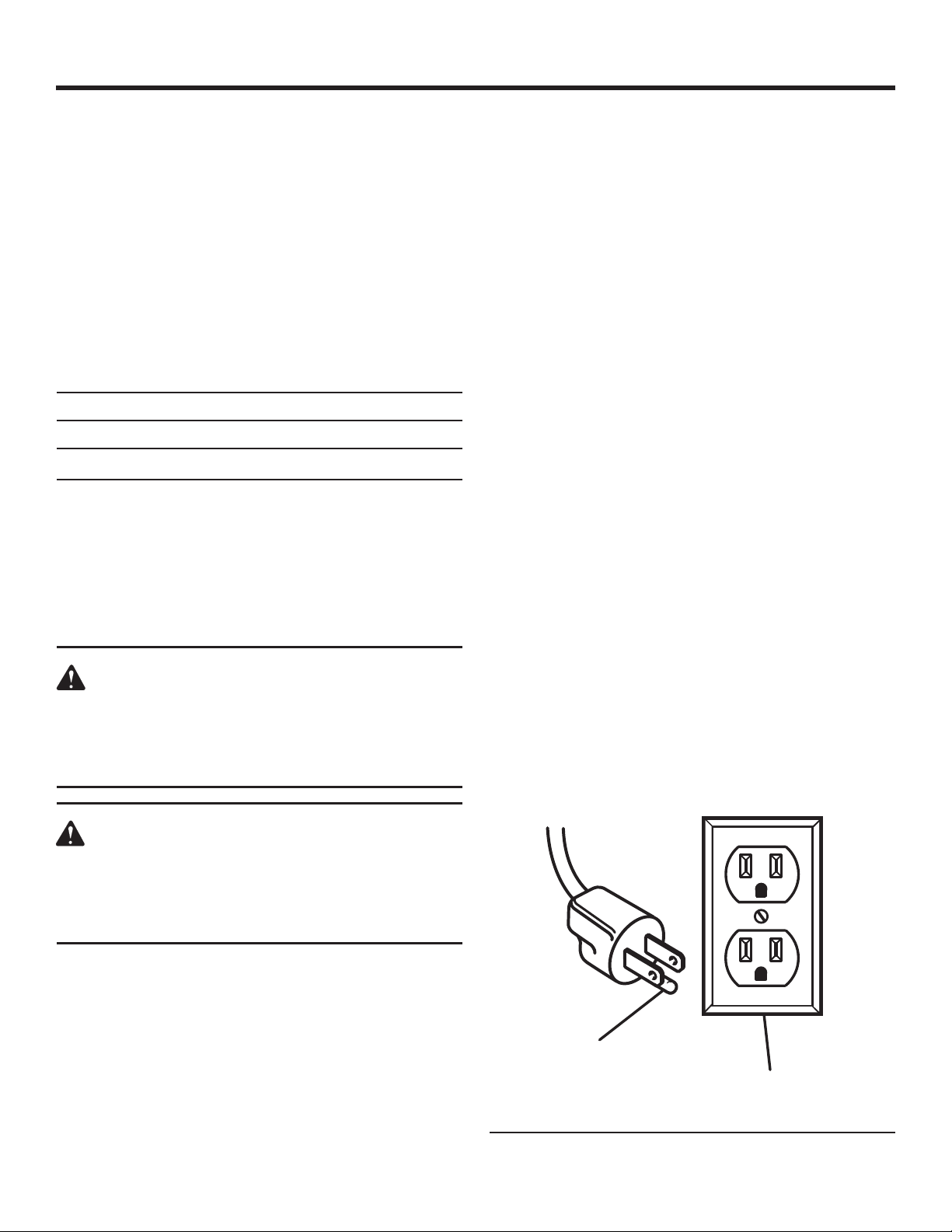
This tool is intended for use on a circuit that has an outlet
like the one shown in figure 1. It also has a grounding pin
like the one shown.
tion or breakdown, grou
nding provides
WARNING:
Check extension cords before each use. If damaged replace immediately. Never use tool with a
damaged cord since touching the damaged area
could cause electrical shock resulting in serious
injury.
ELECTRICAL CONNECTION
This tool is powered by a precision built electric motor. It
should be connected to a power supply that is 120 volts,
60 Hz, AC only (normal household current). Do not operate
this tool on direct current (DC). A substantial voltage drop
will cause a loss of power and the motor will overheat. If the
saw does not operate when plugged into an outlet, double
check the power supply.
GROUNDING
PIN
COVER OF GROUNDED
OUTLET BOX
Fig. 1
7
Page 8

GLOSSARY OF TERMS
Anti-Kickback Pawls (radial arm and table saws)
A devise which, when properly installed and maintained,
is designed to stop the workpiece from being kicked back
toward the front of the saw during a ripping operation.
Arbor
The shaft on which a blade or cutting tool is mounted.
Bevel Cut
A cutting operation made with the blade at any angle
other than 90° to the table surface.
Chamfer
A cut removing a wedge from a block so the end (or part
of the end) is angled rather than at 90°.
Compound Cut
A cross cut made with both a miter and a bevel angle.
Crosscut
A cutting or shaping operation made across the grain or
the width of the workpiece.
Cutter Head (planers and jointers)
A rotating piece of adjustable blades. The cutter head
removes material from the workpiece.
Dado Cut
A non-through cut which produces a square-sided notch
or trough in the workpiece (requires a special blade).
Featherboard
A device used to help control the workpiece by guiding it
securely against the table or fence during any ripping
operation.
FPM or SPM
Feet per minute (or strokes per minute), used in reference
to blade movement.
Freehand
Performing a cut without the workpiece being guided by a
fence, miter gauge, or other aids.
Gum
A sticky, sap-based residue from wood products.
Heel
Alignment of the blade to the fence.
Kerf
The material removed by the blade in a through cut or the
slot produced by the blade in a non-through or partial cut.
Kickback
A hazard that can occur when the blade binds or stalls,
throwing the workpiece back toward operator.
Leading End
The end of the workpiece pushed into the tool first.
Miter Cut
A cutting operation made with the workpiece at any angle
to the blade other than 90°.
Non-Through Cuts
Any cutting operation where the blade does not extend
completely through the thickness of the workpiece.
Push Blocks and Push Sticks
Devices used to feed the workpiece through the saw
blade during cutting operations. A push stick (not a push
block) should be used for narrow ripping operations.
These aids help keep the operator's hands well away from
the blade.
Pilot Hole (drill presses)
A small hole drilled in a workpiece that serves as a guide
for drilling large holes accurately.
Resaw
A cutting operation to reduce the thickness of the workpiece to make thinner pieces.
Resin
A sticky, sap-based substance that has hardened.
Revolutions Per Minute (RPM)
The number of turns completed by a spinning object in
one minute.
Ripping or Rip Cut
A cutting operation along the length of the workpiece.
Riving Knife/Spreader/Splitter (table saws)
A metal piece, slightly thinner than the blade, which helps
keep the kerf open and also helps to prevent kickback.
Saw Blade Path
The area over, under, behind, or in front of the blade. As
it applies to the workpiece, that area which will be or has
been cut by the blade.
Set
The distance that the tip of the saw blade tooth is bent (or
set) outward from the face of the blade.
Snipe (planers)
Depression made at either end of a workpiece by cutter
blades when the workpiece is not properly supported.
Throw-Back
The throwing back of a workpiece usually caused by the
workpiece being dropped into the blade or being placed
inadvertently in contact with the blade.
Through Sawing
Any cutting operation where the blade extends completely
through the thickness of the workpiece.
Workpiece or Material
The item on which the operation is being done.
Worktable
Surface where the workpiece rests while performing a
cutting, drilling, planing, or sanding operation.
8
Page 9

FEATURES
R
E
M
O
V
E
aaaa
R
E
M
O
V
E
PRODUCT SPECIFICATIONS
Motor ...................................................... 3/8 HP Induction
Phase ....................................................................... Single
Rotation of Shaft ...............................................Clockwise
No Load Speed ................................. 0-1725/rpm/spindle
No Load Speed .......................................0-1350/rpm/belt
Oscillation .............................................................. 60/min.
TRACKING KNOB
BELT
TENSION
LEVER
SANDING
SLEEVE
THROAT PLATE
Stroke ...................................................................... 3/4 in.
Sanding Sleeves ......... 1/2 in., 3/4 in., 1 in., 1-1/2 in., 2 in.
Sanding Drums ....................... 3/4 in., 1 in., 1-1/2 in., 2 in.
Sanding Belt ...................................................4 in. x 24 in.
Input .............................. 120 V, 60 Hz, AC only, 5.0 Amps
Net Weight .............................................................. 40 lbs.
SPINDLE KNOB
UPPER SPINDLE
WASHER
TABLE
INSERT
TABLE
LOCK
KNOB
WORK REST
SANDING BELT
WORKTABLE
SANDING SLEEVES /
THROAT PLATES /
WASHER STORAGE AREA
SLOTS FOR
SAW HORSE
MOUNTING
SWITCH
DUST
EXHAUST
PORT
HEX KEY
STORAGE
AREA
SANDING BELT
ASSEMBLY
TABLE INSERT / SANDING
BELT STORAGE
9
Fig. 2
Page 10

FEATURES
KNOW YOUR OSCILLATING EDGE BELT/
SPINDLE SANDER
See Figure 2.
Before attempting to use this product, familiarize yourself
with all operating features and safety rules.
SANDING BELT
Removes material from wood. Oscillates (3/4 in.) up and down
to sand faster and prevents burning of the workpiece.
BELT TENSION LEVER
Slide lever left to release the sanding belt tension; slide right
to apply belt tension.
TRACKING KNOB
Turning knob counterclockwise causes sanding belt to move
towards the table; turning knob clockwise causes sanding
belt to move away from the table.
SPINDLE KNOB
Loosen knob to remove sanding belt assembly (or sanding
drum) and change to spindle sanding (or belt sanding).
NOTE: Knob has left hand threads. Turn knob clockwise to
loosen and counterclockwise to tighten.
WORK REST
Supports the workpiece on the sanding belt.
THROAT PLATE
Fits around drum to help support workpiece.
SANDING SLEEVE/DRUM
Removes material from wood. Oscillates up and down to
sand faster and prevents burning the workpiece.
TABLE LOCK KNOB
Loosening knob allows the front table to be tilted for bevel
sanding.
DUST ExHAUST PORT
2-1/2 in. opening for wet/dry vac hook-up.
TABLE INSERT/SANDING BELT STORAGE
Holds table insert or sanding belt when not being used.
TABLE INSERT
Helps to support workpiece when drum sanding.
WORKTABLE
Equipped with a sturdy, worktable that provides a stable surface
when using either the disc sanding or the belt sanding feature.
TOOLS NEEDED
The following tools (not included) are needed for making adjustments to your tool:
STRAIGHT EDGE
COMBINATION
SQUARE
Fig. 3
10
Page 11

LOOSE PARTS
The following items are included with your tool:
Oscillating Edge Belt/Spindle Sander (1)
Throat Plates (4)
Switch Key
Hex Keys (2)
Knob
Rubber Feet (4)
Flat Washers (4),1-3/4 in. O.D., 7/8 in. O.D.,
5/8 in. O.D., 1/2 in. I.D.
Sanding Sleeves (5)
Sanding Drums (4)
Sanding Belt Assembly
Table Insert
Operator's Manual
RUBBER FEET
HEX KEYS
THROAT PLATES
SWITCH KEY
TABLE INSERT
KNOB
SANDING BELT
ASSEMBLY
1-3/4 in. O.D.
SANDING SLEEVES
WASHER
7/8 in. O.D.
WASHER
1 in.3/4 in.1/2 in.
5/8 in. O.D.
WASHER
SANDING DRUMS
1/2 in. I.D.
WASHER
1-1/2 in.
WARNING:
The use of attachments or accessories not listed might be hazardous and could cause serious
personal injury.
2 in.
Fig. 4
ASSEMBLY
UNPACKING
This product requires assembly.
Carefully lift sander from the carton by the base, and
place it on a level work surface.
NOTE: This tool is heavy. To avoid back injury, lift with
your legs, not your back, and get help when needed.
Inspect the tool carefully to make sure no breakage or
damage occurred during shipping.
Do not discard the packing material until you have care-
fully inspected and satisfactorily operated the tool.
If any parts are damaged or missing, please call
1-866-539-1710 for assistance.
WARNING:
If any parts are missing, do not operate this tool
until the missing parts are replaced. Failure to do so
could result in possible serious personal injury.
WARNING:
Do not attempt to modify this tool or create accessories not recommended for use with this tool. Any
such alteration or modification is misuse and could
result in a hazardous condition leading to possible
serious personal injury.
11
Page 12

R
E
M
O
V
E
ASSEMBLY
WARNING:
Do not connect to power supply until assembly is
complete. Failure to comply could result in accidental starting and possible serious personal injury.
MOUNTING RUBBER FEET TO BASE
See Figure 5.
Place the sander directly on the table surface.
From the parts bag locate the four rubber feet.
Place the sander on its side so the bottom of the base is
facing toward the front.
Locate the four holes in each corner of the base and place
one of the rubber feet in each of these holes.
Position sander in the upright position and apply pressure
in the downward position to ensure the feet are inserted
securely.
CAUTION:
To reduce the risk of injury from tool movement,
the supporting surface where sander is mounted
should be examined carefully after mounting to
insure no movement during use can result. If any
tipping or walking is noticed, secure to workbench
or supporting surface before operating sander.
BASE
HOLE
RUBBER
FEET
Fig. 5
MOUNTING SANDER TO WORKBENCH
See Figure 6.
If sander is to be used in a permanent location, it should be
fastened securely to a firm supporting surface, such as a
workbench, with either bolts or drywall screws.
Fastening with bolts
Use 1/4 in. bolts, washers, and nuts (not included). The
bolt length should be 1-1/2 in. plus the thickness of the
workbench.
Locate and mark the holes where the sander is to be
mounted.
Drill four 3/8 in. diameter holes through workbench.
Place sander on workbench, aligning holes in base with
holes drilled in workbench.
Insert four 1/4 in. diameter bolts and washers and attach
nuts securely.
Fastening with screws
Drive four 2-1/2 in. long screws through the holes in the
base and through the workbench. Do not overtighten the
screws.
2-1/2 in.
DRYWALL SCREW
WASHER
NUT
1/4 in. BOLT
Fig. 6
12
Page 13

R
E
M
O
V
E
ASSEMBLY
R
E
M
O
V
E
R
E
M
O
V
E
aaaa
CLAMPING SANDER TO WORKBENCH
See Figure 7.
An alternative method of mounting is to fasten the sander
to a mounting board. The board should be sufficient size to
avoid tipping while in use. Any good grade of plywood or
chipboard with a 3/4 in. thickness is recommended. (Thinner
chipboard can break.)
Once sander is mounted to board, clamp to workbench.
NOTE: For proper stability, holes must be countersunk
so screw heads are flush with the surface of supporting
board.
SUPPORTING OSCILLATING EDGE BELT/
SPINDLE SANDER TO SAWHORSES
See Figure 8.
The sander has provisions for being supported by sawhorses.
The sawhorse can be built with the crosspiece either vertical
or horizontal. Make sure the sawhorses are secure.
PARTS STORAGE
See Figures 9 - 10.
On board storage has been provided for all washers, spacers, drums, sleeves and hex keys. All front loaded parts can
be protected from incidental dislodging by lowering the table
all the way down until it rests against the base and tightening the knob.
Storage for the sanding belt assembly is provided in the
pocket on the rear of the base.
SLOTS FOR
SAW HORSE
MOUNTING
Fig. 8
C-CLAMP
MOUNTING
BOARD
HEX KEY
STORAGE
AREA
TABLE INSERT / SANDING
BELT STORAGE
WORKBENCH
Fig. 7
Fig. 9
TABLE LOCK
KNOB
SANDING SLEEVES /
THROAT PLATES / WASH-
ERS STORAGE AREA
13
Fig. 10
Page 14

ASSEMBLY
R
E
M
O
V
E
R
E
M
O
V
E
INSTALLING THE SANDING BELT ASSEMBLY
See Figure 11.
Remove the fan and clean sawdust from inside table
recess.
Slide the fan onto the motor shaft (vanes face down)
aligning slot with roll pin as shown. The fan is used in
all sanding operations.
Slide belt assembly down motor shaft. Align drive drum
splines with the slots in the fan. Place belt assembly into
the wear plate opening as shown.
Tighten spindle knob. Do not overtighten.
NOTE: Knob turns counterclockwise to tighten.
Install sanding belt (see “Removing/Installing the Sanding
Belt”, page 21).
Plug the power cord into the power source and install the
key.
REMOVING THE SANDING BELT ASSEMBLY
See Figure 12.
Loosen the work rest knob and pivot the work rest out of
the way. Tighten the work rest knob.
Remove the spindle knob and lift off the sanding belt
assembly.
NOTE: Knob turns clockwise to loosen.
Store assembly in pocket in rear of base.
MOTOR
SHAFT
SLOT
ROLL PIN
FAN
FAN
VANES
Fig. 11
SPLINES
SLOTS
SPINDLE
KNOB
WEAR PLATE
SANDING BELT
ASSEMBLY
WORK REST
KNOB
WORK REST
Fig. 12
14
Page 15

R
E
M
O
V
E
ASSEMBLY
INSTALLING SANDING SLEEVES LARGER
THAN 1/2 IN. DIAMETER
See Figures 13 - 14.
Remove the fan and clean sawdust from inside table
recess.
Slide the fan onto the motor shaft (vanes face down)
aligning slot with roll pin. The fan is used with all drums
and sleeves.
Install the table insert by sliding it over the fan.
Use a straight edge as shown to make sure the table
insert is flush with the table.
If necessary, adjust the set screws in the table insert with
the 3/32 in. hex key provided.
Slide the sanding sleeve-rubber drum onto the spindle.
NOTE: If the drum is difficult to slide over the spindle,
apply talcum powder to the spindle.
Position throat plate insert in the table recess. (See rec-
ommended throat plate insert selection area from table
on page 16). Use the smallest throat plate insert that will
fit over the drum.
Place desired sanding sleeve on correct drum.
NOTE: If the sanding sleeve is difficult to slide over the
drum, apply talcum powder to the outside surface of the
rubber drum.
Install the correct upper spindle washer and tighten the
knob. Do not overtighten.
NOTE: Knob turns counterclockwise to tighten.
Plug power cord in the power source and install the
switch key.
STRAIGHT EDGE
TABLE INSERT
SET SCREWS
3/32 in. HEX KEY
Fig. 13
KNOB
WASHER
SANDING
SLEEVE
SANDING
DRUM
THROAT PLATE
Fig. 14
15
Page 16

ASSEMBLY
INSTALLING SANDING SLEEVES FOR THE
1/2 IN. DIAMETER SANDING DRUM
See Figure 15.
Remove the fan and clean sawdust from inside table
recess.
Slide the fan onto the motor shaft (vanes face down) align-
ing slot with roll pin. The fan is used with all sanding
operations.
Install 1/2 in. I.D. washer over motor shaft.
Install the throat plate.
Use a straight edge as shown to make sure the table
insert is flush with the table. If necessary, adjust the set
screws in the table insert with the 3/32 in. hex “L” wrench
provided.
Sanding
Sleeve
Diameter
1/2 in.
3/4 in.
1 in. 1-3/16 in.
1-1/2 in. 1-11/16 in.
2 in. 2-3/16 in. 1-3/4 in.
Throat plate Insert
Opening Inside
Diameter (I.D.)
15/16 in. 5/8 in.
Upper Spindle
Washer Outside
Diameter (O.D.)
7/8 in.
KNOB
1/2 in.
SANDING
SLEEVE
1/2 in. I.D.
WASHER
1-3/4 in. O.D.
WASHER
7/8 in. O.D.
WASHER
15/16 in. I.D.
THROAT PLATE
5/8 in. O.D.
WASHER
5/8 in. O.D.
WASHER
Fig. 15
1/2 in. I.D.
WASHER
Position 15/16 in. I.D. throat plate into the table recess.
Locate 1/2 in. sanding sleeve and slide it on the spindle.
(Rubber drum is not used.)
Install the upper spindle washer and tighten the knob.
Do not overtighten.
NOTE: Knob turns counterclockwise to tighten.
Plug power cord into the power source and install the
yellow switch key.
SELECTION OF THROAT PLATE INSERTS AND
UPPER SPINDLE WASHERS
See Figure 16.
WARNING:
Using the wrong throat plate throat plate may permit small pieces of wood or finger tips to become
wedged between the abrasive surface and the
insert.
NOTE: Use the smallest throat plate that will fit over the
drum.
NOTE: Use the largest upper spindle washer that will not
protrude past sanding sleeve.
15/16 in. I.D.
THROAT PLATE
1-3/16 in. I.D.
THROAT PLATE
1-11/16 in. I.D.
THROAT PLATE
2-3/16 in. I.D.
THROAT PLATE
16
Fig. 16
Page 17

OPERATION
WARNING:
Do not allow familiarity with your tool to make you
careless. Remember that a careless fraction of a
second is sufficient to inflict severe injury.
WARNING:
Always wear safety goggles or safety glasses with
side shields when operating tools. Failure to do so
could result in objects being thrown into your eyes,
resulting in possible serious injury.
SWITCH
KEY
TO TURN ON
SWITCH
LIFT SWITCH
APPLICATIONS
This product has been designed only for the purposes listed
below:
Oscillating and Rotary Motion – for fast, burn free finishes
on edges, faces, contours, inside and outside curves.
ON-OFF SWITCH
See Figure 17.
WARNING:
Always remove the switch key when the tool is not
in use and keep it in a safe place. In the event of a
power failure, turn the switch OFF ( O ) and remove
the key. This action will prevent the tool from accidentally starting when power returns.
The ON-OFF switch has a locking feature. This feature is
intended to help prevent unauthorized and possible hazardous use by children and others.
To turn sander ON ( I ) insert key into switch.
Lift the switch button to turn on.
To turn sander OFF ( O ). Push lever in.
To lock switch in OFF ( O ) position, hold switch in with
one hand. Remove key with other hand.
CAUTION:
Before turning switch on, make sure the belt or
drum and sleeve are properly installed.
TO TURN OFF
REMOVE SWITCH KEY
PUSH SWITCH DOWN
HOLD SWITCH IN
Fig. 17
WHEN SANDER IS RUNNING
Before starting your work, watch the sander while it runs.
If it makes an unfamiliar noise or vibrates excessively, stop
immediately. Turn the sander off. Unplug the sander. Do not
restart until identifying and correcting the problem.
Before using the sander, make sure the sanding belt turns
clockwise, when viewed from above.
Don’t force tool. It will perform better and safer at its designed rate. Press workpiece against the sanding sleeve or
belt hard enough to begin sanding without bogging down
or binding spindle.
BEFORE FREEING ANY JAMMED MATERIAL:
Turn switch OFF ( O ).
Unplug the sander.
Wait for all moving parts to stop.
BEFORE LEAVING THE SANDER
Turn switch off. Don’t leave tool until the unit comes to a
complete stop.
Make workshop childproof. Remove the switch key. Store it
away from children and others not qualified to use the tool.
Disconnect master switches. Lock the shop.
17
Page 18

OPERATION
R
E
M
O
V
E
PRECAUTIONS TO TAKE WHEN SANDING
METALS
When sanding metals, sparks or hot fragments could cause
a fire. To reduce the risk of this:
Disconnect any dust collecting hose from the sander.
Remove all traces of wood dust from inside the unit before
sanding metals.
Remove all traces of metal dust from inside the unit before
sanding wood again.
PRECAUTIONS TO TAKE WHEN SANDING
PAINT
Sanding of lead-based paint is not recommended. It is difficult to control the contaminated dust that could cause lead
poisoning.
It is also difficult to identify whether or not a paint contains
lead. Therefore, we recommend the following precautions
when sanding all paints:
Protect your lungs. Wear a dust mask or respirator at all
times. Wear only dust masks that are suitable for working in lead paint sanding environments. Ordinary painting
masks do not offer this protection.
Do not allow children or pregnant women to enter the work
area until paint sanding job is complete and work area is
clean.
To prevent ingesting contaminated paint particles: Do not
eat, drink, or smoke in a work area where paint is being
sanded. After sanding paint, wash and clean up before
eating, drinking or smoking. Do not leave food, drinks, or
tobacco products in the work area where dust can settle
on them.
BASIC SANDING OPERATION
Sandpaper selection
Selecting the correct size diameter, correct size grit, and
correct type sandpaper is an extremely important step in
achieving a high quality sanded finish. Aluminum oxide,
silicon carbide, and other synthetic abrasives are best for
power sanding. Natural abrasives, such as flint and garnet,
are too soft for economical use in power sanding.
In general, coarse grit will remove the most material and finer
grit will produce the best finish in all sanding operations. The
condition of the surface to be sanded will determine which
grit will do the job. If the surface is rough, start with a coarse
grit and sand until the surface is uniform. Medium grit may
then be used to remove scratches left by the coarser grit and
finer grit used for finishing of the surface. Always continue
sanding with each grit until surface is uniform.
NOTE: Do not use sander without sandpaper. Doing so will
damage the rubber drum.
Select and install the desired sanding sleeve for the particular application. Sanding sleeves from 1/2 in. to 2 in. can be
used with this sander. Choose one that is close in size to
the workpiece you are sanding. Also install the appropriate
throat plate insert (page 16).
WARNING:
Failure to use the correct size throat plate insert
with its matching sanding sleeve could result in
fingers being pinched or the workpiece being
pulled down between the throat plate insert and
sanding sleeve.
NOTE: The correct size sanding belt is 4 in. x 24 in. These
belts are available in coarse, medium and fine grits.
SURFACE SANDING ON THE SANDING BELT
See Figure 18.
WARNING:
To reduce the risk of injury from slips, jams or
thrown pieces, adjust the work rest to clear the
sanding surface by no more than 1/16 of an inch.
When checking clearance between the sanding belt
and work rest, press the sanding belt flat against
the metal worktable beneath it.
Hold the workpiece firmly with both hands, keeping fin-
gers away from the sanding belt.
Keep the end butted against the work rest and move the
work evenly across the sanding belt. Use caution when
sanding very thin pieces.
For sanding long pieces the work rest can be rotated out
of the way.
Apply only enough pressure to allow the sanding belt to
remove material.
Do not sand thin pieces that may become trapped be-
tween the belt and work rest.
SURFACE SANDING
Fig. 18
18
Page 19

R
E
M
O
V
E
R
E
M
O
V
E
OPERATION
R
E
M
O
V
E
END SANDING ON THE SANDING BELT
See Figure 19.
Move the work evenly across the sanding belt. For
accuracy, use a miter gauge accessory (not included).
SANDING CURVED EDGES
See Figure 20.
Inside curves are best sanded with the sander assembled
in the spindle mode. However, inside curves larger than
1-1/2 in. may be sanded on the drive drum when in the belt
sander mode.
Although it is possible to lightly sand on the idler drum end of
the belt sanding assembly, it is not recommended. The idler
drum is an integral part of the belt tracking mechanism. It
is spring loaded to maintain proper tension. Use of the idler
drum to sand curves may cause belt to track improperly.
FEED DIRECTION
See Figure 21.
WARNING:
To prevent thrown workpiece, feed workpiece
against sanding sleeve from left to right as
shown.
END SANDING
Fig. 19
CURVED EDGE SANDING
The sanding sleeve rotates clockwise. Feed the workpiece
against the sanding sleeve from left to right as shown. When
fed from left to right, the rotation of the sanding sleeve sands
against the workpiece. If fed in the opposite direction, the
rotation forces of the spinning sanding sleeve will tend to
throw or bounce the workpiece away from the sanding
sleeve. This could cause loss of control of workpiece or
possible injury.
Fig. 20
FEED DIRECTION
19
Fig. 21
Page 20

R
E
M
O
V
E
DRIVE DRUM - Sanding drums mount here.
T
R
A
C
K
IN
G
/
ID
L
E
R
D
R
U
M
N
o
t re
c
o
m
m
e
n
d
e
d
fo
r
s
a
n
d
in
g
.
B
E
L
T
R
O
T
A
T
I
O
N
ADJUSTMENTS
R
E
M
O
V
E
WARNING:
Before performing any adjustment, make sure
the tool is unplugged from the power supply and
the switch is in the OFF ( O ) position. Failure to
heed this warning could result in serious personal
injury.
SqUARING FRONT TABLE
See Figure 22.
NOTE: Use a combination square to check the angle of the
front table with the sanding belt.
If the front table is not 90° to the sanding belt:
Use the hex key provided and “back out” both set screws
located on each side of the table.
Loosen the front table lock knob and adjust the front table
90° to the sanding belt.
Tighten the front table lock knob.
Adjust both set screws to contact the front table.
Adjust detent if necessary
Loosen the two pan head screws that secure the detent.
Adjust detent so that it engages the notches in the bracket
table lock.
Tighten the two pan head screws.
ALIGNING BELT TO MITER GAUGE SLOT
See Figure 23.
The sanding belt is installed at the factory; however, check
and make sure the belt is parallel to the miter gauge
groove:
Use a combination square to check the distance from the
miter gauge groove to the belt assembly as shown.
If adjustment is required, use a 5/32 in. hex key provided
with unit to loosen the two flat head socket recess screws
on the table.
Adjust the worktable as needed to make it parallel or
same distance to the miter gauge slot.
Tighten two screws.
SANDING
BELT
FRONT TABLE
SET SCREW
HEX KEY
SOCKET RECESS
ADJUST WORKTABLE
PARALLEL MITER
GAUGE SLOT
NOTCHES IN
BRACKET TABLE
TABLE
LOCK
KNOB
SCREWS
LOCK
COMBINATION
SQUARE
PAN HEAD
SCREWS
DETENT
Fig. 22
HEX KEY
MITER GAUGE
GROOVE
20
Fig. 23
Page 21

R
E
M
O
V
E
R
E
M
O
V
E
ADJUSTMENTS
REMOVING/INSTALLING THE SANDING BELT
See Figures 24 - 26.
Tensioning and Tracking
Some sanding belts have a “directional arrow” on the inside
or smooth side. If there is an arrow, the belt must run in the
direction of the arrow so the splice will not come apart. If
there is no arrow the belt may be put on either direction.
Slide the tension lever to the left to release the belt
tension.
Remove the sanding belt.
Place the replacement sanding belt over the drums as
shown. Make sure the belt is centered on both drums.
Slide the tension lever to the right to apply belt tension.
Plug in the power cord. Insert the switch key and turn the
unit ON ( I ) and immediately OFF ( O ), noting if the belt
tends to slide off the drums. If it did not tend to slide off,
it is tracking properly.
If the sanding belt runs down towards the table, turn the
tracking knob clockwise 1/4 turn.
If the sanding belt, runs up away from the table, turn the
tracking knob counterclockwise 1/4 turn.
Turn switch ON ( I ) and immediately OFF ( O ) again, noting
belt movement. Readjust tracking knob if necessary.
TRACKING KNOB
SANDING BELT
TO RELEASE
TO TIGHTEN
TENSIONING
LEVER
Fig. 24
DIRECTIONAL ARROW
Fig. 25
TRACKING
KNOB
CLOCKWISE
(MOVES BELT UP)
COUNTERCLOCKWISE
(MOVES BELT DOWN)
21
Fig. 26
Page 22

MAINTENANCE
WARNING:
When servicing use only identical RIDGID replacement parts. Use of any other parts may create a
hazard or cause product damage.
WARNING:
Always wear safety goggles or safety glasses with
side shields during power tool operation or when
blowing dust. If operation is dusty, also wear a
dust mask.
GENERAL MAINTENANCE
Avoid using solvents when cleaning plastic parts. Most
plastics are susceptible to damage from various types of
commercial solvents and may be damaged by their use. Use
clean cloths to remove dirt, dust, oil, grease, etc.
WARNING:
Do not at any time let brake fluids, gasoline, petroleum-based products, penetrating oils, etc., come
in contact with plastic parts. Chemicals can damage, weaken or destroy plastic which may result in
serious personal injury.
LUBRICATION
All of the bearings in this tool are lubricated with a sufficient
amount of high grade lubricant for the life of the unit under
normal operating conditions. Therefore, no further lubrication
is required.
DUST COLLECTION CAPABILITY
See Figure 27.
A standard 2-1/2 in. dust exhaust port has been provided
to make dustless sanding possible. It is on the rear of the
sander as shown. The pickup adapter end of a vacuum hose
fits inside the dust exhaust port with a wedge fit.
Even with a dust collection system, it is necessary to periodically clean sanding dust from the recess in the table.
Sawdust buildup in the table recess may prevent the belt
or spindle from making a complete oscillation, which may
cause premature wear.
TRANSPORTING SANDER
When using the sander in a portable application, it is acceptable to lift and carry sander by the worktable or by the carry
handles. Be careful when transporting to reduce the risk of
dislodging accessories, throat plate inserts, wrench, and upper spindle washers from their respective storage areas.
Electric tools used on fiberglass material, wallboard, spackling compounds, or plaster are subject to accelerated wear
and possible premature failure because the fiberglass chips
and grindings are highly abrasive to bearings, brushes, commutators, etc. Consequently, it is not recommended using
this tool for extended work on these types of materials. However, if you do work with any of these materials, it is extremely
important to clean the tool using compressed air.
DUST
EXHAUST
PORT
PICKUP ADAPTER
VACUUM HOSE
Fig. 27
22
Page 23

ACCESSORIES
The following recommended accessories are currently
available at Home Depot stores:
Miter Gauge ........................................................... AC1021
Switch Key ............................................................ AC1000
Universal Legset .................................................... AC9910
Replacement Sanding Sleeves, 2 pk. See Chart Below
Size
1/2 in.
3/4 in.
1 in.
1-1/2 in.
2 in.
Grit
Fine
Medium
Coarse
Fine
Medium
Coarse
Fine
Medium
Coarse
Fine
Medium
Coarse
Fine
Medium
Coarse
SKU No.
AC7001
AC7002
AC7003
AC7004
AC7005
AC7006
AC7007
AC7008
AC7009
AC7010
AC7011
AC7012
AC7013
AC7014
AC7015
Do not use any accessory unless you have received and
read complete instructions for its use.
NOTE: 4 in. x 24 in. replacement sanding belts are available
at your local Home Depot store.
WARNING:
Current attachments and accessories available for
use with this tool are listed above. Do not use any
attachments or accessories not recommended by
the manufacturer of this tool. The use of attachments or accessories not recommended can result
in serious personal injury.
23
Page 24

TROUBLESHOOTING
Problem Cause Solution
Excessive noise NOTE: The
sander will make some noise
when it is operating normally
Motor fails to develop full
power, starts slowly, or fails
to come up to full speed.
NOTE: Low voltage
Motor overheats
Motor stalls (resulting
in blown fuses or circuit
breakers)
Frequent opening of fuse or
circuit breaker
1. Motor gearbox not operating
correctly.
1. Circuit overloaded with lights,
appliances and other motor.
2. General overloading of power
company facilities.
3. Motor relay not operating.
1. Motor overloaded.
1. Motor relay not operating.
2. Voltage too low. Circuit overloaded
or general overloading of power
company facilities.
3. Incorrect fuses or circuit breakers
in power line.
1. Motor overloaded.
2. Incorrect fuses or circuit breaker in
power line.
3. Relay not operating.
1. Consult Authorized Service Center; any attempt to repair
this motor or gearbox may create a hazard unless repair is
done by a qualified service technician.
1. Do not use sander on heavily loaded circuits.
2. Request a voltage check by qualified electrician.
3. Have relay replaced. Consult Authorized Service Center.
Any attempt to repair this relay may create a hazard unless
repair is done by a qualified service technician.
1. Reduce pressure on workpiece.
1. Have relay replaced. Consult Authorized Service Center.
Any attempt to repair this relay may create a hazard unless
repair is done by a qualified service technician.
2. Request voltage check by qualified electrician.
3. Install correct fuse or circuit breaker.
1. Feed work slower.
2. Install correct fuse or circuit breakers.
3. Have relay replaced. Consult Authorized Service Center.
Any attempt to repair this relay may create a hazard unless
repair is done by a qualified service technician.
Motor will not run
Sanding drum or belt slips or
slows down easily
Wood burns while sanding
Sandpaper doesn’t remove
material
Spindle doesn’t go
through full 3/4 in. travel
1. Damaged On-Off Switch/Cord.
2. Burned out motor, no power to
motor or low voltage.
1. Applying too much pressure to
workpiece.
2. Spindle knob too loose.
1. Sanding drum is glazed with sap.
1. Sandpaper is compacted with
sawdust.
1. Sawdust is compacted under lower
drum washer.
2. Fan not installed.
3. Damaged gearbox.
24
1. Replace damaged parts before using sander.
2. Consult Authorized Service Center. Any attempt to repair
this motor may create a hazard unless repair is done by a
qualified service technician.
1. Ease up on workpiece.
2. Tighten spindle knob.
1. Replace sandpaper.
1. Replace sandpaper.
1. Vacuum sawdust from area of lower drum washer.
2. Ensure that fan is installed with vanes face down.
3. Consult Authorized Service Center. Any attempt to repair
this gearbox may create a hazard unless repair is done by
a qualified service technician.
Page 25

WARRANTY
RIDGID® HAND HELD AND STATIONARY POWER TOOL
3 YEAR LIMITED SERVICE WARRANTY
Proof of purchase must be presented when requesting warranty service.
Limited to RIDGID® hand held and stationary power tools
purchased 2/1/04 and after. This product is manufactured
by One World Technologies, Inc. The trademark is licensed
from RIDGID, Inc. All warranty communications should be
directed to One World Technologies, Inc., attn: RIDGID Hand
Held and Stationary Power Tool Technical Service at (toll
free) 1-866-539-1710.
90-DAY SATISFACTION GUARANTEE POLICY
During the first 90 days after the date of purchase, if you are
dissatisfied with the performance of this RIDGID® Hand Held
and Stationary Power Tool for any reason you may return
the tool to the dealer from which it was purchased for a full
refund or exchange. To receive a replacement tool you must
present proof of purchase and return all original equipment
packaged with the original product. The replacement tool
will be covered by the limited warranty for the balance of
the 3 YEAR service warranty period.
WHAT IS COVERED UNDER THE 3 YEAR
LIMITED SERVICE WARRANTY
This warranty on RIDGID® Hand Held and Stationary Power
Tools covers all defects in workmanship or materials and normal wear items such as brushes, chucks, motors, switches,
cords, gears and even cordless batteries in this RIDGID
tool for three years following the purchase date of the tool.
Warranties for other RIDGID® products may vary.
HOW TO OBTAIN SERVICE
To obtain service for this RIDGID® tool you must return it;
freight prepaid, or take it in to an authorized service center
for RIDGID® branded hand held and stationary power tools.
You may obtain the location of the authorized service center
nearest you by calling (toll free) 1-866-539-1710 or by logging on to the RIDGID® website at www.ridgid.com. When
requesting warranty service, you must present the original
dated sales receipt. The authorized service center will repair any faulty workmanship, and either repair or replace
any part covered under the warranty, at our option, at no
charge to you.
WHAT IS NOT COVERED
This warranty applies only to the original purchaser at retail
and may not be transferred. This warranty only covers defects arising under normal usage and does not cover any
malfunction, failure or defect resulting from misuse, abuse,
neglect, alteration, modification or repair by other than an
authorized service center for RIDGID® branded hand held
and stationary power tools. Consumable accessories provided with the tool such as, but not limited to, blades, bits
and sand paper are not covered.
RIDGID, INC. AND ONE WORLD TECHNOLOGIES, INC.
MAKE NO WARRANTIES, REPRESENTATIONS OR
PROMISES AS TO THE qUALITY OR PERFORMANCE
OF ITS POWER TOOLS OTHER THAN THOSE SPECIFICALLY STATED IN THIS WARRANTY.
ADDITIONAL LIMITATIONS
To the extent permitted by applicable law, all implied warranties, including warranties of MERCHANTABILITY or FITNESS FOR A PARTICULAR PURPOSE, are disclaimed. Any
implied warranties, including warranties of merchantability
or fitness for a particular purpose, that cannot be disclaimed
under state law are limited to three years from the date of
purchase. One World Technologies, Inc. and RIDGID, Inc.
are not responsible for direct, indirect, incidental or consequential damages. Some states do not allow limitations on
®
how long an implied warranty lasts and/or do not allow the
exclusion or limitation of incidental or consequential damages, so the above limitations may not apply to you. This
warranty gives you specific legal rights, and you may also
have other rights which vary from state to state.
One World Technologies, Inc.
Hwy. 8
Pickens, SC 29671
25
Page 26

OPERATOR’S MANUAL
OSCILLATING EDGE BELT/
SPINDLE SANDER
EB44241
983000-482
1-30-08 (REV: 01)
Customer Service Information:
For parts or service, contact your nearest RIDGID authorized service center. Be
sure to provide all relevant information when you call or visit. For the location of
the authorized service center nearest you, please call 1-866-539-1710 or visit
us online at www.ridgid.com.
The model number of this tool is found on a plate attached to the motor housing.
Please record the serial number in the space provided below. When ordering
repair parts, always give the following information:
Model No.
Serial No.
EB44241
 Loading...