

Page 1

A-Frame Operator’s Manual
A-Frame Fault Locator
Model FT-103 Transmitter and
Model FR-30 Receiver
• Français – 15
• Castellano – pág. 33
Find Quality Products Online at: sales@GlobalTestSupply.com
www.GlobalTestSupply.com
Page 2

A-Frame Fault Locator
Table of Contents
Recording Form for Machine Serial Number .....................................................................1
Safety Symbols.....................................................................................................................2
General Safety Rules
Work Area Safety...............................................................................................................2
Electrical Safety.................................................................................................................2
Personal Safety .................................................................................................................2
Equipment Use and Care ..................................................................................................2
Service ..............................................................................................................................3
Specific Safety Information
A-Frame Fault Locator Safety............................................................................................3
RIDGID Contact Information................................................................................................4
Description............................................................................................................................4
Transmitter.........................................................................................................................4
Receiver ............................................................................................................................5
Specifications.......................................................................................................................5
Standard Equipment..........................................................................................................6
Changing/Installing Batteries..............................................................................................6
Transmitter.........................................................................................................................7
Receiver (A-Frame) ...........................................................................................................7
Pre-Operation Inspection ....................................................................................................7
Set-Up And Operation Instructions ....................................................................................7
Fault Locating
Connecting Transmitter......................................................................................................8
Locating.............................................................................................................................9
Locating Below Paved Surfaces ......................................................................................10
Multiple Faults..................................................................................................................11
Path Locating
Direct Connect Path Locating Method .............................................................................11
Inductive Clamp Path Locating ........................................................................................12
Broadcast Inductive Path Locating ..................................................................................12
Storage ................................................................................................................................13
Maintenance
Cleaning ..........................................................................................................................13
Calibration .......................................................................................................................13
Service And Repair..........................................................................................................13
Optional Equipment ...........................................................................................................14
Disposal ..............................................................................................................................14
Battery Disposal ..............................................................................................................14
EC Declaration of Conformity............................................................................................14
FCC Statement....................................................................................................................14
Electromagnetic Compatibility (EMC) ..............................................................................14
Lifetime Warranty .................................................................................................Back Cover
*Original Instructions - English
ii
Find Quality Products Online at: sales@GlobalTestSupply.com
www.GlobalTestSupply.com
999-995-095.10_REV. A
Page 3

A-Frame Fault Locator
A-Frame Fault Locator
Model FT-103 Transmitter and
Model FR-30 Receiver
WARNING!
Read this Operator’s Man ual
carefully before using this
tool. Failure to understand
and follow the contents of this
manual may result in electrical shock, fire and/or serious
person al injury.
Find Quality Products Online at: sales@GlobalTestSupply.com
www.GlobalTestSupply.com
A-Frame Fault Locator
Record Serial Number below and retain product serial number which is located on nameplate.
Serial
No.
Page 4
A-Frame Fault Locator
Safety Symbols
In this operator’s manual and on the product, safety symbols and signal words are used to
communicate important safety information. This section is provided to improve understanding of these signal words and symbols
This is the safety alert symbol. It is used to alert you to potential personal injury hazards.
Obey all safety messages that follow this symbol to avoid possible injury or death.
DANGER
WARNING
CAUTION
NOTICE
This symbol means read the operator’s manual carefully before using the equipment. The operator’s manual contains important information on the safe and proper operation of the equipment.
This symbol means always wear safety glasses with side shields or goggles when handling
or using this equipment to reduce the risk of eye injury.
This symbol indicates the risk of electrical shock.
DANGER indicates a hazardous situation which, if not avoided, will result in death or
serious injury.
WARNING indicates a hazardous situation which, if not avoided, could result in
death or serious injury.
CAUTION indicates a hazardous situation which, if not avoided, could result in minor
or moderate injury.
NOTICE indicates information that relates to the protection of property.
.
General Safety Rules
WARNING
Read all safety warnings and instructions. Failure to follow the warnings and
instructions may result in electric shock,
fire and/or serious injury.
SAVE ALL WARNINGS
AND INSTRUCTIONS FOR
FUTURE REFERENCE!
Work Area Safety
• Keep your work area clean and well lit.
Cluttered or dark areas invite accidents.
• Do not operate equipment in explosive
atmospheres, such as in the presence of
flammable liquids, gases or dust. E quip -
ment can create sparks which may ignite
the dust or fumes.
• Keep children and by-standers a way
while operating equipment. Distrac tions
can cause you to lose control.
Electrical Safety
• Avoid body contact with earthed or
ground ed surfaces such as pipes, radiators, ranges and refrigerators. There
is an increased risk of electrical shock if
your body is earthed or grounded.
• Do not expose equipment to rain or wet
conditions. Water en tering equipment will
increase the risk of electrical shock.
Personal Safety
• Stay alert, watch what you are doing
and use common sense when operating equipment. Do not use equipment
while you are tired or under the influence of drugs, alcohol or medication. A
moment of inattention while operating
equipment may result in serious personal
injury.
• Use personal protective equipment. Al -
ways wear eye protection. Protective equipment such as dust mask, non-skid safety
shoes, hard hat or hearing protection used
for appropriate conditions will reduce personal injuries.
• Do not overreach. Keep proper footing
and balance at all times. This enables
better control of the power tool in unexpected situations.
• Do not let familiarity gained from fre-
quent use of tools allow you to become
complacent and ignore tool safety principles. A careless action can cause severe
injury within a fraction of a second.
Equipment Use and Care
• Do not force equipment. Use the correct
equipment for your application. The cor-
2
Find Quality Products Online at: sales@GlobalTestSupply.com
www.GlobalTestSupply.com
999-995-095.10_REV. A
Page 5

A-Frame Fault Locator
rect equipment will do the job better and
safer at the rate for which it is designed.
• Do not use equipment if the switch does
not turn it ON and OFF. Any tool that cannot be controlled with the switch is dangerous and must be repaired.
• Remove the battery pack from the equip-
ment before making any adjustments,
changing accessories, or storing. Such
preventive safety measures reduce the risk
of injury.
• Store idle equipment out of the reach of
children and do not allow persons unfamiliar with the equipment or these instructions to operate the equipment.
Equipment can be dangerous in the hands
of untrained users.
• Maintain equipment. Check for missing
parts, breakage of parts and any other
condition that may affect the equipment’s
operation. If damaged, have the equipment repaired before use. Many accidents
are caused by poorly maintained equipment.
• Use the equipment and accessories in
accordance with these instructions,
taking into account the working conditions and the work to be performed.
Use of the equipment for operations different from those intended could result in a
hazardous situation.
• Keep handles and grasping surfaces
dry, clean and free from oil and grease.
Slippery handles and grasping surfaces
do not allow for safe handling and control of
the tool in unexpected situations.
Service
• Have your equipment serviced by a qual i fied repair person using on ly identical
replacement parts. This will ensure that the
safety of the tool is maintained.
Specific Safety
Information
WARNING
This section contains important safety information that is specific to this tool.
Read these precautions carefully before
using the RIDGID
to reduce the risk of electrical shock or
serious personal injury.
®
A-Frame Fault Locator
SAVE ALL WARNINGS
AND INSTRUCTIONS FOR
FUTURE REFERENCE!
Keep this manual with the tool for use by
the operator.
A-Frame Fault Locator Safety
• Do not expose the equipment to water
or rain. This increases the risk of electrical
shock.
• Do not operate the transmitter if opera-
tor or transmitter is standing in water.
Operating transmitter while in water increases the risk of electrical shock.
• Do not connect to live voltage or ac-
tive utility lines. Disconnect the conductor
to be tested from any other service, components, or anything that might be affected
by high voltage. De-energize any circuits in
or around the work area.
• Always attach transmitter test leads be-
fore turning unit ON and turn unit OFF
before disconnecting leads. This will re-
duce the risk of electrical shock.
• Never turn transmitter ON when anyone
is touching the conductor, ground stake,
or any part of the transmitter. Tur n O F F
transmitter before touching test lead or any
un-insulated conductor.
• Do not use where a danger of high volt-
age contact is present. Do not attach
leads to high voltage conductors. The
equipment is not designed to provide high
voltage protection and isolation.
• Locating equipment uses electromag-
netic fields that can be distorted and interfered with. More than one utility may
be present in a given area. Follow local
guidelines and one call/call before you dig
service procedures. Exposing a utility is
the only way to verify its existence, location
and depth.
• Avoid traffic. Pay close attention to mov-
ing vehicles when using on or near
roadways. Wear visible clothing or reflec-
tor vests.
• Before operating the RIDGID A-Frame
Fault Locator, read and understand this
operator’s manual and the instructions
for any other equipment used. Failure to
follow all instructions and warnings may result in property damage and/or serious injury.
999-995-095.10_REV. A
Find Quality Products Online at: sales@GlobalTestSupply.com
www.GlobalTestSupply.com
3
Page 6
A-Frame Fault Locator
• Use this manual in conjunction with all
company, utility or facility procedures
and policies. Familiarize yourself with all
required procedures and policies, including
safety practices, prior to entering an area
and using the equipment.
NOTICE
Ridge Tool Company, its affiliates
and suppliers, will not be liable for any injury or
any direct, indirect, incidental or consequential
damages sustained or incurred by reason of
the use of the A-Frame Fault Locator.
RIDGID Contact
Information
If you have any question concerning this
RIDGID
– Contact your local RIDGID distributor.
(800)
®
product:
Receiver
Black Test Lead
(To Ground Stake)
Red Test Lead
(To Conductor)
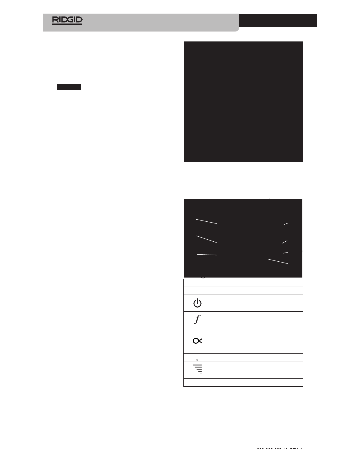
Figure 1 – A-Frame Fault Locator
Transmitter
Transmitter
Transmitter Controls:
9
Ground Stake
4
Description
The RIDGID®A-Frame Fault Locator is a highly
sensitive transmitter and receiver specifically
designed to detect the location of a path to
ground fault (Direct Fault Finding (DFF)) in
the insulation of a buried conductor (such as a
wire or cable). Damaged insulation, severed
conductor, and other faults with ground leakage are easily and precisely located.
Model FT-103 Transmitter connects to the insulated conductor and establishes a current flow,
the current leaks to ground through the insulation fault and back to the ground stake. Model
FR-30 Receiver detects the current flow to
ground through the insulation fault. The receiver provides audio and visual indications of
both signal strength and direction to assist in
detecting and locating the fault. For the AFrame fault detector to work, the conductor
must be in contact with the earth – it will not
work with conductors in conduit.
Additionally, the transmitter can be used to
apply a signal to the conductor for path locating with other receivers, such as RIDGID
SeekTech
done by direct connect and inductive methods.
Multiple frequencies and power levels are provided.
®
or NaviTrack®Locators. This can be
1
2
3
9
# Icon Description
1. — LCD Screen
2. ON/OFF and Inductive Mode Switch
3. Frequency Selection
4. — Serial and Warning Label (back of unit)
5. Inductive Clamp Jack
6. — Positive Terminal (to Conductor)
7. Negative Terminal (to Ground Stake)
8. Signal Power Setting
9. — Broadcast Inductive Decal (top and bottom)
Figure 2 – Transmitter Controls
Main Power Switch – Short press turns unit ON/OFF
Long press (5 seconds) enables Broadcast Inductive mode.
Selects the frequency of transmitter from preloaded frequencies. See Specifications for frequencies
Depressing the Signal Power Button cycles the Signal
Power between Low, Medium and High
5
6
7
8
4
Find Quality Products Online at: sales@GlobalTestSupply.com
www.GlobalTestSupply.com
999-995-095.10_REV. A
Page 7

A-Frame Fault Locator
Transmitter Display:
2
3
4
Number Icons Description
1 – – – kHz Frequency. “dFF” shown for fault finding.
2 Signal Power - # Of Bars On Increases with Increasing Power. Three Levels – Low, Medium
3
4 Voltage Warning – Transmitter connected to energized conductor – risk of electrical shock.
5 Transmitter Set for Fault Finding (dFF displayed in Frequency area (1)).
6 Transmitter Set for Inductive Clamp Use for Path Locating (Insert Inductive clamp into Jack)
7 Transmitter Set for Direct Connect Use for Fault Finding or Path Locating.
8 Transmitter Set for Broadcast Inductive Mode for Path Locating.
9 Transmitter Battery Status.
–––
and High.
Circuit Information, mA, V or Resistance in Ohms. Transmitter cycles through each at 2
second intervals.
Do not touch transmitter, leads or connections. Use high voltage precautions to disconnect.
1
5
6
7
8
9
Figure 3 – Transmitter Display
Receiver
Battery
Compartment
Serial Label
Warning
Label
Rear
Spike
Figure 4 – A Frame Receiver
Screen and
Front
Spike
Display
Controls
Receiver Controls/Display:
1
# Icon Description
1 Reference Button
Ref
2 ON/OFF Button
3 Directional Arrow
4
––
5 Low Battery Indicator
2
Stores and displays starting signal strength when pressed.
Main Power Switch – Press to turn unit ON/OFF
Indicates direction of fault
Signal Strength
Displays absolute signal Strength from 0 to 99.
Figure 5 – Receiver Controls
3
4
5
Specifications
FT-103 Transmitter:
Operating
Frequencies .......Direct Fault Finding:
797 Hz - “dFF” displayed
999-995-095.10_REV. A
Find Quality Products Online at: sales@GlobalTestSupply.com
www.GlobalTestSupply.com
5
Page 8

A-Frame Fault Locator
Path locating:
128 Hz, 1 kHz, 8 kHz, 33
kHz, 93 kHz
Direct Connect:
128 Hz, 1 kHz, 8 kHz, 33
kHz, 93 kHz
Inductive Clamp:
8 kHz, 33 kHz, 93 kHz
Broadcast Inductive:
33 kHz, 93 kHz
Load Range .......5 Ω to 2M Ω
Output Power.....Up to 3 Watts (Low,
medium and high settings)
Output Voltage ...5 Volts - 600 Volts
Power Supply .....8 × C (R14) Cell
Batteries, 12 Volt
Battery Life.........Continuous: up to 15 hours,
Intermittent: up to 60 hours
(on low at 1000 Ohm load)
Operating
Temperature .......-4°F to 133°F
(-20°C to 55°C)
Storage
Temperature.......-13°F to 140°F
(-25°C to 60°C)
IP Rating ............IP54
Size....................8.5" x 5.8" x 2.5"
(21 cm x 15 cm x 6 cm)
Weight................2.2 lbs. (1 kg)
Test Lead
Jacks..................0.16" (4mm) as per
IEC61010
FR-30 A-Frame Receiver:
Operating
Frequencies .......Fault Finding:
797 Hz - “dFF” displayed
Direct Connect:
Power Supply.....6 × AA (LR6) Batteries,
9 Volt
Battery Life..........Continuous: up to 40 hours,
Intermittent: up to 82 hours
Operating
Temperature .......-4°F to 133°F
(-20°C to 55°C)
Storage
Temperature.......-13°F to 140°F
(-25°C to 60°C)
IP Rating ............IP54
Size....................30.3" x 30.4" x 1.5"
(77 cm x 77 cm x 4 cm)
Weight................3 lbs. (1.3 kg)
Standard Equipment
The A-Frame Fault Locator package includes
the following items:
• FR-30 A-Frame Receiver
• FT-103 Transmitter
• Ground Stake
• Red and Black Test Leads (7.5' (2.3 m) long)
• Carry Cases
• Batteries
• Operator’s Manual Pack
NOTICE
This equipment is used for conductor fault and path locating. Incorrect use or
improper application may result in incorrect or
inaccurate locating. Selection of appropriate locating methods for the conditions and proper
operation is the responsibility of the user.
Changing/Installing
Batteries
WARNING
Switch unit OFF and remove any connections from the Transmitter/Receiver
before changing batteries.
Fault Finding
Depth .................Up to 20' (6m) (depend-
ing on conditions)
Fault Finding
Length................Up to 3 miles (4800 m)
(depending on conditions)
Display ...............Black and White LCD
Audio
Indication ...........Piezo Response
6
Find Quality Products Online at: sales@GlobalTestSupply.com
www.GlobalTestSupply.com
The A-Frame Fault Locator is supplied without
the batteries installed. Remove the batteries
prior to storage to avoid battery leakage. When
the low battery indicator appears on the transmitter ( ) or receiver ( ) display, the batteries need to be replaced.
NOTICE
Use the batteries that are of same
type. Do not mix battery types. Do not mix
new and used batteries. Mixing batteries can
cause overheating and battery damage.
999-995-095.10_REV. A
Page 9

A-Frame Fault Locator
Transmitter:
1. With device OFF, remove the battery compartment cover. If needed, remove batteries (Figure 6).
Battery Compartment
+
-
+
-
+
-
Batteries
Figure 6 – Changing the Batteries (Transmitter)
+
-
Cover
2. Install eight new C Cell alkaline batteries
(R14), observing correct polarity as indicated in the battery compartment.
3. Securely reinstall the battery compartment cover.
Receiver (A-Frame):
1. With device OFF, unscrew the battery
com partment cover on the top tube (Fi -
gure 7). If needed, remove batteries.
Battery
Compartment Cover
Fault Locator and correct any problems
to reduce the risk of serious injury from
electric shock and other causes, and
prevent equipment damage.
1. Make sure the transmitter and receiver
units are OFF.
2. Remove the batteries and inspect for
signs of damage. Replace if necessary.
Do not use if the batteries are damaged.
3. Clean the equipment. This aids inspection
and helps prevent the tool from slipping
from your grip.
4. Inspect the locator for the following:
• Proper assembly, maintenance and com -
pleteness.
• Any broken, worn or missing parts.
• Inspect the transmitter test leads for
damaged insulation or exposed wire.
• Presence and readability of the transmit-
ter and receiver warning labels (Figure
2 and 4).
• Any other condition which may prevent
safe and normal operation.
If any problems are found, do not use
the A-Frame Fault Locator until the problems have been repaired.
5. Inspect and maintain any other equipment being used per its instructions to
make sure it is functioning properly.
Set-Up And Operation
Instructions
Batteries
Figure 7 – Changing the Batteries (Receiver)
2. Install six new AA alkaline batteries (LR6),
observing correct polarity as indicated
in the battery compartment.
3. Securely reinstall the battery compartment cover.
Pre-Operation Inspection
WARNING
Daily before use, inspect your A-Frame
999-995-095.10_REV. A
Find Quality Products Online at: sales@GlobalTestSupply.com
www.GlobalTestSupply.com
Do not connect to live voltage or active
utility lines. Disconnect the conductor
to be tested from any other service, components, or anything that might be affected by high voltage. De-energize any
circuits in or around the work area.
Always attach transmitter test leads before turning unit ON and turn unit OFF before disconnecting leads. This will reduce the risk of electrical shock.
Never turn transmitter ON the unit when
anyone is touching the conductor, ground
stake, or any part of the transmitter. Turn
WARNING
7
Page 10

A-Frame Fault Locator
OFF transmitter before touching test lead
or any un-insulated conductor.
Do not use where a danger of high voltage contact is present. Do not attach
leads to high voltage conductors. The
equipment is not designed to provide
high voltage protection and isolation.
Locating equipment uses electromagnetic fields that can be distorted and interfered with. More than one utility may
be present in a given area. Follow local
guidelines and one call/call before you dig
service procedures. Exposing a utility is
the only way to verify its existence, location and depth.
Follow set up and operating instructions
to reduce the risk of injury from electrical
shock and other causes and to prevent
tool damage
Model FT-103 Transmitter and Model FR-30
Receiver are used for fault locating of conductors through direct connect method.
The Model FT-103 Transmitter only can be
used for path locating with RIDGID SeekTech
and NaviTrack®Locators. This can be done by
direct connect and inductive methods.
1. Confirm have appropriate work area (See
General Safety Rules). Operate in clear,
level, stable, dry location.Do not use transmitter while standing in water.
2. Determine the correct equipment for the
application, see Description and Specifi -
cations sections.
3. Make sure all equipment has been inspected and set up as directed in their instructions.
Fault Locating
It is good practice to locate the conductor path
before attempting to fault locate. This can be
done using a variety of RIDGID locating equipment. If during the location of the conductor
path an unusual amount of signal loss occurs,
this may give some indication of the conductor
insulation fault location. Additionally, use visual
cues and past history to aid in identifying the
conductor path and potential fault locations.
Once the conductor path is determined, the
RIDGID FT-103 Transmitter and FR-30 A-Frame
Receiver can be used to locate ground faults in
the insulated conductor. The Model FT-103
Transmitter connects to the insulated conductor
and establishes a current flow, the current
leaks to ground through the insulation fault
and back to the ground stake. The Model FR-30
Receiver detects the current flow to ground
through the insulation fault. For the A-Frame
fault detector to work, the conductor must be in
contact with the earth – it will not work with conductors in conduit. Generally, the A-Frame Fault
Locator works best in earth. Use with gravel,
asphalt, concrete or other ground covers may
not work as well.
The signal strength at the fault depends on
the amount of current leaking there. The greater
the leakage, the greater the signal strength.
Connecting Transmitter
1. Disconnect all loads and grounds from
the conductor to be tested and all neighboring conductors to prevent damage from
high voltage and false reading. Both ends
should be known and disconnected. Dis connecting both ends of the conductor
forces all of the transmitter signal through
the fault, improving the fault locate.
2. Insert supplied ground stake into the earth.
®
Ideally, the ground stake should be in line
with the conductor, 3' to 6' (1m to 2m)
from the end. If conditions require, the
ground stake can be placed to the side of
the conductor. Do not to place the ground
stake over the conductor. It is not recommended to use other existing grounds,
existing grounds may result in signal being
inadvertently applied to non-target cables.
A good ground results in a stronger tracing
signal. To get a good ground, insert the
ground stake as far as possible into the
earth. Moist earth will give a better ground
than dry earth. Wetting the earth around
the ground stake can improve grounding.
This lowers the resistance of the circuit.
While moist earth around the ground stake
improves the circuit, do not use the transmitter in areas that are wet, this can increase the risk of electrical shock.
3. Make sure that the transmitter is OFF.
4. Connect BLACK test lead to the ground
stake. Always connect to the ground stake
first.
5. Connect the BLACK and RED test leads
to the Transmitter.
6. Connect the RED test lead to the conductor to be tested (see Figure 9).
8
Find Quality Products Online at: sales@GlobalTestSupply.com
www.GlobalTestSupply.com
999-995-095.10_REV. A
Page 11

Transmitter
A-Frame Fault Locator
Red
Black
Ground Rod
3" – 6"
(1 – 2 m)
Figure 8 – Transmitter Connections for Fault Locating
Buried Conductor
Locating
1. Make sure that no one is near or touching
the conductor, transmitter, leads or ground
stake. Press the ON/OFF button on the
transmitter to turn the transmitter ON.
Receiver
Return Path
Through Soil
THE TRANSMITTER, LEADS OR CONNECTIONS. The target conductor is energized and
there is the risk of electrical shock. Use high
voltage precautions to disconnect.
2. When fault locating, generally the receiver
When the transmitter is turned on, it is set
to the last used frequency. If needed,
press the frequency button on the transmitter until “dFF” is shown on screen
(Figure 9).
Earth
Fault
should be used over the conductor, with
the front receiver spike towards the expected fault and the rear receiver spike towards the ground stake. The receiver
spikes should evenly penetrate the earth
to make good electrical contact. The current flowing in and out of the ground
spikes supplies the signal to locate the insulation fault (see Figure 10).
Figure 9 – Transmitter Screen
Adjust the signal power by pressing the signal
Conductor (End View)
Figure 10 – Receiver Positioning
Conductor (Side View)
power button to cycle through the settings (low,
medium and high). Using high power may result in signal going to ground at non-target
points, low power may mean a circuit is not created. The transmitter will display circuit resistance (OHMS) at the bottom of the LCD. The
lower the resistance the better the locate signal.
To improve the circuit, improve the ground,
check the lead connections or increase the
power.
The transmitter will continuously beep when
there is a circuit. The lower the circuit resistance, the quicker the beep. The transmitter
will beep three times and a pause (repeating) if there is no circuit.
If the transmitter display shows voltage warning (Figure 3), the transmitter is connected to
3. To start the locate, place the A-Frame
receiver between the ground stake and
the transmitter connection to the conductor. Press the A-Frame Receiver ON/OFF
button to turn receiver ON.
The signal strength will appear on the
receiver display. Signal strength will be the
highest near the ground stake and at
faults. Press the “Ref” button to store a reference signal strength near the ground
stake.
The receiver display arrows will indicate
the direction of the fault. Fault direction is
also indicated audibly - a long slow beep
indicates forward direction and a quick
beep indicates backward direction.
live voltage. If this happens, DO NOT TOUCH
999-995-095.10_REV. A
Find Quality Products Online at: sales@GlobalTestSupply.com
www.GlobalTestSupply.com
9
Page 12

A-Frame Fault Locator
4. Remove the receiver from the earth and
move several steps as indicated by the
directional arrow and beeping along the
conductor path. Reinsert the receiver
spikes into the earth (Figure 11).
Continue moving away from the ground
stake along the conductor path. Signal
strength should drop (in some cases going
to zero) and then rise as you move towards a fault.
5. Signal strength will peak over the fault. If
you pass the fault, the directional arrow will
change direction and the beep will change
from long slow to quick beep and the signal strength will decrease. Continue to
move the receiver back and forth until
slight movement causes the directional
arrows and beeping to toggle back and
forth. At this point, the fault is centered between the spikes of the receiver.
Compare the signal strength to the refer-
ence signal strength taken near the
ground stake. They should be similar. If the
fault signal strength is much lower than the
reference value, you may not have located a fault. For instance, a grounded
splice point would behave as a fault during
the locate, but would give a much lower
signal strength. For a low fault signal
strength, you may want to mark the location and continue down the conductor
path looking for a fault signal strength
closer to the reference signal.
Once a fault is located with a signal similar
to the reference signal, turn the A-Frame
Locator perpendicular to the path of the
conductor. Move the receiver back and
forth until slight movement causes the directional arrows and beeping to toggle
back and forth. At this point, the fault is
centered between the spikes of the receiver. See Figure 12. Mark the location of
the fault.
6. Once the locating is completed, press the
ON/OFF button to turn the transmitter OFF.
Always turn the unit OFF before disconnecting the cable leads to reduce the risk
of electrical shock. Remove the cable lead
from the target conductor first. Always disconnect the cable lead from the target
conductor first before removing the cable
lead from the ground spike to reduce the
risk of electrical shock. Disconnect the
cable lead from the ground spike.
Locating Below Paved
Surfaces
Locating can be difficult if the fault is below a
paved surface, because the receiver spikes
cannot make good electrical contact with
the earth. In this case, there are several
methods that can be used.
Signal Strength
Ground Rod
Figure 11 – Signal Strength
Conductor (End View)
Fault
Figure 12 – Final Locate
10
Find Quality Products Online at: sales@GlobalTestSupply.com
www.GlobalTestSupply.com
Fault
Signal
Strength
Conductor (Side View)
Fault
999-995-095.10_REV. A
Page 13

A-Frame Fault Locator
• If the paved area is relatively small, the
receiver can be used around the periphery
of the area. The receiver can be rotated
side to side, and where the receiver directional arrows and beeping toggle back
and forth, extend a straight line perpendicular to the center of the A-Frame Receiver.
Do this in several locations around the
suspected fault area. The straight lines
should all intersect at the same point. This
is the location of the fault. This method of
locating is less exact than placing the receiver directly over the conductor. See
Figure 13.
• An alternate way to locate below paved
surfaces is to improve the conductivity between the pavement and the receiver with
water. One method is to attach sponges to
the spikes of the receiver. Wet the sponges
with water and keep wet. Conduct the fault
locate normally.
• Another method is to wet the surface of the
pavement with water and conduct the fault
locate normally. Do not do this in the area
of the transmitter – this increases the risk of
electrical shock.
Paved Area
Conductor
can be used to apply an active tracing signal to
a conductor in three ways:
• Direct Connect – The transmitter’s leads
are connected directly to the target conductor and a suitable ground. This method is
most commonly used when the target utility is accessible. Direct connect should not
be used for energized (live) conductors.
• Inductive Clamp (optional equipment) –
the jaws of the inductive clamp encircle
the target conductor; if the conductor is insulated, there is no metal to metal contact.
This method is commonly used when the
target utility is accessible but direct connect is not possible on an insulated cable.
• Broadcast Inductive Mode – The transmitter generates a field, which in turn induces
a current in the target conductor. There is no
direct connection between the transmitter
and the target conductor. The transmitter is
placed over and inline with the target conductor. The transmitter’s internal antenna induces a signal onto the target conductor.
This method is most commonly used when
the target utility is not accessible.
Disconnect all loads from the conductor to
be tested and all neighboring conductors to
prevent damage from high voltage and false
reading.
Fault
Figure 13 – Locating below paved surfaces
Multiple Faults
If there are multiple faults in the conductor,
the faults will have signals proportional to
the amount of current leaking. The locate is
done the same as for a single fault, but the
signal strength will not be as strong. Typically,
the largest fault (least resistance fault) is
easiest to find. Best practice is to find and repair the first fault and continue the locate
for other faults.
Path Locating
The FT-103 Transmitter can be used with other
commercially available receivers (such as the
RIDGID SeekTech or NaviTrack receivers) to
path locate conductors. The FT-103 transmitter
Direct Connect Path Locating
Method
1. Insert supplied ground stake into the
earth. Or, if other good grounds are available in the area, they can be used.
A good ground results in a stronger tracing
signal. To get a good ground, insert the
ground stake as far as possible into the
earth. Moist earth will give a better ground
than dry earth. Wetting the earth around
the ground stake can improve grounding.
This lowers the resistance of the circuit.
While moist earth around the ground
stake improves the circuit, do not use the
transmitter in areas that are wet, this can
increase the risk of electrical shock.
The far end of the conductor should be
grounded.
2. Make sure that the transmitter is OFF.
3. Connect BLACK test lead to the ground
stake. Always connect to the ground stake
first.
4. Connect the BLACK and RED test leads
to the Transmitter.
999-995-095.10_REV. A
Find Quality Products Online at: sales@GlobalTestSupply.com
www.GlobalTestSupply.com
11
Page 14

A-Frame Fault Locator
5. Connect the RED test lead to the conductor to be tested.
6. Press the ON/OFF button to turn the transmitter ON. When the transmitter is turned
on, it is set to the last used frequency.
Press the frequency selection button to
cycle through frequency settings to the
desired locating frequency.
Adjust the signal power by pressing the
signal power button to cycle through the
settings (low, medium and high). Using
high power can couple into non-target
conductors, low power may mean a circuit
is not created. The transmitter will display
circuit resistance (OHMS) at the bottom of
the LCD. The lower the resistance the better the locate signal. To improve the circuit,
improve the ground, check the lead connections, increase power or change the
frequency.
If the transmitter display shows voltage
warning (Figure 3), the transmitter is con-
nected to live voltage. If this happens,
DO NOT TOUCH THE TRANSMITTER,
LEADS OR CONNECTIONS. The tar-
get conductor is energized and there is
the risk of electrical shock. Use high voltage precautions to disconnect.
7. Check the circuit and adjust signal power,
grounding or connections to ensure locatable field.
8. Turn ON the receiver/locator and follow
the instructions for the receiver. Make sure
the receiver’s frequency is set to match that
on the transmitter. Confirm the receiver is
picking up the transmitted frequency by
holding it near the transmitter and observing the increase in receiver signal.
9. Once the locating is completed, press the
ON/OFF button to turn the transmitter
OFF. Always turn the unit OFF before disconnecting the cable leads to reduce the
risk of electrical shock. Remove the cable
lead from the target conductor first. Always
disconnect the cable lead from the target
conductor first before removing the cable
lead from the ground spike to reduce the
risk of electrical shock. Disconnect the
cable lead from the ground spike.
all instruction for the use of the inductive
clamp.
2. Insert the plug of the inductive clamp
into transmitter (see Figure 2).
3. Clamp the jaws of the inductive clamp
around the target conductor. Make sure
that the jaws of the clamp are fully closed.
(See Figure 14). Both ends of the conductor should be grounded for best results.
Figure 14 – Inductive Clamp Attached to a
Conductor
4. Press the ON/OFF button to turn the trans mitter ON. When the clamp is plugged in
the clamp symbol ( ) shows on the
screen and only clamp frequencies are
available. Press the frequency selection
button to cycle through frequency settings
to the desired locating frequency. Adjust
the signal power by pressing the signal
power button to cycle through the settings
(low, medium and high). The inductive
clamp typically works best with frequencies around 8kHz, 33 kHz, 93kHz.
5. Check the circuit and adjust signal strength
(see Figure 3, Circuit Information).
6. Turn ON the receiver/locator and follow
the instructions for the receiver. Make
sure the receiver’s frequency is set to
match that on the transmitter. Confirm
the receiver is picking up the transmitted
frequency by holding it near the transmitter and observing the increase in receiver signal.
7. Once the locating is completed, press
the ON/OFF button to turn the transmitter
OFF.
Inductive Clamp Path
Locating
1. This method requires an inductive clamp
(Optional equipment). Read and follow
Broadcast Inductive Path
Locating
1. Properly place the transmitter relative to
the target conductor (see Figure 15). On
the top of the transmitter is an arrow. Set
12
Find Quality Products Online at: sales@GlobalTestSupply.com
www.GlobalTestSupply.com
999-995-095.10_REV. A
Page 15

A-Frame Fault Locator
transmitter on ground,
align arrow with the
target conductor.
Conductor
2. Press the ON/OFF
button to turn the
trans mitter ON. Press
and hold the power
button for 5 seconds
selection button to
shift transmitter into
broadcast inductive
mode. Broadcast inductive icon ( ) appears on screen and
the transmitter will
start beeping to indicate that it is operating.
Figure 15 –
Orientation to the
Line – Inductive
Mode
Adjust the signal power by pressing the
signal power button to cycle through the
settings (low, medium and high) and
choose high. Press the frequency selection button to cycle through 33khz and
93kHz frequency settings to the desired
locating frequency. When using Broadcast
Inductive Mode, higher frequencies tend
to get a better signal at the receiver.
3. Turn ON the locator and follow its instructions. Make sure to set the receiver to
the same frequency as the transmitter.
ductor. This is called “Air Coup ling”. Operate
the receiver at least 30 feet from the transmitter to prevent this. (See Figure 16).
One way to confirm that you are tracing the
target conductor and not the transmitter
field is to look for a strong, stable prox imity
signal and a valid depth measurement on
the receiver. While directly over the energized line you can also raise the receiver a
set distance off of the ground, and verify
that the depth reading on the display e quals the distance that you raised the receiver.
4. Once the locating is completed, press the
Power ON/OFF button for 5 seconds to
exit broadcast inductive mode, then press
the ON/OFF button to turn the transmitter
OFF.
Storage
Remove batteries from tool. Store the A-Frame
Fault Locator in case. Avoid storing in extreme heat or cold.
WARNING
area that is out of reach of children and
people unfamiliar with the RIDGID A-Frame
Fault Locator. The locator is dangerous in
the hands of untrained users.
Store tool in a dry, secured
Transmitter Field
Induced
Field on
Target
Conductor
Conductor
30 feet
Minimum
Figure 16 – Orientation to the Line – Inductive
Mode
When the transmitter is in broadcast induc-
tive mode, it generates a field around the
transmitter. This field is in both the ground
(towards the target conductor) and into
the air around the transmitter. When the receiver is within approximately 30 feet (10
meters) of the transmitter, it will measure
the field directly from the transmitter and
not the signal induced on the target con-
Maintenance
WARNING
Remove batteries from tool before performing maintenance or making any
adjustment.
Cleaning
Do not immerse the A-Frame Fault Locator in
water. Wipe off dirt with a damp soft cloth.
Avoid rubbing too hard. Do not use aggressive
cleaning agents or solutions.
Calibration
The A-Frame Fault Locator is factory calibrated and only requires recalibration if repaired.
Service And Repair
WARNING
Improper service or repair can make
the machine unsafe to operate.
Service and repair on this A-Frame Fault Lo -
999-995-095.10_REV. A
Find Quality Products Online at: sales@GlobalTestSupply.com
www.GlobalTestSupply.com
13
Page 16

A-Frame Fault Locator
cator must be performed by a RIDGID Inde pendent Service Center. Use only RIDGID
service parts.
For information on your nearest RIDGID Inde pen dent Service Center or any service or repair
questions, see Contact Information Section in
this manual.
Optional Equipment
WARNING
To reduce the risk of injury, only use accessories specifically designed and recommended for use with the RIDGID AFrame Fault Locator, such as listed below.
Catalog
No. Description
20973 RIDGID SeekTech 4" (100 mm)
Inductive Signal Clamp
57763 Ground Stake, FT-103
57768 Red and Black Test Leads, FT-103
96967 RIDGID NaviTrack II Locator
19238 RIDGID NaviTrack Scout Locator
22163 RIDGID SeekTech SR-60 Line Locator
21893 RIDGID SeekTech SR-20 Line Locator
44473 RIDGID SR-24 Line Locator with
Bluetooth
®
and GPS
Disposal
Parts of this tool contain valuable materials
and can be recycled. There are companies
that specialize in recycling that may be found
locally. Dispose of the components in compliance with all applicable regulations. Contact
your local waste management authority for
more information.
For EC Countries: Do not dispose
of elec trical equipment with household waste!
According to the European Guide line 2012/ 19/EU for Waste Elec trical
and Electronic Equipment and its
imple men tation into national legislation, electrical equipment that is no longer usable must
be collected separately and disposed of in
an environmentally correct manner.
Battery Disposal
For EC countries: Batteries must be recycled
according to the guideline 2006/66/EEC.
EC Declaration of
Conformity
The EC Declaration of Conformity (890-011-
320.10) will accompany this manual as a separate booklet when required.
FCC Statement
This equipment has been found to comply
with the limits for a Class B digital device,
pursuant to part 15 of the FCC Rules. These
limits are designed to provide reasonable protection against harmful interference in a residential installation.
This equipment generates, uses, and can radiate radio frequency energy and, if not installed and used in accordance with the instructions, may cause harmful interference
to radio communications.
However, there is no guarantee that interference will not occur in a particular installation.
If this equipment does cause harmful interference to radio or television reception, which can
be determined by turning the equipment OFF
and ON, the user is encouraged to try to correct the interference by one or more of the following measures:
• Reorient or relocate the receiving antenna.
• Increase the separation between the equipment and receiver.
• Consult the dealer or an experienced radio/ TV technician for help.
Electromagnetic
Compatibility (EMC)
The term electromagnetic compatibility is taken
to mean the capability of the product to function
smoothly in an environment where electromagnetic radiation and electrostatic discharges
are present and without causing electromagnet
interference to other equipment.
NOTICE
conform to all applicable EMC standards.
However, the possibility of it causing interference in other devices cannot be precluded. All
EMC related standards that have been tested
are called out in the tool’s technical document.
The RIDGID A-Frame Fault Locator
14
Find Quality Products Online at: sales@GlobalTestSupply.com
www.GlobalTestSupply.com
999-995-095.10_REV. A
Page 17

What is covered
RIDGID®tools are warranted to be free of defects in workmanship and material.
How long coverage lasts
This warranty lasts for the lifetime of the RIDGID
®
tool. Warranty coverage ends when the
product becomes unusable for reasons other than defects in workmanship or material.
How you can get service
To obtain the benefit of this warranty, deliver via prepaid transportation the complete product to RIDGE TOOL COMPANY, Elyria, Ohio, or any authorized RIDGID
®
INDEPENDENT
SERVICE CENTER. Pipe wrenches and other hand tools should be returned to the place of purchase.
What we will do to correct problems
Warranted products will be repaired or replaced, at RIDGE TOOL’S option, and returned at no
charge; or, if after three attempts to repair or replace during the warranty period the product
is still defective, you can elect to receive a full refund of your purchase price.
What is not covered
Failures due to misuse, abuse or normal wear and tear are not covered by this warranty. RIDGE
TOOL shall not be responsible for any incidental or consequential damages.
How local law relates to the warranty
Some states do not allow the exclusion or limitation of incidental or consequential damages,
so the above limitation or exclusion may not apply to you. This warranty gives you specific
rights, and you may also have other rights, which vary, from state to state, province to
province, or country to country.
No other express warranty applies
This FULL LIFETIME WARRANTY is the sole and exclusive warranty for RIDGID
®
products. No employee, agent, dealer, or other person is authorized to alter this warranty or make
any other warranty on behalf of the RIDGE TOOL COMPANY.
Ce qui est couvert
Les outils RIDGID
Durée de couverture
Cette garantie est applicable durant la vie entière de l’outil RIDGID
que le produit devient inutilisable pour raisons autres que des vices de matériaux ou de main
d’oeuvre.
Pour invoquer la garantie
Pour toutes réparations au titre de la garantie, il convient d’expédier le produit complet en port
payé à la RIDGE TOOL COMPANY, Elyria, Ohio, ou bien le remettre à un réparateur RIDGID
agréé. Les clés à pipe et autres outils à main doivent être ramenés au lieu d’achat.
Ce que nous ferons pour résoudre le problème
Les produits sous garantie seront à la discrétion de RIDGE TOOL, soit réparés ou remplacés,
puis réexpédiés gratuitement ; ou si, après trois tentatives de réparation ou de remplacement
durant la période de validité de la garantie le produit s’avère toujours défectueux, vous aurez
l’option de demander le remboursement intégral de son prix d’achat.
Ce qui n’est pas couvert
Les défaillances dues au mauvais emploi, à l’abus ou à l’usure normale ne sont pas couvertes
par cette garantie. RIDGE TOOL ne sera tenue responsable d’aucuns dommages directs ou indirects.
L’influence de la législation locale sur la garantie
Puisque certaines législations locales interdisent l’exclusion des dommages directs ou indirects,
il se peut que la limitation ou exclusion ci-dessus ne vous soit pas applicable. Cette garantie vous
donne des droits spécifiques qui peuvent être éventuellement complétés par d’autres droits
prévus par votre législation locale.
Il n’existe aucune autre garantie expresse
Cette GARANTIE PERPETUELLE INTEGRALE est la seule et unique garantie couvrant les produits RIDGID®. Aucun employé, agent, distributeur ou tiers n’est autorisé à modifier cette
garantie ou à offrir une garantie supplémentaire au nom de la RIDGE TOOL COMPANY.
®
sont garantis contre tous vices de matériaux et de main d’oeuvre.
®
. La couverture cesse dès lors
®
FULL LIFETIME
WARRANTY
Against Material Defects
& Workmanship
Full lifetime warranty (garantie légale étendue à la durée de vie du produit,
voir conditions de garantie / legal warranty extended to the product lifecyle,
see warranty conditions)
Ridge Tool Company
Qué cubre
Las herramientas RIDGID
®
están garantizadas contra defectos de la mano de obra y de los
materiales empleados en su fabricación.
Duración de la cobertura
Esta garantía cubre a la herramienta RIDGID
®
durante toda su vida útil. La cobertura de la
garantía caduca cuando el producto se torna inservible por razones distintas a las de defectos en la mano de obra o en los materiales.
Cómo obtener servicio
Para obtener los beneficios de esta garantía, envíe mediante porte pagado, la totalidad del producto a RIDGE TOOL COMPANY, en Elyria, Ohio, o a cualquier Servicentro Independiente
RIDGID. Las llaves para tubos y demás herramientas de mano deben devolverse a la tienda
donde se adquirieron.
Lo que hacemos para corregir el problema
El producto bajo garantía será reparado o reemplazado por otro, a discreción de RIDGE TOOL,
y devuelto sin costo; o, si aún resulta defectuoso después de haber sido reparado o sustituido tres veces durante el período de su garantía, Ud. puede optar por recibir un reembolso
por el valor total de su compra.
Lo que no está cubierto
Esta garantía no cubre fallas debido al mal uso, abuso o desgaste normal. RIDGE TOOL no
se hace responsable de daño incidental o consiguiente alguno.
Relación entre la garantía y las leyes locales
Algunos estados de los EE.UU. no permiten la exclusión o restricción referente a daños incidentales o consiguientes. Por lo tanto, puede que la limitación o restricción mencionada
anteriormente no rija para Ud. Esta garantía le otorga derechos específicos, y puede que,
además, Ud tenga otros derechos, los cuales varían de estado a estado, provincia a provincia o país a país.
No rige ninguna otra garantía expresa
Esta GARANTIA VITALICIA es la única y exclusiva garantía para los productos RIDGID
®
.
Ningún empleado, agente, distribuidor u otra persona está autorizado para modificar esta
garantía u ofrecer cualquier otra garantía en nombre de RIDGE TOOL COMPANY.
Printed 3/17 999-995-095.10
EC42552 REV. A
Find Quality Products Online at: sales@GlobalTestSupply.com
The Emerson logo and RIDGID logo are registered trademarks of Emerson Electric Co. or RIDGID, Inc. in the U.S. and other countries.
All other trademarks belong to their respective holders.
www.GlobalTestSupply.com
©2017, RIDGID, Inc.
 Loading...