

Ricoh SR4120, SR4130 Field Service Manual

Finisher SR4120, Booklet Finisher
SR4130
Machine Code: D3CG, D3CH
Field Service Manual
Ver 1.10
Latest Release: Jan, 2017
Initial Release : Oc t, 201 6
Copyright (c) 2016 - 2017 Ricoh Co. ,Ltd.

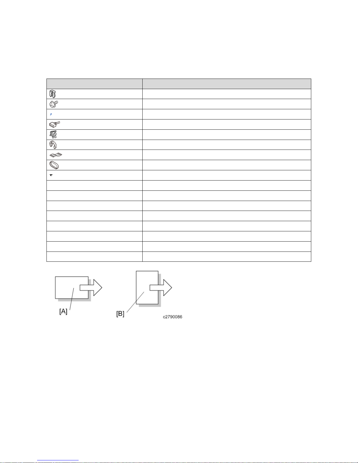
Symbols, Abbrevia tions
This manual uses several symbols and abbreviations. The meaning of those symbols and abbreviations are as
follows:
Symbol What it means
Clip ring
Screw
Screw: Blue
Connector
Clamp
E-ring
Flat Flexible Cable
Timing Belt
Hook (sensors)
SEF Short Edge Feed
LEF Long Edge Feed
K Black
C Cyan
M Magenta
Y Yellow
B/W, BW Black and White
FC Full color
[A] Short Edge Feed (SEF)
[B] Long Edge Feed (LEF)


1
Table of Contents
1. Replacement and Adjustment .............................................................................................................................3
Covers .................................................................................................................................................................... 3
Rear Upper Cover, Rear Lower Cover, Upper Cover ....................................................................................... 3
Front Cover, Front Left Side Cover .................................................................................................................. 5
Paper Guide Cover ............................................................................................................................................ 6
Paper Exit Cover ............................................................................................................................................... 8
Lower Tray ...................................................................................................................................................... 11
Proof Tray ....................................................................................................................................................... 11
Upper Tray ...................................................................................................................................................... 12
End Fence (SR4130) ....................................................................................................................................... 12
End Fence (SR4120) ....................................................................................................................................... 13
Paper Guide Unit ............................................................................................................................................. 14
Boards .................................................................................................................................................................. 17
Main Board ...................................................................................................................................................... 17
Main Motors ........................................................................................................................................................ 19
Corner Stapling Unit ....................................................................................................................................... 19
Paper Exit Gate Motor ..................................................................................................................................... 24
Leading Edge Guide Motor ............................................................................................................................. 24
Trailing Edge Pressure Plate Motor ................................................................................................................ 25
Stacking Roller Motor ..................................................................................................................................... 25
Feed Out Motor ............................................................................................................................................... 26
Jogger Motor ................................................................................................................................................... 26
Paper Guide Motor .......................................................................................................................................... 27
Sensors................................................................................................................................................................. 29
Shift Tray Paper Sensor ................................................................................................................................... 29
Trailing Edge Pressure Plate HP Sensor ......................................................................................................... 29
Stacking Roller HP Sensor .............................................................................................................................. 30
Staple Tray Paper Sensor ................................................................................................................................ 32
Paper Guide HP Sensor ................................................................................................................................... 33
Booklet Unit Motors ............................................................................................................................................ 35
Booklet Stapler Unit ........................................................................................................................................ 35
Press Fold Motor ............................................................................................................................................. 37
Booklet Jogger Motor ...................................................................................................................................... 40
Stapler Unit .......................................................................................................................................................... 41
Stapler Unit ..................................................................................................................................................... 41
Punch Unit ........................................................................................................................................................... 44
Fold Adjustments ................................................................................................................................................ 47

2
Flat Fold Roller Alignment ............................................................................................................................. 47
Adjusting the Folding Speed ........................................................................................................................... 49
Flat Fold Booklet Unit Home Position Adjustment ........................................................................................ 49
Paper Guide Unit ................................................................................................................................................. 52
Paper Exit Cover, Optional Output Jogger Unit .............................................................................................. 52
Paper Guide Unit ............................................................................................................................................. 57
Paper Guide Unit Sensor ................................................................................................................................. 60
Paper Guide Motor .......................................................................................................................................... 61
2. Detailed Descriptions .......................................................................................................................................63
Overview ............................................................................................................................................................. 63
Layout ............................................................................................................................................................. 63
Operation Details ................................................................................................................................................. 71
Shift Operation (Shift Transport) .................................................................................................................... 71
Pre-stack Operation (In Corner Stapling) ........................................................................................................ 71
Pre-stack Operation (Booklet Stapling)........................................................................................................... 72
Upper Tray Shift Drive / Limit Sensor / Full Sensor ...................................................................................... 73
Pull-in Roller / Paper Stack Holder ................................................................................................................. 75
Corner Stapling ............................................................................................................................................... 77
Saddle Stapling (Booklet Stapling) ................................................................................................................. 82
1.Replacement and Adjustment
3
1. Replacement and Adjustment
Covers
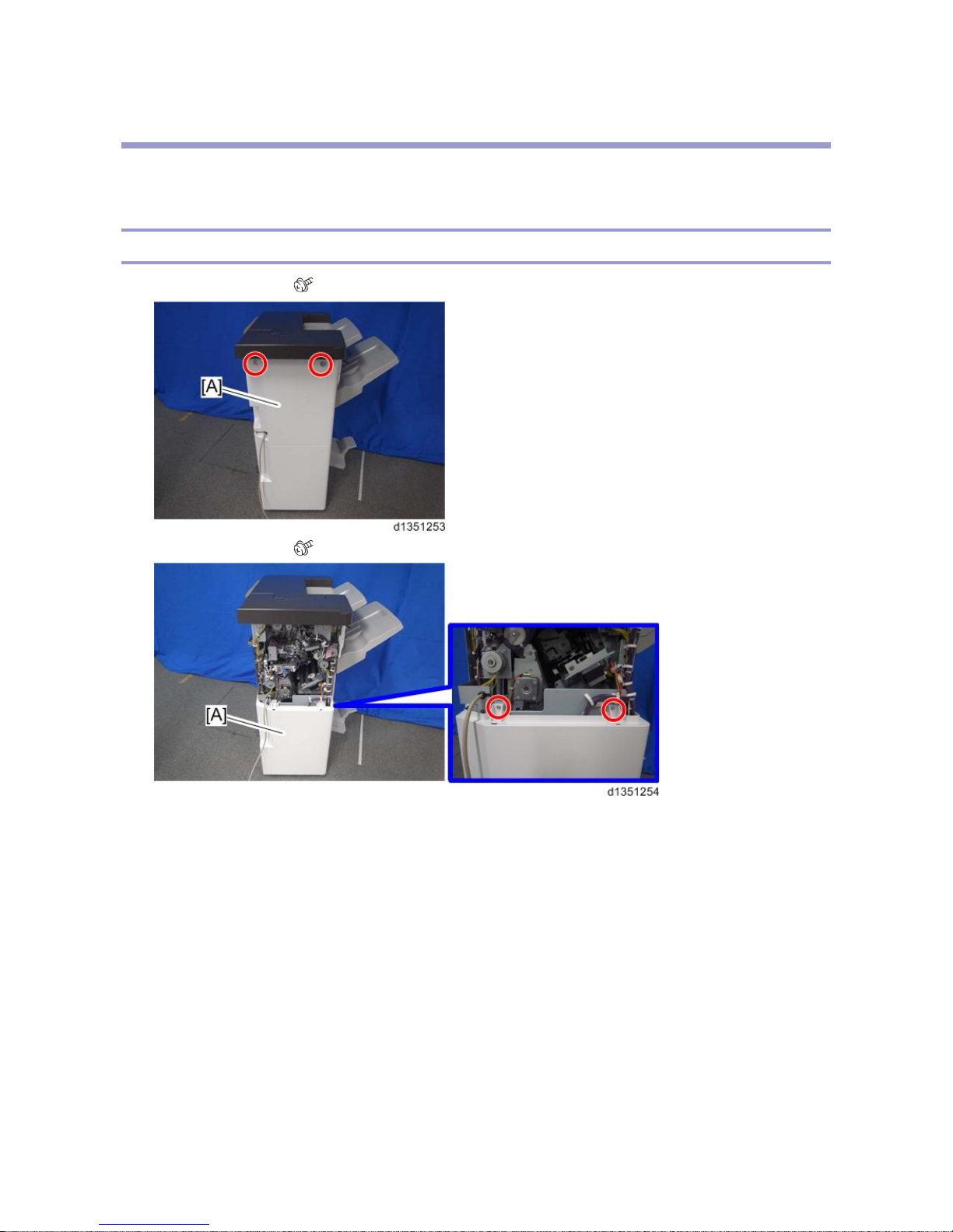
Rear Upper Cover, Rear Lower Cover, Upper Cover
1. Rear upper cover [A] ( x 2)
2. Rear lower cover [A] ( x 2)
1.Replacement and Adjustment
4
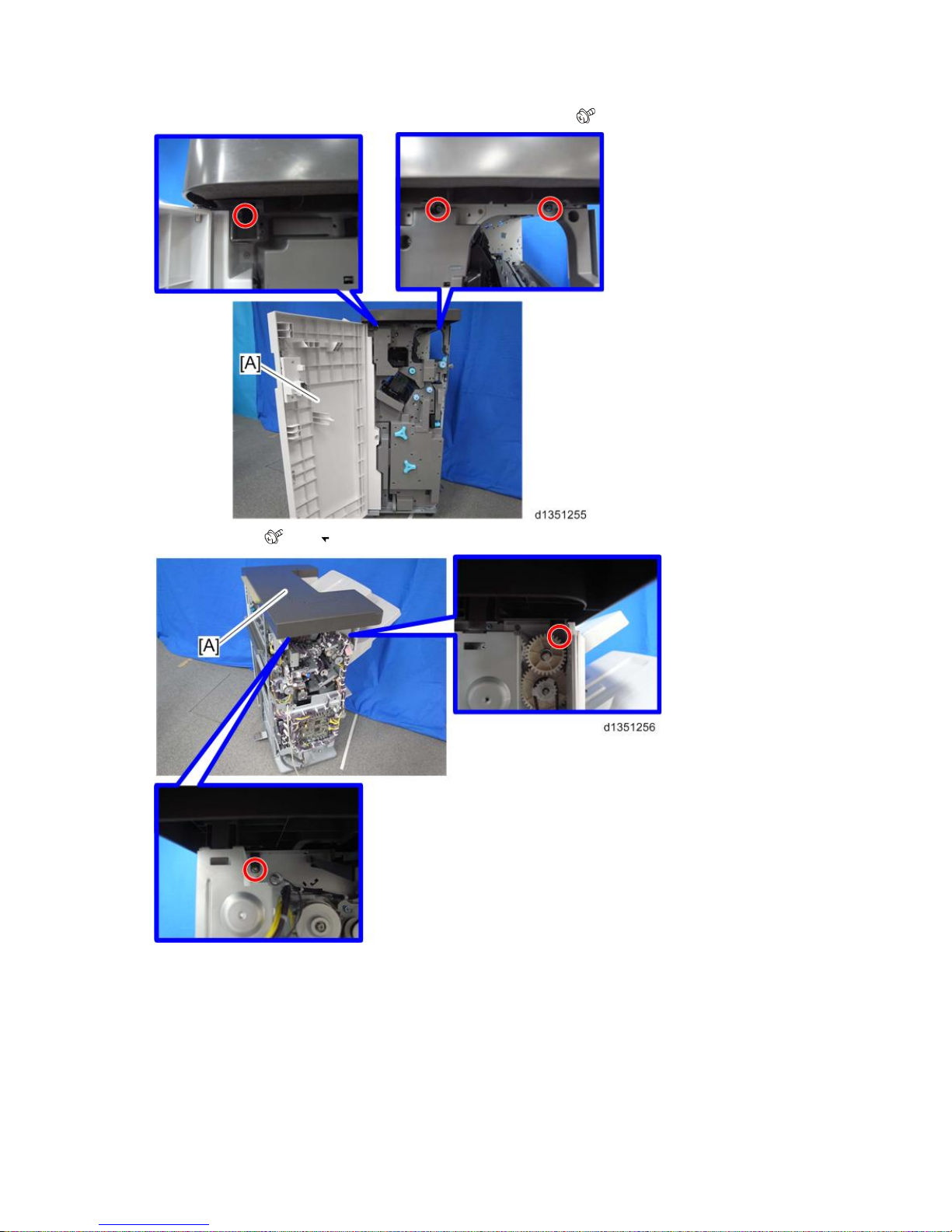
3. Open the front door [A], and remove the screws of the upper cover. ( x 5)
4. Upper cover [A] ( x 2, x 2)
1.Replacement and Adjustment
5
5. Check the positions of the bosses and hooks before removing the upper cover.
6. When the upper cover is re-attached, tighten the screws on the right side in the order shown below: 1 > 2 > 3.
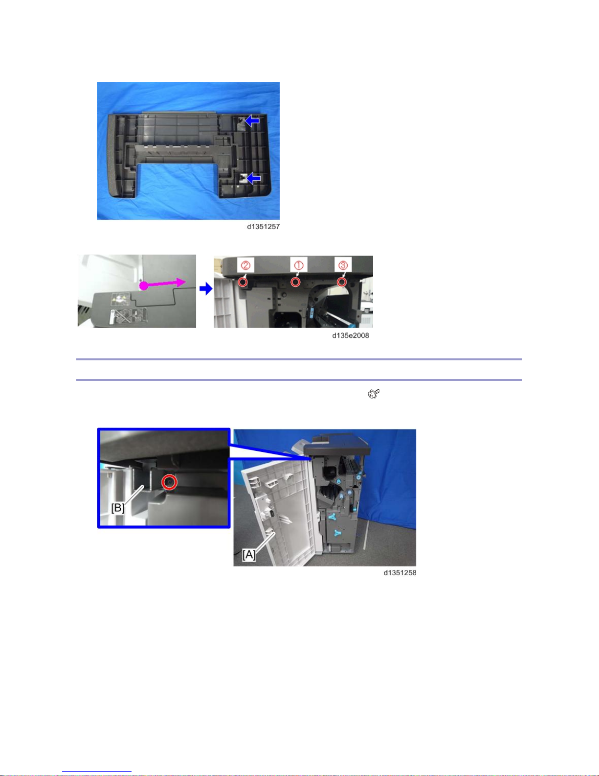
Front Cover, Front Left Side Cover
1. Open the front door [A], and then remove the front door bracket [B]. ( x 1)
2. Front door [A]
1.Replacement and Adjustment
6
3. Front left side cover [A] ( x 2)
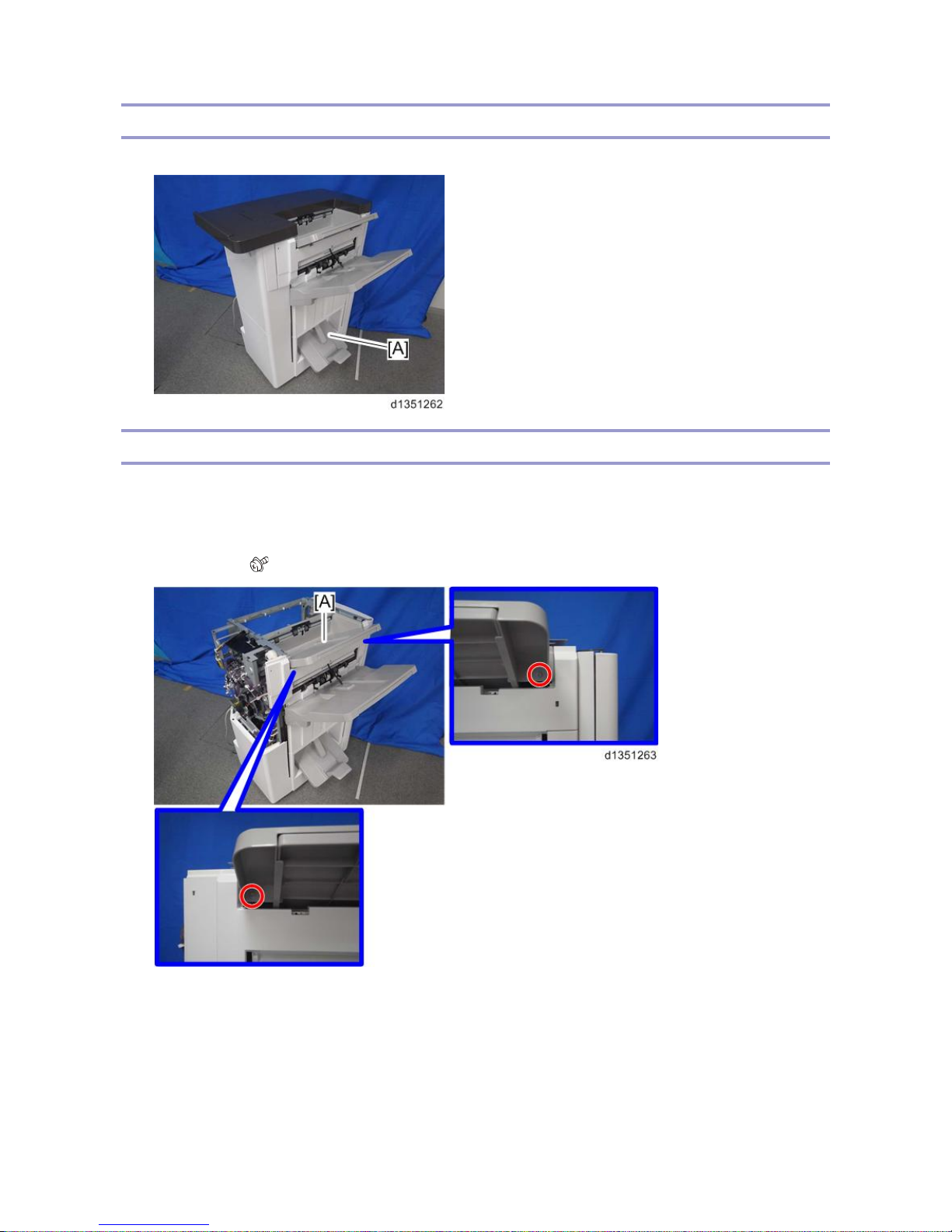
Paper Guide Cover
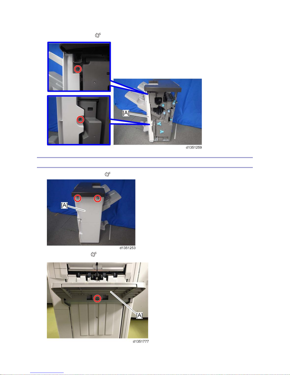
1. Remove rear upper cover [A] ( x1).
2. Remove shift tray [A] ( x1).
1.Replacement and Adjustment
7
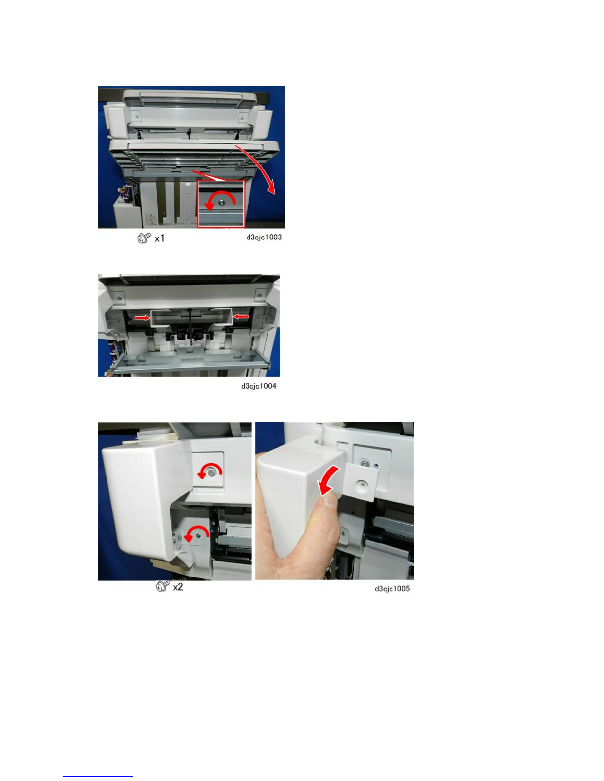
3. Push the guides in to the center.
4. Remove rear paper guide cover [A] ( x1).
5. Remove front paper guide cover [A] ( x2).
1.Replacement and Adjustment
8
6. Remove paper guide cover [A] screws ( x2).
7. Disconnect the front tab, and then remove the cover.
Paper Exit Cover
1. Disconnect the finisher from the main frame.
2. Remove the rear cover.
1.Replacement and Adjustment
9
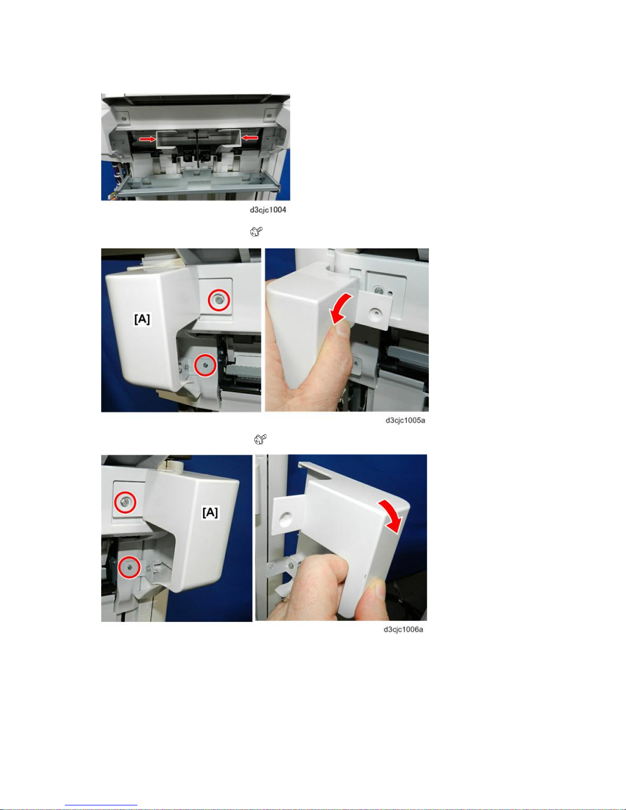
3. Remove the shift tray.
4. Push the paper guides to the center.
5. Remove the rear paper guide cover.

1.Replacement and Adjustment
10
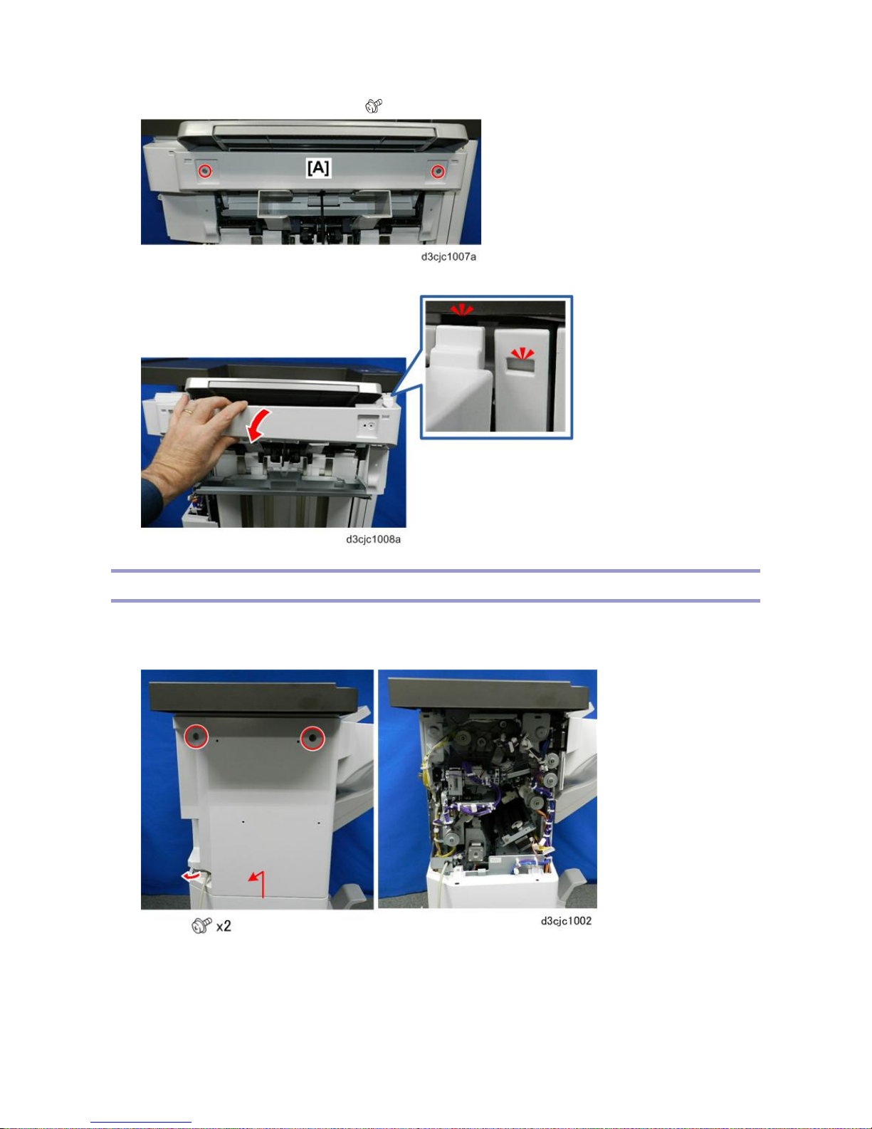
6. Remove the front paper guide cover.
7. Disconnect the main paper guide cover.
8. Carefully, separate the front tabs at [A], and then remove the main paper guide cover [B].
1.Replacement and Adjustment
11
Lower Tray
1. Lower tray [A]
Proof Tray
1. Remove the following covers. Rear Upper Cover, Rear Lower Cover, Upper Cover
• Rear upper cover
• Upper cover
2. Proof tray [A] ( x 2)
1.Replacement and Adjustment
12
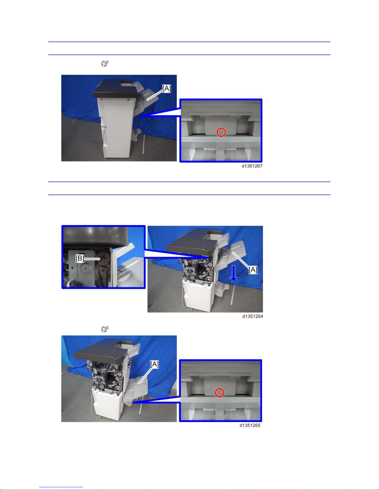
Upper Tray
1. Upper tray [A] ( x 1)
End Fence (SR4130)
1. Remove the rear upper cover. Rear Upper Cover, Rear Lower Cover, Upper Cover
2. Support the upper tray [A] with your right hand, and then pull gear [B] toward you to release.
3. Upper tray [A] ( x 1)
4. Lower Tray (Lower Tray)
1.Replacement and Adjustment
13
5. End fence [A] ( x 2)
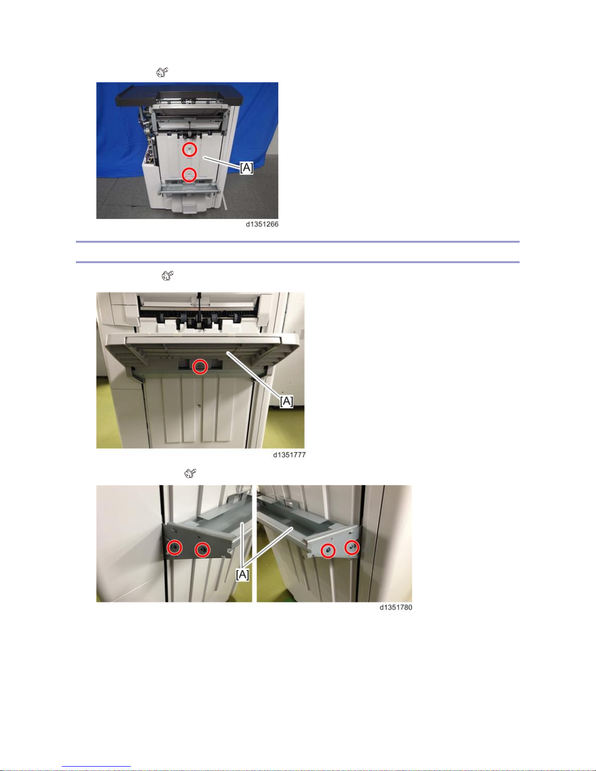
End Fence (SR4120)
1. Upper Tray [A] ( x 1)
2. Shift tray bracket [A] ( x 4)
1.Replacement and Adjustment
14
3. End fence [A] ( x 3)
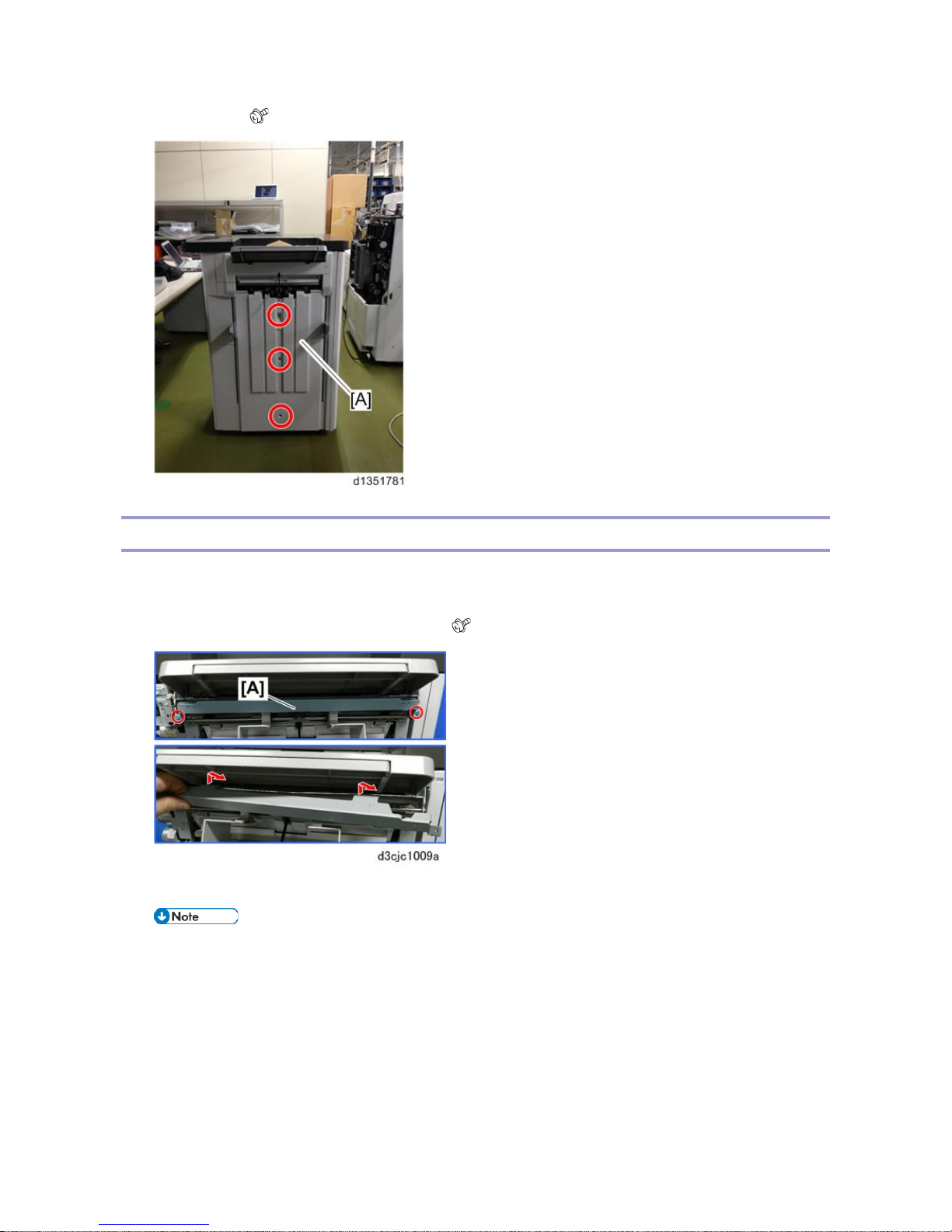
Paper Guide Unit
1. Remove the paper exit guide.
2. If the Output Jogger Unit Type M25 (option) unit is installed, remove it.
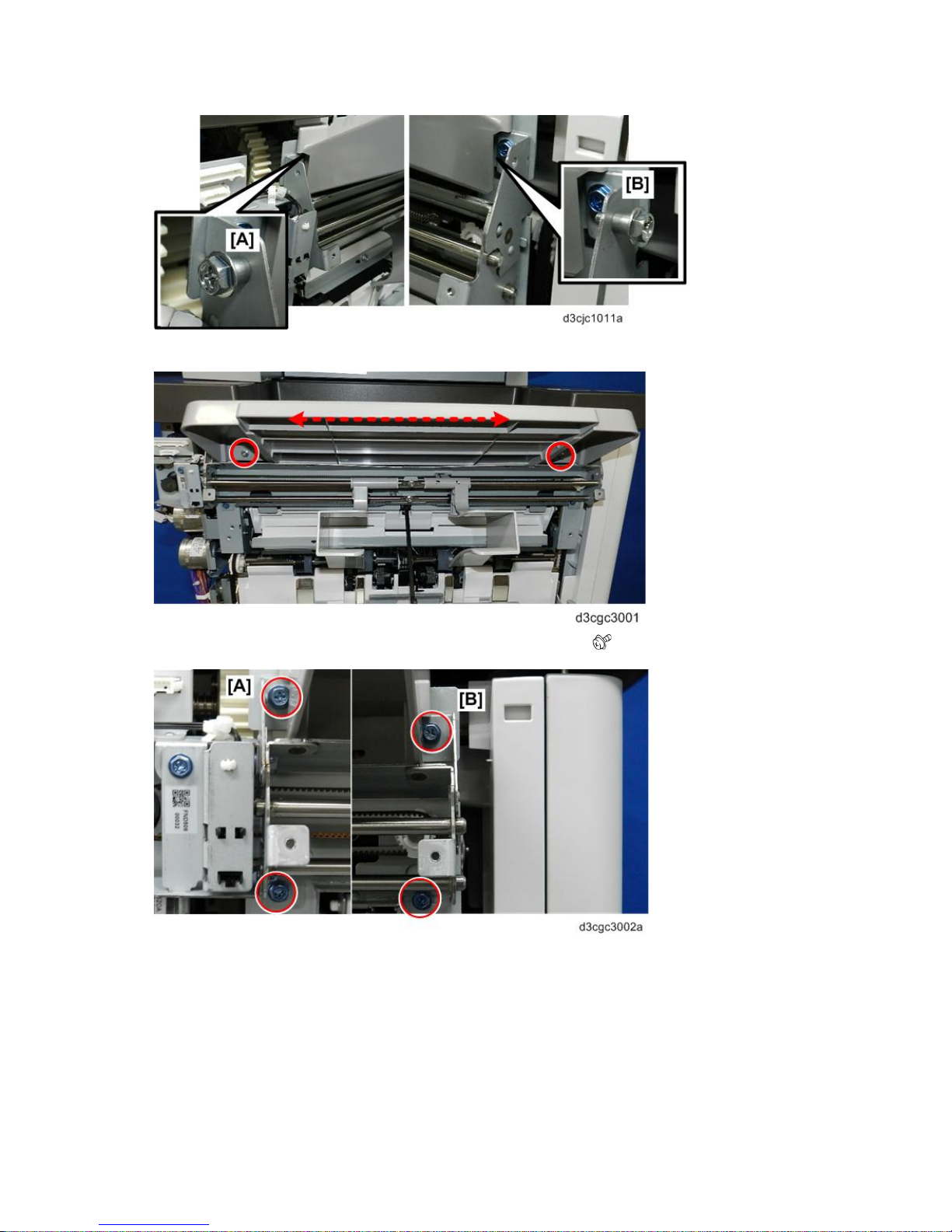
3. Remove paper guide cover support bracket [A] ( x2).
4. At the front and back remove the shoulder screws [A] and [B] of the output jogger unit if it was installed.
• Removing the jogger unit makes it easier to access the paper guide unit fastening screws. Do not
lose these screws.
1.Replacement and Adjustment
15
5. Loosen the proof tray screws temporarily to make it easier to reach the paper guide fastening screws.
6. Remove the paper guide fastening screws at the front [A] and rear [B] ( x4).
1.Replacement and Adjustment
16
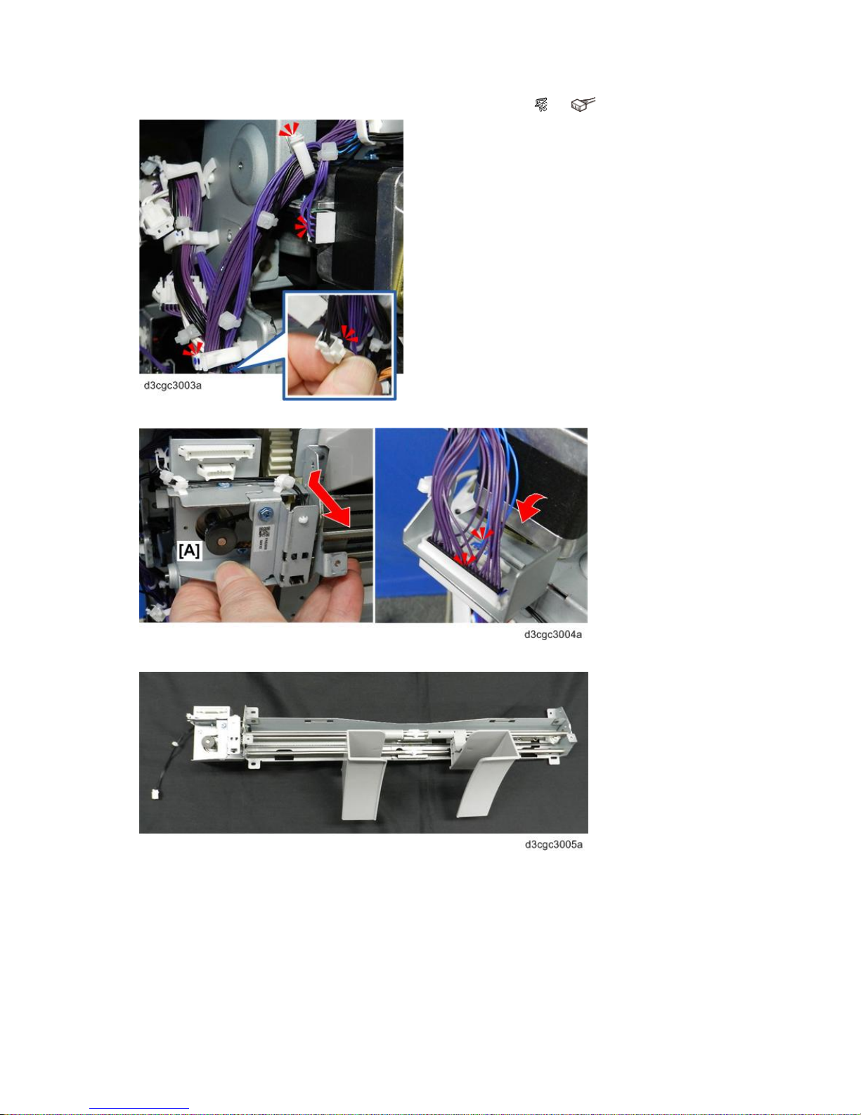
7. At the rear, open the clamp, and then disconnect the motor and sensor ( x2, x2).
8. Tilt the paper guide unit toward you, and then disconnect the harness of motor bracket [A].
9. Remove the paper guide unit and place on a flat, clean surface.
1.Replacement and Adjustment
17
Boards
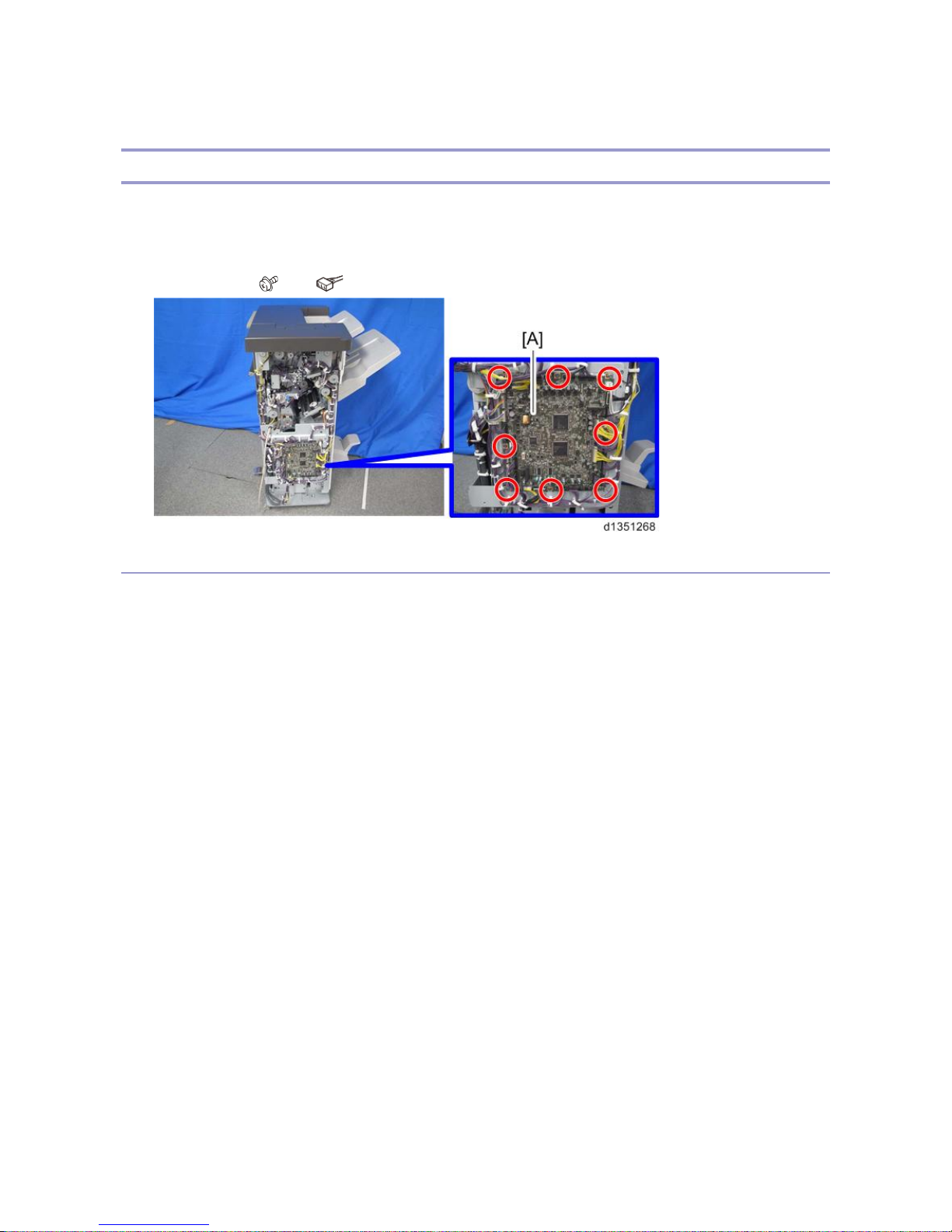
Main Board
1. Remove the following covers. Rear Upper Cover, Rear Lower Cover, Upper Cover
• Rear upper cover
• Rear lower cover
2. Main board [A] ( x 4, x All)
When replacing the main board
This board has two blocks of DIP switches. When you reinstall the main board, follow the procedure below
regarding the dip switch settings.
1. Check the settings of dip switch [A] on the old main board.
2. Replace the main board.
3. Change the settings of dip switch [A] on the new main board to match the settings on the old main board.
4. Make sure the switches of dip switch [B] on the new main board are all OFF.

1.Replacement and Adjustment
18
5. When replacing the control board, remove EEPROM [C] from the old board and install it on the new board.
6. Locate the seal [A] attached near the right corner of the board.
7. Go into the SP mode, open these SP codes, and then enter the numbers you see on the seal.
• SP6121-001 NV Adj. Data: Jog Position: Factory Adj.
• SP6121-002 NV Adj. Data: Fold Position: Factory Adj.
1.Replacement and Adjustment
19
Main Motors
Corner Stapling Unit
1. Remove the following covers. Covers
• Front door
• Front left side cover
• End fence
• Rear upper cover
• Rear lower cover
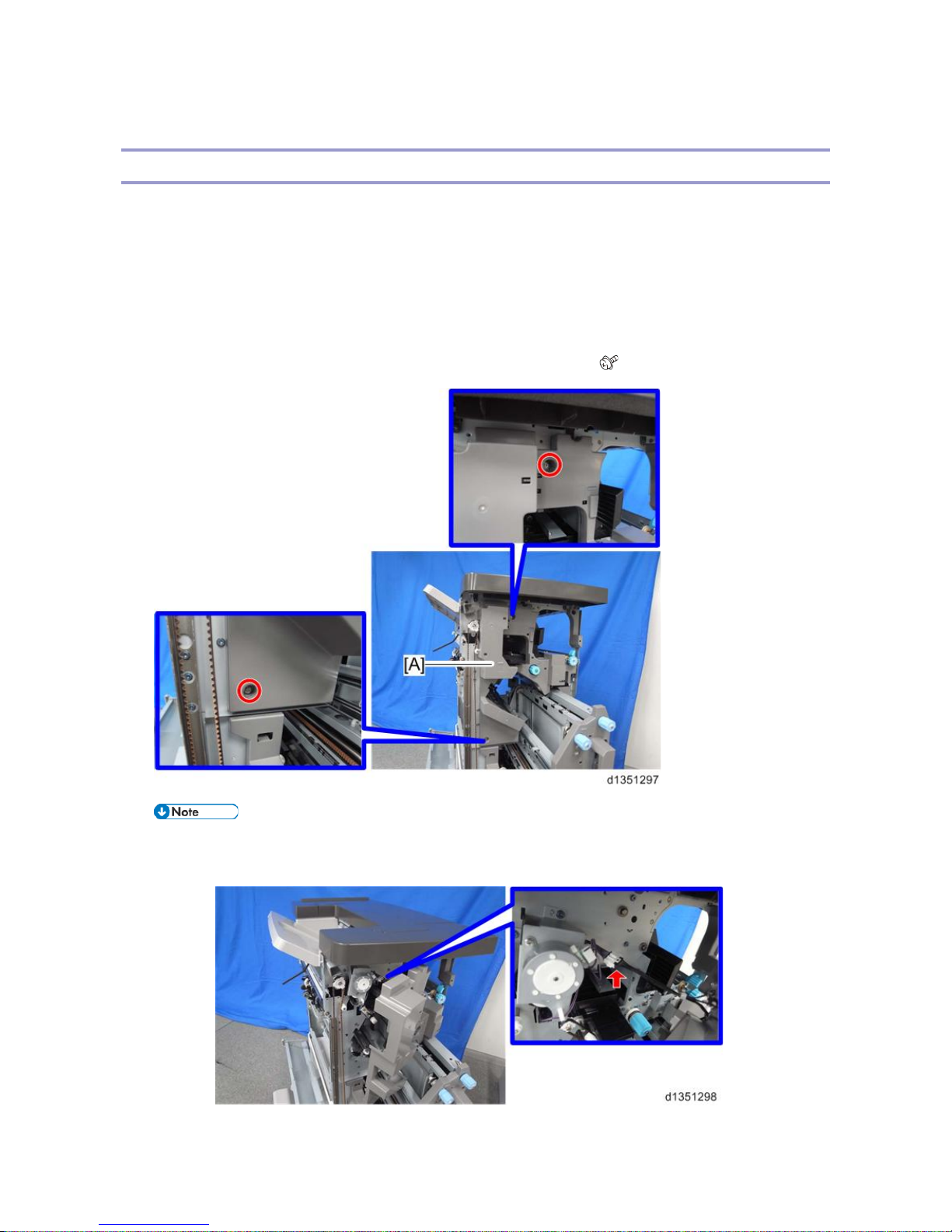
2. Pull out the booklet stapler unit, and remove the inner upper cover [A]. ( x 2)
• Disconnect the harness from the back side of the inner upper cover when you remove the inner
upper cover.
1.Replacement and Adjustment
20
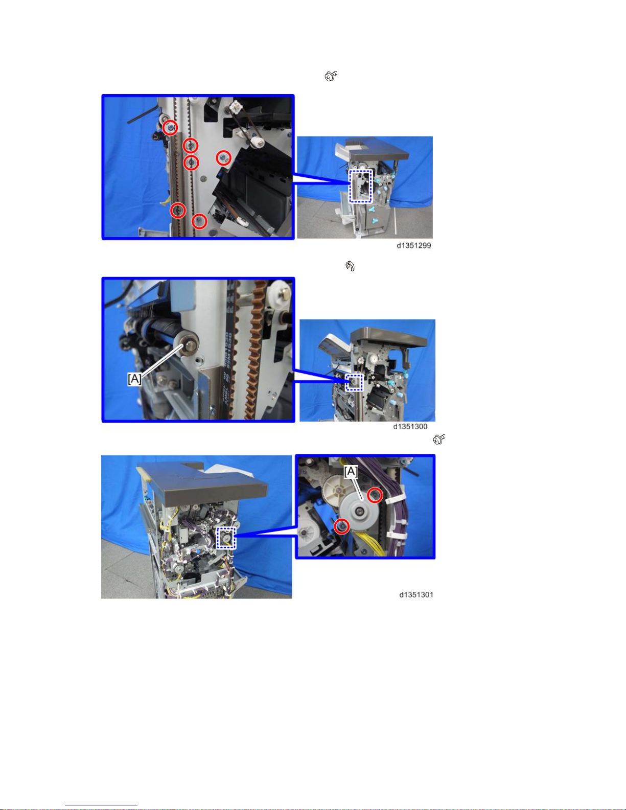
3. Remove the screws from the front side of the finisher. ( x 6)
4. Remove the bushing [A] from the front side of the finisher. ( x1)
5. Remove the pressure release motor bracket [A] from the rear side of the finisher. ( x 2)
1.Replacement and Adjustment
21
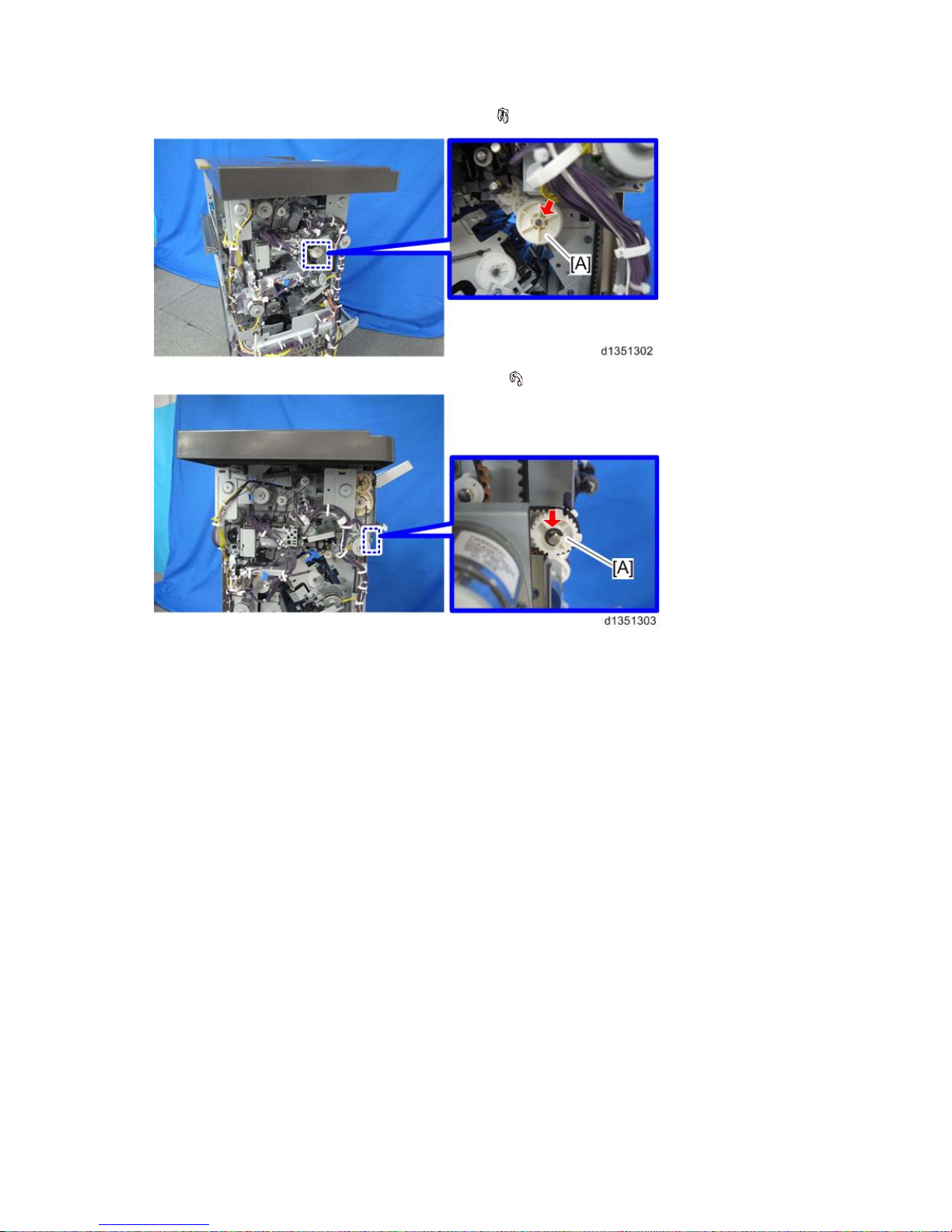
6. Remove the gear [A] from the rear side of the finisher. ( x 1)
7. Remove the pulley [A] from the rear side of the finisher. ( x 1)
1.Replacement and Adjustment
22
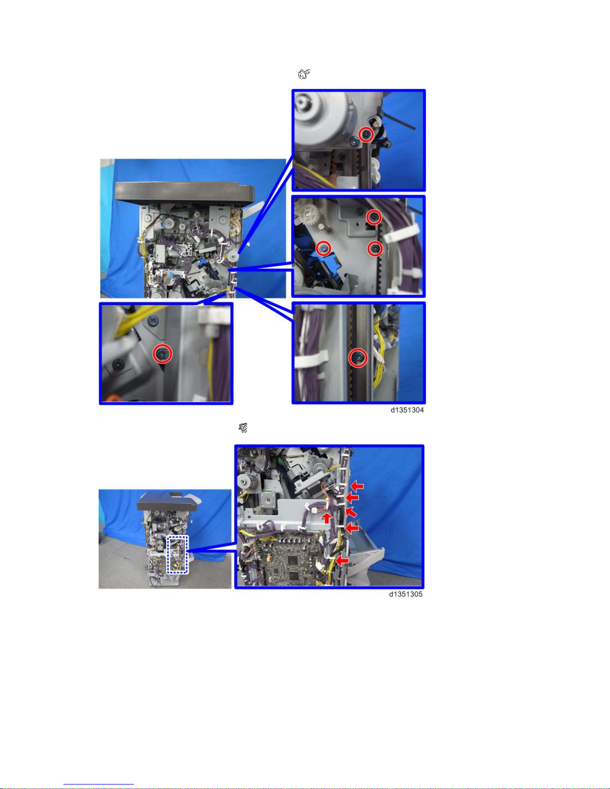
8. Remove screws from the rear side of the finisher. ( x 6)
9. Remove the clamps shown below. ( x 6)
1.Replacement and Adjustment
23
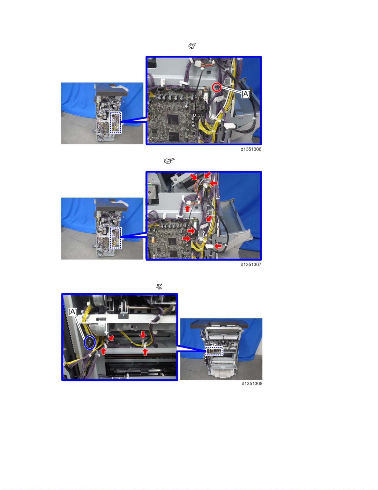
10. Disconnect the ground wire [A] of the main board. ( x 1)
11. Disconnect the connectors shown below. ( x 8)
12. Pull out the harnesses disconnected in step 11 to the right side of the finisher through the hole [A].
13. Remove the harness from the clamps. ( x 4)
1.Replacement and Adjustment
24
14. Remove the corner stapling unit [A] from between the front and left plates.
Paper Exit Gate Motor
1. Corner stapling unit (Corner Stapling Unit)
2. Stapler bracket [A] ( x 3, x 1)
3. Paper exit gate motor [A] ( x 2, x 1)
Leading Edge Guide Motor
1. Corner stapling unit (Corner Stapling Unit)

1.Replacement and Adjustment
25
2. Stapler bracket [A] ( x 3, x 1)
3. Leading edge guide motor [A] ( x 2, x 1)
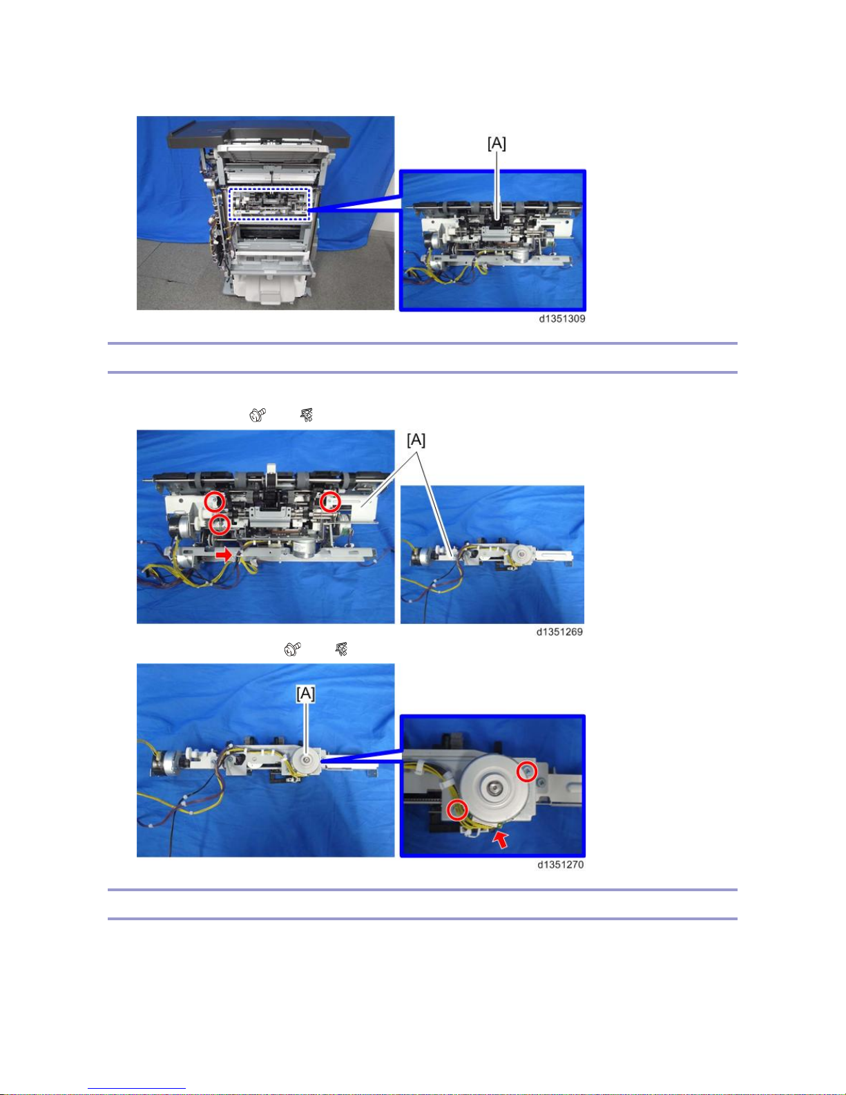
Trailing Edge Pressure Plate Motor
1. Corner stapling unit (Corner Stapling Unit)
2. Trailing edge pressure plate motor [A] ( x 2, x 1)
Stacking Roller Motor
1. Rear upper cover (Covers)
 Loading...