

Ricoh SR4110 Field Service Manual

Finisher SR4110
Machine Code: D707
Field Service Manual
Ver 1.01
Latest Release: Jan, 2017
Initial Release : Oc t, 201 6
Copyright (c) 2016 - 2017 Ricoh Co.,Ltd.

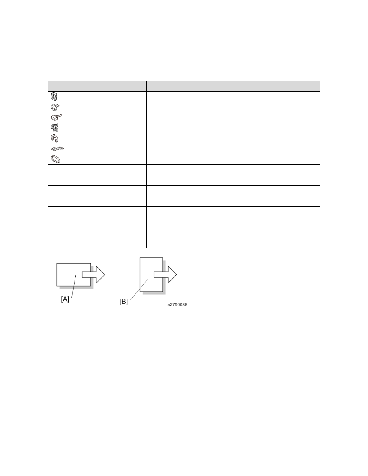
Symbols, Abbrevia tions
This manual uses several symbols and abbreviations. The meaning of those symbols and abbreviations are as
follows:
Symbol What it means
Clip ring
Screw
Connector
Clamp
E-ring
Flat Flexible Cable
Timing Belt
SEF Short Edge Feed
LEF Long Edge Feed
K Black
C Cyan
M Magenta
Y Yellow
B/W, BW Black and White
FC Full color
[A] Short Edge Feed (SEF)
[B] Long Edge Feed (LEF)


1
Table of Contents
1. Detailed Descriptions .........................................................................................................................................3
Mechanism Descriptions ....................................................................................................................................... 3
Fuse List ............................................................................................................................................................ 3
Component Layout ............................................................................................................................................ 5
Electrical Components ...................................................................................................................................... 6
Drive Layout ..................................................................................................................................................... 9
Mechanism Details .............................................................................................................................................. 11
Inverter ............................................................................................................................................................ 11
Shift Tray ........................................................................................................................................................ 12
Pre-stack .......................................................................................................................................................... 14
Staple Tray Jogger ........................................................................................................................................... 15
Stapling ........................................................................................................................................................... 17
Punch (2-hole Punch Unit) .............................................................................................................................. 21
Jam Detection .................................................................................................................................................. 23
DIP SW ........................................................................................................................................................... 24
2. Replacement and Adjustment ...........................................................................................................................25
Covers .................................................................................................................................................................. 25
Front Door, Left Inner Cover, Inner Cover ..................................................................................................... 25
Inner Cover ...................................................................................................................................................... 26
Side Table and Upper Tray ............................................................................................................................. 26
Left Covers, Rear Cover, Top Cover, Shift Cover .......................................................................................... 27
Jogger Unit Cover ........................................................................................................................................... 28
Rollers ................................................................................................................................................................. 29
Drag Roller ...................................................................................................................................................... 29
Positioning Roller ............................................................................................................................................ 29
Alignment Brush Roller .................................................................................................................................. 30
Jogger Fence .................................................................................................................................................... 31
Sensors................................................................................................................................................................. 33
Paper Height Sensors ...................................................................................................................................... 33
Exit Guide HP Sensor ..................................................................................................................................... 33
Upper Tray Full and Exit Sensors ................................................................................................................... 34
Shift Tray Exit Sensor ..................................................................................................................................... 35
Main Board, Pre-Stack Paper Sensor .............................................................................................................. 36
Staple Trimmings Hopper Full Sensor ............................................................................................................ 37
Stapler Rotation HP and Stapler Return Sensors ............................................................................................ 38
Stapler ............................................................................................................................................................. 39
Shift Tray ............................................................................................................................................................. 41

2
Shift Tray Exit, Shift Tray Lift Motor ............................................................................................................. 41
Shift Tray Lift Motor ....................................................................................................................................... 41
Drag Roller, Drag Drive Motors, Drag Drive HP Sensor ............................................................................... 42
Shift Motor and Sensors .................................................................................................................................. 44
Jogger Top Fence Motor ................................................................................................................................. 45
Jogger Unit ...................................................................................................................................................... 45
Jogger Bottom Fence Motor ............................................................................................................................ 46
Punch Unit ........................................................................................................................................................... 47
Punch Position Adjustment ............................................................................................................................. 47
Motors ................................................................................................................................................................. 48
Transport Motors, Exit Guide Motor............................................................................................................... 48
Upper Tray Motors .......................................................................................................................................... 49
Pre-Stack Motors ............................................................................................................................................. 50
Punch Motor .................................................................................................................................................... 52
Staple Motors .................................................................................................................................................. 53
3. Service Tables ..................................................................................................................................................54
Dip Switches ........................................................................................................................................................ 54
Test Points ........................................................................................................................................................... 55
Fuses .................................................................................................................................................................... 56

1.Detailed Descriptions
3
1. Detailed Descriptions
Mechanism Descriptions
Fuse List
Fuse
Name
Output
Connector
Capacity Voltage Parts No. Affected Part Remarks Removability
FU100 CN120
CN120
CN113
CN121
CN120
CN122
CN123
CN123
CN124
CN146
CN134
CN125
CN128
CN126
CN126
CN127
CN127
CN128
CN129
CN129
CN130
CN130
CN131
CN125
CN133
CN118
CN119
CN610
CN710
5A 250V 11071006 M1: Shift Paper
Output M
M2: Tray
Upper/Lower M
M3: Paper Exit
Open/Close M
M4: Staple Paper
Exit M
M5: Proof Paper
Exit M
M6: Shift M
M7: Proof Switch
M
M8 Staple Switch
M
M9: Press Tuck
Switch M
M10: Press Tuck
Transfer M
M11: Press Tuck
Paw Release M
M12: Beat Drive
M
M13: Beat
Transfer M
M14 Return
Drive M
M15: Return
Drive M
M16: Jogger M
Full Load
Punch: Punch
Board
Shift Jogger
part M: Shift
Jogger Board
Yes

1.Detailed Descriptions
4
CN710
CN132
M17: Release M
M18: Holder M
M18: Holder
Front M
M20: Holder
Rear M
M21: Stapler
Front/Rear M
M22: Stapler
Opposite Corner
M
M23: Staple M
M24: Leading
Edge Stopper M
M25: Movable
Fence M
M27: Upper
Transfer M
M28: Lower
Transfer M
M29: Punch M
M30: Shift
Jogger M
M31: Shift
Jogger Retracted
M
SOL1: Shooter
Open/Close SOL
1.Detailed Descriptions
5
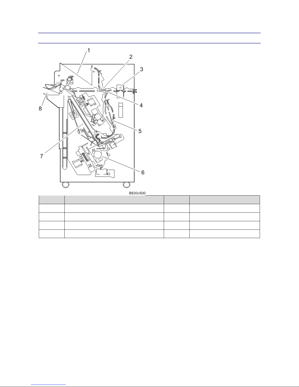
Component Layout
No. Description No. Description
1 Proof Tray 5 Pre-stack Tray
2 Proof Junction Gate 6 Stapler
3 Punch Unit 7 Stapler Unit
4 Stapler Junction Gate 8 Shift Tray
• Inverter
Distributes paper to the proof tray, the shift mode, or the staple mode. The destination varies depending on
whether the paper is sorted or stapled, or not.
• Pre Stack Tray
When stapling two or more sheets, the 1st to 3rd sheets wait in the pre stack tray and are then transferred
together to the stapler. The following sheets (4th, 5th…) are sent to the staple tray two by two. This method
contributes to reducing waiting time to enhance productivity for stapling.
Supported Sizes: A4 SEF, B5 SEF, LT SEF
• Proof Tray
The tray to which paper is output when the sort mode or the staple mode isn’t chosen
• Shift Tray
Moves up and down depending on the number of outputs printed, and side-to-side shift in sort mode
• Staple Tray Jogger
With the paper leading edge stopper (supports only the sizes that go in the pre-stack tray), the alignment
1.Detailed Descriptions
6
brush roller, the positioning roller and the jogger fence, the staple tray jogger tidies the edges of the stack
before stapling.
• Punch Unit
Punches and makes holes with the punch motor.
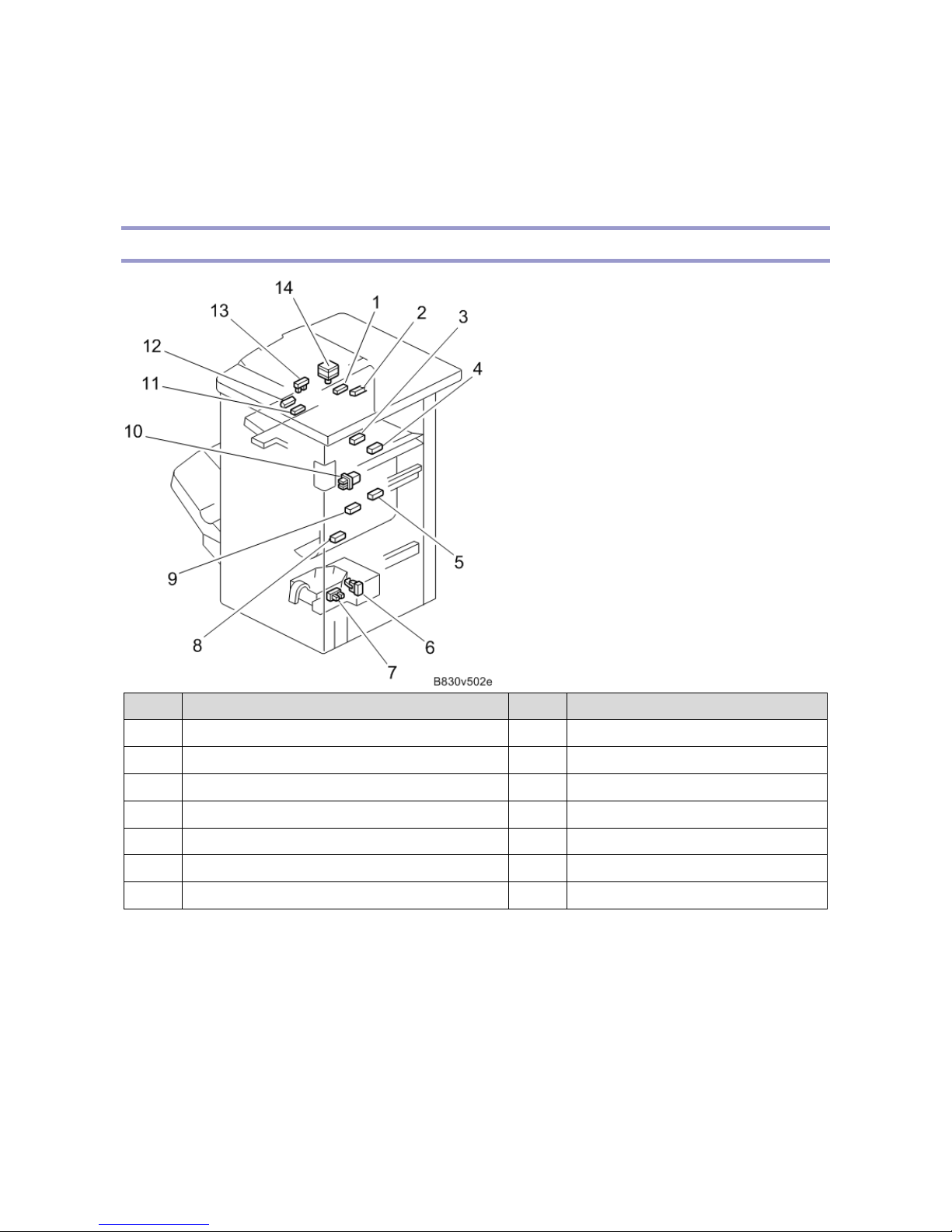
Electrical Components
No. Description No. Description
1 Proof Tray Exit Sensor 8 Stapler Exit Sensor
2 Proof Tray Full Sensor 9 Staple Tray Paper Sensor
3 Jam Sensor 10 Interlock Switch
4 Entrance Sensor 11 Shift Tray Paper Sensor
5 Pre-stack Sensor 12 Staple Paper Sensor
6 Used Staple Hopper Set Sensor 13 Exit Open/close Sensor
7 Used Staple Hopper Full Sensor 14 Exit Open/close Motor

1.Detailed Descriptions
7
No. Description No. Description
1 Leading Edge Stopper Motor 14 Paper Hold Front Motor
2 Positioning Roller Motor 15 Used Staple Disposing Solenoid
3 Drag-in Motor 16 Stapler Rotation Motor
4 Drag-in HP Sensor 17 Stapler Movement HP Sensor
5 Stapler Front/rear Motor 18 Stapler Rotation Sensor
6 Paper Hold Center Motor 19 Feed Out Belt HP Sensor
7 Paper Hold HP Sensor 20 Staple Tray Paper Sensor
8 Paper Hold Rear HP Sensor 21 Bottom Fence HP Sensor
9 Paper Hold Rear Motor 22 Bottom Fence Motor
10 Paper Hold Front HP Sensor 23 Jogger HP Sensor
11 Staple Hammer HP Sensor 24 Jogger Motor
12 Staple Cartridge Set Sensor 25 Feed Out Belt Motor
13 Staple Motor 26 Leading Edge Stopper HP Sensor
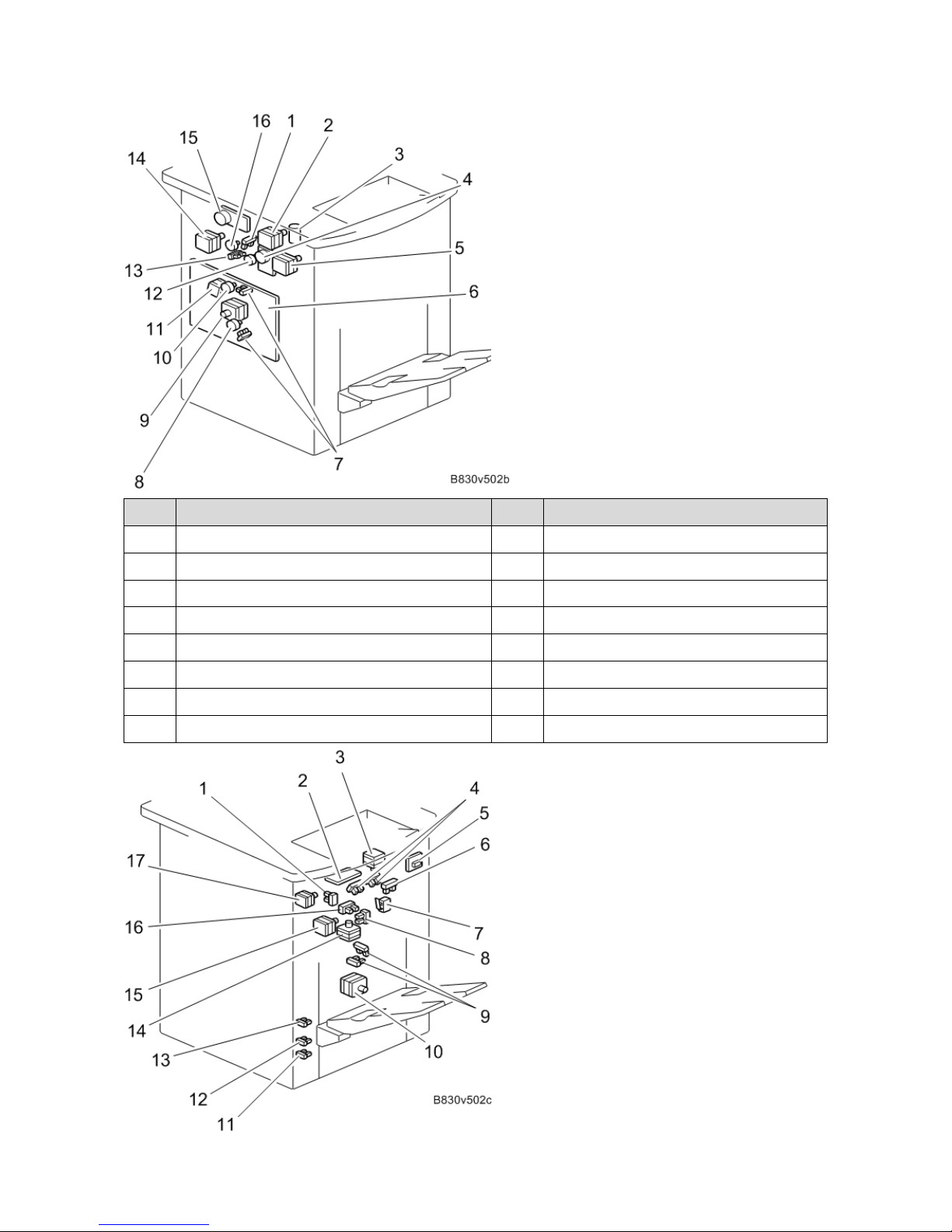
1.Detailed Descriptions
8
No. Description No. Description
1 Stapler Junction Gate HP Se ns or 9 Transport Motor
2 Proof Exit Motor 10 Pre-stack Junction Gate
3 Tray Upper/lower Motor 11 Vertical Transport Motor
4 Lower Transport Motor 12 Proof Junction Gate Motor
5 Shift Exit Motor 13 Proof Junction Gate HP Sensor
6 Main Controller Board 14 Punch Unit Motor
7 Pre-stack Junction Gate HP Sensor 15 Upper Transport Motor
8 Pre-stack Junction Gate Motor 16 Stapler Junction Gate Motor
1.Detailed Descriptions
9
No. Description No. Description
1 Jogger HP Sensor 10 Shift Motor
2 PCB 11 Tray Lower Limit Sensor
3 Jogger Motor 12 Tray Near-limit Sensor
4 Shift Paper Sensor 13 Tray Lower Sensor
5 PCB 14 Drag-in Drive Motor
6 Staple Paper Sensor 15 Drag-in Transport Motor
7 Emergency Stop Switch 16 Paper Sensor
8 Drag-in Drive HP Sensor 17 Jogger Motor
9 Shift Tray HP Sensor
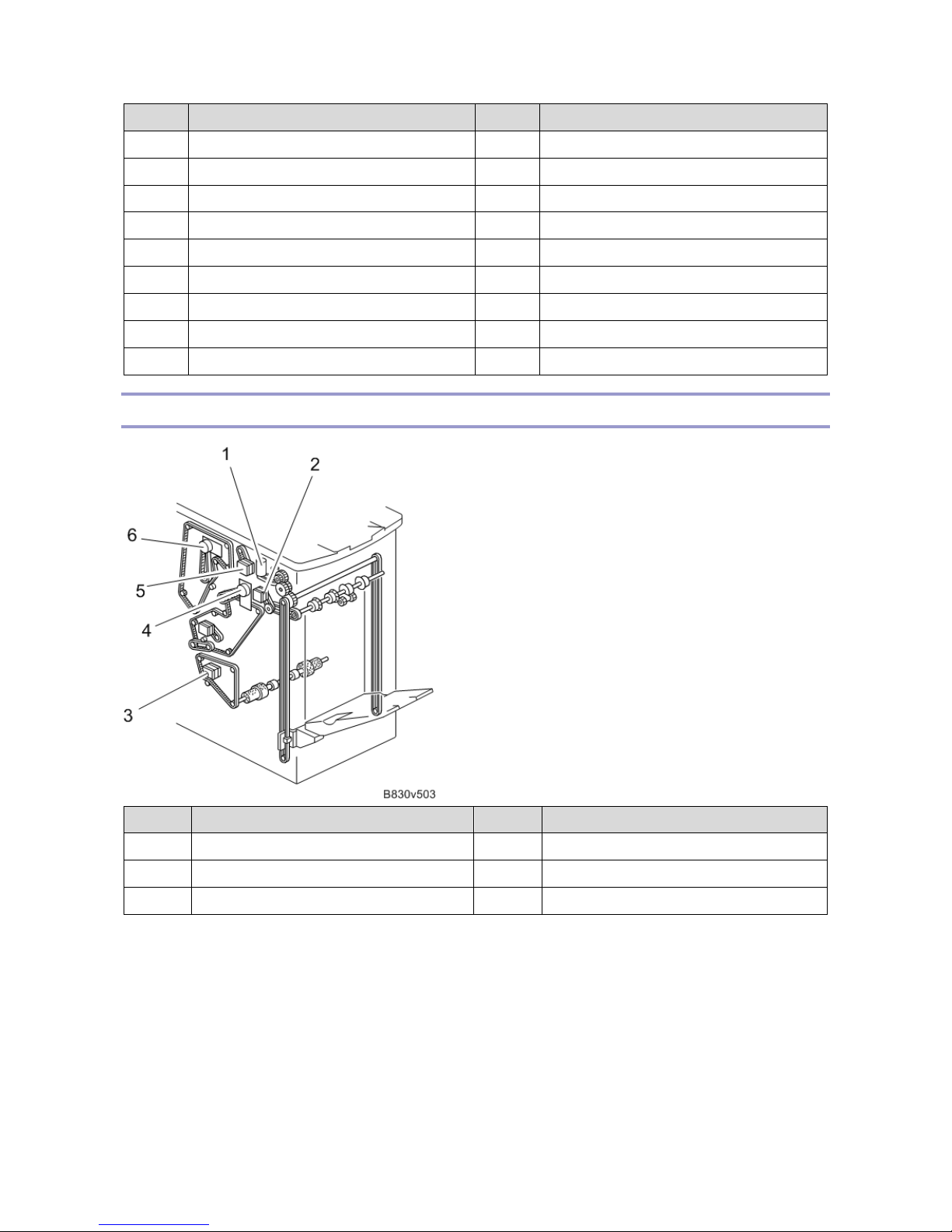
Drive Layout
No. Description No. Description
1 Tray Shift Motor 4 Lower Transport Motor
2 Shift Exit Motor 5 Proof Exit Motor
3 Staple Transport Motor 6 Upper Transport Motor
1.Detailed Descriptions
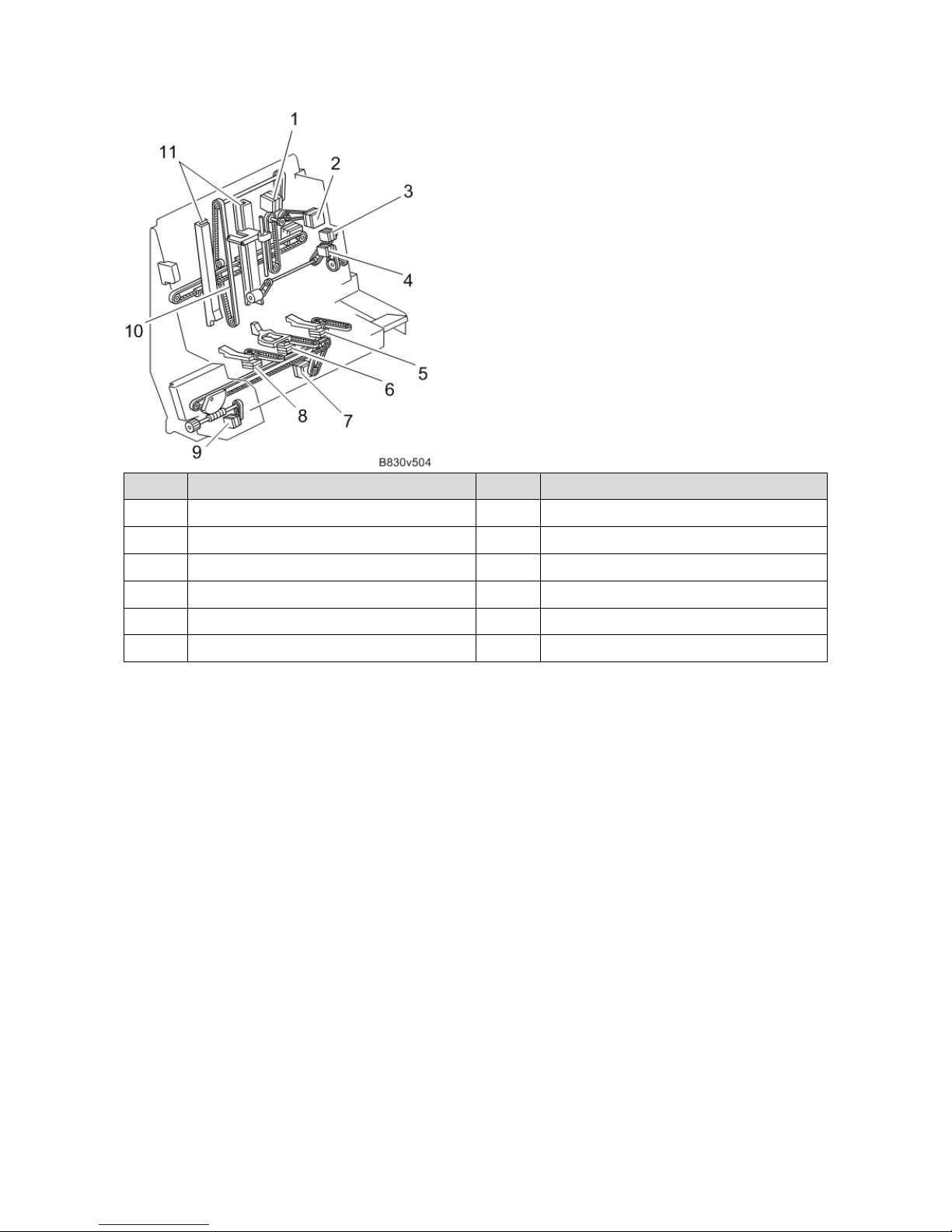
10
No. Description No. Description
1 Feed Out Motor 7 Stapler Front/Rear Motor
2 Jogger Motor 8 Paper Hold Front Motor
3 Positioning Roller Motor 9 Staple Rotation Motor
4 Drag-in Motor 10 Feed Out Belt
5 Paper Hold Rear Sensor 11 Jogger Fence
6 Paper Hold Center Motor
1.Detailed Descriptions
11
Mechanism Details
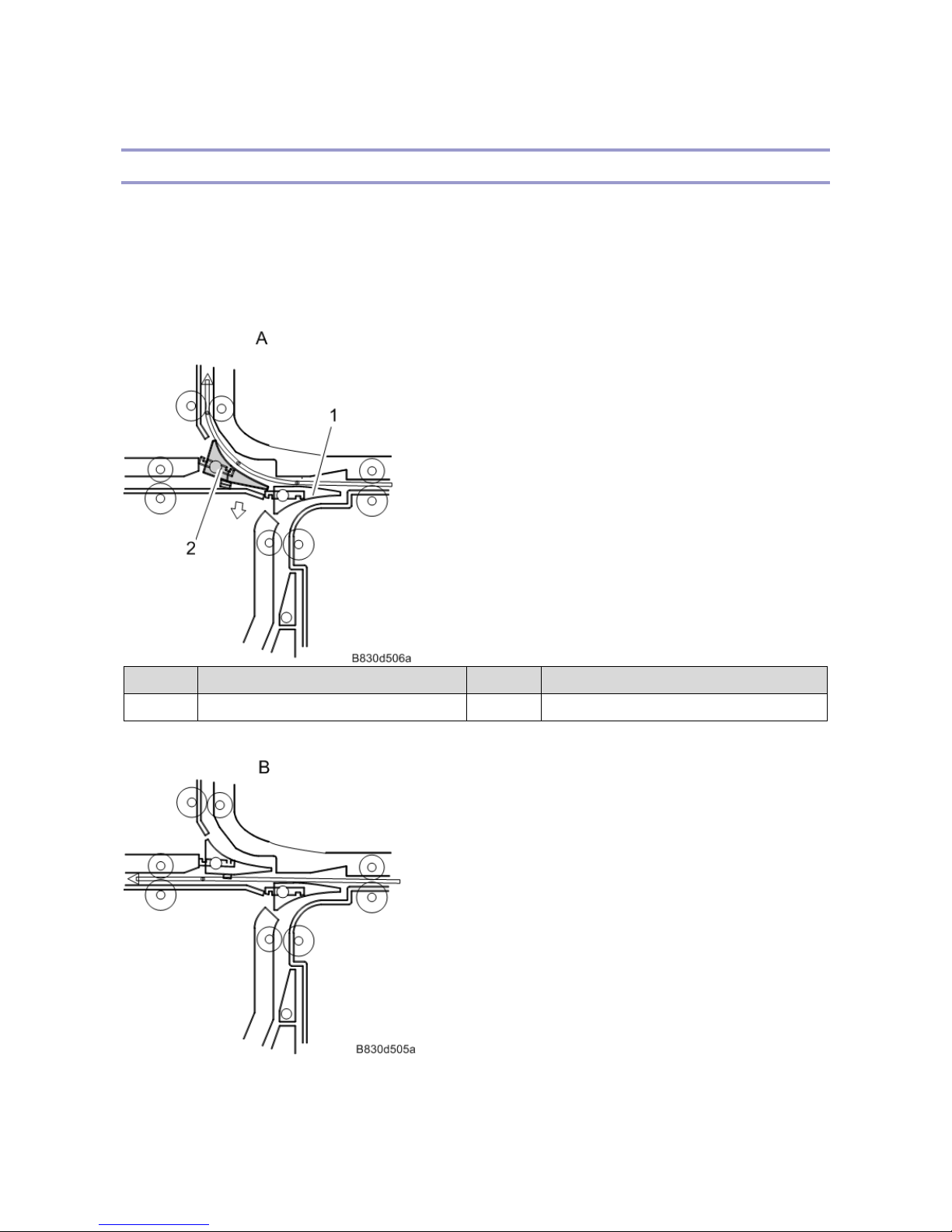
Inverter
The inverter mechanism has two junction gates that can send paper in one of three ways. For proof tray output, a
motor moves the proof junction gate into position to send paper to the proof tray. In staple mode, another motor
moves the stapler junction gate into position to send paper to the stapler. In shift mode, paper is sent to the shift
tray, and neither junction gate changes over.
Proof Mode
No. Description No. Description
1 Proof Junction Gate 2 Stapler Junction Gate
Shift Mode
Staple Mode
1.Detailed Descriptions
12
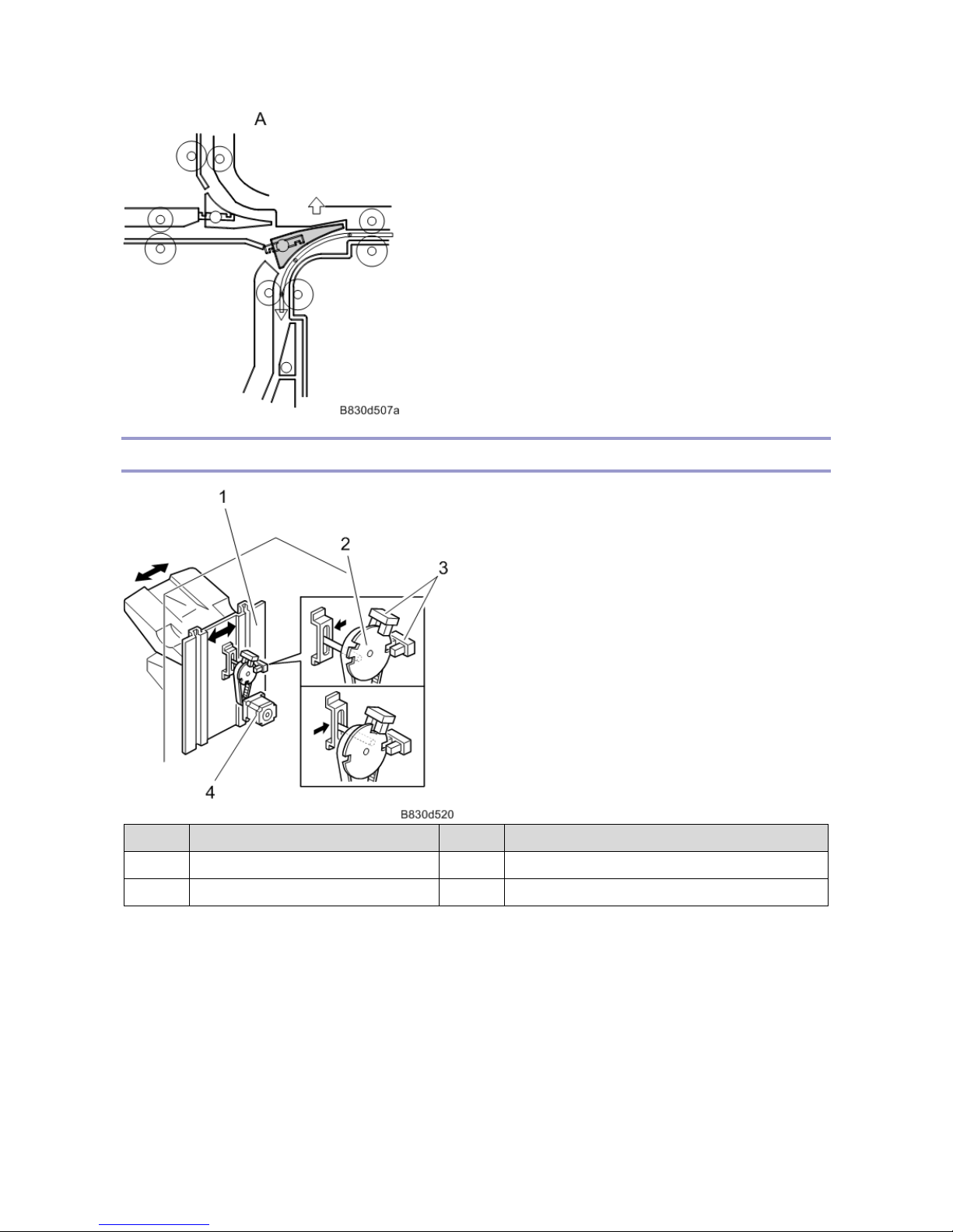
Shift Tray
No. Description No. Description
1 Shift Tray End Fence 3 HP Sensor
2 Shift Gear Disk 4 Shift Tray Half-turn Sensors
• Shift T ray
In shift mode, when the last printed paper has been output, the shift motor moves the shift tray to the left or
the right. When one of the half-turn sensors detects one of the slots in the shift gear disk, the motor stops.
The shift amount is 15mm..
• Up / Down
The shift tray moves up or down depending on the stack height of the output paper. The degree of motion is
adjusted to keep the paper height sensor actuator (3) between the two paper height sensors (1, 2).

1.Detailed Descriptions
13
No. Description No. Description
1 Paper Height Sensor – Standby Mode 4 Shift Tray Full Sensor (Large Paper)
2 Paper Height Sensor – Staple Mode 5 Shift Tray Full Sensor
3 Paper Height Sensor Actuator 6 Paper Height Sensor – Shift Mode
• Shift Up
When paper is removed from the shift tray, the feeler moves down and the paper height sensor (staple mode)
turns ON. Then the shift tray lifts until the sensor turns “OFF”.
• Shift Down (Shift Mode)
With stacked paper on the tray, the paper height sensor (standby mode) is turned “OFF”. Then the shift tray
lift motor turns “ON” to lift the tray until the sensor turns “ON”.
• Shift Down (Staple Mode)
When a stapled stack of paper has been output, the shift tray lift motor turns ON for a certain time to move
the tray down a set distance. Then the motor lifts the tray until the paper height sensor (staple mode) turns
from “ON” to “OFF”. The tray is now at the home position. This is done every time after a stapled stack of
paper is output. There are three shift tray full sensors, but only two of these (4, 5 in the above diagram) are
used for the machine display.
Rough Indication:
Larger Size (B4 or larger): 1,500 sheets
Smaller Size (less than B4): 3000 sheets
• Drag Roller Operation
The drag roller mechanism improves the accuracy of paper stacking on the tray by pushing the output paper
1.Detailed Descriptions
14
back against the end fence. The drag roller motor drives the roller.
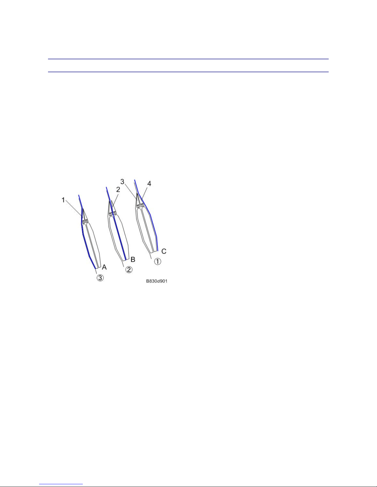
Pre-stack
The First Three Sheets
1. The rear edge of the 1st sheet passes the entrance sensor. Then the left and right pre-stack inverter plates shift
to the left. This closes the 2nd and 3rd paths to send paper to the 1st path.
2. The rear edge of the 2nd sheet passes the entrance sensor. Then the pre-stack inverter plate (right) shifts to
the right. This opens the 2nd path to send the 2nd sheet to the 2nd path.
3. The rear edge of the 3rd sheet passes the entrance sensor. Then, the pre-stack inverter plate (left) shifts to the
right. This opens the 3rd path to send 3rd sheet to the 3rd path. Then, after the leading edge of the 3rd sheet
passes the pre-stack sensor, the three sheets of paper (1st, 2nd, 3rd) are sent to the stapler tray at the same
time.
1. Junction Gate (JG) Left
2. JG Right
3. JG Left
4. JG Right
A: 3rd Transport Path
B: 2nd Transport Path
C: 1st Transport Path
Pre-stacking for Subsequent Sheets
When the rear edge of the 4th sheet passes the entrance sensor, the pre-stack inverter plate (left) shifts to the left to
open the 2nd path. This sends the 4th sheet to the 2nd path.
Then, after the leading edge of the 5th sheet passes the entrance sensor, the pre-stack inverter plate (left) shifts to
the right to open the 3rd path. This sends the 5th sheet to the 3rd path. When the leading edge of the 5th sheet
passes the pre-stack sensor, both sheets of paper are sent to the staple tray.
From now on until the end of the stack of paper to be stapled, paper is fed to the stapler two by two in this way.
 Loading...