

Page 1
Technical Bulletin No. RTB-014
SUBJECT: FINISHER ENTRANCE GUIDE DATE:Jan. 31, ’93
PAGE: 1 of 6
PREPARED BY: S. MANO
CHECKED BY:
CLASSIFICATION:
Action Required
Troubleshooting
Retrofit Information
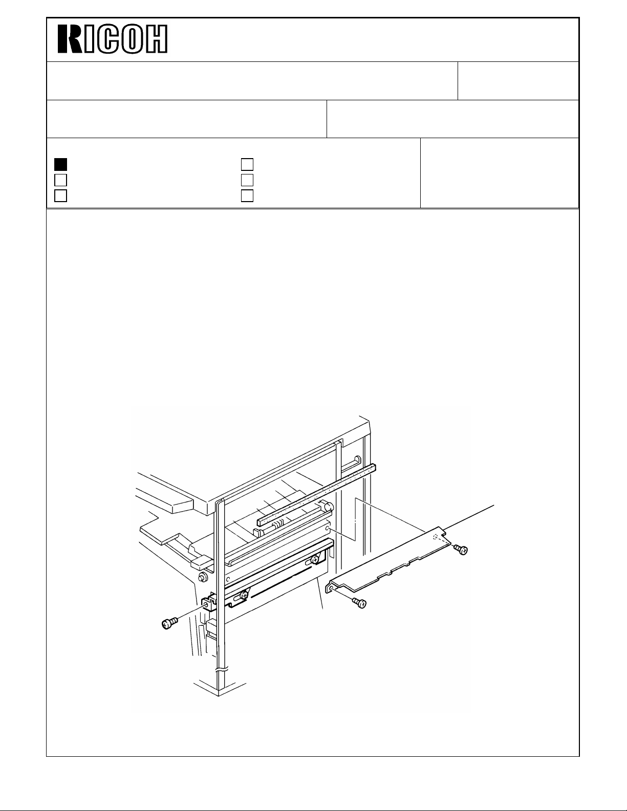
It has been reported that several sorter stapler (A377) entrance guide become deformed.
(This is introduced in F400/F410 RTB No.13, please refer to it for details)
Since the F400 finisher has the same type of guide plate, the entrance guide plate [A] is
separated from the finisher and kept in the accessory bag.
This is implemented from the first February 1994 production machine.
Whenever transporting the sorter stapler after taking out of the carton box, separate the
guide plate from the finisher. Reset it just before you dock the finisher to the copier.
The installation procedure (accessory) has also been modified. Please refer to the
following pages. Step #13 has been added. The other steps are the same as before.
Revision of service manual
Information only
Other
FROM: Copier Technical Support Section
MODEL:
F410 FINISHER
[A]
Page 2
Technical Bulletin No. RTB-014
[F]
[D]
SUBJECT: FINISHER ENTRANCE GUIDE DATE:Jan. 31, ’93
PAGE: 2 of 6
INSTALLATION PROCEDURE
[B]
[A]
[C]
[D]
[A]
[E]
[C]
[G]
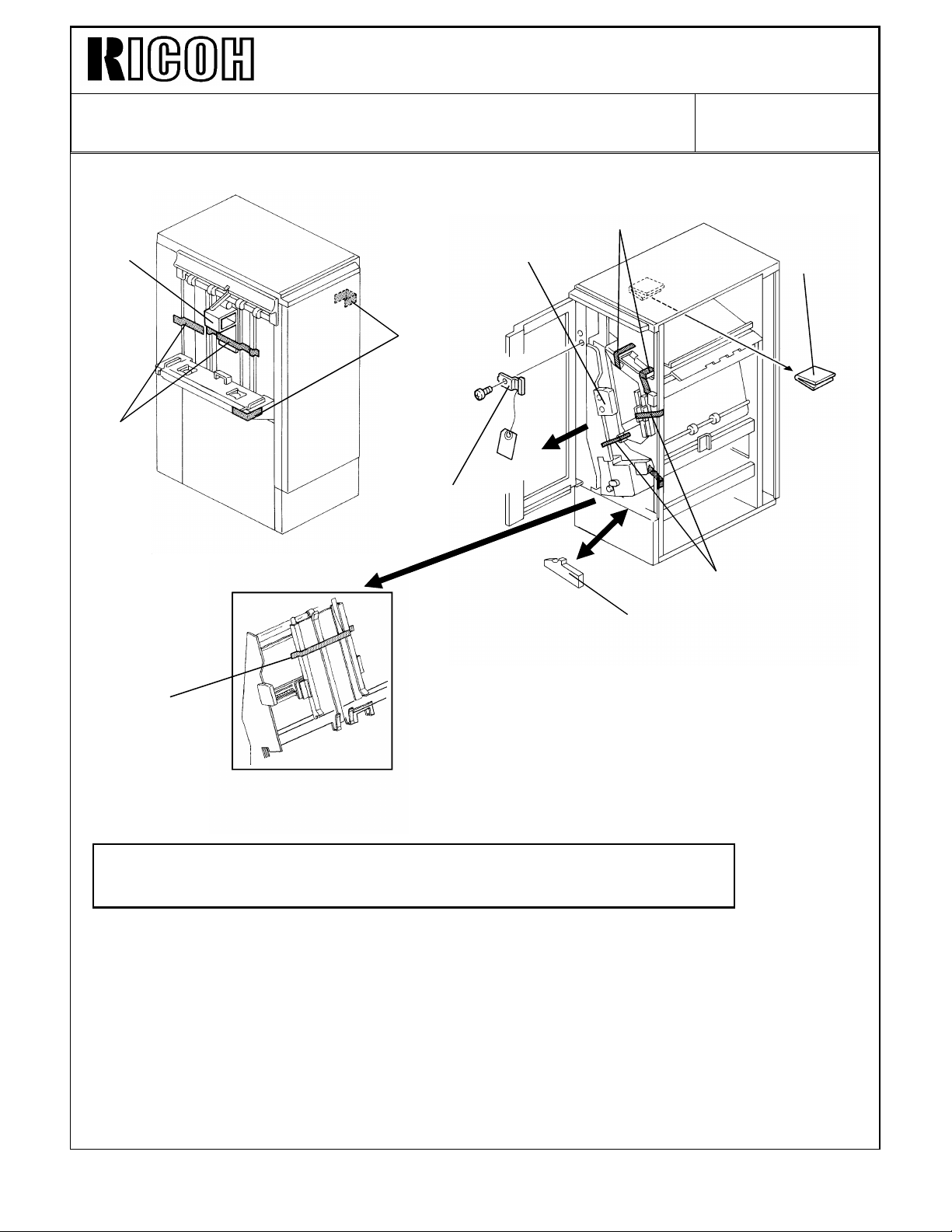
CAUTION: Unplug the copier power cord before starting the following
procedure.
1. Remove the strips of tape [A] and the cushion [B].
2. Open the front door and remove the strips of tape [C] and cushions [D].
3. Remove a clamp [E] (1 screw).
4. Slide out the staple unit [F].
5. Remove a strip of tape [G].
Page 3
Technical Bulletin No. RTB-014
SUBJECT: FINISHER ENTRANCE GUIDE DATE:Jan. 31, ’93
PAGE: 3 of 6
[C]
[B]
[A]
[D]
[E]
[D]
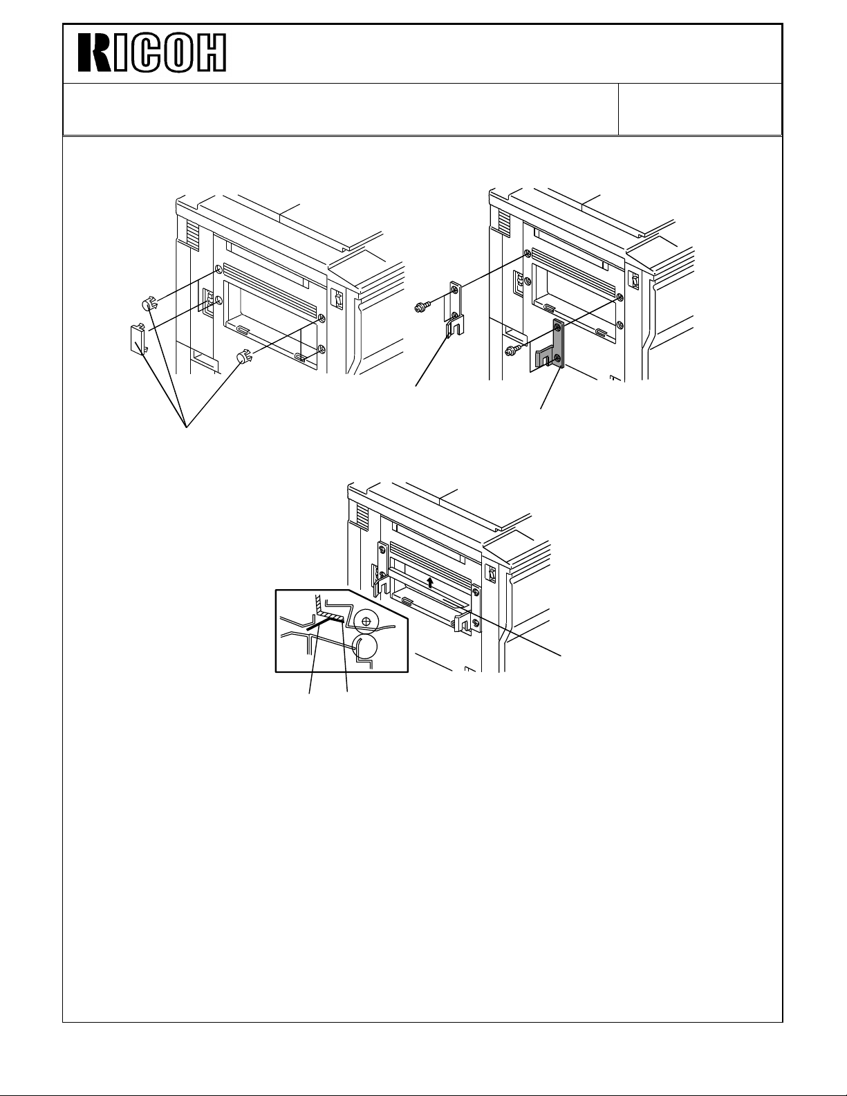
6. Remove five plastic caps [A] on the copier’s left cover.
7. Install the front connecting bracket [B] (2 screws– M4 x 12) and the rear connecting
bracket [C] (2 screws– M4 x 12) on the copier.
8. Stick the entrance guide mylar [D] on the copier exit area as shown.
NOTE: Align the edge [E] of the cover and the mylar.
Page 4
Technical Bulletin No. RTB-014
[F]
[K]
SUBJECT: FINISHER ENTRANCE GUIDE DATE:Jan. 31, ’93
PAGE: 4 of 6
[C]
[I]
[A]
[J]
[G]
[L]
[D]
[B]
[H]
[E]
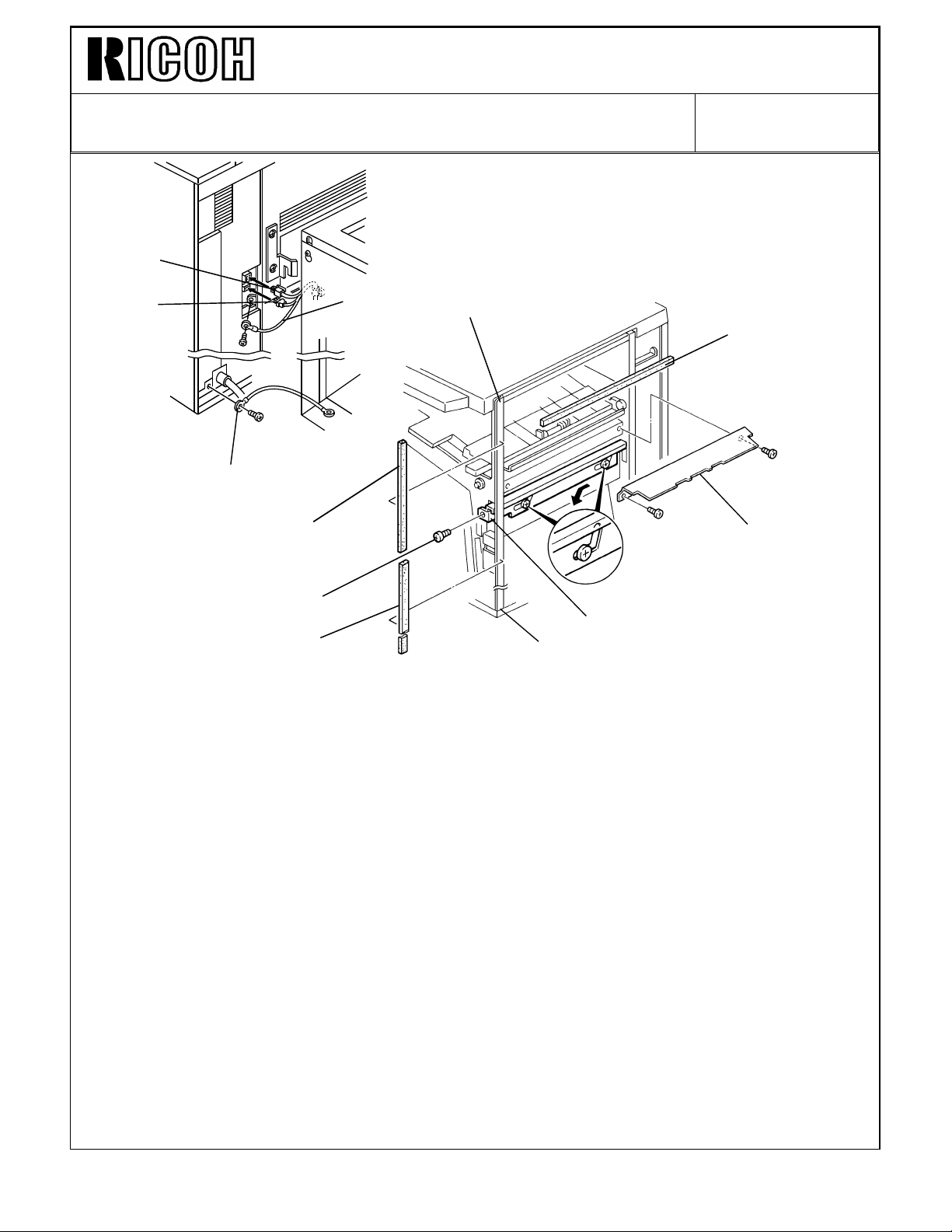
9. Secure the protective earth wire [A]* (1 screw with spring washer) and the wire [B] (1
screw with spring washer).
NOTE*: For all models other than those intended for North America, the green wire is
intended as a functional earth and should be connected as shown.
10. Connect the 4P connector [C] and the fiber optic connector [D].
11. Open the front door of the finisher and remove the screw [E] fixing the locking lever [F],
then lower the locking lever.
12. Stick the cushions [G] (middle) [H] (short) [I] (long) as shown.
NOTE: Stick the cushion [G] on the metal stay (not on the cover).
Align the upper edge of the cushion [H] with the edge of the stay [J].
Align the lower edge of the cushion [I] with the edge of the stay [K].
13. Install the entrance guide plate [L] (2 screws -M4 x 6).
Page 5

Technical Bulletin No. RTB-014
SUBJECT: FINISHER ENTRANCE GUIDE DATE:Jan. 31, ’93
PAGE: 5 of 6
[D]
[E]
[G]
[C]
[B]
[A]
[F]
14. Align and press the finisher against the copier and fix them by raising the locking lever
[A].
NOTE: At this time, confirm that the myler [B] locates between the guides [C].
15. Secure the locking lever [A] (1 screw).
16. Install the shift tray [D] with 4 screws – M4 x 8.
(Remove tape [E].)
17. Adjust the height of the copier by using the leveling feet [F] so that the difference in
level [G] between the copier and the finisher will be 30 ± 1 mm.
Page 6

Technical Bulletin No. RTB-014
SUBJECT: FINISHER ENTRANCE GUIDE DATE:Jan. 31, ’93
PAGE: 6 of 6
[B]
[A]
18. Remove the green plastic clip [A] from the staple cartridge, and install the cartridge in
the stapler.
NOTE: When installing the staple cartridge. Make sure that all the staple sheets [B]
are in the initial position.
19. Plug in the copier.
20. Turn on the main switch of the copier and test the operation of the finisher.
NOTE: The copier recognizes automatically that the finisher is installed.
The stapler will not staple for the first 10 or so copies until the first staple
comes to the proper position.
Page 7

Page 1 of Finisher
[A]
• Incorrect
Paper size Minimum: 5 1/2" x 8 1/2" / A5 sideways
Weight: 34.2 kg (75.4lb )
• Correct
Paper size Minimum: 5 1/2" x 8 1/2" / A6 lengthwise
Weight: 35 kg (77.2lb)
Page 8

Technical Bulletin No. RTB-017
SUBJECT: MANUAL CORRECTIONS DATE: Jan. 31,’94
PAGE: 13 of 13
Page 2 of Finisher Staple position (2 staple)
• Incorrect
b=5.20" ± 0.12" (13.2 ± 3 mm)
• Correct
b=5.20" ± 0.8" (132 ± 2 mm)
Page 25 of Finisher Step #6
• Incorrect
6. Remove the rear cover [G] (5 screws).
• Correct
6. Remove the rear cover [G] (6 screws).
Page 29 of Finisher Illustration
• Incorrect
Page 29 of Finisher Standard of item #1
[C]
[D]
• Correct
[C]
• Incorrect
Standard: 6mm deflection at 50 ± 20g pressure
• Correct
Standard: 6mm deflection at 180 ± 100g pressure
Page 9

Technical Bulletin No. RTB-027
SUBJECT: SC733 DATE:Mar. 15 ’94
PAGE: 1 of 3
PREPARED BY: S. MANO
CHECKED BY: S. Hamano
CLASSIFICATION:
Action Required
Troubleshooting
Retrofit Information
Revision of service manual
Information only
Other
FROM: 2nd Technical Support Section
MODEL: Finisher for F410
< POSSIBLE CAUSE - 1>
If the paper level actuator [A] is out of the position (See the illustration on page 2 of 3), the
machine may sense that the shift tray [B] has not arrived at the proper level even though
the shift tray [B] is at the maximum position (the stack height sensor 2 [C] is not actuated).
The fail safe mechanism (there is a safety switch [D] to detect the shift tray overrun
condition) stops the shift tray lift motor from trying to raise the shift tray any more.
[E]
[C]
[A]
[B]
[D]
Under this condition, the machine indicates the "R2" jam indication. If the front door of the
finisher is opened and closed and if the paper level actuator is still out of position, the
machine indicates SC733.
Page 10

Technical Bulletin No. RTB-027
SUBJECT: SC733 DATE: Mar. 15 ’94
PAGE: 2 of 3
The paper level actuator may be out of the position under the following situation:
1) The customer places something (for example, book, copies, etc.) [A] on the shift tray, it
pushes the actuator out of the position.
[A]
2) When the copy sets are delivered on the shift tray, the customer removes the copies. If
the operator reaches for the copies from just in front of the operation panel the operator
will not be able to see the actuator. It is possible for the operator to push the actuator
out of position when removing the copies.
< countermeasure>
1. Instruct the customer to return the actuator to the correct position (so that the actuator
becomes straight) and turn off then on the main switch.
2. The shift tray level actuator shape has been changed so that it cannot be bent easily.
This modification will be implemented from April 1994 production.
We will issue a Modification Bulletin as soon as the cut-in serial number becomes available.
Page 11

Technical Bulletin No. RTB-027
SUBJECT: SC733 DATE: Mar. 15 ’94
PAGE: 3 of 3
< POSSIBLE CAUSE - 2>
If there is obstacle (for example, desk, chair, dust box etc.) below the shift tray and it
prevents the shift tray from being lowered. The stack height sensor-1 [E] (See the
illustration in page 1 of 3) cannot be actuated. In this case, SC733 occurs.
< countermeasure>
Instruct the customer to remove the obstacle below the shift tray and then turn off then on
the main switch.
Page 12

Technical Bulletin No. RTB- 046
SUBJECT: SOFTWARE MODIFICATION DATE: Dec. 31, ’94
PAGE: 3 of 7
2. "B" version ROMs
From the following serial numbers, the EPROMs (A0965151A and A0965153A) on the
main board have been updated to version "B".
NOTE: We will re-issue this RTB as soon as the cut-in serial number becomes
available.
Code Serial Number
A095-10 5204
A095-15 264
A095-17 A3354
A095-22 5234
A095-26 3D5
A095-27 A3354
A095-29 A3354
A096-10 5244
A096-15 284
A096-17 A3364
A096-22 5274
A096-26 3D6
A096-27 A3364
A096-29 A3364
A097-10
A097-15
A097-17
A097-22
A097-26
A097-27
A097-29
Caution: Whenever replacing from the old main ROMs to the new version ROMs in
the field, this modification is necessary.
The following are corrected by this software change:
2-1. Machine enters the screen saver mode during auto counting
If the time to enter the screen saver mode (this time can be changed by using User tools)
comes during the auto count mode, the machine enters the screen saver mode. After
counting all originals, the machine indicates the original jam condition.
Page 13

Technical Bulletin No. RTB- 046
SUBJECT:SOFTWARE MODIFICATION DATE: Dec. 31, ’94
PAGE: 4 of 7
2-2. Operating time indication is incorrect
During operation, the time remaining before the end of the copy job is indicated by
animation on the touch panel screen.
During the duplex mode by using RDH and Finisher, the indicated time was incorrect.
<Countermeasure>
For the single side original to duplex copy mode, it is impossible to calculate the time due
to a highly complex operation using the alternate feed system. Therefore, in this mode,
the operating time is not indicated.
For the duplex original to duplex copy mode, the accuracy of the indicated operation time
has been improved.
2-3. RDH and Finisher, copy set limitation (maximum: 50 sets)
When using the RDH and Finisher, the selectable copy set for sort mode should be "999"
(In the sort mode, due to the alternate feed operation, the paper stocked in the duplex tray
is always less than 50 sheets). However, it was limited to 50. If a larger number was
entered, it was canceled and "50" was displayed.
2-4. RDH and Finisher, Copier misfeed caused by the original misfeed
When an original exit jam occurs in the RDH, it should not cause a copier misfeed (the
copier should exit all sheets in the copier then stop) but actually a misfeed also occurs in
the copier. This symptom occurs depending on the copy tray selected and the size of the
copy paper. (The combination of the longer paper path and shorter paper length tends to
create this symptom.)
 Loading...