

Page 1

FINISHER
(Machine Code:A379)
Page 2

23 April 1993 OVERALL MACHINE INFORMATION
1. OVERALL MACHINE INFORMATION
1.1 SPECIFICATIONS
Paper Size: Maximum: 11" x 17"/A3
Minimum: 51/2" x 81/2"/A5 sideways
Paper Weight: Standard copying/Stack mode
14 ~ 42 lb/52 ~ 157 g/m
Staple mode
17 ~ 20 lb/64 ~ 80 g/ m
Paper Capacity: 1,500 sheets:
81/2" x 11"/A4 or smaller size (20 lb/80 g/m2)
1,000 sheets:
81/2" x 14"/B4 or larger size (20 lb/80 g/m2)
Stapler Capacity: 81/2" x 11"/A4 or smaller size (20 lb/80 g/m2):
from 2 to 50 sheets
81/2" x 14"/B4 or large size (20 lb/80 g/m2):
from 2 to 30 sheets
2
2
Staple Replenishmen t: Cartridge exchange (5,00 0 pie ces/ cartridge)
Power Source: DC 24 V (from copier)
Power Consumption: 44.4 W (average)
Weight: 34.2 kg (75.4 lb)
Finisher
1
Page 3

b
(2 staples)
OVERALL MACHINE INFORMATION 23 April 1993
Stapling Position:
(1 staple)
a
b
b
aa
a = 0.24" ± 0.12" (6 ± 3 mm)
b = 0.24" ± 0.12" (6 ± 3 mm)
a = 0.24" ± 0.12" (6 ± 3 mm)
b = 0.24" ± 0.12" (6 ± 3 mm)
a = 0.24" ± 0.12" (6 ± 3 mm)
b = 5.20" ± 0.12" (13.2 ± 3 mm)
Dimensions: 26.4" x 20.2" x 37.4"
(671 mm x 514 mm x 950 mm)
Weight: 75.2 lb/34.2 kg
2
Page 4
12
23 April 1993 OVERALL MACHINE INFORMATION
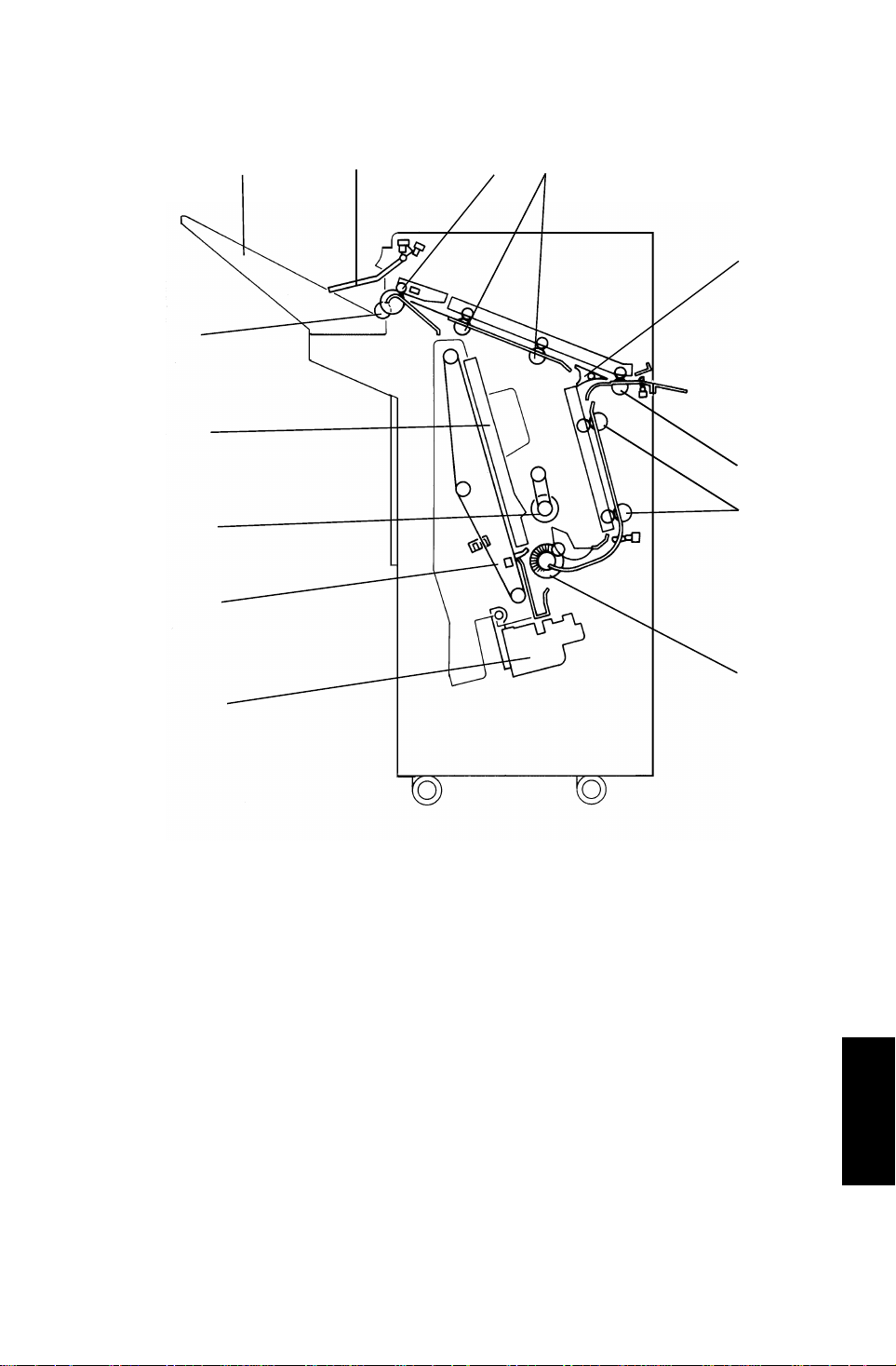
1.2 MECHANICAL COMPONENT LAYOUT
2
1
13
11
3
4
10
9
5
6
8
7
1. Stack Height Sensor Feeler
2. Shift Tray
3. Shift Tray Positioning Roller
4. Jogger Unit
5. Positioning Roller
6. Stack Feed-out Belt
7. Stapler Unit
8. Alignment Brush Roller
9. Lower Transport Rollers
10. Entrance Rollers
11. Junction Gate
12. Upper Transport Rollers
13. Exit Rollers
Finisher
3
Page 5

OVERALL MACHINE INFORMATION 23 April 1993
1.3 ELECTRICAL COMPONE NT DES CRI PTI O N
Refer to the electrical compone nt layou t on the reverse side of the Poin t to
Point (water proof paper) ind ex nu mbe rs.
Symbol Name Function
Motors
M1 Transport Drive Drives transport rollers. 23
M2 Shift Tray Lift Moves the shift tray up or down. 24
M3 Exit Drive Drives the exit and shif t tra y
positioning rollers.
M4 Stack Feed-out Drives the stack feed-out belt. 5
M5 Jogger Moves the jogger fen ces. 17
M6 Stapler Drive Moves the stapler unit . 14
M7 Shift Moves the shift tray side to side. 8
M8 Staple Drives the staple hammer. 12
Sensors
S1 Entrance Detects copy pap er entering into
the finisher.
S2 Jogger Unit Entrance Detects copy paper ente ring into
the jogger unit.
Index
No.
22
25
18
S3 Jogger Unit Paper Detects copy paper in the jogger
unit.
S4 Stack Feed-out BeltHPDetects the home positio n of the
stack feed-out belt.
S5 Jogger HP Detects the jogger home position. 16
S6 Exit Detects misfeeds in exit area. 3
S7 Stack Height 1 Detects copy pap er sta ck height
in staple mode.
S8 Stack Height 2 Detects copy pap er sta ck height
in sort/stack mode.
S9 Shift Tray Lower Limit Detects the lower limit of the shift
tray position.
S10 Stapler Hammer HP Detects the staple hammer home
position.
4
6
15
2
1
13
11
Page 6

23 April 1993 OVERALL MACHINE INFORMATION
Symbol Name Function
S11 Shift Tray Half-Turn Detects shift tray side-to-side
position.
S12 Stapler Unit HP Detects the stapler unit home
position.
S13 Staple End Detects staples in the cartrid ge 10
Switches
SW1 Front Door Safety
(Switch)
SW2 Shift Tray Upper
Limit (Switch)
Cuts dc power when the front
door is opened.
Detects the upper limit of the shift
tray position.
Solenoids
SOL1 Positioning Roller Lowers the positioning roller in
the jogger unit.
SOL2 Junction Gate Drives the junction gate. 21
Index
No.
7
9
26
4
19
PCBs
PCB1 Main Control Controls overall finisher o peration. 20
Finisher
5
Page 7
142
OVERALL MACHINE INFORMATION 23 April 1993
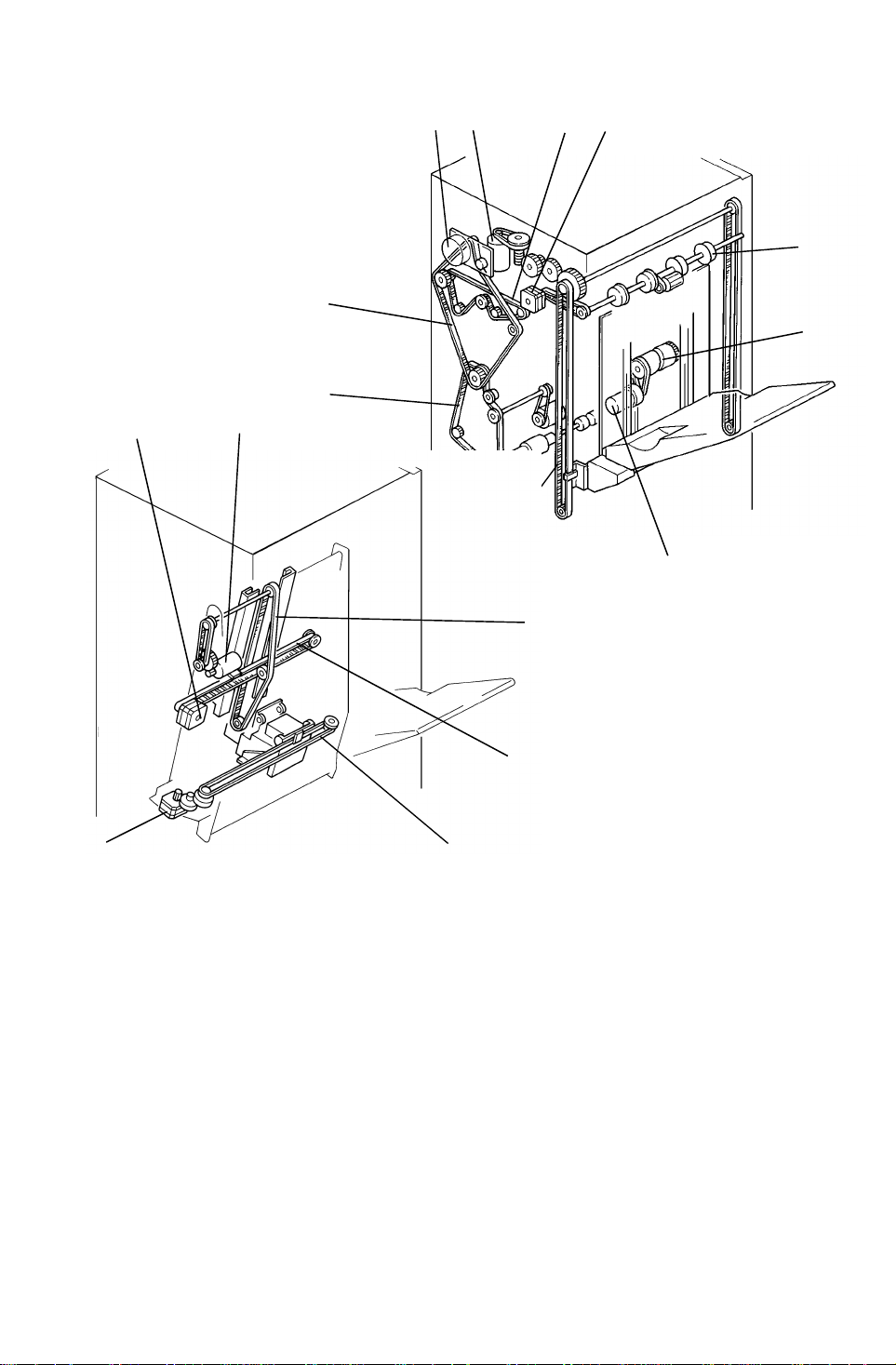
1.4 DRIVE LAYOUT
5
6
12
11
3
10
9
87
16
13
1. Exit Drive Motor
2. Upper Transport Drive Belt
3. Shift Tray Lift Motor
4. Transport Drive Motor
5. Transport Drive Belt
6. Lower Transport Drive Motor
7. Shift Tray Lift Belt
8. Shift Motor
15
14
9. Shift Cam
10. Exit Roller
11. Stack Feed-out Motor
12. Jogger Motor
13. Stapler Drive Motor
14. Stapler Drive Belt
15. Jogger Drive Belt
16. Stack Feed-out Belt
6
Page 8

23 April 1993 OVERALL MACHINE INFORMATION
1.5 BASIC OPERATI ON
[B]
[A]
[F]
[D]
[C]
[E]
After the copy is complet ed , the paper is directed to the finisher. If the
sort/stack mode is selecte d, the junction gate [A] directs the paper upwards
to transport it to the shif t tra y [B] . In the se mod es, the shift tray is shifted from
side to side to stagger a nd sepa rat e set s of copies. The amount of shift is
approximately 30 mm.
When the staple mode is selected, the junctio n gate direct s the paper below
to transport the paper to the jo gger un it [C] . Ea ch time a copy is delivered to
the jogger unit, the position ing ro ller [D] , th e alignment brush roller [E], and
the jogger fences [F] square the stack of copies. Af ter the final copy of the set
is squared, the set is stapled, and then delivered to th e shift tray.
7
Finisher
Page 9
SECTIONAL DESCRIPTIONS 23 April 1993
2. SECTIONAL DESCRIPTIONS
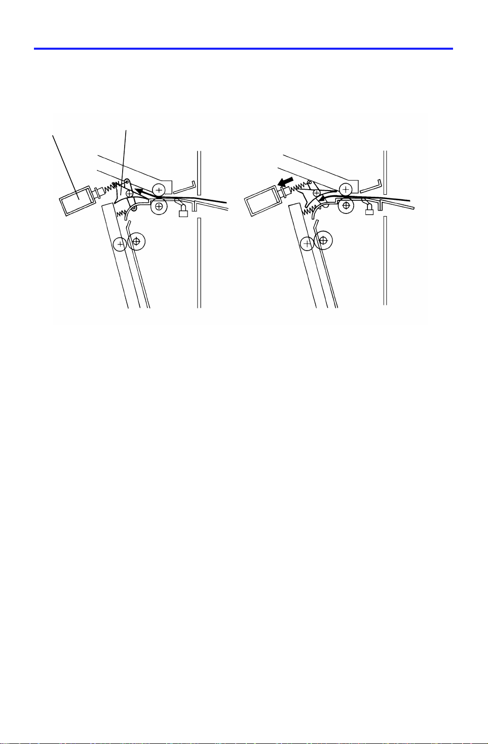
2.1 PAPER DELIVE RY S WI TCHI NG
[B]
[A]
Depending on the sele cte d finishing mode, the copie s are directed up or
down by the junction gate [A], is controlled by a solenoid.
(1) When the exit sensor of the copie r is activat ed while in staple mode, the
solenoid [B] is energ ized . Then, the junction gate dire cts the copies down
to transport them to the jogger unit.
(2) When the exit sensor of the copie r is activat ed while in the sort/stack
mode, the solenoid sta ys o ff . The ju nct ion gate directs the copies up to
deliver them to the shift tra y.
8
Page 10
[D]
[B]
23 April 1993 SECTIONAL DESCRIPTIONS
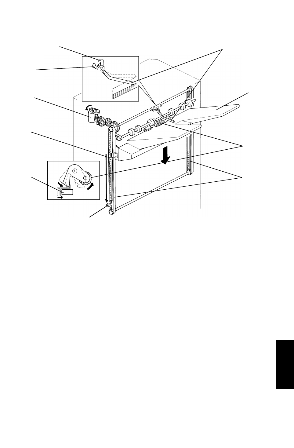
2.2 SHIFT TRAY UP/DOWN MECHANI S M
[H]
[I]
[E]
[F]
[A]
[J]
[C]
[G]
The vertical position of the shift tray [A] is controlle d by the shif t tra y lif t mot or
(dc motor) [B] through gears and timing belts [C]. Whe n the main switch is
turned on, the tray position is initialized to the upper posit ion . The tray’s
uppermost position is detected when the shift tray pushes up the actuator [D]
to deactuate the stack he ight sensor 1 [E].
While copying, the actua to r [ D] is grad ua lly raised as the copy stack grows. In
the sort/stack mode, when stack height sensor 2 [F ] rema ins actuated for 4
seconds, the shift tray lift moto r [B] rota te s, lowering the tray unit for 50 ms.
In staple mode, when the stack height sensor 1 re main s dea ctuated for 4
seconds, the motor rotate s, lowering the tray until the sensor [E] is actu at ed .
When the tray reaches its lower limit position, the lower limit sen sor [G] is
actuated by the actuator [H], and copy operation stops.
After the copy proce ss is finished and the machine stop s, th e tray is raised to
its upper most position 4 seconds after the copies are removed.
A mechanical safety switch [I] is inst alle d to preve nt the drive gears from
being damaged if the sensor doe s not work. Whe n th e shift tray pushes up
the shift tray positioning roller [J], the shift tray lift motor stops.
Finisher
9
Page 11

SECTIONAL DESCRIPTIONS 23 April 1993
2.3 SHIFT TRAY SIDE-TO -SIDE SHIFT MECHANISM
[B][C]
[A]
[E]
[D]
[F]
[G]
[H]
In the sort/stack mode, the shift tray [A] moves from side to side to stagger
and separate sets of copies.
The horizontal position of th e shif t tray is controlled by the shift motor (d c
motor) [B] and the shift cam (helical cam) [C]. After one set of originals is
copied and delivered to the shift tray, the shift moto r [B] start s rota tin g, driving
the shift cam through the timing belt. The pin [D] fixed to the shift tray base
plate [E] is position ed in the groo ve on the shift cam, creating the side-to -side
movement required to sta gger copies.
When the shift cam rotates 180 degrees (when the tray is fully shifted.), the
plate [F] on the shift cam pushes the actu at or [G] of the shift tray half-turn
sensor [H] and the shift motor sto ps. The next set of copies is then delivered.
The motor rotates rep ea tin g the same process and moving the tray ba ck to
the previous position.
10
Page 12

[F]
23 April 1993 SECTIONAL DESCRIPTIONS
2.4 STAPLE UNIT PAPE R PO SITI ONING
[C]
[B]
[F]
[E]
[A]
[H]
[G]
[C]
[D]
In the staple mode, copies are vertica lly a nd horizo nt ally alig ne d in the jog ge r
unit before being stapled.
For horizontal paper alignment, the jogger mot or [A ] moves both the front and
the rear jogger fences [B ] to align the copies.
For vertical paper alignment, the positio nin g rolle r [C] and the alig nme nt
brush roller [D] push the copy again st th e stack stopper [E].
After the trailing edge of the copy pa sses th e jogge r unit entrance sensor [F],
the positioning roller sole noid [G] is energized for 280 ms pushing th e
positioning roller into con ta ct with the paper. The po sitio nin g rolle r ro tate s to
push the paper back and align the trailin g edge of the pape r against the stack
stopper. Both the position ing roller and the alignment brush roller are driven
by the transport drive motor through the timin g belt [H] .
11
Finisher
Page 13

SECTIONAL DESCRIPTIONS 23 April 1993
2.5 JOGGER MOVEMENT
7 mm 2 mm
[A] [B]
(2)(1) (3)
When the Start key is pressed, the copier sends the paper size information to
the finisher. In accordance wit h th at data, the jogger motor (stepper mot or)
starts rotating to position the front and rear jogg er fe nces [A] 7 mm away from
the selected paper’s edges. (1)
After the trailing edge of the copy pa sses th e jogge r unit entrance sensor,
each jogger fence moves inwa rd 5 mm. The y st op 3 mm away from the paper
edges. (2)
Just after the positioning ro ller pushes the copy back, each jogger fence
moves inward 2 mm more so that the leaf spring [B] on the rear jogg er fe nce
pushes the copy side edge slightly.
After a copy is stacked in the jogg er tray, the jogger fences move back 7 m m
from the copy edge for the next copy.
12
Page 14

[C]
[G]
23 April 1993 SECTIONAL DESCRIPTIONS
2.6 STAPLER
[B]
[E]
[A]
[F]
[D]
The staple hammer [A] is driven by the staple motor [B] via gea rs [C], two
eccentric cams [D], and two links [E] .
When the aligned copies are brought to the staple position by the positioning
roller, alignment brush rolle r, an d jog ge r fen ces, the stapler motor starts
rotating. When the cams complete one rotation, the stapler home position
sensor [F] turns on detecting the end of the staple ope rat ion. The stapler
motor then stops.
There is a reflecting pho to sen sor [G] in the staple unit to detect the staple
end condition.
Finisher
13
Page 15

SECTIONAL DESCRIPTIONS 23 April 1993
2.7 STAPLER UNIT SIDE- TO-SIDE MOVEMENT
[A]
[B]
[C]
Customers can select one of the followin g th ree diff ere nt stap le mod es:
Staple 1: Top left
Staple 2: Bottom left
Staple 3: Top/Bottom left
The stapler drive motor [A ] (ste pp er mot or) move s the stap ler unit [B] from
side to side. When the Start key is pressed, the stapler moves from its home
position to the staple position.
If staple mode 3 is selected, the stap ler un it move s to th e fro nt stap le po sitio n
first, then moves to the rear stap le po sitio n. Howeve r, for the next copy set, it
staples in the reverse order; that is, at the rear side first and th en at th e front.
After the job is complet ed , the stapler unit moves back to its ho me position.
(The stapler unit home position sensor [C] is actuated.)
14
Page 16

23 April 1993 SECTIONAL DESCRIPTIONS
2.8 FEED-OUT TO SHI FT TRAY
[E]
[A]
[B]
[D]
[C]
[B]
After being stapled, the stack feed-out motor [A] starts rotating. The pawl [B]
on the lift belt [C] transports the set of st apled copies up, and feeds it to the
shift tray. Approximate ly 0.6 secon d after the stack feed-out mot or sta rts, the
motor stops for 400 ms. At this moment , th e exit ro llers cat ch th e sta ple d
copies to feed them out to th e shift tray. Then the motor rot ates again until
the pawl actuates its home position sensor [D].
The exit drive motor starts rotating to drive the exit rolle rs [E] when the first
copy activates the entrance sensor. The exit drive motor speed is reduced
just before each copy paper is comple tely fed out. This is to ensure an even
copy stack.
Finisher
15
Page 17

INSTALLATION 23 April 1993
3. INSTALLATION
3.1 ACCESSORY CHECK
Check the accessories in the box acco rdin g to the following list.
Description Q’ty
1. Installation Procedure.............................................................1
2. Front Connecting Bracket.......................................................1
3. Rear Connectin g Bracket .................... .. .......... .. .......... .. .........1
4. Staple Cartridge......................................................................1
5. Entrance Gu ide.............. .. .......... .. .......... .. .......... .. ...................1
6. Shift Tray ................................................................................1
7. NECR (for -17 machine only).................................................1
8. Cushion – 5 x 10 x 345............ .................... .. .......... .. .......... .. .1
9. Cushion – 5 x 10 x 125............ .................... .. .......... .. .......... .. .1
10. Cushion – 5 x 10 x 637............ .. .......... .. .................... .. .......... .1
11. Philips Truss Head Screw – M4 x 8 ............ .. .... .... .. .... .. .... .... .4
12. Philips Pan Head Screw – M4 x 12............... .. .. .... .. .. .. .. .. .. .... .4
13. Philips Screw with Flat Washer – M4 x 8...................... .... .. .. .2
14. Envelope – NECR (for -17 mach ine only)........... .. .............. .. .1
16
Page 18

[C]
[C]
23 April 1993 INSTALLATION
3.2 INSTALLATION PROCEDURE
[B]
[A]
[G]
[E]
[A]
[F]
[D]
[D]
CAUTION: Unplug the copier power cord before starti ng the follow ing
procedure.
1. Remove the strips of tap e [A ] an d th e cushion [B].
2. Open the front doo r and remove the strips of tape [C] and cushio ns [D].
3. Remove the clamp [E] (1 screw).
4. Slide out the staple unit [F] .
5. Remove the strip of tape [G].
17
Finisher
Page 19

INSTALLATION 23 April 1993
[C]
[B]
[A]
[D]
[D] [E]
6. Remove five plastic caps [A] on th e cop ier’s left cover.
7. Install the fro nt conn ecting bracket [B] (2 screws– M4 x 12) and the rear
connecting bracket [C] (2 screws– M4 x 12) on the copier.
8. Stick the entrance guide mylar [D] on the cop ier exit area as shown .
NOTE: Align the edge [E] of the cover and the mylar.
18
Page 20

[F]
23 April 1993 INSTALLATION
[J]
[G]
[C]
[D]
[M]
[A]
[B]
[H]
[E]
[I]
[M]
[K]
[L]
9. Secure the pro te ctive earth wire [A]* (1 screw with sprin g washer) and the
wire [B] (1 screw with spring washer).
*NOTE:For all models other than those intended for North America, the
green wire is meant to be used as a functional earth and should
be connected as shown.
10. Connect the fiber optics connector [C] and the 4P connector [D].
11. Open the front door of the finisher and remove the screw [E] fixing the
locking lever [F], then lower th e locking lever.
12. Stick the cushions [G] (mid dle ), [H] (short), [I] (long) as shown.
NOTE: Stick the cushion [G] on the metal stay (not on the co ver).
Align the upper edg e of the cu shio n [H] with the edge of the
stay [J].
Align the lower edge of the cushion [I] with the edge of the
stay [K].
13. Align and press the finisher against the copier and fix them by raising the
locking lever [F].
NOTE: At this time, confirm that the mylar [L] is located betwe en the
guides [M].
14. Secure the locking leve r (1 screw).
19
Finisher
Page 21

INSTALLATION 23 April 1993
[A]
[D]
[B]
[C]
15. Install the shift tra y [A] with 4 screws – M4 x 8 (re move tape [B ]).
16. Adjust the heigh t of the copier by using the leveling foot [C] so that the
difference in level betwe en the copie r [ D] and the finisher will be
30 ± 1 mm.
20
Page 22

23 April 1993 INSTALLATION
[B]
[A]
17. Remove the green plastic clip [A ] fro m t he st aple cartridge, and install the
cartridge in the stapler.
NOTE: When installing the staple cartridge, make su re th at all the staple
sheets [B] are in the init ial po sitio n.
18. Plug in the copier.
19. Turn on the main switch of the copier and test th e operation of the finisher.
NOTE: The copier recognizes automatically that the finisher is installed.
The stapler will not be stapling for the first 10 or so copies until
the first staple comes to th e pro pe r position from the cartridge.
21
Finisher
Page 23

SERVICE TABLES 23 April 1993
4. SERVICE TABLES
4.1 TEST POINT TABLE (Main Board)
Number Function
TP3 GND
4.2 FUSE TABLE
Number Rated Current Location
Fuse 1 5A Main PCB
4.3 LED TABLE
LED No. ON Status
LED1 Motor speed is too high.*
LED3 Motor speed is too low.*
*NOTE:While each motor is adjusted, if the motor speed is normal, LED
1 and LED 3 light. If the motor speed is too high, only LED 1
lights. If the motor spe ed is too low, only LED 3 lights.
There is no LED 2.
4.4 DIP SW TABLE
4.4.1 Factory Setting
DIP SW101 DIP SW102
12341234
00000000
4.4.2 Motor Test Mode
DIP SW101 DIP SW102
12341234
11011000Stack Feed-out Motor
After setting DIP SW101, turn on switch 1 of DIP SW102 to start
the stack feed-out mot or, turn off the DIP SW102 to sto p the motor.
Motor
22
Page 24

23 April 1993 SERVICE TABLES
4.4.3 Free Run Test Mode Without Paper
DIP SW101 DIP SW102
Function
12341234
11101000Shift Tray Mode
11100100Staple mode - (1)
11100010Staple mode - (2)
11100001Staple mode - (3)
Free run test mode starts when SW101 on the main board is
pressed, and stop when the push SW102 is pressed.
If in shift tray mode, the fin ishe r wo rks as if 10 set s of 5 LT pape rs
are being sorted. The shift tray is lowered for each of the 2 sets an d th en
returns to its home posit ion to repeat the same operat ion.
If in staple mode, the fin ishe r works a s if 5 sets of 5 LT papers are bein g
stapled and delivered . The ma chin e is t hen initialized and repeats the
same operation.
4.4.4 Off Line Test Mode
DIP SW101
Mode
DIP SW102
1 2 3 4 1 2 Copy Q’ty 3 4 Paper Size
1 1 0 0 Shift Tray Mode 0 0 2 sheets 0 0
1001
0110
0101
Staple Mode
(1)
Staple Mode
(2)
Staple Mode
(3)
1 0 10 sheets 1 0
0 1 30 sheets 0 1
1 1 50 sheets 1 1
A4
Sideways
A4 Length -
wise
LT
Sideways
LT Length-
wise
Off line test mode starts when SW101 on the main board is presse d, and
stops when SW102 is pressed.
The operation of the finisher can be checked without the main copier.
Finisher
23
Page 25

SERVICE TABLES 23 April 1993
4.4.5 Shift Tray Rise Mode
DIP101 DIP102
12341234
10000000
0: OFF 1: ON
In this mode, the shift tray moves to its uppermost positio n if the copy paper
stacked on the tray is removed while st aple mode copying.
When the stapling copy mode is used with the shif t tray rise mode, the shift
tray moves up and down slightly fo r each stapled copy set delivered to th e
tray.
[A]
OFF
ON
NOTE: In the stapling copy mode (unlike the sort copy mod e), the machine
cannot detect if the copy st ack on the tray is remove d. This is
because the stack heig ht sensor 1 [A] is always ON while in this
copy mode. To counter th is, whe n the shift tray rise mode is selecte d
by turning on DIP switch 101-1 on the finisher main control board ,
the shift tray slightly mo ves up just when the stapled copy is
delivered. At this time, if the stack he igh t sensor 1 turns off, this
means that the tray is in the proper po sitio n. The tra y mo ves down
soon and returns to the original position (unt il the sensor turns on
again). If the sensor remain s ON, th is mean s tha t th e tra y position is
too low. The tray continu ously mo ves up unt il the senso r turns off
then moves down until the sen sor tu rns on . In this mode the shift tray
motor frequently raises or lowers the shift tra y to monitor the paper
height.
To reduce the load to the shift tray motor, this mode is not enabled
as the factory setting.
24
Page 26

[E]
23 April 1993 REPLACEMENTS AND ADJUSTMENTS
5. REPLACEMENTS AND ADJUSTMENTS
5.1 EXTERIOR REMOVAL
[H]
[I]
[G]
[A]
[B]
[C]
[D]
[J]
1. Remove the left upper cover [A] (2 screws).
2. Remove the upper cover [B] (3 screws).
3. Remove the upper door bracket [C] (1 screw) and remove the front door
[D].
4. Remove the lower front cover [E ] (2 screws).
5. Remove the front shif t cove r [ F] (2 screws).
6. Remove the rear cover [G] (5 screws).
7. Remove the shift tray [H] (4 screws).
8. Remove the front an d rear tray cover [I] (1 screws at th e fro nt, 2 screws
at the rear).
9. Remove the left cover [J] (4 screws).
[I]
[F]
Finisher
25
Page 27

REPLACEMENTS AND ADJUSTMENTS 23 April 1993
5.2 ALIGNMENT BRUSH ROLLER REPLACE MENT
[A]
[H]
[B]
[D]
[I]
[J]
[I]
[H]
[C]
[E]
[F]
[G]
[F]
1. Remove the rear cover.
2. Remove the main board [A] (15 connectors, 1 optics cable).
3. Remove the tension bracke t [B ] (1 screw an d 1 sprin g).
4. Remove the E-rings [C], slide ou t th e pu lleys [D] , an d remo ve 2 E-rings
[E] , then remove 2 bushings [F].
[E]
5. Remove the alignmen t bru sh rolle r a ssemb ly [G] .
6. Remove the 2 E-ring [H] and remo ve th e brush rollers [I].
NOTE: Do not lose the link keys [J].
26
Page 28

23 April 1993 REPLACEMENTS AND ADJUSTMENTS
5.3 SENSOR REPLACEME NT
[E]
[C]
[D][A]
Stack Height Sensors
1. Remove the upper cover.
2. Remove the stack height sensor actuator [A] (1 screw).
3. Remove the bracket [B ] (1 screw, 2 connectors).
4. Replace stack height sensor 1 [C] and stack height sensor 2 [D].
NOTE: When reinstalling the bracket [B], align the edge of the bracket
with the stay [E].
[B]
Finisher
27
Page 29

REPLACEMENTS AND ADJUSTMENTS 23 April 1993
5.4 POSITING ROLLER REP LACEME NT
[A]
1. Open the front door and slid e out the jogger unit.
2. Remove the position ing roller [A ] (1 clip).
28
Page 30

[D]
23 April 1993 REPLACEMENTS AND ADJUSTMENTS
5.5 BELT TENSION ADJUSTMENT
[B]
[C]
[A]
[A, B]
[a, b]
[C]
[c]
1. Remove the rear cover and ad just the belt
[A] tension with tigh tener [a].
Remove the left upper cover, the upper
cover, the front door, and the front shift cover
and the front supporting cover (2 screws).
Adjust the belt [B] with tightener [b].
Standard: 6 mm deflection at 50 ± 20 g
pressure.
2. Open the front door an d slide out the jogg er
unit. Adjust the belt [C] ten sion with
tightener [c].
Finisher
Standard: 8 mm deflection at 100 ± 30 g
pressure.
29
Page 31

REPLACEMENTS AND ADJUSTMENTS 23 April 1993
[D]
[d]
150 ± 40 g
3. Open the front doo r and slid e ou t th e jogger unit. Adjust the belt [D ]
tension with tight en er [d ].
Standard: 8 mm deflection at 150 ± 40 g pressure.
30
 Loading...