

Page 1

Model PR-C1
Machine Code: (D010)
SERVICE MANUAL
Feb. 19th, 2007
Subject to change
Page 2

Safety Notices
Important Safety Notices
Prevention of Physical Injury
1. Before disassembling or assembling parts of the copier and peripherals, make sure that the copier
power cord is unplugged.
2. The wall outlet should be near the copier and easily accessible.
3. If any adjustment or operation check has to be made with exterior covers off or open while the main
switch is turned on, keep hands away from electrified or mechanically driven components.
4. The copier drives some of its components when it completes the warm-up period. Be careful to keep
hands away from the mechanical and electrical components as the copier starts operation.
5. The inside and the metal parts of the fusing unit become extremely hot while the copier is operating.
Be careful to avoid touching those components with your bare hands.
Health Safety Conditions
1. Toner and developer are non-toxic, but if you get either of them in your eyes by accident, it may cause
temporary eye discomfort. Immediately wash eyes with plenty of water. If unsuccessful, get medical
attention.
2. This machine, which uses a high voltage power source, can generate ozone gas. High ozone density
is harmful to human health. Therefore, the machine must be installed in a well-ventilated room.
Observance of Electrical Safety Standards
This machine and its peripherals must be serviced by a customer service representative who has completed
the training course on those models.
• Keep the machine away from flammable liquids, gases, and aerosols. A fire or an explosion might
occur.
Safety and Ecological Notes for Disposal
1. Do not incinerate toner bottles or used toner. Toner dust may ignite suddenly when exposed to an
open flame.
1
Page 3

2. Dispose of used toner, the maintenance unit which includes developer or the organic photoconductor
in accordance with local regulations. (These are non-toxic supplies.)
3. Dispose of replaced parts in accordance with local regulations.
Laser Safety
The Center for Devices and Radiological Health (CDRH) prohibits the repair of laser-based optical units
in the field. The optical housing unit can only be repaired in a factory or at a location with the requisite
equipment. The laser subsystem is replaceable in the field by a qualified Customer Engineer. The laser
chassis is not repairable in the field. Customer engineers are therefore directed to return all chassis and
laser subsystems to the factory or service depot when replacement of the optical subsystem is required.
• Use of controls, or adjustment, or performance of procedures other than those specified in this manual
may result in hazardous radiation exposure.
• WARNING: Turn off the main switch before attempting any of the procedures in the Laser Optics
Housing Unit section. Laser beams can seriously damage your eyes.
• CAUTION MARKING:
2
Page 4
Symbols and Abbreviations
This manual uses several symbols and abbreviations. The meaning of those symbols and abbreviations are
as follows:
* See or Refer to
Clip ring
Screw
Connector
Clamp
E-ring
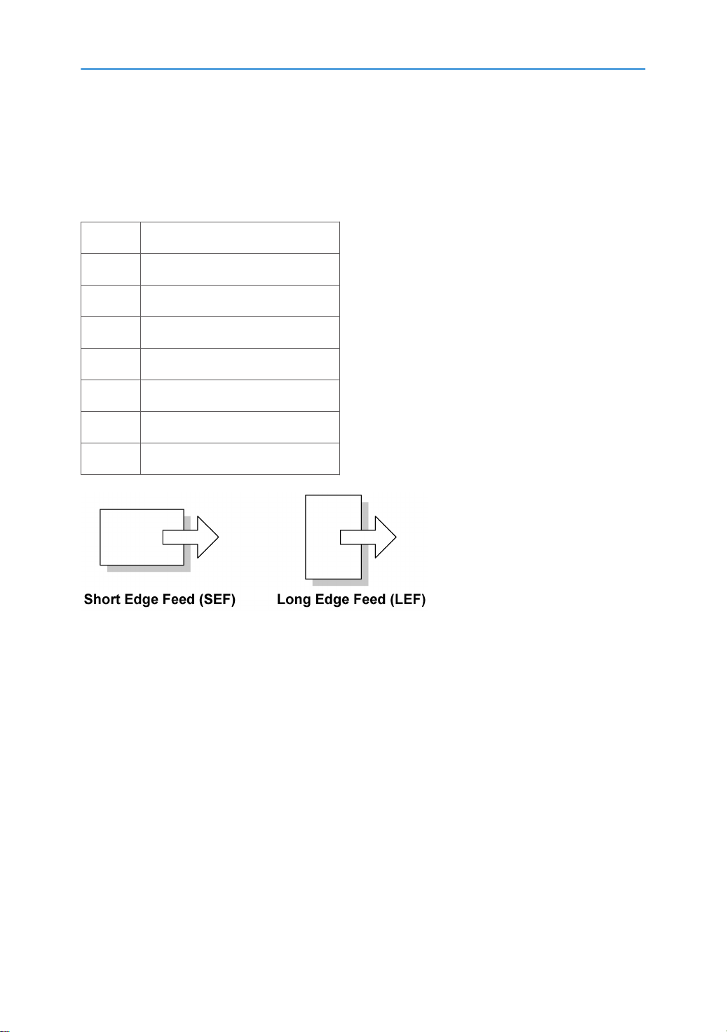
SEF Short Edge Feed
LEF Long Edge Feed
3
Page 5

TABLE OF CONTENTS
Safety Notices.....................................................................................................................................................1
Important Safety Notices...............................................................................................................................1
Safety and Ecological Notes for Disposal...................................................................................................1
Laser Safety.....................................................................................................................................................2
Symbols and Abbreviations...............................................................................................................................3
1. Installation
Installation Requirements.................................................................................................................................13
Environment..................................................................................................................................................13
Machine Level..............................................................................................................................................14
Minimum Space Requirements...................................................................................................................14
Power Requirements....................................................................................................................................15
Copier Installation............................................................................................................................................16
Power Sockets for Peripherals....................................................................................................................16
Accessory Check..........................................................................................................................................16
Installation Procedure..................................................................................................................................17
Platen Cover Installation..................................................................................................................................22
Accessory Check..........................................................................................................................................22
Installation Procedure..................................................................................................................................22
ARDF Installation..............................................................................................................................................23
Accessory Check..........................................................................................................................................23
Installation Procedure..................................................................................................................................24
Two-tray Paper Tray Unit Installation.............................................................................................................27
Accessory Check..........................................................................................................................................27
Installation Procedure..................................................................................................................................27
One-Bin Tray Installation.................................................................................................................................29
Accessory Check..........................................................................................................................................29
Installation Procedure..................................................................................................................................29
Bridge Unit Installation.....................................................................................................................................32
Component Check.......................................................................................................................................32
Installation Procedure..................................................................................................................................32
500-Sheet Finisher (B792)..............................................................................................................................37
Accessory Check..........................................................................................................................................37
Installation Procedure..................................................................................................................................38
4
Page 6

Anti-condensation Heater Installation............................................................................................................41
Tray Heaters.....................................................................................................................................................42
Tray Heater...................................................................................................................................................42
Tray Heaters for the Optional Paper Feed Unit.........................................................................................43
Key Counter Interface Installation...................................................................................................................47
GDI Expansion.................................................................................................................................................49
Accessory Check..........................................................................................................................................49
Installing Expansion Component................................................................................................................49
PCL Option........................................................................................................................................................52
Accessory Check..........................................................................................................................................52
Installing PCL Option...................................................................................................................................52
Mechanical Counter........................................................................................................................................56
Component Check.......................................................................................................................................56
Installing Mechanical Counter....................................................................................................................56
2. Preventive Maintenance
PM Tables.........................................................................................................................................................61
Optics............................................................................................................................................................61
Drum Area....................................................................................................................................................61
Paper Feed...................................................................................................................................................62
Fusing Unit....................................................................................................................................................63
ARDF.............................................................................................................................................................63
Paper Tray Unit............................................................................................................................................63
How to Reset the PM Counter.........................................................................................................................65
3. Replacement and Adjustment
General Cautions.............................................................................................................................................67
PCU (Photoconductor Unit).........................................................................................................................67
Transfer Roller..............................................................................................................................................67
Scanner Unit.................................................................................................................................................67
Laser Unit......................................................................................................................................................68
Fusing Unit....................................................................................................................................................68
Paper Feed...................................................................................................................................................68
Special Tools and Lubricants...........................................................................................................................70
Exterior Covers and Operation Panel............................................................................................................71
5
Page 7

Rear Cover...................................................................................................................................................71
Tray Harness Cover.....................................................................................................................................71
Copy Tray.....................................................................................................................................................72
Inner Cover...................................................................................................................................................72
Upper Covers...............................................................................................................................................73
Left Cover......................................................................................................................................................74
Front Cover...................................................................................................................................................74
Front Right Cover.........................................................................................................................................75
Right Rear Cover..........................................................................................................................................75
Right Door (Duplex Unit).............................................................................................................................76
By-pass Tray.................................................................................................................................................77
Right Lower Cover........................................................................................................................................78
Platen Cover Sensor....................................................................................................................................78
Scanner Unit.....................................................................................................................................................79
Exposure Glass/DF Exposure Glass .........................................................................................................79
Lens Block.....................................................................................................................................................80
Lamp Stabilizer Board and Exposure Lamp..............................................................................................81
Original Width/Length Sensor...................................................................................................................82
Scanner Motor.............................................................................................................................................84
Scanner Home Position Sensor...................................................................................................................85
Adjusting Scanner Positions........................................................................................................................86
Laser Unit..........................................................................................................................................................90
Location of Caution Decal...........................................................................................................................90
Toner Shield Glass.......................................................................................................................................91
Laser Unit......................................................................................................................................................91
LD Unit...........................................................................................................................................................92
Polygonal Mirror Motor..............................................................................................................................93
Laser Unit Alignment Adjustment................................................................................................................93
PCU Section......................................................................................................................................................96
PCU...............................................................................................................................................................96
Pick-off Pawls and Toner Density Sensor...................................................................................................97
OPC Drum....................................................................................................................................................98
Charge Roller and Cleaning Brush.............................................................................................................99
6
Page 8

Cleaning Blade..........................................................................................................................................100
Developer..................................................................................................................................................101
After Replacement or Adjustment.............................................................................................................102
Toner Supply Motor......................................................................................................................................103
Paper Feed Section........................................................................................................................................104
Paper Feed Roller: Tray 1 ........................................................................................................................104
Paper Feed Roller: Tray 2.........................................................................................................................104
Friction Pad................................................................................................................................................105
Paper End Sensor......................................................................................................................................105
Upper/Lower Paper Lift Motors...............................................................................................................106
Exit Sensor..................................................................................................................................................107
By-Pass Feed Roller and Paper End Sensor............................................................................................108
Registration Roller......................................................................................................................................109
By-Pass Paper Size Switch........................................................................................................................110
Registration Clutch ....................................................................................................................................111
Registration Sensor....................................................................................................................................111
Upper Paper Feed Clutch and By-Pass Feed Clutch..............................................................................112
Relay Clutches...........................................................................................................................................113
Upper Relay Sensor..................................................................................................................................113
Lower Relay Sensor ..................................................................................................................................114
Lower Paper Feed Clutch..........................................................................................................................114
Upper/Lower Paper Size Sensors...........................................................................................................115
Upper/Lower Paper Lift Sensor...............................................................................................................116
Upper/Lower Paper Height Sensors.......................................................................................................117
Image Transfer...............................................................................................................................................119
Image Transfer Roller................................................................................................................................119
Image Density Sensor...............................................................................................................................120
Discharge Plate..........................................................................................................................................121
Fusing..............................................................................................................................................................124
Fusing Unit..................................................................................................................................................124
Thermistor...................................................................................................................................................125
Fusing Lamps..............................................................................................................................................125
Hot Roller Stripper Pawls..........................................................................................................................126
7
Page 9

Hot Roller...................................................................................................................................................127
Thermostat..................................................................................................................................................127
Pressure Roller and Bushings....................................................................................................................128
Nip Band Width Adjustment.....................................................................................................................128
Cleaning Roller..........................................................................................................................................130
Duplex Unit ....................................................................................................................................................131
Duplex Exit Sensor....................................................................................................................................131
Duplex Entrance Sensor............................................................................................................................131
Duplex Inverter Sensor..............................................................................................................................132
Duplex Transport Motor...........................................................................................................................133
Duplex Inverter Motor...............................................................................................................................133
Other Replacements......................................................................................................................................135
Quenching Lamp.......................................................................................................................................135
High-Voltage Power Supply Board.........................................................................................................135
BICU (Base-Engine Image Control Unit).................................................................................................136
Main Motor...............................................................................................................................................137
Duplex Fan.................................................................................................................................................137
Rear Exhaust Fan.......................................................................................................................................138
PSU (Power Supply Unit)..........................................................................................................................139
Gearbox.....................................................................................................................................................140
Copy Adjustments Printing/Scanning..........................................................................................................142
Printing........................................................................................................................................................142
Scanning....................................................................................................................................................144
ARDF Image Adjustment...........................................................................................................................146
4. Troubleshooting
Service Call Conditions.................................................................................................................................149
Summary....................................................................................................................................................149
SC Code Descriptions...............................................................................................................................149
Electrical Component Defects.......................................................................................................................164
Sensors.......................................................................................................................................................164
Switches.....................................................................................................................................................167
Blown Fuse Conditions..................................................................................................................................168
LED Display....................................................................................................................................................169
8
Page 10

BICU...........................................................................................................................................................169
5. Service Tables
Service Program Mode.................................................................................................................................171
How to Enter the SP Mode.......................................................................................................................171
Copier SP Mode Tables................................................................................................................................173
SP1-XXX (Feed).........................................................................................................................................173
SP2-XXX (Drum).........................................................................................................................................177
SP3-XXX (Process).....................................................................................................................................181
SP4-XXX (Scanner)....................................................................................................................................185
SP5-XXX (Mode).......................................................................................................................................194
SP6-XXX (Peripherals)...............................................................................................................................197
SP7-XXX (Data Log)..................................................................................................................................199
SP8-XXX (Data Log 2)...............................................................................................................................205
SP9-XXX (Etc.)............................................................................................................................................210
Printer/Scanner SP Mode Tables (GDI Controller only)...........................................................................211
Printer Service Mode.................................................................................................................................211
Scanner System and Others.....................................................................................................................211
Using SP Modes.............................................................................................................................................212
Adjusting Registration and Magnification...............................................................................................212
ID Sensor Error Analysis (SP 3310).........................................................................................................212
Display APS Data (SP 4301-1)...............................................................................................................213
Memory Clear...........................................................................................................................................214
Input Check ...............................................................................................................................................216
Output Check ............................................................................................................................................221
Serial Number Input (SP 5811)...............................................................................................................224
NVRAM Data Upload/Download (SP 5824/5825)...........................................................................225
Firmware Update Procedure ...................................................................................................................227
Test Pattern Print (SP 5902-1)..................................................................................................................231
Paper Jam Counters (SP 7504)...............................................................................................................234
SMC Print (SP 5990)................................................................................................................................235
Original Jam History Display (SP 7508).................................................................................................235
ADF APS Sensor Output Display (SP 6901)...........................................................................................236
6. Detailed Section Descriptions
9
Page 11

Overview........................................................................................................................................................239
Component Layout....................................................................................................................................239
Paper Path..................................................................................................................................................241
Drive Layout...............................................................................................................................................242
Board Structure..............................................................................................................................................243
Block Diagram...........................................................................................................................................243
BICU (Base Engine and Image Control Unit)..........................................................................................244
SBU (Sensor Board Unit)..........................................................................................................................244
Copy Process Overview................................................................................................................................245
Scanning.........................................................................................................................................................247
Overview....................................................................................................................................................247
Scanner Drive............................................................................................................................................248
Original Size Detection in Platen Mode..................................................................................................249
Image Processing...........................................................................................................................................252
Overview....................................................................................................................................................252
SBU (Sensor Board Unit)..........................................................................................................................253
IPU (Image Processing Unit).....................................................................................................................254
Video Control Unit (VCU).........................................................................................................................264
Laser Exposure...............................................................................................................................................266
Overview....................................................................................................................................................266
Auto Power Control (APC)........................................................................................................................267
LD Safety Switch........................................................................................................................................268
Photoconductor Unit (PCU)...........................................................................................................................269
Overview....................................................................................................................................................269
Drive...........................................................................................................................................................270
Drum Charge.................................................................................................................................................271
Overview....................................................................................................................................................271
Charge Roller Voltage Correction...........................................................................................................272
ID Sensor Pattern Production Timing........................................................................................................273
Drum Charge Roller Cleaning..................................................................................................................273
Development..................................................................................................................................................275
Overview....................................................................................................................................................275
Drive...........................................................................................................................................................276
10
Page 12

Developer Mixing.....................................................................................................................................277
Development Bias......................................................................................................................................277
Toner Supply..............................................................................................................................................278
Toner Supply Mechanism.........................................................................................................................279
Toner Density Control................................................................................................................................280
Toner Supply in Abnormal Sensor Conditions........................................................................................284
Toner Near End/End Detection and Recovery......................................................................................284
Drum Cleaning and Toner Recycling...........................................................................................................286
Drum Cleaning...........................................................................................................................................286
Toner Recycling.........................................................................................................................................287
Paper Feed.....................................................................................................................................................288
Overview....................................................................................................................................................288
Paper Feed Drive Mechanism..................................................................................................................289
Paper Feed and Separation Mechanism................................................................................................290
Paper Lift Mechanism................................................................................................................................291
Paper End Detection..................................................................................................................................292
Paper Height Detection.............................................................................................................................293
Paper Size Detection.................................................................................................................................294
Side Fences................................................................................................................................................297
Paper Registration.....................................................................................................................................298
Tray Lock Mechanism...............................................................................................................................298
Image Transfer and Paper Separation.........................................................................................................300
Overview....................................................................................................................................................300
Image Transfer Current Timing.................................................................................................................301
Transfer Roller Cleaning...........................................................................................................................302
Paper Separation Mechanism..................................................................................................................303
Image Fusing and Paper Exit........................................................................................................................304
Overview....................................................................................................................................................304
Fusing Unit Drive and Release Mechanism.............................................................................................305
Fusing Entrance Guide Shift......................................................................................................................307
Pressure Roller............................................................................................................................................307
Fusing Temperature Control.....................................................................................................................308
Overheat Protection..................................................................................................................................310
11
Page 13

Duplex Unit.....................................................................................................................................................311
Overall.......................................................................................................................................................311
Drive Mechanism.......................................................................................................................................312
Basic operation..........................................................................................................................................312
Feed In and Exit Mechanism....................................................................................................................315
Energy Saver Modes of Basic Machines.....................................................................................................317
Overview....................................................................................................................................................317
AOF............................................................................................................................................................318
Timers.........................................................................................................................................................318
Recovery....................................................................................................................................................318
Energy Saver Modes of GDI Machines......................................................................................................319
Overview....................................................................................................................................................319
AOF............................................................................................................................................................320
Timers.........................................................................................................................................................320
Recovery....................................................................................................................................................320
7. Specifications
General Specifications..................................................................................................................................321
Supported Paper Sizes..................................................................................................................................325
Original Size Detection.............................................................................................................................325
Paper Feed and Exit..................................................................................................................................328
Machine Configuration.................................................................................................................................331
Optional Equipment.......................................................................................................................................332
ARDF...........................................................................................................................................................332
Two-Tray Paper Tray Unit.........................................................................................................................332
One-Bin Tray.............................................................................................................................................333
Bridge Unit.................................................................................................................................................333
500-Sheet Finisher....................................................................................................................................334
12
Page 14
1. Installation
1
Installation Requirements
• When you install or move a main machine, first remove the optional units other than ARDF, bridge
unit, duplex unit, 1-bin tray unit and controller box from a main machine.
• Before installing options, please do the following:
• If there is a printer option in the machine, print out all data in the printer buffer.
• Turn off the main switch and disconnect the power cord, the telephone line, and the network
cable.
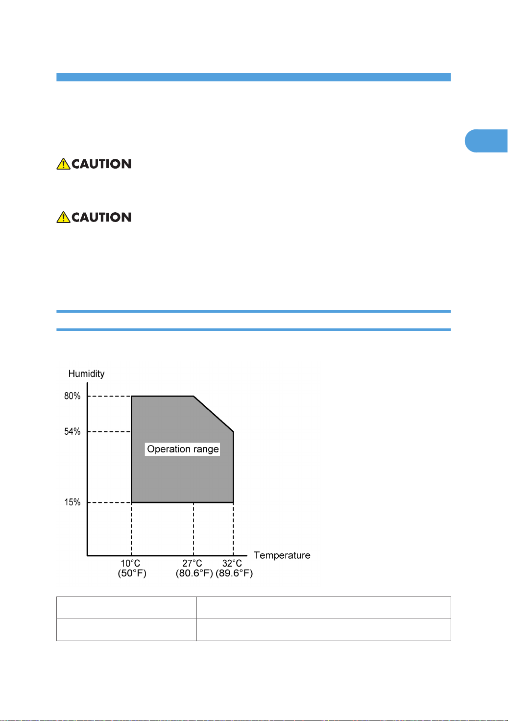
Environment
–Temperature and Humidity Chart–
• Temperature Range: 10°C to 32°C (50°F to 89.6°F)
• Humidity Range: 15% to 80% RH
13
Page 15

1. Installation
1
• Ambient Illumination: Less than 1,500 lux (do not expose to direct sunlight)
• Ventilation: 3 times/hr/person or more
• Ambient Dust: Less than 0.1 mg/m3 (2.7 x 10⁻⁶ oz/yd3)
• Avoid areas exposed to sudden temperature changes:
1) Areas directly exposed to cool air from an air conditioner.
2) Areas directly exposed to heat from a heater.
• Do not place the machine in areas where it can get exposed to corrosive gases.
• Do not install the machine at any location over 2,000 m (6,500 ft.) above sea level.
• Place the machine on a strong and level base. (Inclination on any side should be no more than 5
mm.)
• Do not place the machine where it is subjected to strong vibrations.
Machine Level
Front to back: Within 5 mm (0.2") of level
Right to left: Within 5 mm (0.2") of level
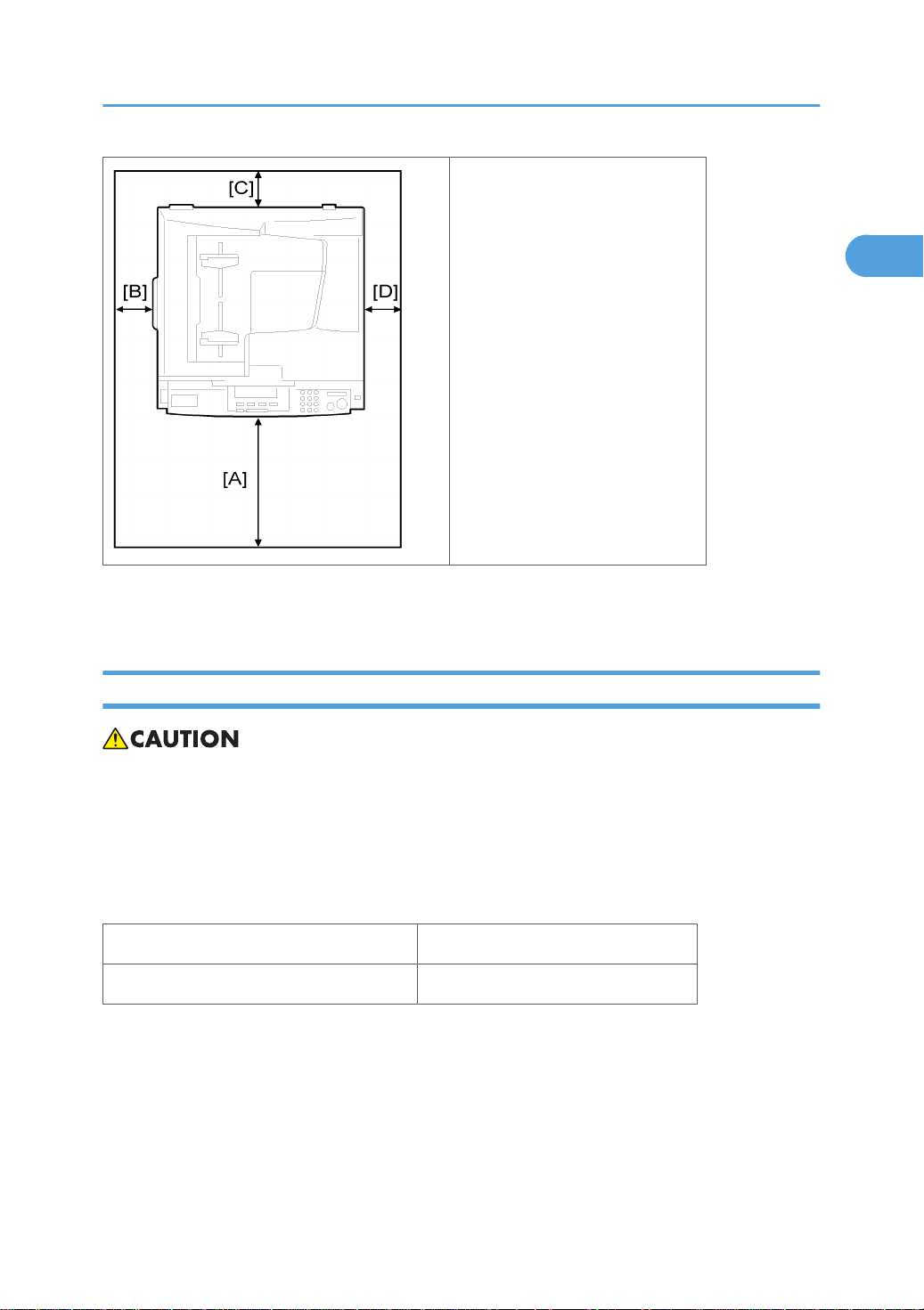
Minimum Space Requirements
Place the copier near the power source, providing clearance as shown:
14
Page 16
Installation Requirements
1
A (front): 750 mm (30")
B (left): 150 mm (6")
C (rear): 50 mm (2")
D (right): 250 mm (10")
The recommended 750 mm front space is sufficient to allow the paper tray to be pulled out. Additional
front space is required to allow operators to stand at the front of the machine.
Power Requirements
• Make sure that the wall outlet is near the machine and easily accessible. After. completing installation,
make sure the plug fits firmly into the outlet.
• Avoid multi-wiring.
• Be sure to ground the machine
Input voltage:
North and South America, Taiwan: 110 – 120 V, 60 Hz, 12 A
Europe, Asia: 220 – 240 V, 50/60 Hz, 7 A
15
Page 17
1. Installation
1
Copier Installation
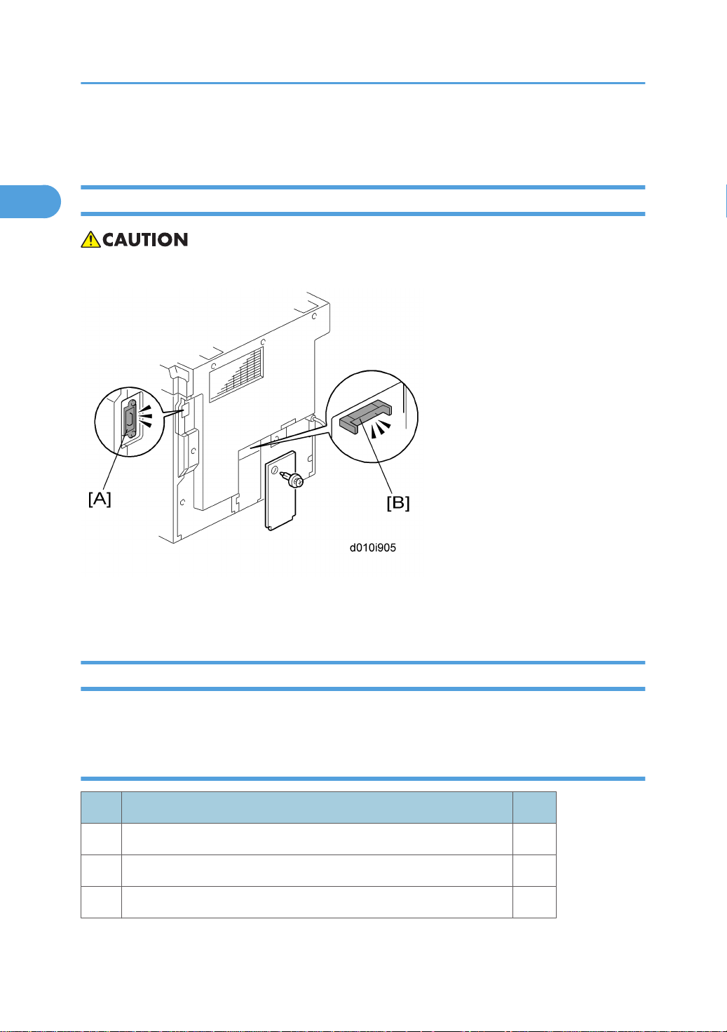
Power Sockets for Peripherals
• Make sure to plug the cables into the correct sockets.
[A]: Socket for ARDF (Rated voltage output max. DC24 V)
[B]: Socket for paper tray unit (Rated voltage output max. DC24 V)
Accessory Check
Check that you have the accessories in this list.
D010
No. Description Q’ty
1 NECR-English (-17) 1
2 EU Safety Sheet (-26, -27) 1
3 Operating Instructions - Book (-17, -19, -21, -29) 1
16
Page 18
No. Description Q’ty
1
4 Operating Instructions - CD-ROM (-17, -19, -21, -29) 1
5 Language Kit (-26, -27) 1
6 Model Name Plate (-29) 1
7 Emblem Cover (-29) 1
D043
No. Description Q’ty
1 Operating Instructions - Book 1
2 Operating Instructions - CD-ROM 1
3 Model Name Plate (-29) 1
Copier Installation
4 Emblem Cover (-29) 1
5 Caution Sheet - CD-Driver (-29) 1
6 Sheet -EULA 1
Installation Procedure
• Unplug the machine power cord before starting the following procedure.
17
Page 19

1. Installation
1
1. Remove filament tape and other padding.
2. Open the front door and remove the toner bottle holder [A].
18
Page 20
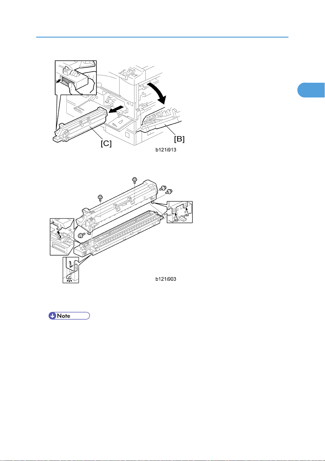
3. Open the right door [B], and remove the PCU (photo conductor unit) [C].
1
Copier Installation
4. Separate the PCU into the upper part and the lower part ( x 5).
5. Put a sheet of paper on a level surface and place the upper part on it.
• This prevents foreign material from getting on the sleeve rollers
19
Page 21
1. Installation
1
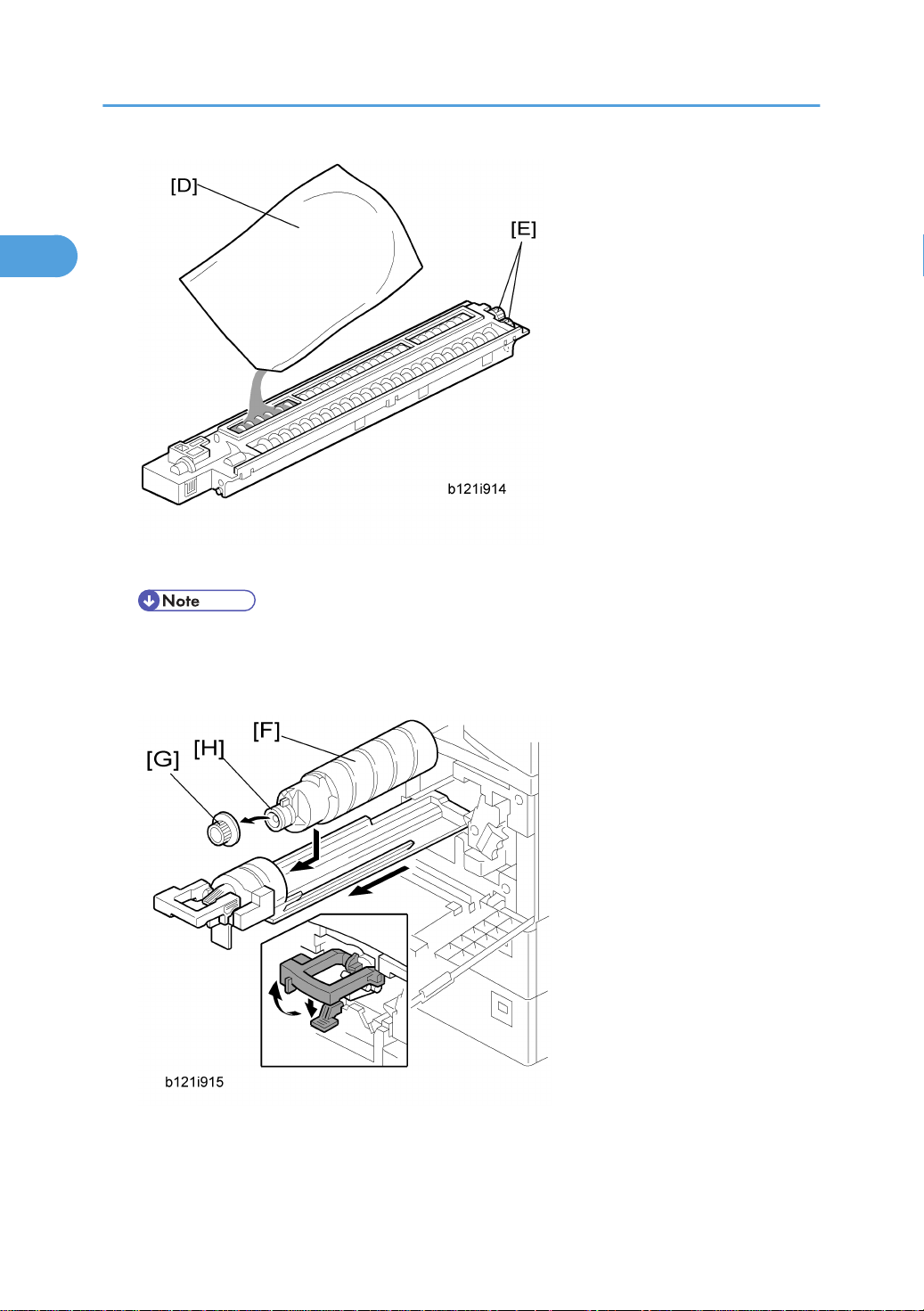
6. Distribute a pack of developer [D] to all openings equally.
• Do not spill the developer on the gears [E]. If you have spilled it, remove the developer by using
a magnet or magnetized screwdriver.
• Do not turn the gear [E] too much. The developer may spill.
7. Reassemble the PCU and reinstall it.
8. Shake the toner bottle [F] several times. (Do not remove the bottle cap [G] before you shake the bottle.)
20
Page 22

Copier Installation
1
9. Remove the bottle cap [G] and install the bottle on the holder. (Do not touch the inner cap [H].)
10. Set the holder (with the toner bottle) in the machine.
11. Pull out the paper tray [I] and adjust the positions of the end and side guides.
• To move the side guides, release the green lock on the rear side guide.
12. Install the optional ARDF or platen cover.
13. Plug in the main power cord and turn on the main switch.
14. Activate the SP mode and execute "Devlpr Initialize" (SP 3016-1).
15. Wait until the message "Completed" shows (about 45 seconds).
16. Activate the User Tools and select the menu "Language."
17. Specify a language. This language is used for the operation panel.
18. Load the paper in the paper tray and make a full size copy, and make sure the side-to-side and
leading edge registrations are correct.
21
Page 23
1. Installation
1
Platen Cover Installation
Accessory Check
Check that you have the accessories indicated below.
No. Description Q’ty
1 Stepped Screw 2
Installation Procedure
• Unplug the machine power cord before starting the following procedure.
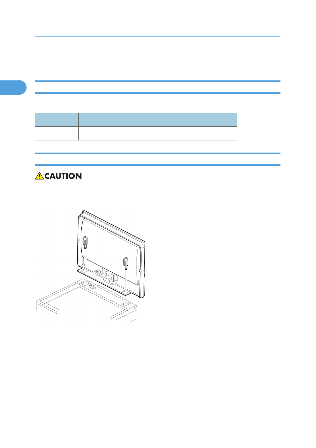
Install the platen cover ( x 2).
22
Page 24

ARDF Installation
1
Accessory Check
Check the quantity and condition of the accessories against the following list.
No. Description Q’ty
1 Scale Guide 1
2 DF Exposure Glass 1
3 Stud Screw 2
4 Knob Screw 2
5 Original Size Decal 2
6 Screwdriver Tool 1
ARDF Installation
7 Attention Decal – Top Cover 1
8 Attention Decal – Scanner 1
9 Cloth Holder 1
10 Cloth 1
11 Spacer*1 2
*1: These spacers are used for adjusting the trapezoid image.
23
Page 25
1. Installation
1
Installation Procedure
• Unplug the copier power cord before starting the following procedure.
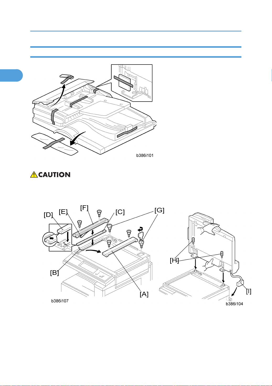
1. Remove the strips of tape.
2. Remove the left scale [A] ( x 2).
3. Peel off the backing [B] of the double-sided tape attached to the glass holder.
4. Place the DF exposure glass [C] on the glass holder.
24
Page 26
ARDF Installation
1
• When installing the DF exposure glass, make sure that the painted mark [D] is placed to the
downward, as shown.
5. Peel off the backing [E] of the double-sided tape attached to the rear side of the scale guide [F], then
install it ( x 2 removed in step 2).
6. Install the two stud screws [G].
7. Mount the DF on the copier, then slide the DF to the front as shown.
8. Secure the DF unit with two screws [H].
9. Connect the cable [I] to the copier.
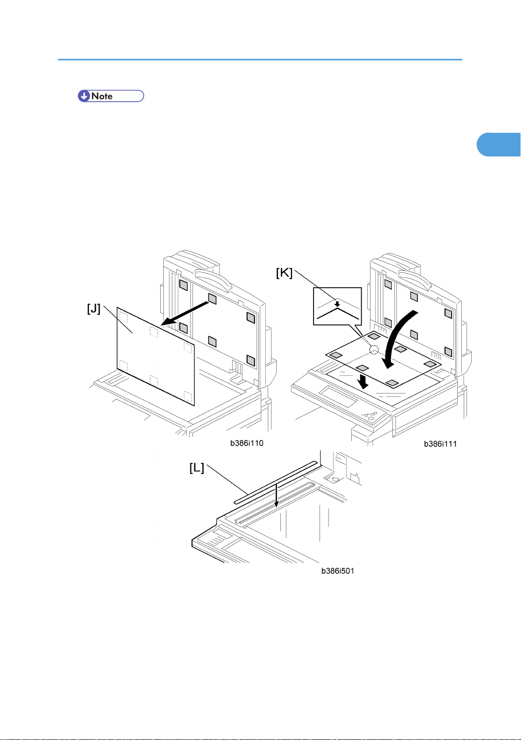
10. Peel off the platen sheet [J] and place it on the exposure glass.
11. Line up the rear left corner of the platen sheet flush against corner [K] on the exposure glass.
12. Close the ARDF.
13. Attach the appropriate scale decal [L] as shown.
25
Page 27
1. Installation
1
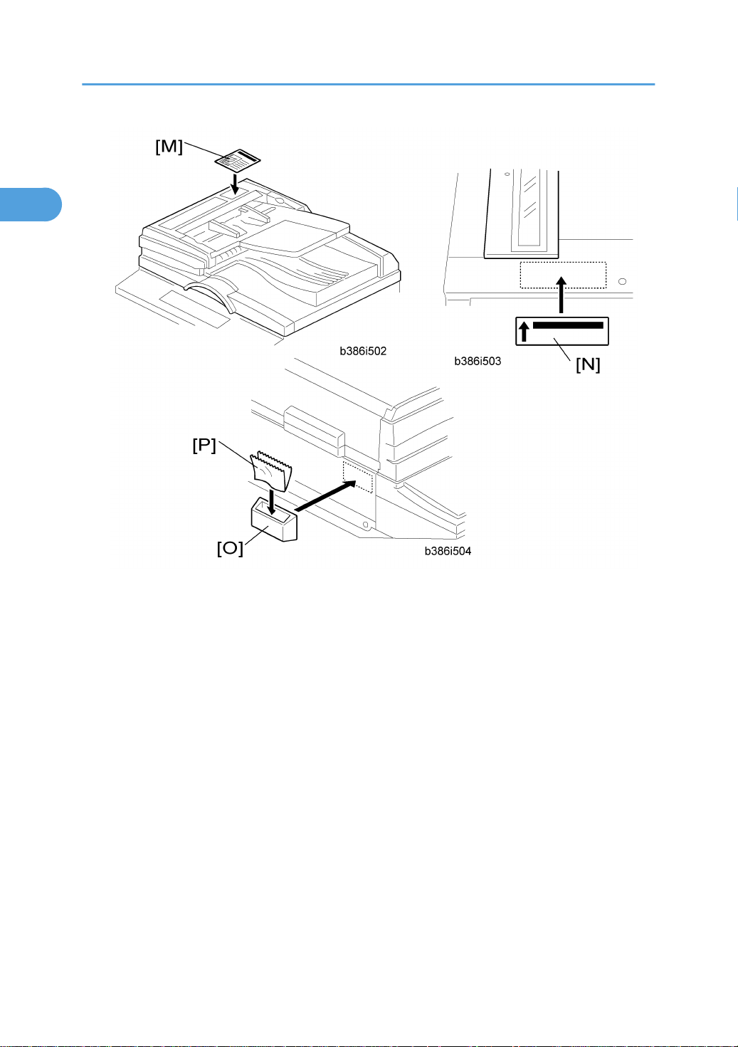
14. Attach the decal [M] to the top cover as shown, choosing the language most suitable for the machine
installed.
15. Line up arrow on the decal [N] with the center of the ADF exposure glass as shown, and attach it to
the cover. As with step 14, choose the language most suitable for the machine installed.
16. Attach the cloth holder [O] to the left side of the scanner as shown.
17. Insert the cloth [P] in the cloth holder.
18. Turn the main power switch on. Then check if the document feeder works properly.
19. Make a full size copy. Then check to make sure the registrations (side-to-side and leading edge) and
image skew are correct. If they are not, adjust the registrations and image skew (refer to the service
manual).
26
Page 28
Two-tray Paper Tray Unit Installation
1
Two-tray Paper Tray Unit Installation
Accessory Check
Check the quantity and condition of the accessories against the following list.
No. Description Q’ty
1 Securing Bracket 2
2 Screw - M4 x 8 4
Installation Procedure
• Unplug the machine power cord before starting the following procedure.
• The handles of the main machine for lifting must be inserted inside the machine and locked unless
these handles are used for the installation or relocation of the main machine.
1. Remove the strips of tape.
27
Page 29
1. Installation
1
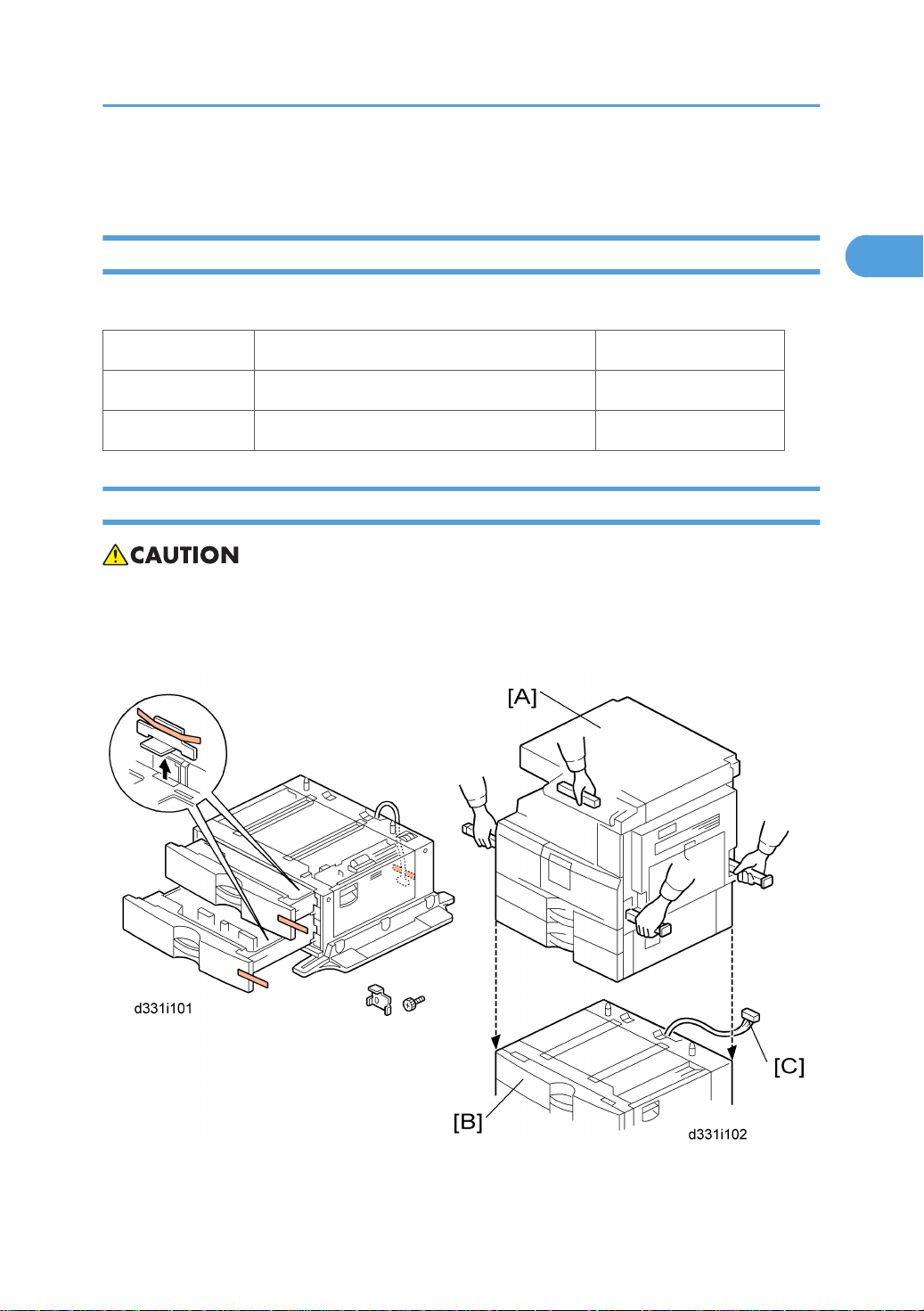
2. Set the copier [A] on the paper tray unit [B].
• When installing the copier, be careful not to pinch the cable [C].
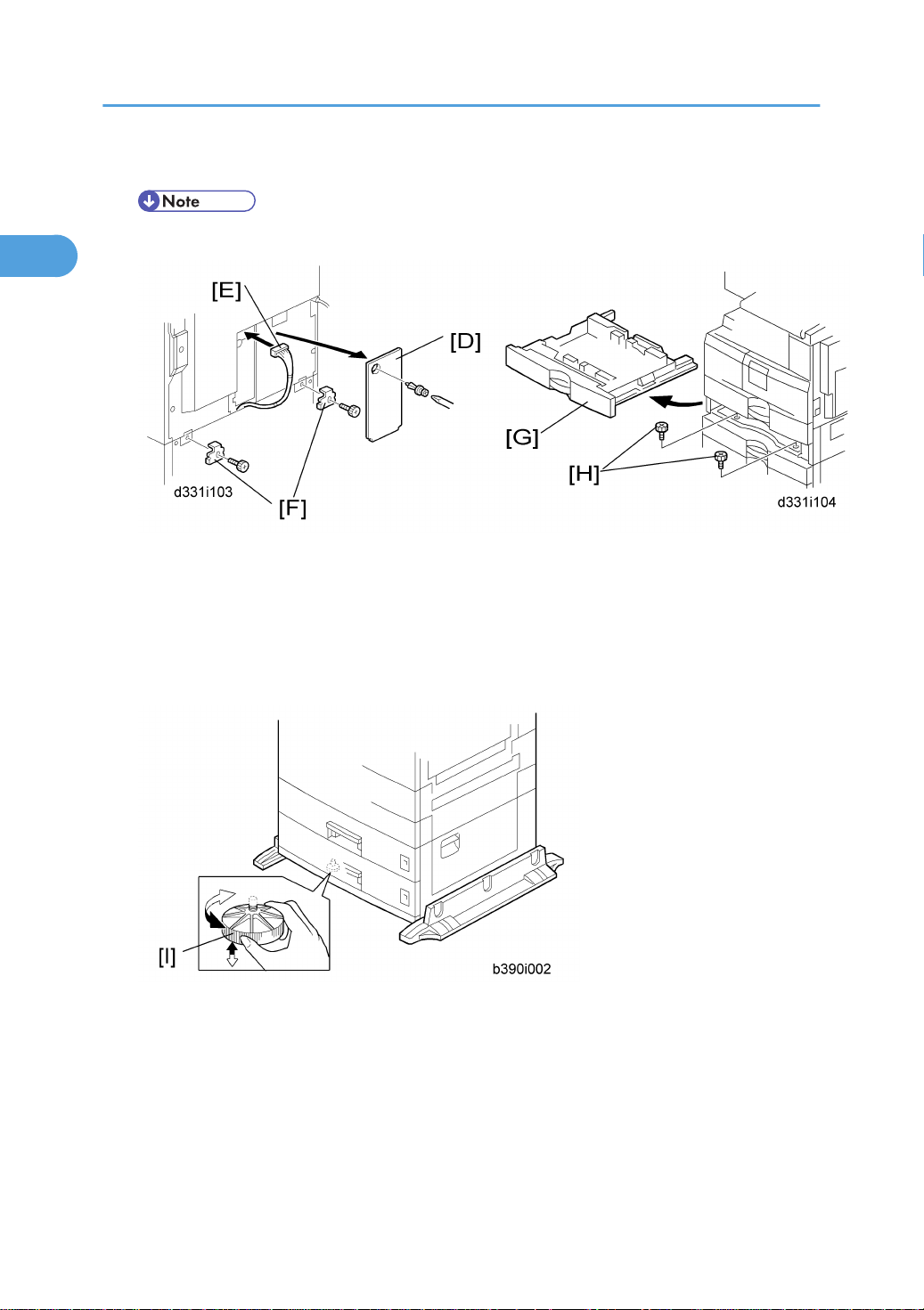
3. Remove the connector cover [D] (rivet screw x 1).
4. Connect the cable [E] to the copier, as shown.
5. Attach a securing bracket [F] to each side of the paper tray unit, as shown ( x 1 each).
6. Re-install the connector cover.
7. Remove the 2nd paper tray [G] and secure the paper tray unit with two screws [H].
8. Reinstall the 2nd paper tray.
9. Rotate the adjuster [I] until the machine cannot be pushed across the floor.
10. Loads paper into the paper trays and select the proper paper size.
11. Turn on the main switch.
12. Check the machine’s operation and copy quality.
28
Page 30
One-Bin Tray Installation
1
Accessory Check
Check the quantity and condition of the accessories.
No. Description Q’ty
1 Installation procedure 1
2 One-bin sorter 1
3 Exit tray 1
4 Tapping screw M3 x 6 1
Installation Procedure
One-Bin Tray Installation
• Unplug the machine power cord before starting the following procedure.
1. Remove the inverter tray [A].
2. Remove the rail [B] (2 knob screws).
3. Remove the sorter cap [C] (1 rivet).
29
Page 31

1. Installation
1
4. Open the front cover [D].
5. Remove the front right cover [E] ( x 1).
6. Disconnect the connector [F].
7. Cut the front cover and make an opening [G] for the 1-bin sorter.
8. Install the 1-bin sorter [H].
30
Page 32

• Make sure the connector [I] is connected firmly.
1
9. Fasten the screw.
10. Connect the connector [J] you have removed in step 6.
• Make sure that the connector is connected.
One-Bin Tray Installation
11. Reassemble the front right cover [K].
12. Close the front cover [L].
13. Install the exit tray [M] as follows:
• Keep the front end higher than the rear end.
• Push the left hook into the opening of the copier.
• Push the right hook into the opening of the copier.
14. Pull the support [N] out of the left end of the exit tray.
15. Insert the support into the left end of the paper exit tray [O] (of the copier).
16. Turn the main switch on.
17. Check the operation.
31
Page 33

1. Installation
1
Bridge Unit Installation
Component Check
No. Description Q’ty
1 Bridge Unit 1
2 Tapping screw: M3 x 6 1
3 Tapping screw: M3 x 8 2
4 Holder bracket 1
Installation Procedure
• Unplug the copier power cord before starting the following procedure.
32
Page 34

Bridge Unit Installation
1
• If you install the 1-bin tray (D339) to the machine, install the 1-bin tray first before installing the bridge
unit (D340).
• If you install the finisher unit (B792) to the machine, install the finisher unit after installing the bridge
unit (D340).
Installation for a machine WITHOUT the 1-bin tray unit
1. Remove the inverter tray [A].
2. Remove the rail [B] (knob screw x 2).
3. Remove the inner cover right [C] (rivet screw x 1).
33
Page 35

1. Installation
1
4. Remove the inner cover left [D] ( x 2).
5. Remove the inner tray [E] ( x 1).
6. Open the front door [F].
7. Remove the front right cover [G] ( x 1).
8. Cut off the cutouts (3 pieces) [H] with nippers.
9. Remove the left upper cover [I] ( x 2).
10. Install the bridge unit [J] to the machine (Front side: (M3x8) x 2, Rear side: (M3x6) x 1).
11. Connect the cables [K] to the machine ( x 2).
12. Reinstall the left upper cover ( x 2).
13. Reinstall the inner cover right if 1-bin tray unit is not installed (rivet screw x 1).
34
Page 36

Bridge Unit Installation
1
14. Reinstall the inner cover left ( x 2).
15. Install the holder bracket [L]
• The holder bracket [L] is necessary when the finisher is installed. Do not tighten it with a screw at
this time.
16. Reinstall the rail (knob screw x 2) and inverter tray.
17. Reinstall the front right cover in the machine ( x 1), and then close the front door of the machine.
18. Install the optional finisher (refer to the finisher installation procedure).
19. Turn on the main power switch of the machine.
20. Check the bridge unit operation.
Installation for a machine WITH the 1-bin tray unit
1. Remove the inverter tray and rail (see the steps 1 and 2 in "Installation for a machine WITHOUT the
1-bin tray unit").
2. Remove the exit tray [A].
3. Remove the inner cover left (* step 4 in "Installation for a machine WITHOUT the 1-bin tray unit").
4. Open the front door (* step 6 in "Installation for a machine WITHOUT the 1-bin tray unit").
5. Remove the front right cover (* step 7 in "Installation for a machine WITHOUT the 1-bin tray unit").
6. Cut off the cutouts (4 pieces) with nippers (* step 8 in "Installation for a machine WITHOUT the 1bin tray unit").
35
Page 37

1. Installation
1
7. Open the 1-bin tray [B] as shown.
8. Install the bridge unit [C] holding down the guide plate [D] (Front side: (M3x8) x 2, Rear side:
(M3x6) x 1).
9. Close the 1-bin tray.
10. Reinstall the exit tray to the machine.
11. Do the same steps from 9 to 20 in "Installation for a machine WITHOUT the 1-bin tray unit".
36
Page 38

500-Sheet Finisher (B792)
1
Accessory Check
Check the quantity and condition of the accessories against the following list.
No. Description Q’ty
1 Output Tray 1
2 Unit Holder 1
3 Support Bracket* 2
4 Support Bracket Cover* 2
5 Screws: M3 x 8* 2
6 Screws: M4 x 16* 4
500-Sheet Finisher (B792)
7 Knob screws 4
8 Snap Rings 2
9 Bracket Cover 1
10 Paper Guide 1
*: Four of the items below (No. 3 to 6) are not used for these models (D010/D043).
37
Page 39

1. Installation
1
Installation Procedure
• Unplug the main machine power cord before starting the following procedure.
• Before you install the 500-sheet finisher, the optional bridge unit (D340) must be installed.
38
Page 40

Installation of the 500-Sheet Finisher
1
1. Unpack the finisher and remove all tapes and retainers.
500-Sheet Finisher (B792)
2. Cut off the cutout [A] with nippers.
3. Attach the paper guide [B] to the bridge unit.
• Make sure to pass the mylar through the opening in the paper guide [C].
4. Attach the holder bracket [D] and the unit holder [E] (knob screw x 4).
• The holder bracket [D] must be placed inside the unit holder [E]. The holder bracket is provided
with the bridge unit (D340).
39
Page 41

1. Installation
1
5. Install the 500-sheet finisher [F] on the machine ( x 1).
6. Attach the bracket cover [G].
7. Install the output tray [H] on the 500-sheet finisher (2 snap rings).
8. Pull out the tray extension [I] of the bridge unit.
9. Turn on the main power switch, and then check the finisher operation.
40
Page 42

Anti-condensation Heater Installation
1
Anti-condensation Heater Installation
• Unplug the machine power cord before starting the following procedure.
1. Remove the exposure glass.
2. Remove the left cover.
3. Pass the connector [A] through the opening [B].
4. Install the anti-condensation heater [C], as shown.
5. Join the connectors [A, D].
6. Clamp the harness with the clamp [E].
7. Reinstall the left cover and exposure glass.
8. Attach the decal to the left side of the machine's main switch.
41
Page 43

1. Installation
1
Tray Heaters
• Unplug the machine power cord before starting the following procedure.
Tray Heater
42
1. Remove the 1st and 2nd tray cassettes.
2. Remove the rear cover [A] ( x 8).
3. Place the tray heater on the bottom frame inside the machine and pass the heater harness [B] through
the opening [C] of the rear frame.
4. Attach the tray heater [D] to the bottom frame ( x 1).
Page 44

5. Remove the harness cap [E] of the machine.
1
Tray Heaters
6. Connect the harness [F] of the heater to the harness [G] of the machine.
7. Reinstall the rear cover and all tray cassettes/
8. Attach the power decal to the left side of the machine's main switch.
Tray Heaters for the Optional Paper Feed Unit
1. Remove the rear cover of the main machine.
2. Pull out the all tray cassettes of the paper tray unit.
43
Page 45

1. Installation
1
3. Remove the rear cover [A].for the paper tray unit
4. Remove the cable guide [B].
44
Page 46

5. Pass the connector [C] through the opening [D].
1
6. Install the tray heater [E] ( x 1)
Tray Heaters
7. Clamp the cables [F], as shown.
8. Remove the harness cap [G] of the machine.
9. Join the connectors [G] [H].
10. Reinstall the cable guide and rear cover of the paper tray unit.
11. Reinstall the all tray cassettes.
45
Page 47

1. Installation
1
12. Remove the heater harness cover [I] (rivet screw x 1).
13. Turn the heater harness cover upside down and reinstall it in the rear cover of the main machine.
• Make sure that cutout [J] is directed to the downward. Otherwise, the rear cover of the main
machine pinches the heater harness and breaks it.
14. Reinstall the rear cover of the main machine.
15. Attach the power decal to the left side of the machine's main switch if it has not been attached.
46
Page 48

Key Counter Interface Installation
1
• Unplug the machine power cord before starting the following procedure.
Key Counter Interface Installation
1. Remove the rear cover [A] ( x 8).
2. Install the four standoffs [B] in the four holes [C] on the crosspiece.
3. Attach the bridge board [C].
47
Page 49

1. Installation
1
4. Connect the one side [D] of the harness to CN140 (13 pins) on the BICU and the other side [E] of
the harness to CN3 on the bridge board.
5. Clamp the harness ( x 4).
6. Reassemble the rear cover.
48
Page 50

GDI Expansion
1
Accessory Check
No. Description Q’ty
1 Cover-CPS NA 1
2 Cover-CPS EU 1
3 Tapping Screw-M3X6 6
4 Sheet-EULA 1
5 Seal-Caution 1
6 Installation Procedure 1
7 PCL Dongle (-57) 1
GDI Expansion
Installing Expansion Component
• Unplug the machine power cord before starting the following procedure.
1. Remove the rear cover [A] ( x 8).
49
Page 51

1. Installation
1
2. Remove the interface cover [B].
3. Remove one screw [C] from the BICU.
4. Connect the controller box [D] to the BICU ( x 7).
Make sure that the BICU [E] is not damaged and that the three openings [F][G][H] hold the controller
box.
5. Re-attach the rear cover ( x 8).
Installing Panels and Keys
1. Remove the dummy cover [A] from the operation panel.
50
Page 52

2. Install the printer/scanner panel [B] on the operation panel.
1
GDI Expansion
51
Page 53

1. Installation
1
PCL Option
Accessory Check
No. Description Q’ty
1 PCL Dongle 1
Installing PCL Option
• Before installing the PCL option, download the firmware (D3265502) from the firmware download
site into the IC card, which you have.
• Unplug the machine power cord before starting the following procedure.
• Before you install the PCL, the GDI expansion (D326-17) must be installed.
1. Remove the rear cover (* "Rear Cover" in the section "Replacement and Adjustment").
52
Page 54

PCL Option
1
2. Remove the GDI box left cover [A] ( x 7).
3. Remove the GDI box cover [B] ( x 7).
53
Page 55

1. Installation
1
4. Install the PCL dongle [C] in the GDI board socket as shown above.
5. Turn on the DipSW2 [D] switch (upper position).
6. Remove the cover of the IC card slot on the GDI controller board.
54
Page 56

7. Install the PCL IC card in the IC card sot.
1
8. Turn on the main power switch.
PCL Option
• LED7 (orange) blinks during this installation.
• LED6 (red) lights after completion of this installation.
9. Turn off the main power switch after completing the installation.
10. Turn off the Dip SW2 (lower position).
11. Reassemble the machine.
12. Turn on the main power switch.
13. Output the "Config. Page" (UserTool > Printer Features > List/Test Print > Config. Page) and confirm
if PCL option is correctly installed.
• This installation procedure is not necessary for PCL updating once the PCL option has been installed
in the GDI controller. In PCL updating, you can see the installation procedure on the LCD after installing
the PCL option IC card in the IC card slot.
55
Page 57

1. Installation
1
Mechanical Counter
Component Check
No. Description Q’ty
1 Mechanical counter 1
Installing Mechanical Counter
• Unplug the machine power cord before starting the following procedure.
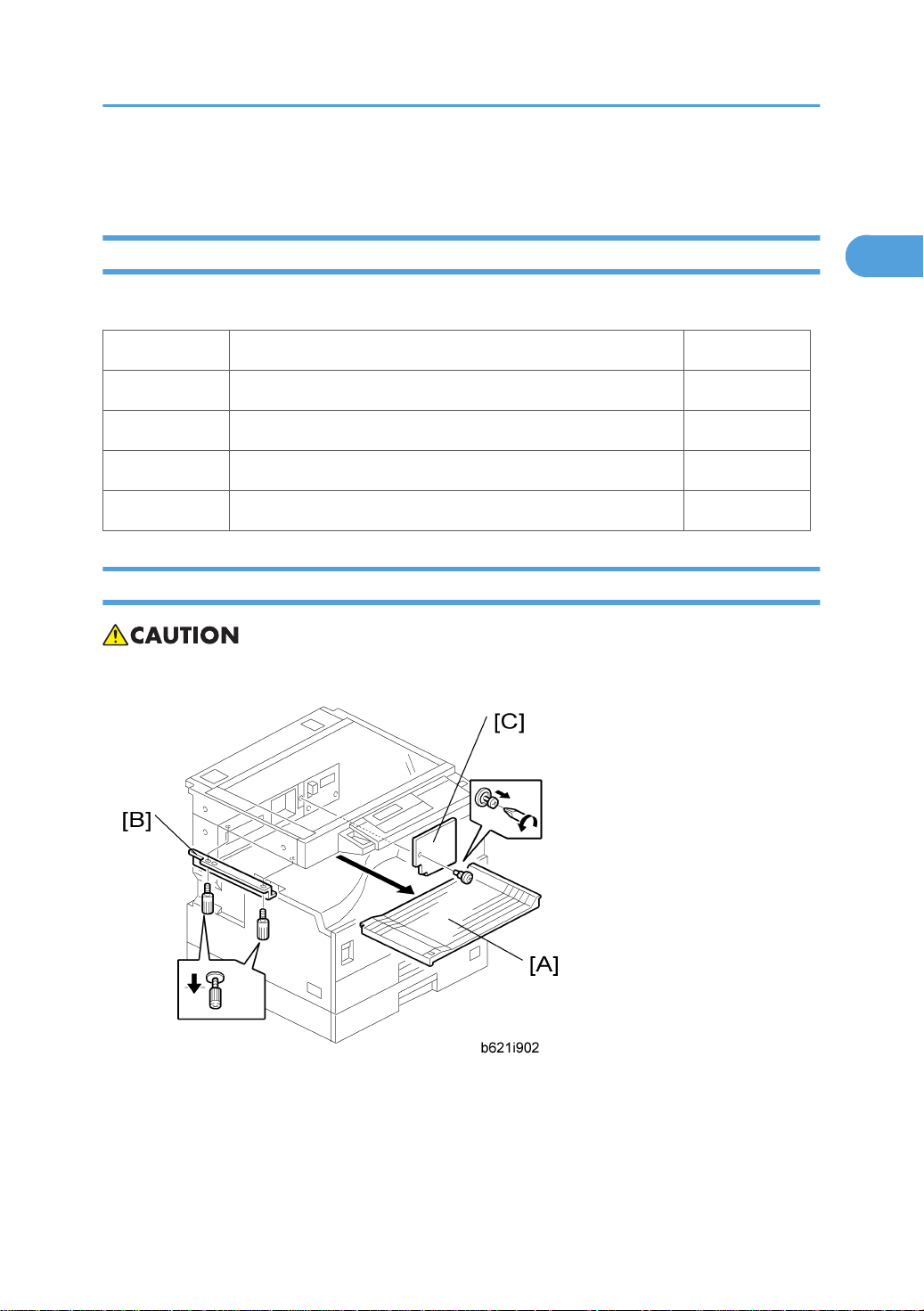
1. Remove the copy tray [A] ( x 1, hooks).
2. Remove the inner cover [B] ( x 2, hooks).
56
Page 58

3. Open the front door [C].
1
4. Remove the front cover [D] ( x 3).
Mechanical Counter
5. Cut off the cutout [E] of the front cover with nippers.
57
Page 59

1. Installation
1
6. Install the mechanical counter [F] into the counter slot [G] ( x 1).
• When you install the mechanical counter, make sure that the circle mark [H] is placed downward.
7. Reassemble the machine.
58
Page 60

When removing the mechanical counter
1
When removing the mechanical counter, first release the hook [A], and then pull it out.
Mechanical Counter
59
Page 61

1. Installation
1
60
Page 62

2. Preventive Maintenance
2
PM Tables
• After preventive maintenance work, reset the PM counter (SP 7804-1).
• PM intervals (60k, 120K and 600K) indicate the number of prints.
Key: AN: As necessary, C: Clean, R: Replace, L: Lubricate, I: Inspect
Optics
EM 60k 120k AN NOTE
Reflector C Optics cloth
1st mirror C C Optics cloth
2nd mirror C C Optics cloth
3rd mirror C C Optics cloth
Scanner guide rails C Do not use alcohol.
Replace the platen sheet if
Platen cover I C
Exposure glass C C Blower brush or alcohol
Toner shield glass C Blower brush
APS sensors C Blower brush
necessary.
Blower brush or alcohol
Drum Area
EM 60k 120k 600k AN NOTE
PCU I R
Drum R
61
Page 63

2. Preventive Maintenance
2
EM 60k 120k 600k AN NOTE
Developer R
Charge roller R
Cleaning brush (charge roller) R
Cleaning blade (OPC drum) R
Pick-off pawls (OPC drum) R
Transfer roller R
Discharge Plate R
ID sensor C C Blower brush
Paper Feed
EM 60k 120k AN NOTE
Paper feed roller (each tray) C R C Clean with water or alcohol.
Friction pad (each tray) C R C Clean with water or alcohol.
Bottom-plate pad (each tray) C C Clean with water or alcohol.
Paper feed roller (bypass tray) C C Clean with water or alcohol.
Friction pad (bypass tray) C C Clean with water or alcohol.
Bottom-plate pad (by-pass tray) C C Clean with water or alcohol.
Registration rollers C C Clean with water or alcohol.
Relay rollers C C Clean with water or alcohol.
Paper feed guides C C Clean with water or alcohol.
Paper-dust Mylar C C Clean with water or alcohol.
62
Page 64

Fusing Unit
2
EM 60k 120k AN NOTE
Hot roller R/L S552R
Pressure roller R
Pressure roller cleaning roller R A cleaner and alcohol
Hot roller bushings I/L C S552R
Pressure roller bushing R C
Hot roller stripper pawls R C Dry cloth
Thermistor R C Dry cloth
Fusing guide plate C A cleaner and alcohol
Cleaning roller bushing C C Dry cloth
PM Tables
ARDF
EM 80k AN NOTE
Feed belt R C Clean with water or alcohol.
Separation roller R C Clean with water or alcohol.
Pick-up roller R C Clean with water or alcohol.
Stamp R Replace when necessary.
White plate C C Clean with water or alcohol.
DF exposure glass C C Clean with water or alcohol.
Platen cover I C Clean with water or alcohol.
Paper Tray Unit
60k 120k AN NOTE
Paper feed rollers R C Dry or damp cloth
63
Page 65

2. Preventive Maintenance
2
60k 120k AN NOTE
Bottom-plate pads C C Dry cloth
Paper-feed guides C C Clean with water or alcohol.
Friction pads R C Dry or damp cloth
Relay clutch I
Feed clutches I
Relay roller C C Dry cloth
64
Page 66

How to Reset the PM Counter
2
After preventive maintenance work, reset the PM counter (SP 7804-1) as follows.
How to Reset the PM Counter
Activate the SP mode (* "Service Program Mode").
1. Select SP 7804-1 (Reset–PM Counter).
2. Press the OK key [A]. The message "Execute" shows.
3. Press the button [B] below the message "Execute."
65
Page 67

2. Preventive Maintenance
2
4. The messages "Execute?" followed by "Cancel" and "Execute" show.
5. To reset the PM counter, press the button [C] below the message "Execute."
6. Wait until the message "Completed" shows.
7. Quit the SP mode.
66
Page 68

3. Replacement and Adjustment
3
General Cautions
Do not turn off the main switch while any of the electrical components are active. Doing so may result in
damage to units (such as the PCU) as they are pulled out or replaced.
PCU (Photoconductor Unit)
The PCU consists of the OPC drum, charge roller, development unit, and cleaning components. Observe
the following precautions when handling the PCU.
1. Never touch the drum surface with bare hands. If the drum surface is dirty or if you have accidentally
touched it, wipe it with a dry cloth, or clean it with wet cotton and then wipe it dry with a cloth.
2. Never use alcohol to clean the drum. Alcohol will dissolve the drum surface.
3. Store the PCU in a cool dry place.
4. Do not expose the drum to corrosive gases (ammonia, etc.).
5. Do not shake a used PCU, as this may cause toner and developer to spill out.
6. Dispose of used PCU components in accordance with local regulations.
• You must run SP 3016-1 to initialize the TD sensor after you install a new PCU. After starting
initialization, be sure to wait for it to reach completion (wait for the motor to stop) before you re-open
the front cover or turn off the main switch.
Transfer Roller
1. Never touch the surface of the transfer roller with bare hands.
2. Be careful not to scratch the transfer roller, as the surface is easily damaged.
Scanner Unit
1. Use alcohol or glass cleaner to clean the exposure and scanning glass. This will reduce the static
charge on the glass.
2. Use a blower brush or a water-moistened cotton pad to clean the mirrors and lenses.
3. Make sure to not bend or crease the exposure lamp’s ribbon cable.
4. Do not disassemble the lens unit. This will cause the lens and copy image to get out of focus.
67
Page 69

3. Replacement and Adjustment
3
5. Do not turn any of the CCD positioning screws. This will put the CCD out of position.
Laser Unit
1. Do not loosen or adjust the screws securing the LD drive board on the LD unit. This will put the LD unit
out of adjustment.
2. Do not adjust the variable resistors on the LD unit. These are adjusted at the factory.
3. The polygonal mirror and F-theta lens are very sensitive to dust.
4. Do not touch the toner shield glass or the surface of the polygonal mirror with bare hands.
Fusing Unit
1. After installing the fusing thermistor, make sure that it is in contact with the hot roller and that the roller
can rotate freely.
2. Be careful to avoid damage to the hot roller stripper pawls and their tension springs.
3. Do not touch the fusing lamp and rollers with bare hands.
4. Make sure that the fusing lamp is positioned correctly and that it does not touch the inner surface of
the hot roller.
Paper Feed
1. Do not touch the surface of the paper feed rollers.
2. To avoid misfeeds, the side and end fences in each paper tray must be positioned correctly so as to
align with the actual paper size.
3. The paper trays have interchangeability as following.
Standard Option
1st tray 2nd tray 3rd tray 4th tray
1st tray Yes No No No
Standard
2nd tray No Yes No No
3rd tray No No Yes Yes
Option
4th tray No No Yes Yes
68
Page 70

General Cautions
3
• If the optional tray heater or optics anti-condensation heater is installed, keep the machine's power
cord plugged in even while the main switch is off, to keep the heater(s) energized.
69
Page 71

3. Replacement and Adjustment
3
Special Tools and Lubricants
Part Number Description Q’ty
A0069104 Scanner Positioning Pins (4 pins/set) 1 set
A2929500 Test Chart S5S (10 pcs/set) 1 set
VSSM9000 FLUKE 87 Digital Multimeter 1
N8036701 4MB Flash Memory Card 1
A2579300 Grease Barrierta S552R 1
52039502 Grease G-501 1
70
Page 72

Exterior Covers and Operation Panel
3
Exterior Covers and Operation Panel
Rear Cover
1. Unplug the DF cable (if installed).
2. Rear cover [A] ( x 8)
Tray Harness Cover
1. Tray harness cover [A] (1 rivet)
71
Page 73

3. Replacement and Adjustment
3
Copy Tray
1. Copy tray [A] ( x 1、hook x 1)
Inner Cover
1. Copy tray (* "Copy Tray")
2. Inner cover [A] ( x 2)
72
Page 74

Upper Covers
3
1. Platen Cover, ARDF, or ADF (if installed)
2. Rear cover (* "Rear Cover")
Exterior Covers and Operation Panel
3. Front upper left cover [A] ( x 3)
4. Left upper cover [B] ( x 2)
5. Operation panel [C] ( x 4, x 1)
6. Right upper cover [D] ( x 1, 3 hooks)
• Push the cover to the rear side to release the hooks.
7. Top rear cover [E] ( x 1)
73
Page 75

3. Replacement and Adjustment
3
Left Cover
1. Left cover [A] ( x 5)
Front Cover
1. Pull out the (top) paper tray.
2. Open the front door [A].
3. Front cover [B] ( x 3)
74
Page 76

Front Right Cover
3
1. Open the front door [A].
Exterior Covers and Operation Panel
2. Front right cover [B] ( x 1)
Right Rear Cover
1. Right upper cover (* "Upper Covers")
2. Open the duplex unit.
75
Page 77

3. Replacement and Adjustment
3
3. Right rear cover [A] ( x 2)
Right Door (Duplex Unit)
1. Rear cover (* "Rear Cover")
2. Open the right door [A].
3. Release the spring and chain.
4. Open the clamps [B] and disconnect the three connectors [C].
5. Right door [A]
76
Page 78

By-pass Tray
3
Exterior Covers and Operation Panel
1. Right rear cover (* "Right Rear Cover")
2. Open the right door.
3. Release the by-pass tray cable from the clamps (see [B] in the preceding procedure "Right Door")
and disconnect the connector (5-pin connector with colored wires).
4. Cable holder [A]
5. Front-side clip ring [B]
6. Front-side pin [C] (You can push the pin from behind the right door.)
7. Front-side tray holder arm [D]
8. Remove the rear-side clip ring, pin, and tray holder arm in the same manner.
9. By-pass tray [E]
77
Page 79

3. Replacement and Adjustment
3
Right Lower Cover
1. Right lower cover [A] (2 pin)
Platen Cover Sensor
1. Top rear cover (* "Upper Covers")
2. Platen cover sensor [A] ( x 1)
78
Page 80

Scanner Unit
3
Exposure Glass/DF Exposure Glass
Scanner Unit
Exposure Glass
1. Front upper left cover (* "Upper Covers")
2. Left scale [A] ( x 2)
3. Rear scale [B] ( x 3)
4. Exposure glass [C]
• Make sure that the mark is at the rear left corner, and that the left edge is aligned to the support
on the frame when you reinstall the exposure glass.
DF Exposure Glass
1. Front upper left cover (* "Upper Covers")
2. Left scale [A]
3. DF exposure glass [D]
79
Page 81

3. Replacement and Adjustment
3
• Make sure that the yellow mark [E] is on the bottom at the front end when reinstall the exposure
glass.
Lens Block
• Do not touch the paint-locked screws on the lens block. The position of the lens assembly (black part)
is adjusted before shipment.
• Do not grasp the PCB or the lens assembly when you handle the lens block. The lens assembly may
slide out of position.
1. Exposure glass (* "Scanner Unit")
2. Lens cover [A] ( x 5)
3. Disconnect the flat cable [B].
4. Lens block [C] ( x 4)
• Adjust the image quality (* "Copy Adjustments Printing/Scanning") after you install a new lens
block.
80
Page 82

Lamp Stabilizer Board and Exposure Lamp
3
1. Operation panel (* "Upper Covers")
Scanner Unit
2. Exposure glass (* "Exposure Glass/DF Exposure Glass")
3. Slide the first scanner to a position where the front end of the lamp is visible.
4. Place one hand under the lamp stabilizer board [A] and release the hook [B].
5. Lamp stabilizer board ( x 1, flat cable x 1)
6. Press the plastic latch [C] and push the front end of the lamp toward the rear.
7. Lamp [D] (with the cable)
81
Page 83

3. Replacement and Adjustment
3
Original Width/Length Sensor
1. Exposure glass (* "Scanner Unit")
2. Original width sensor [A] ( x 1, x 1)
3. Lens block (* "Scanner Unit")
4. Original length sensor [B] ( x 1, x 1)
82
Page 84

Sensor Positions
3
Scanner Unit
Sensor positions vary according to regions as shown above.
Sensor Positions for China Model (8K/16K)
This procedure is for China models only. You must rearrange the positions of the original width and length
sensors for the copier to detect the following original sizes:
• 8K SEF (270 x 390 mm)
• 16K SEF (195 x 270 mm)
• 16K LEF (270 x 195 mm)
After you have rearranged the positions, the sensors work as listed in the table. Rearrange the sensor
positions as follows:
Original Size Length Sensors Width Sensors
8K-SEF L1 L2 W1 W2
16K-SEF X X X O
83
Page 85

3. Replacement and Adjustment
3
Original Size Length Sensors Width Sensors
16K-LEF X O O O
16K-SEF O O X O
1. Specify SP mode settings:
2. Select SP 4305 1, and specify 2 (=Yes).
The machine will detect 8K/16K rather than A3/A4/B4/B5 (A3-SEF/B4-SEF ⇒ 8K-SEF; B5-SEF/
A4-SEF ⇒ 16K-SEF; B5-LEF/A4-LEF ⇒ 16K-LEF).
3. Turn off the main switch.
4. Exposure glass (* "Scanner Unit").
5. Original width/length sensors [A] [B]
6. Rearrange the sensor positions [C] [D].
7. Turn on the main switch and check the operations.
Scanner Motor
1. Rear cover (* "Rear Cover")
2. Right upper cover (* "Right Upper Cover")
3. Exposure glass (* "Exposure Glass/DF Exposure Glass")
84
Page 86

Scanner Unit
3
4. Duplex fan [A] ( x 2, x 1)
5. Scanner motor [B] ( x 3, x 1, spring x 1, belt x 1)
• Install the belt first, and then set the spring when you reassemble. Fasten the leftmost screw (viewed
from the rear), and fasten the other two screws.
• Adjust the image quality after you install the motor.
Scanner Home Position Sensor
1. Left upper cover, front upper cover, top rear cover (* "Upper Covers")
2. Exposure glass, DF exposure glass (if installed) (* "Exposure Glass/DF Exposure Glass")
3. Disconnect the connector [A].
4. Scanner left lid [B] ( x 7)
5. Sensor tape [C].
6. Scanner home position sensor [D]
85
Page 87

3. Replacement and Adjustment
3
Adjusting Scanner Positions
• Grasp the front and rear ends (not the middle) of the first scanner when you manually move it. The
first scanner may be damaged if you press, push, or pull its middle part.
Overview
Adjust the scanner positions when the first scanner [C] and second scanner [B] are not parallel with the
side frames [A], or, when you have replaced one or more of the scanner belts.
To adjust the scanner positions, do either of the following:
• To adjust the belt contact points on the first scanner (* "Adjusting the First Scanner Contact Points"
below.)
• To adjust the belt contact points on the scanner bracket (* "Adjusting the Second Scanner Contact
Points" below.)
86
Page 88

The two actions above have the same objectives--to align the following holes and marks:
3
• The adjustment holes [E] [G] in the first scanner
• The adjustment holes [E] [G] in the second scanner
Scanner Unit
• The alignment marks [D] [F] on the frames
The scanner positions are correct when these holes and marks are aligned.
87
Page 89

3. Replacement and Adjustment
3
Adjusting the First Scanner Contact Points
1. A(R)DF or platen cover
2. Operation panel, top rear cover (* "Upper Covers").
3. Exposure glass (* "Exposure Glass/DF Exposure Glass")
4. Loosen the 2 screws [A] [F].
5. Slide the 1st and 2nd scanners, or one of them, to align the following holes and marks:
• The adjustment holes in the first scanner
• The adjustment holes in the second scanner
• The alignment marks on the frames
6. Insert the positioning tools [D] [E] through the holes and marks.
7. Check that the scanner belts [B] [C] [G] [H] are properly set between the bracket and the 1st scanner.
8. Tighten the screws [A] [F].
9. Remove the positioning tools.
10. Reassemble the machine and check the operation.
88
Page 90

Adjusting the Second Scanner Contact Points
3
1. A(R)DF or platen cover
2. Operation panel, top rear cover (* "Upper Covers").
3. Exposure glass (* "Exposure Glass/DF Exposure Glass")
Scanner Unit
4. Loosen the 2 screws [F].
5. Slide the 2nd scanner to align the following holes and marks
6. The adjustment holes in the first scanner
7. The adjustment holes in the second scanner
8. The alignment marks on the frames
9. Insert the positioning tools [G] [H] through the holes and marks.
10. Check that the scanner belts are properly set in the brackets.
11. Remove the positioning tools.
12. Reassemble the machine and check the operation.
89
Page 91

3. Replacement and Adjustment
3
Laser Unit
• The laser beam can seriously damage your eyes. Be absolutely sure that the main power switch is off
and that the machine is unplugged before you access the laser unit.
Location of Caution Decal
90
Page 92

Toner Shield Glass
3
1. Open the front door.
Laser Unit
2. Lift the toner cartridge latch [A].
3. Press the toner shield glass cover [B] to the left and pull it out.
4. Pull out the toner shield glass [C].
Laser Unit
1. Toner shield glass (* "Toner Shield Glass")
2. Inner cover (* "Inner Cover")
3. Pull out the (upper) paper tray.
91
Page 93

3. Replacement and Adjustment
3
4. Front cover
5. Laser unit [A] ( x 2, x 4)
• The screw at the left front position [B] is longer than the other three.
LD Unit
• Do not touch the paint-locked screw [A]. The LD position is adjusted before shipment.
1. Laser unit [A]
2. LD unit [B] ( x 1)
• Do not screw the LD unit in too tightly when you install it.
92
Page 94

Polygonal Mirror Motor
3
Laser Unit
1. Laser unit
2. Two rubber bushings [A]
3. Laser unit cover [B] ( x 1)
4. Polygonal mirror motor [C] ( x 4)
5. After reassembling, adjust the image quality (* "Copy Adjustments Printing/Scanning").
Laser Unit Alignment Adjustment
• Reinstall the copy exit tray before you turn the main switch on. The laser beam may go out of the
copier when the copy exit tray is not installed. The laser beam can seriously damage your eyes.
93
Page 95

3. Replacement and Adjustment
3
1. Start the SP mode.
2. Select SP 5902 1 and output the "Trimming Area"pattern (pattern 10).
3. Make sure that the four corners of the pattern make right angles:
• If they make right angles, you do not need to adjust the laser unit alignment.
• If they do not make right angles, go on to the next step.
4. Check the screw position on the lever [B].
• If the screw is in the hole [C], go on to the next step.
• If the screw is in the slot [D], loosen the screw on the lever, loosen the four screws on the laser
unit, and go on to step 9.
• The initial position of the screw is in hole [C].
5. Four screws in the laser unit (* "Laser Unit")
6. Remove the lever ( x 1), confirm the position of the hole beneath the slot [D], and reinstall the lever.
7. Install the screw (through the slot [D]) loosely into the hole beneath the slot (do not tighten the screw).
8. Install the four screws for the laser unit loosely (do not tighten the screws).
9. When you rotate the lever clockwise or counterclockwise by one notch of the lever, the corners of the
pattern shift by ±0.4 mm (from the leading and trailing edges). See the trim pattern made in step 2,
and find how much the corners should be shifted.
94
Page 96

Laser Unit
3
10. Tighten the screw [A].
11. Tighten the screws on the laser unit.
12. Reinstall the inner cover and copy tray.
13. Print the trim pattern and check the result. Do the procedure again if further adjustment is required.
95
Page 97

3. Replacement and Adjustment
3
PCU Section
PCU
1. Toner bottle with the holder [A]
2. Open the right door.
3. Pull out the PCU [B].
• Do not touch the OPC drum surface with bare hands.
4. Load new developer (* "Developer").
5. Do SP 3016-1 to reinitialize the TD sensor when you reassemble.
96
Page 98

Pick-off Pawls and Toner Density Sensor
3
• Do not turn the PCU upside down. This causes toner and developer to spill out.
PCU Section
1. PCU (* "PCU")
2. Pawl [A]
• Pull down the pawl and release the bottom end.
3. Toner density sensor [B] ( x 1)
• The toner density sensor is taped to the bottom of the PCU. Pry it off with a regular screwdriver
4. After reinstalling the pick-off pawls or toner density sensor, adjust the image quality (* "After
Replacement or Adjustment").
97
Page 99

3. Replacement and Adjustment
3
OPC Drum
1. PCU (* "PCU")
2. Front side piece [A] ( x 1)
3. Rear side piece [B] ( x 2, 1 coupling)
4. Separate the drum section [C] from the developer section [D].
• To ensure that the left-side gears line up, keep the drum cover [E] closed when reinserting the
front side piece.
5. Pry out the drum retaining clip [F].
• Install the clip in the same orientation (with the lip facing away from the drum shaft) when you
reassemble.
6. OPC drum [G]
98
Page 100

7. When reassembling, adjust the image quality (* "After Replacement or Adjustment").
3
Charge Roller and Cleaning Brush
PCU Section
1. OPC Drum (* "OPC Drum"))
2. Holding pin [A]
3. Stepped screw [B]
4. Charge roller [C] and cleaning brush [D] (with the holders and springs)
• Turn the gear [E] (as necessary) so that the rear holder [F] comes out.
5. When reassembling, adjust the image quality (* "After "Replacement or Adjustment").
99
 Loading...