

Page 1

Model S-C4.5
Machine Code: D115/D116
Field Service Manual
26 November, 2010
Page 2

Page 3

Important Safety Notices
Prevention of Physical Injury
1. Be sure that the power cord is unplugged before disassembling or assembling parts of the copier or
peripherals.
2. The wall outlet should be near the copier and easily accessible.
3. Note that electrical voltage is supplied to some components of the copier and the paper tray unit even
while the main power switch is off.
4. If any adjustment or operation check has to be made with exterior covers off or open while the main
switch is turned on, keep hands away from electrified or mechanically driven components.
5. If you start a job before the copier completes the warm-up or initializing period, keep hands away
from the mechanical and electrical components until job execution has started. The copier will start
making copies as soon as warm-up or initialization is finished.
6. The inside and the metal parts of the fusing unit become extremely hot while the copier is operating.
Be careful to avoid touching those components with your bare hands.
Health Safety Conditions
Toner and developer are nontoxic, but getting either of these into your eyes may cause temporary eye
discomfort. Try to remove with eye drops or flush with water. If material remains in eye or if discomfort
continues, get medical attention.
Observance of Electrical Safety Standards
The copier and its peripherals must be installed and maintained by a customer service representative who
has completed the training course on those relevant models.
• Keep the machine away from flammable liquids, gases, and aerosols. A fire or an explosion might
occur if this precaution is not observed.
Lithium Batteries
Incorrect replacement of lithium battery(s) on the FCU, controller board and memory board unit may pose
risk of explosion. Replace only with the same type or with an equivalent type recommended by the
manufacturer. Discard used batteries in accordance with the manufacturer's instructions.
1
Page 4
Safe and Ecological Disposal
1. Do not incinerate toner bottles or used toner. Toner dust may ignite suddenly if exposed to an open
flame.
2. Dispose of used toner, developer, and organic photoconductors in accordance with local regulations.
(These are nontoxic supplies.)
3. Dispose of replaced parts in accordance with local regulations.
4. When keeping used lithium batteries in order to dispose of them later, do not put more than 100
batteries per sealed box. Storing larger numbers or not sealing them apart may lead to chemical
reactions and heat build-up.
Laser Safety
The Center for Devices and Radiological Health (CDRH) prohibits the repair of laser-based optical units
in the field. The optical housing unit can only be repaired in a factory or at a location with the requisite
equipment. The laser subsystem is replaceable in the field by a qualified Customer Engineer. The laser
chassis is not repairable in the field. Customer engineers are therefore directed to return all chassis and
laser subsystems to the factory or service depot when replacement of the optical subsystem is required.
• Use of controls not specified in this manual, or performance of adjustments or procedures not specified
in this manual, may result in hazardous radiation exposure.
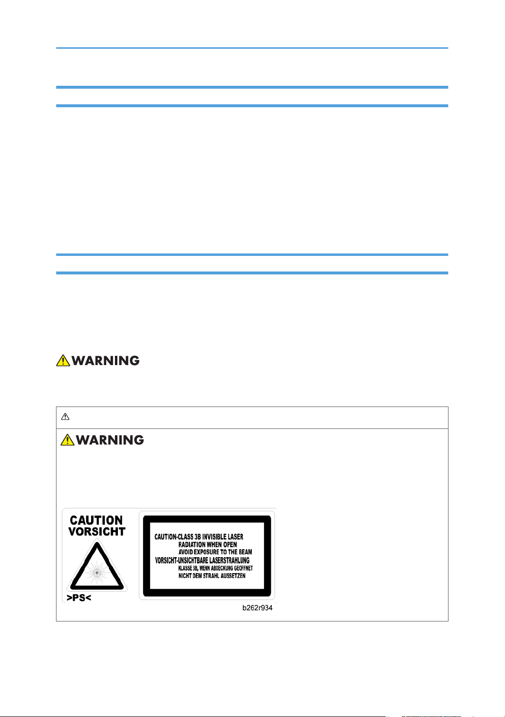
WARNING FOR LASER UNIT
• Turn off the main switch before attempting any of the procedures in the Laser Unit section. Laser
beams can seriously damage your eyes.
CAUTION MARKING:
2
Page 5
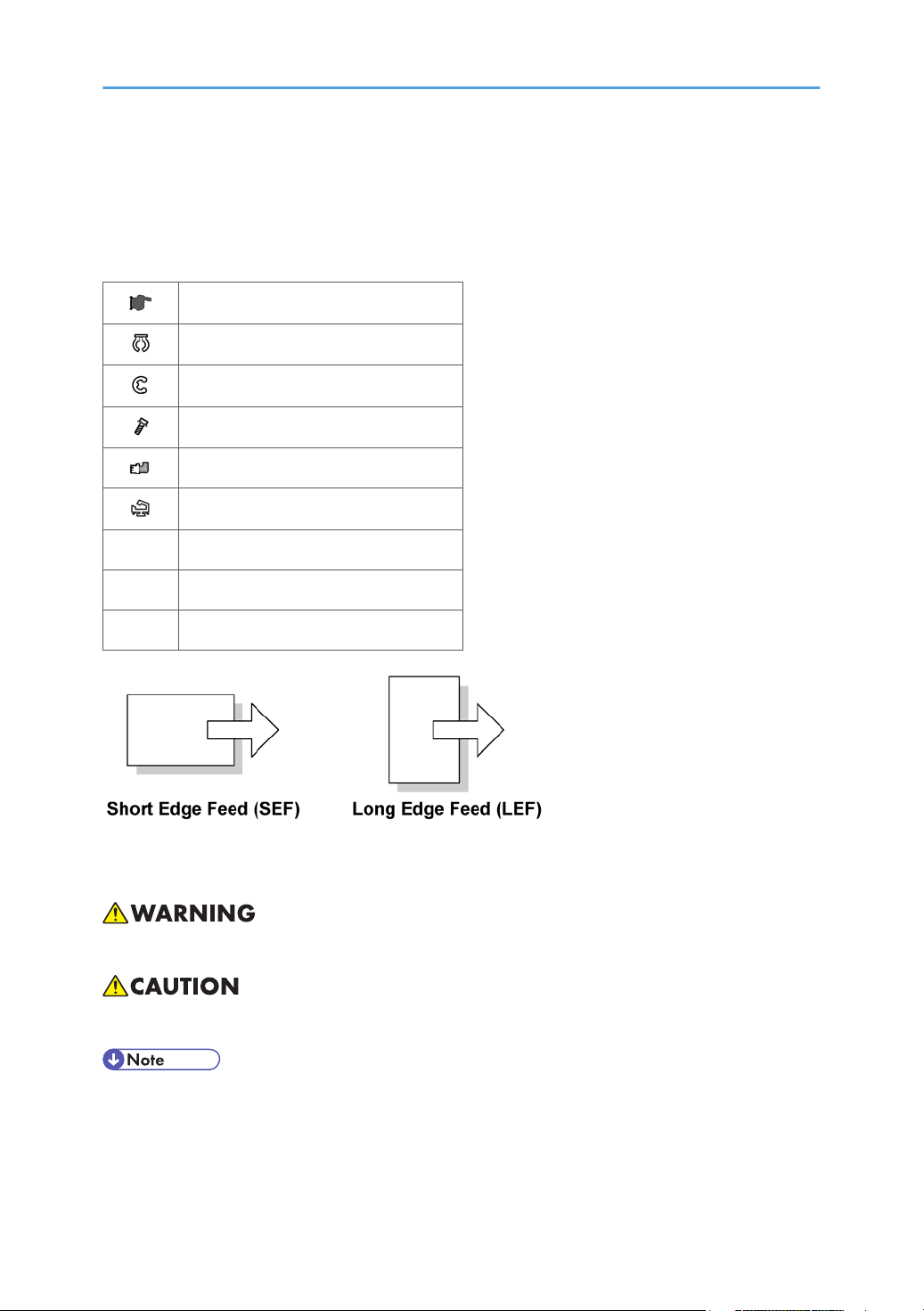
Symbols and Abbreviations
This manual uses several symbols and abbreviations. The meaning of those symbols and abbreviations is
as follows:
See or Refer to
Clip ring
E-ring
Screw
Connector
Clamp
SEF Short Edge Feed
LEF Long Edge Feed
- Core Technology manual
Cautions, Notes, etc.
The following headings provide special information:
• Failure to obey warning information could result in serious injury or death.
• Obey these guidelines to ensure safe operation and prevent minor injuries.
• This information provides tips and advice about how to best service the machine.
3
Page 6

TABLE OF CONTENTS
Important Safety Notices...................................................................................................................................1
Prevention of Physical Injury..........................................................................................................................1
Health Safety Conditions...............................................................................................................................1
Observance of Electrical Safety Standards.................................................................................................1
Lithium Batteries..............................................................................................................................................1
Safe and Ecological Disposal.......................................................................................................................2
Laser Safety.....................................................................................................................................................2
Symbols and Abbreviations
...............................................................................................................................3
1. Product Information
Specifications......................................................................................................................................................9
Machine Configuration....................................................................................................................................10
Mainframe
System Components....................................................................................................................................11
Overview..........................................................................................................................................................12
Component Layout.......................................................................................................................................12
Electrical Components.................................................................................................................................14
Paper Path....................................................................................................................................................17
Drive Layout..................................................................................................................................................18
Guidance for Those Who are Familiar with Predecessor Products..............................................................20
....................................................................................................................................................10
2. Installation
Installation Cautions.........................................................................................................................................21
Installation Requirements.................................................................................................................................22
Environment..................................................................................................................................................22
Machine Level..............................................................................................................................................22
Minimum Operational Space Requirements.............................................................................................23
Power Requirements....................................................................................................................................24
Copier...............................................................................................................................................................25
Accessory Check..........................................................................................................................................25
Optional Handset
Paper Tray Unit (D567)...................................................................................................................................34
Accessory Check..........................................................................................................................................34
Installation Procedure..................................................................................................................................34
Paper Tray Unit Heater....................................................................................................................................37
4
........................................................................................................................................32
Page 7

Accessory Check..........................................................................................................................................37
Installation Procedure..................................................................................................................................38
USB 2.0/SD Slot Type B.................................................................................................................................45
Accessory Check..........................................................................................................................................45
Installation Procedure..................................................................................................................................45
Testing the SD Card/USB Slot....................................................................................................................51
Optional Paper Tray Grip Handle..................................................................................................................53
Accessories...................................................................................................................................................53
Controller Options............................................................................................................................................55
Overview......................................................................................................................................................55
Wireless LAN (IEEE 802.11a/g) Installation...........................................................................................55
IEEE 1284 Installation.................................................................................................................................57
VM Card Type L (D467).............................................................................................................................58
Gigabit Ethernet...........................................................................................................................................59
HDD Option (D577)...................................................................................................................................61
3. Preventive Maintenance
Maintenance Tables........................................................................................................................................67
How to Clear the PM Counter.........................................................................................................................68
4. Replacement and Adjustment
Precautions........................................................................................................................................................69
General.........................................................................................................................................................69
Lithium Batteries............................................................................................................................................69
Halogen-free Cable....................................................................................................................................69
Static Electricity............................................................................................................................................69
Special Tools and Lubricants...........................................................................................................................70
Exterior Covers and Operation Panel............................................................................................................71
Rear Cover...................................................................................................................................................71
Copy Tray.....................................................................................................................................................71
Operation Panel and Upper Covers..........................................................................................................72
Right Door.....................................................................................................................................................73
Bypass Tray..................................................................................................................................................74
Platen Cover Sensor....................................................................................................................................74
Scanner Unit.....................................................................................................................................................75
5
Page 8

Exposure Glass............................................................................................................................................75
Lens Block.....................................................................................................................................................75
Exposure Lamp, Lamp Stabilizer Board.....................................................................................................76
Scanner Motor.............................................................................................................................................77
Scanner HP Sensor......................................................................................................................................79
Scanner Alignment Adjustment...................................................................................................................79
Fusing................................................................................................................................................................81
Fusing Unit....................................................................................................................................................81
Exit Sensor....................................................................................................................................................82
Hot Roller Stripper Pawls.............................................................................................................................82
Hot Roller and Fusing Lamp........................................................................................................................83
Thermoswitches and Thermistor..................................................................................................................85
Pressure Roller..............................................................................................................................................86
Checking the NIP band...............................................................................................................................87
PCU and Quenching Lamp.............................................................................................................................88
PCU...............................................................................................................................................................88
Quenching Lamp..........................................................................................................................................89
Exhaust Fan and Main Motor.........................................................................................................................90
Exhaust Fan..................................................................................................................................................90
Main Motor..................................................................................................................................................91
Paper Feed........................................................................................................................................................92
Paper Feed Roller and Friction Pad............................................................................................................92
Paper End Sensor.........................................................................................................................................92
Registration Sensor......................................................................................................................................93
Bypass Paper End Sensor...........................................................................................................................94
Bypass Feed Roller......................................................................................................................................94
Bypass Feed Clutch and Friction Pad.........................................................................................................95
Paper Feed and Registration Clutches.......................................................................................................96
Image Transfer..................................................................................................................................................98
Transfer Roller..............................................................................................................................................98
ID Sensor and Duplex Roller.......................................................................................................................99
Discharge plate.........................................................................................................................................100
BICU and Controller Board..........................................................................................................................101
6
Page 9

BICU...........................................................................................................................................................101
Controller Board........................................................................................................................................102
Other Replacements......................................................................................................................................108
Duplex Motor............................................................................................................................................108
High-Voltage Power Supply Board ........................................................................................................109
PSU.............................................................................................................................................................110
Contact-Release Solenoid........................................................................................................................111
Toner Supply Clutch..................................................................................................................................111
FCU.............................................................................................................................................................112
Laser Unit........................................................................................................................................................115
Location of the Caution Decal..................................................................................................................115
Laser Unit....................................................................................................................................................115
LD Unit and Polygon Mirror Motor..........................................................................................................116
ARDF...............................................................................................................................................................117
ARDF...........................................................................................................................................................117
DF Rear Cover...........................................................................................................................................118
Original Feed Unit.....................................................................................................................................118
Separation Roller.......................................................................................................................................119
DF Drive Board..........................................................................................................................................119
Original Set and DF Inverter Sensor........................................................................................................120
DF Registration and DF Exit Sensor..........................................................................................................121
DF Feed Motor..........................................................................................................................................122
DF Transport Motor...................................................................................................................................123
DF Feed Clutch..........................................................................................................................................124
Adjusting Copy Image Area.........................................................................................................................125
Printing........................................................................................................................................................125
Scanning....................................................................................................................................................127
DF Image Adjustment................................................................................................................................130
5. System Maintenance Reference
Service Program.............................................................................................................................................133
SP Tables....................................................................................................................................................133
Using SP and SSP Modes.........................................................................................................................133
Using SP Mode..............................................................................................................................................136
7
Page 10

NVRAM Data Upload/Download..........................................................................................................136
Firmware Update Procedure....................................................................................................................137
Test Pattern Print (SP5-902-001).............................................................................................................142
Memory Clear...........................................................................................................................................145
Machine No. Setting (SP5-811-001).....................................................................................................146
SMC Print (SP5-990)................................................................................................................................147
ID Sensor Error Analysis (SP2-221)........................................................................................................147
Fax Service Tables.........................................................................................................................................149
6. Troubleshooting
SC Tables.......................................................................................................................................................151
Summary....................................................................................................................................................151
Engine SC Code Descriptions..................................................................................................................152
GW SC Code Descriptions......................................................................................................................160
Electrical Component Defects.......................................................................................................................177
Sensor/Switch...........................................................................................................................................177
Blown Fuse Conditions..............................................................................................................................178
BICU LED Display......................................................................................................................................179
Card Save Function.......................................................................................................................................180
Overview....................................................................................................................................................180
Procedure...................................................................................................................................................180
Fax Troubleshooting Guide..........................................................................................................................183
7. Energy Saving
Energy Save...................................................................................................................................................185
Energy Saver Modes................................................................................................................................185
Energy Save Effectiveness........................................................................................................................186
Paper Save.....................................................................................................................................................188
Effectiveness of Duplex/Combine Function............................................................................................188
8
Page 11

1. Product Information
1
Specifications
See "Appendices" for the following information:
• General Specifications
Supported Paper Sizes
•
9
Page 12
1. Product Information
1
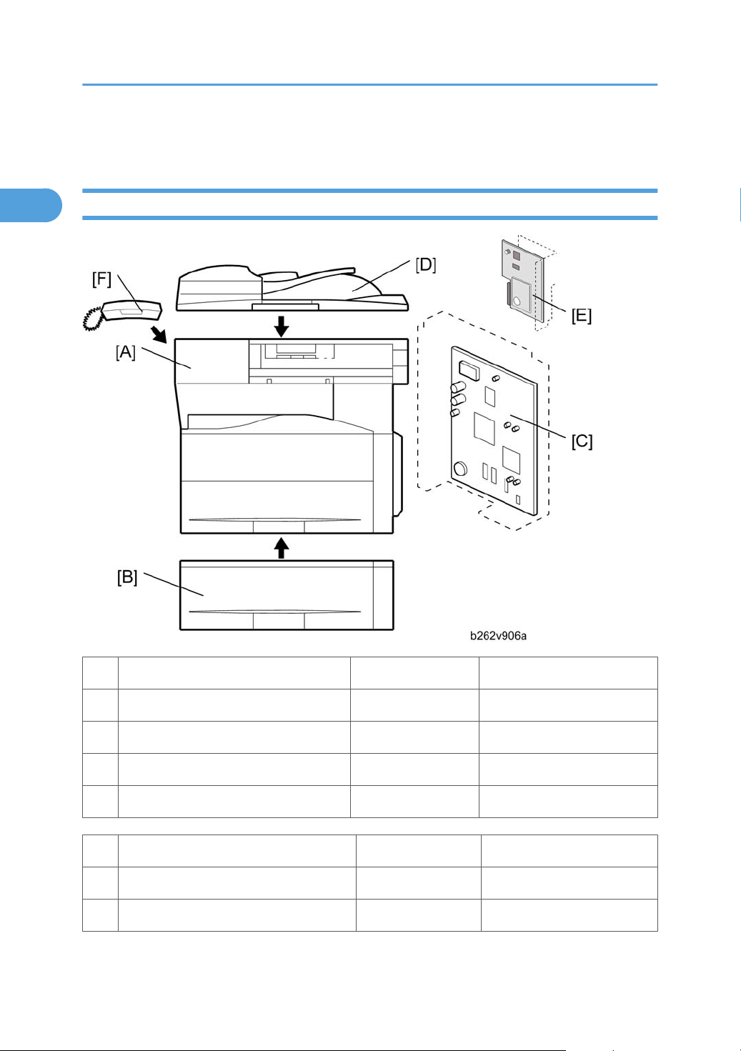
Machine Configuration
Mainframe
Standard Component Machine Code Remarks
1 Copier [A] D115/D116 -
2 GW Controller Board [C] - Standard
3 ARDF [D] - Standard
4 Fax Unit [E] - Standard
Optional Components Machine Code Remarks
5 500-sheet Paper Feed Unit [B] D567 Two can be used.
6 Handset [F] B433 NA only
10
Page 13
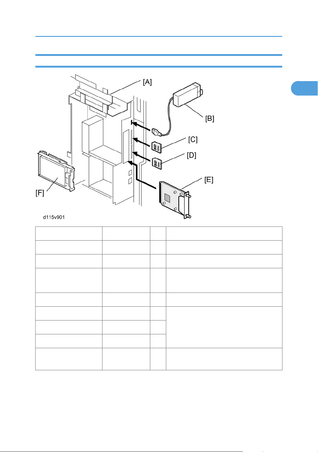
System Components
1
Machine Configuration
Item Machine Code Remarks
Controller Box - [A] Standard
USB2.0/SD Slot D467 [B] Option only for D115
Printer/Scanner unit D468 [C]
VM Card D467 [D] In SD slot 2 (lower)
IEEE 1284 B679 [E]
Gigabit Ethernet Board G874 [E]
HDD with Security Card D577 [F]
SD card for the Printer/Scanner Unit
Standard only for D115
One from the fourWireless LAN M344 [E]
Merge the Security Card into the Printer/
Scanner SD card.
11
Page 14
1. Product Information
1
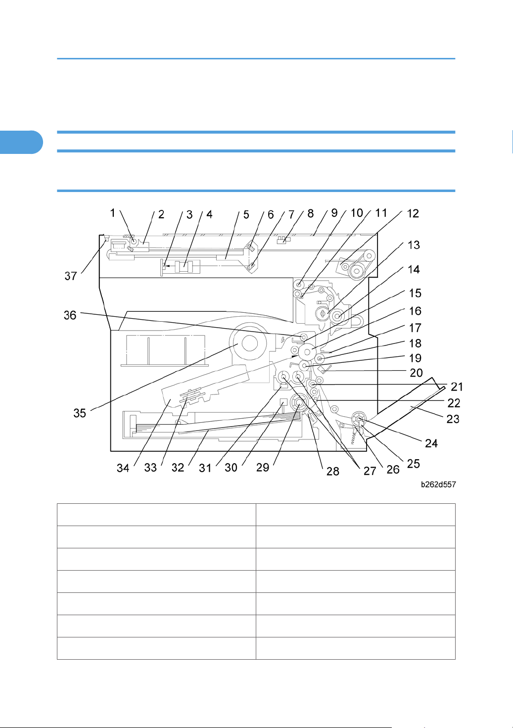
Overview
Component Layout
Mainframe
1. Exposure Lamp 20. ID (Image Density) Sensor
2. 1st Scanner 21. Registration Roller
3. CCD (on SBU) 22. Registration Sensor
4. Lens Block 23. Bypass Tray
5. 2nd Scanner 24. Bypass Paper Feed Roller
6. 2nd Mirror 25. Bypass Paper End Sensor
7. 3rd Mirror 26. Bypass Friction Pad
12
Page 15
8. Platen Cover Sensor 27. Mixing Augers
1
9. Exposure Glass 28. (Main) Friction Pad
10. Exit Roller 29. Paper Feed Roller
11. Exit Sensor 30. Paper End Sensor
12. Scanner Motor 31. TD (Toner Density) Sensor
13. Hot Roller 32. Bottom Plate
14. Pressure Roller 33. Polygon Mirror Motor
15. Cleaning Blade 34. Laser Unit
16. OPC Drum 35. Toner Supply Bottle (or THM)
17. Discharge Plate 36. Toner Collection Coil
18. Transfer Roller 37. Scanner HP Sensor
Overview
19. Development Roller
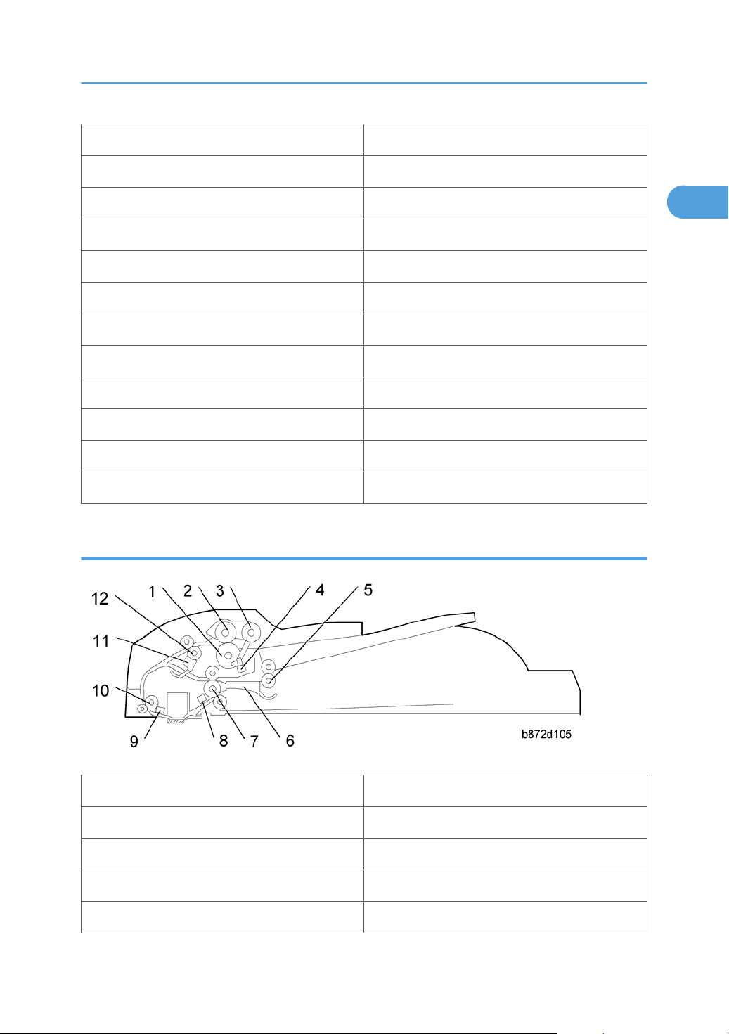
ARDF
1. Separation Roller 7. Exit Roller
2. Paper Feed Roller 8. Exit Sensor
3. Pick-up Roller 9. Registration Sensor
4. Original Set Sensor 10. Registration Roller
5. Inverter Roller 11. Inverter Sensor
13
Page 16
1. Product Information
1
6. Junction Gate 12. Transport Roller
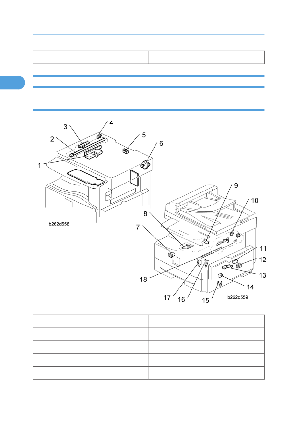
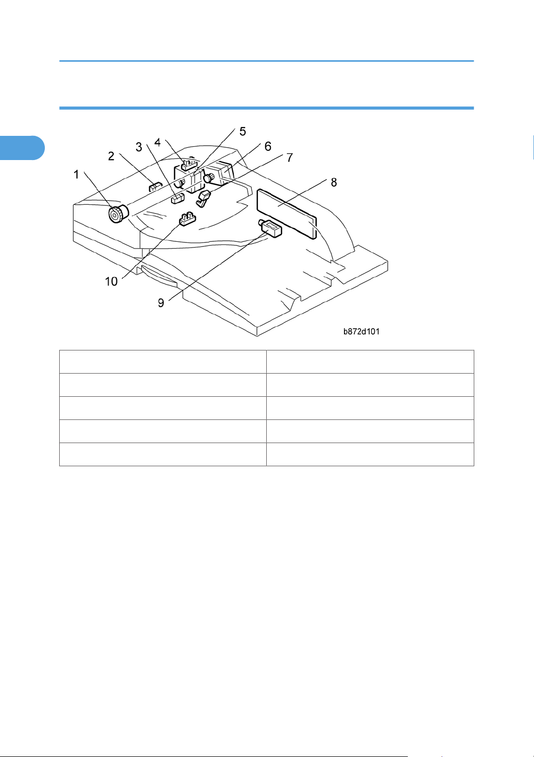
Electrical Components
Electrical Components 1
1. Lens Block 11. ID (Image Density) Sensor
2. Exposure Lamp 12. Registration Sensor
3. Lamp Stabilizer Board 13. Paper End Sensor
4. Scanner HP Sensor 14. Toner Density Sensor
5. Platen Cover Sensor 15. Bypass Paper End Sensor
14
Page 17
6. Scanner Motor 16. Right Door Safety Switch
1
7. Mechanical Counter 17. Front Door Safety Switch
8. Polygon Mirror Motor 18. Quenching Lamp
9. LD Unit 19. High-Voltage Power Supply Board
10. Exit Sensor 20. Operation Panel Board
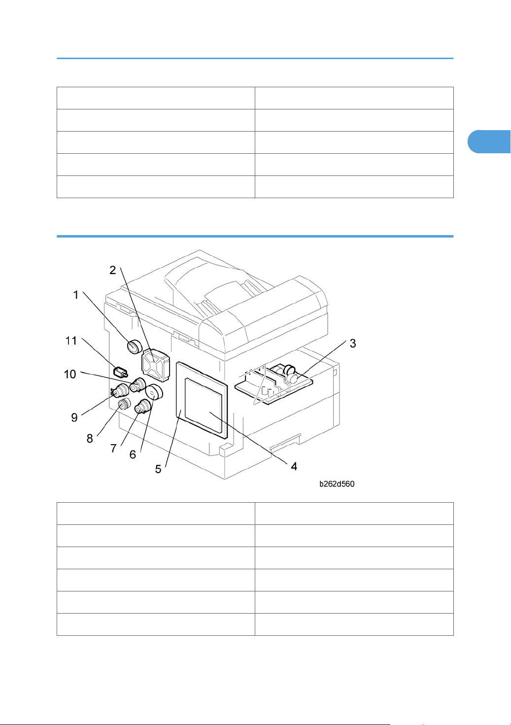
Electrical Components 2
Overview
1. Duplex Motor 7. Paper Feed Clutch
2. Exhaust Fan 8. Toner Supply Clutch
3. PSU 9. Bypass Feed Clutch
4. Controller Board (GW) 10. Registration Clutch
5. BICU 11. Fusing Solenoid
6. Main Motor
15
Page 18
1. Product Information
1
ARDF
1. DF Feed Clutch 6. DF Feed Motor
2. Registration Sensor 7. Inverter Sensor
3. Exit Sensor 8. DF Drive Board
4. Left Cover Sensor 9. Junction Gate Solenoid
5. DF Transport Motor 10. Original Set Sensor
16
Page 19
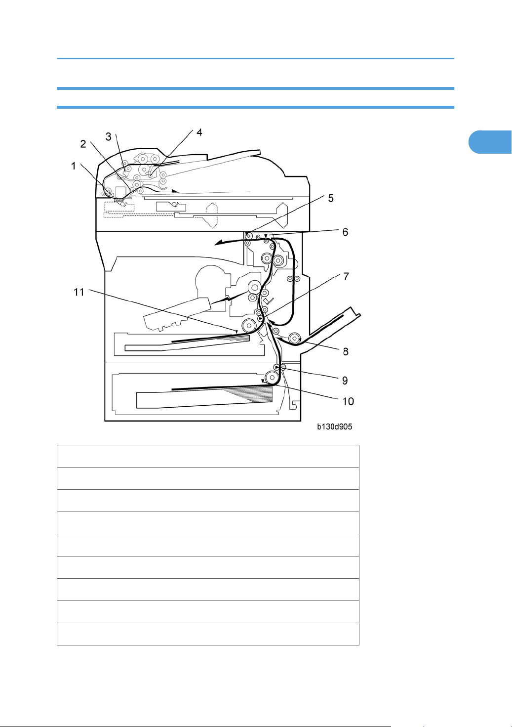
Paper Path
1
Overview
1. Original Registration Sensor (Document Feeder)
2. Exit Senor (Document Feeder)
3. Inverter Sensor (Document Feeder)
4. Original Set Sensor (Document Feeder)
5. Exit Sensor
6. Paper Path Sensor
7. Registration Sensor
8. By-pass Paper End Sensor
9. Paper Feed Sensor (Optional Tray)
17
Page 20
1. Product Information
1
10. Paper End Sensor (Optional Tray)
11. Paper End Sensor
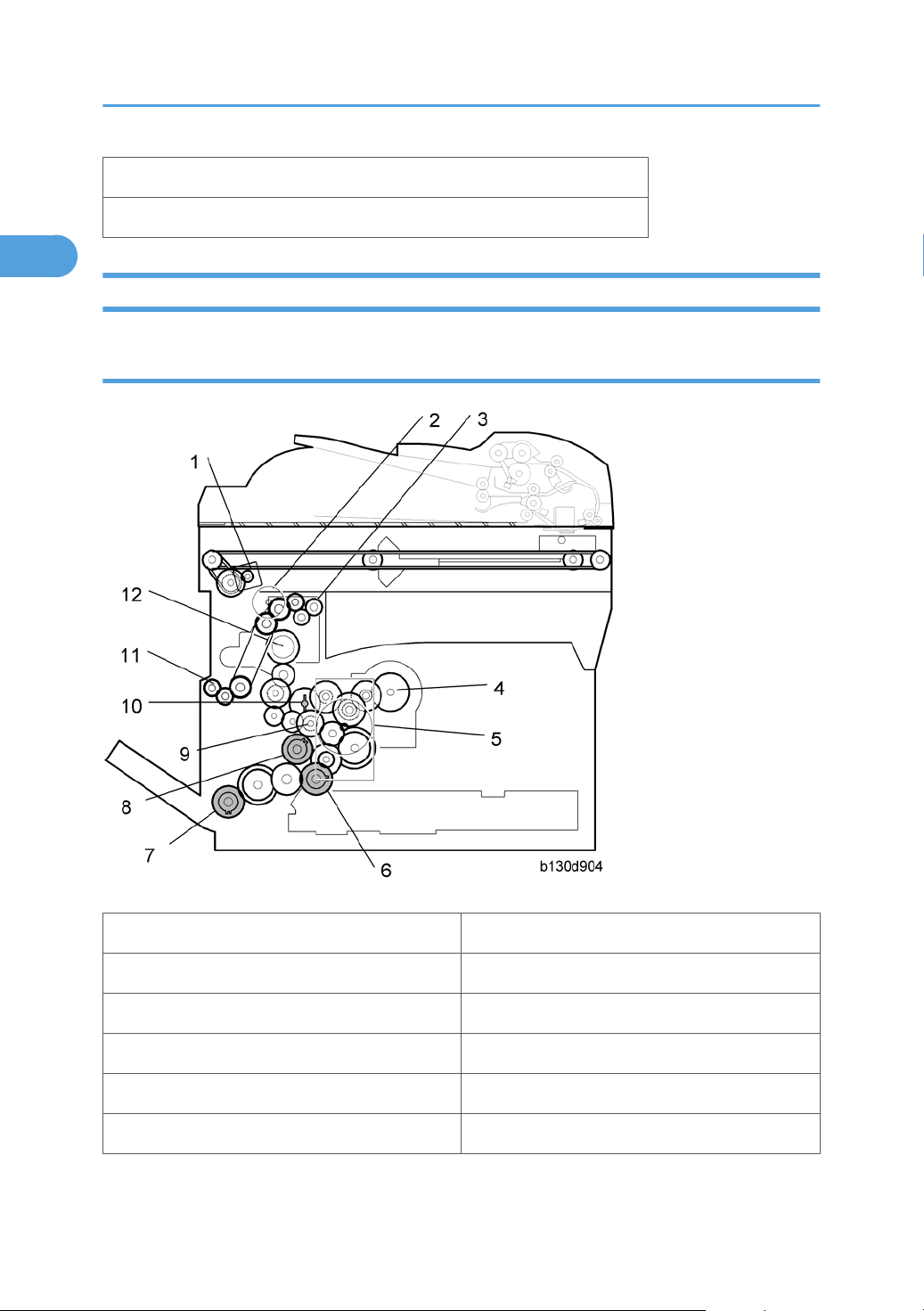
Drive Layout
Mainframe
1. Scanner Motor 7. Bypass Feed Clutch (By-pass Tray)
2. Duplex motor 8. Registration Clutch
3. Exit Roller 9. Developer Driver Gear
4. Toner Bottle Clutch 10. Drum Drive Gear
5. Main Motor 11. One-way Gear (Duplex Unit)
6. Paper Feed Clutch 12. Fusing Drive Gear
18
Page 21
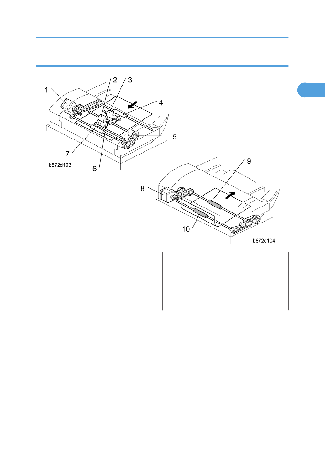
ARDF
1
Overview
1. DF Feed Motor
2. Feed Roller
3. Pick-up Roller
4. Inverter Roller
5. DF Feed Clutch
• DF Feed Motor: Drives the feed, separation, pick-up, and transport and inverter rollers.
• DF Transport Motor: Drives the registration and exit rollers.
6. Separation Roller
7. Transport Roller
8. DF Transport Motor
9. Exit Roller
10. Registration Roller
19
Page 22

1. Product Information
1
Guidance for Those Who are Familiar with Predecessor Products
The D115/D116
have experience with the predecessor line, the following information may be of help when you read this
manual.
Differences from Predecessor Products
Security Card (HDD
Encryption and Data
Overwrite Security Unit)
Copying Speed
• The following parts are unique for D115/D116. When replacing the following parts, use the parts
specified for each model. DO NOT mix up the following parts for D067/D068/D069/D072 and
D115/D116. Otherwise, both of the machine operation and output quality are not guaranteed.
BICU with Controller Unit
1.
•
If wrong part is installed, an image is not correctly copied on outputs with the DF one to one
copy.
range of machines is the successor model to the D068/D069 range of machines. If you
D115/D116 D068/D069
Standard only for D115 Option only for D069
20 cpm: Memory copy
16 cpm: ADF 1 to 1
17cpm: Memory copy
16cpm: ADF 1 to 1
2. Laser Unit (Writing Unit)
• If wrong part is installed, a copied image might be too dark or light on outputs.
3. Polygon Scanner Motor (A part of Laser Unit)
• If wrong part is installed, a copied image might be too dark or light on outputs or an SC might
be issued.
4. Model Name Plate
5. Mechanical Counter (S-C4: Assembled, S-C4.5: Service optional part)
20
Page 23

2. Installation
2
Installation Cautions
• Before installing an optional unit, do the following:
• Print out all messages stored in the memory, all user-programmed items, and a system parameter list.
• If there is a printer option on the machine, print out all data in the printer buffer.
• Turn off the main switch and disconnect the power cord, the telephone line, and the network cable.
21
Page 24
2. Installation
2
Installation Requirements
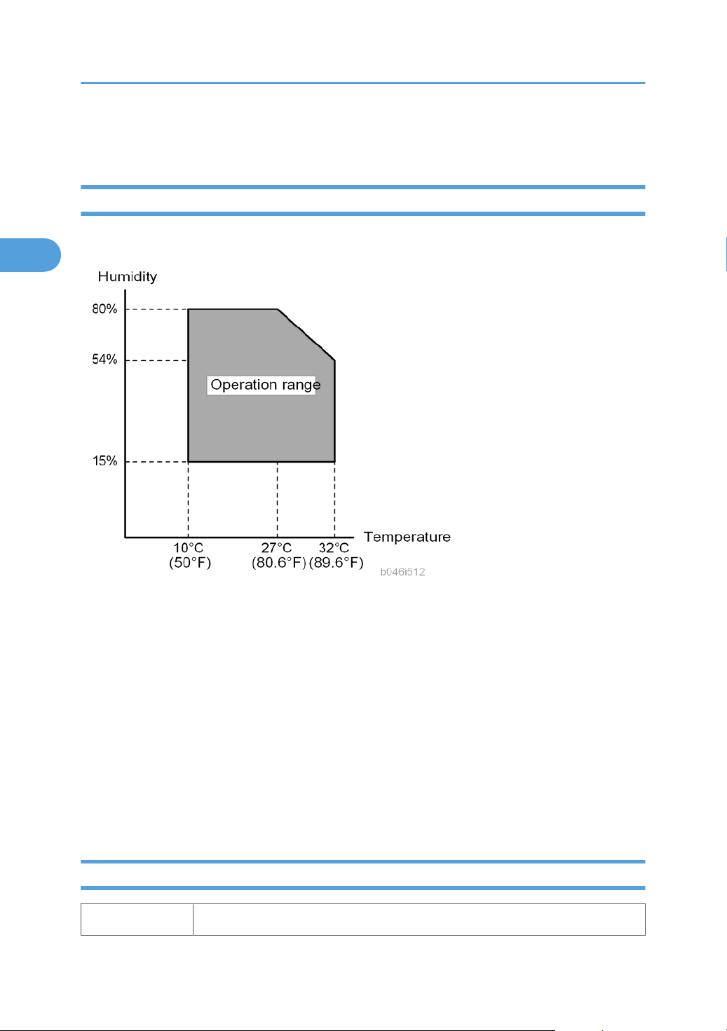
Environment
–Temperature and Humidity Chart–
• Temperature Range: 10°C to 32°C (50°F to 89.6°F)
• Humidity Range: 15% to 80% RH
•
• Ventilation: Room air should turn over at least 3 times/hr/person
• Ambient Dust: Less than 0.1 mg/m
• Do not install the machine where it will be exposed to direct sunlight or to direct airflow (from a fan,
• Do not install the machine where it will be exposed to corrosive gas.
• Place the machine on a firm and level base.
• Do not install the machine where it may be subjected to strong vibration.
Machine Level
Front to back: Within 5 mm (0.2") of level
22
Ambient Illumination: Less than 1,500 lux (Do not expose to direct sunlight.)
3
air conditioner, air cleaner, etc.).
Page 25
Right to left: Within 5 mm (0.2") of level
2
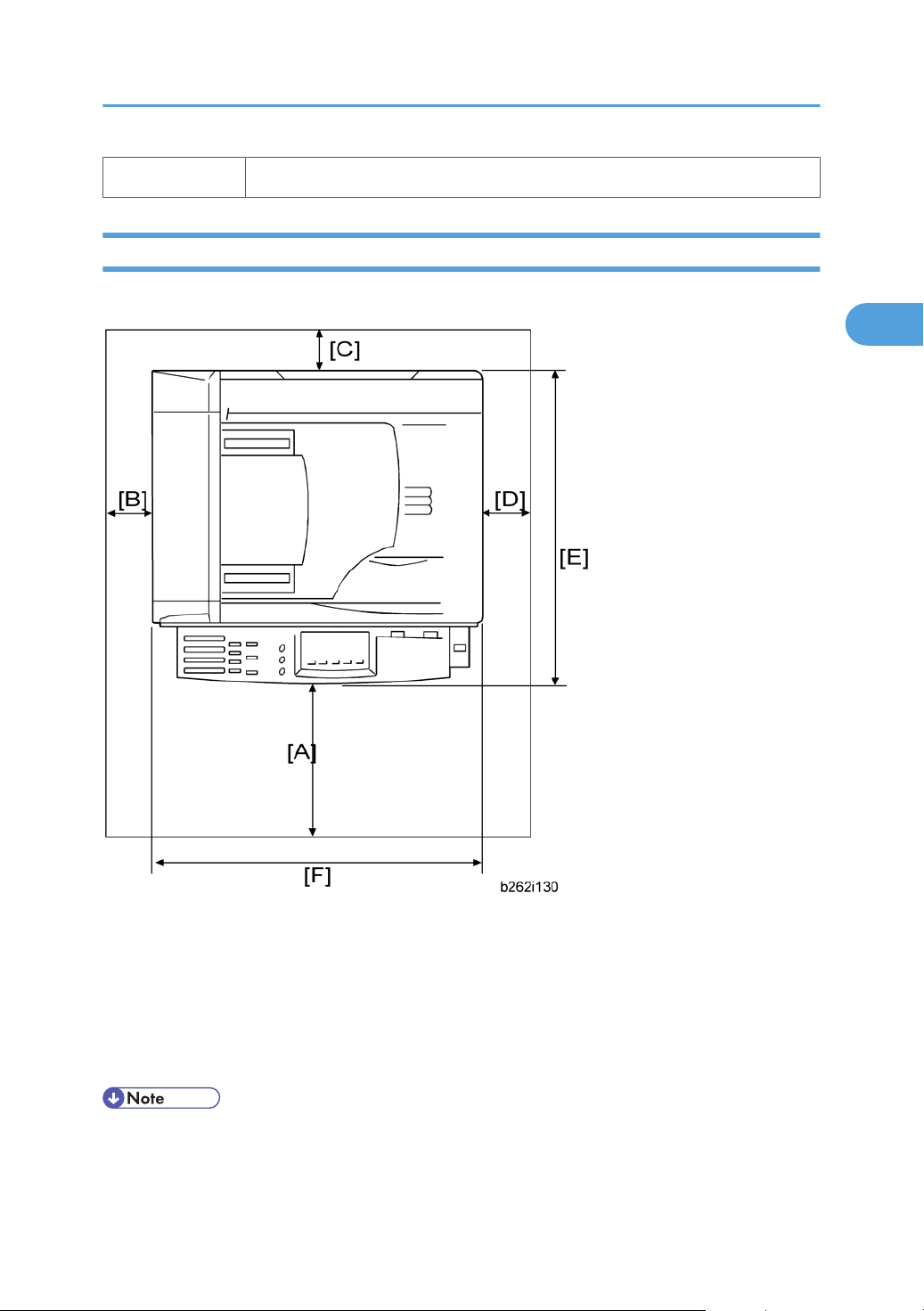
Minimum Operational Space Requirements
Place the machine near the power source, providing clearance as shown.
Installation Requirements
A: Front – 750 mm (29.6")
B: Left – 100 mm (3.9")
C: Rear – 100 mm (3.9")
D: Right – 100 mm (3.9")
E: Depth – 450 mm (17.7")
F: Width – 485 mm (19.1")
• The 750-mm front space indicated above is sufficient to allow the paper tray to be pulled out.
Additional space is required to allow an operator to stand at the front of the machine.
23
Page 26

2. Installation
2
• Actual minimum space requirement for left, rear, and right sides is 10mm (0.4") each, but note that
this will not allow room for opening of the bypass tray, right door or ARDF unit.
Power Requirements
• Make sure that the wall outlet is near the machine and easily accessible. After completing installation,
make sure the plug fits firmly into the outlet.
Avoid multiple connections to the same power outlet.
•
• Be sure to ground the machine.
Input voltage:
North America:
Europe: 220 – 240 V, 50/60 Hz, 4 A
Image quality guaranteed at rated voltage ± 10%.
Operation guaranteed at rated voltage ± 15%.
110 – 120 V, 60 Hz, 8 A
24
Page 27

Copier
2
Accessory Check
Printer/Scanner and Fax Model (D115)/ Fax Model (D116)
Description Q’ty
NECR (-17) 1
EU Safety Sheet (-27) 1
Paper Size Decal (-17, -27, -29) 1
Operating Instructions – Book (-17, -29) 1 set
Operating Instructions – CD ROM (-17, -29) 1 set
Copier
Handset Bracket (-17) 1
Screw for Handset Bracket (-17) 2
Modular Cable (-17) 1
Connecter Cover for TEL (-17) 1
Ferrite Core for TEL Line 1
Ferrite Core (-17, -27, -29) 1
EMC Caution Sheet (-27) 1
EULA Sheet (-17, -27, -29) 1
Caution Decal (-17, -27, -29) 1
Installation Procedure
• Make sure that the copier remains unplugged during installation.
25
Page 28
2. Installation
2
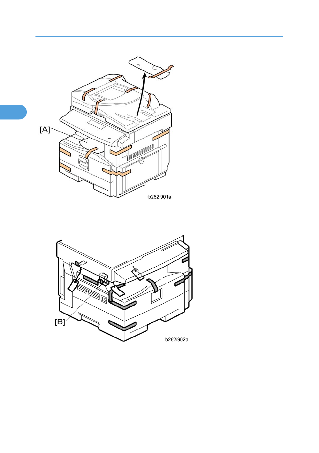
1. Remove the all strips of tape.
2. Remove the bag [A], SMC and A3 sheet of paper on the exposure glass.
3. Remove the spacing wedge [B].
26
Page 29
Copier
2
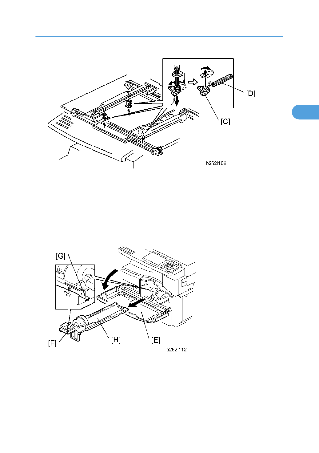
4. Remove the three scanner lock pins. (A tag is hanging from each pin.) To remove: Grasp the base of
the pin [C], turn the pin 90 degrees, and pull it down and out.
5.
Remove the tags from the pins.
6. Break each pin off the base [C].
7. Discard the pin part [D].
8. Set each base [C] back into its original hole, turning it 90° to lock it into place. (Be sure to do this for
all three pins.)
9. Open the front door [E].
10. Lift lever
out of the machine.)
11. Take a new bottle of toner, and shake it several times.
[F], press in on latch [G] and pull the bottle holder [H] out. (You do not need to pull it completely
27
Page 30
2. Installation
2
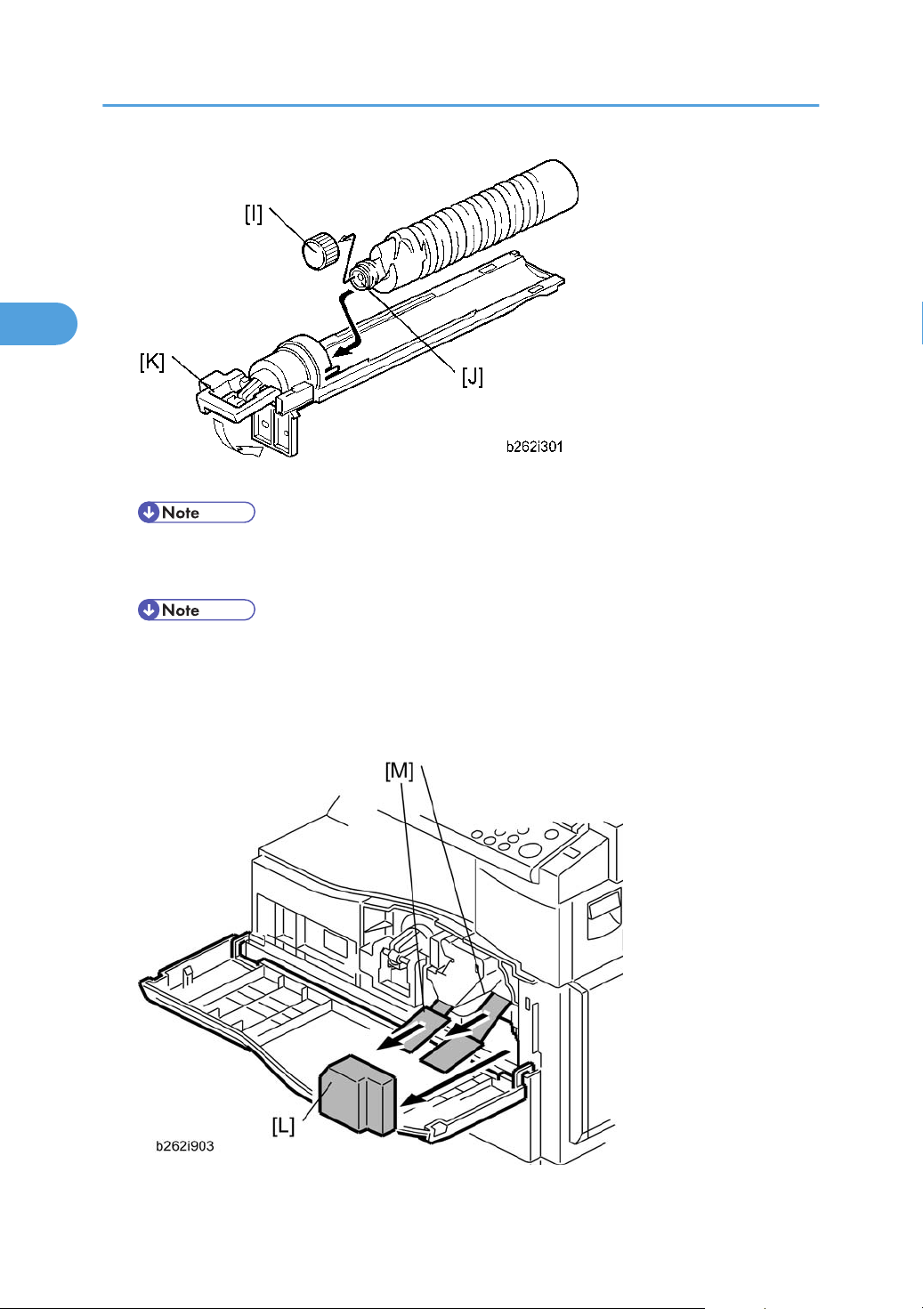
12. Remove the outer cap [I].
• Do not remove the inner cap [J].
13. Load the bottle on the holder.
• Do not forcefully turn the toner bottle on the holder. After you turn on the main power switch, the
copier sets the bottle in place.
14.
Push the bottle holder back into the machine.
15. Press the latch [K] down to lock the holder.
16. Remove the padding [L].
28
Page 31

17. Pull each tabbed strip [M] out of the PCU with one hand, supporting the PCU with the other.
2
• Do not pull both strips at the same time, as this could damage the PCU.
18. Close the front door.
Copier
19. Pull out the paper tray, and remove the tape securing the end fence in the compartment.
20. Push the bottom plate down, and then load the paper.
Adjust the side fences. If you load paper shorter than A4, set the end fence in the correct position.
21.
22. Push the tray back into the copier.
23. Attach the appropriate Brand Decal to the center [N] of the front door if necessary.
24. Attach the appropriate tray number decal and paper-size decal to the paper tray [O].
Install optional units (if any).
25.
29
Page 32

2. Installation
2
26. Attach the ferrite core [P] to the network cable when connecting the cable.
27. Attach the ferrite core to the telephone line in the same manner as step 26.
28.
Connect the telephone line to the "LINE" jack.
• The end of the ferrite core must be about 10 cm (4") from the end of the cable.
29. Plug in the machine and turn on the main power switch.
Select the language used in the operation panel as necessary (
30.
> Language).
Interface settings
For D115:
1. Start the SP mode.
Select SP5-985-001 (NIC setting) and change the setting value to "1" (ON).
2.
3. Select SP5-985-002 (USB setting) and change the setting value to "1" (ON).
4. Turn the main switch off and on.
For D116:
1. Start the SP mode.
2. Select SP5-985-001 (NIC setting) and change the setting value to "0" (OFF).
3. Select SP5-985-002 (USB setting) and change the setting value to "0" (OFF).
4. Turn the main switch off and on.
30
Page 33

Copier settings
2
1. Start the SP mode.
2. Select SP5-801-001 and execute the initialization.
3. Exit the SP mode, and then start the UP mode.
4. Select the "@Remote Service" ("User Tool" > "System Settings > Administrator Tools" > "Extended
Security" > @Remote Service") and select "Prohibit".
5. Exit the UP mode, and then start the SP mode.
6. Select SP5-870-003 and execute initialization for @Remote.
7. Select SP5-907-001 and specify the "Plug & Play".
8. Select SP5-870-001 and execute writing certification for @Remote S.
9. Select SP5-302-002 and specify the time zone.
10. Select SP5-307-001, 003, and 004 and specify the daylight-saving-time settings.
11. Exit the SP mode and turn the main switch off and on.
12. Start the UP mode.
Copier
13. Specify the date and time with "Set Date" or "Set Time" (User Tool" > "System Settings" > "Set Date"
or "Set Time").
14. Turn the main switch off and on.
15. Check the operations.
16. Make a full size copy, and check if the side-to-side and leading edge registrations are correct. If they
are not, adjust the registrations.
Fax Settings
Initializing the Fax unit
When you press the Fax key for the first time after installation, the error "SRAM problem occurred / SRAM
was formatted" will show on the LCD for initializing the program of the fax unit. Turn the main power switch
off/on to clear the error display.
• If another error occurs after initialization, this can be a functional problem.
1. Select fax SP1-101-016 and specify the country code.
Select fax SP3-101-001 and specify the service station.
2.
31
Page 34

2. Installation
2
Optional Handset
Accessory Check
Check that you have the components and accessories.
No. Description Q’ty
1 Handset 1
2 Handset cradle 1
3 Screws 2
4 Handset manual 1
• The handset bracket is not included in the optional handset kit. The bracket is provided as an accessory
of the copier.
32
Page 35

Installation Procedure
2
1. Attach the handset bracket [A] ( x 2)
2. Remove the label from the handset cradle [B].
Attach the cradle [B] to the handset bracket (
3.
4. Attach the cradle to the bracket ( x 2).
5. Reattach the label.
Copier
x 2).
• The bracket is an accessory of the copier.
6. Set the handset on the cradle.
7. Connect the handset cable to the "TEL" jack and set the telephone cable [A] as shown above.
33
Page 36

2. Installation
2
Paper Tray Unit (D567)
Accessory Check
Confirm that you have these accessories.
Description Q’ty
1. Paper-size decals 1 sheet
2. Installation Procedure (for service technicians) 1
3. Installation Procedure (for users) 1
4. Tapping Screw: M3x10 1
5. EMC Caution Sheet 1
Installation Procedure
• Unplug the main machine's power cord before starting the following procedure.
1. Remove the tape at [A], and the tape and cardboard at [B].
2. Pull the
paper tray part way out of the unit, remove the tape and cardboard at [C], and push the tray
back in.
34
Page 37

Paper Tray Unit (D567)
2
3. Set the machine on the paper tray unit.
• When installing a second paper tray unit, place on the first paper tray unit before placing the
copier onto the pair pf paper tray units
4. Remove the paper(s) tray from the paper tray unit(s).
5.
Load paper into the paper tray(s). Adjust the side and end fences as necessary. If loading 81/2"x
14" paper, remove the end fence and set it into the special compartment.
6. Set the paper tray(s) back into the paper tray unit(s).
35
Page 38

2. Installation
2
7. Stick on the appropriate tray-number decal(s) and paper-size decal(s), at the locations indicated in
the illustration.
36
Page 39

Paper Tray Unit Heater
2
The paper tray unit heater is installed only for the first paper tray unit.
Accessory Check
Confirm that you have the accessories listed below.
Description Q’ty
1. Grounding wire 1
2. Relay harness 1
3. Clamps 2
4. Ferrite core 1
5. Heater fastening screws 2
Paper Tray Unit Heater
6. PTU fastening screws 3
7. Grounding screw 1
8. Decal for copier 1
9. Decal for paper tray unit 1
10. Tie wrap 1
37
Page 40

2. Installation
2
Installation Procedure
• Unplug the main machine's power cord before starting the following procedure.
1. Remove the paper tray unit from the copier if it is already installed.
2.
Remove the paper trays from the copier and from the paper tray unit.
38
Page 41

Paper Tray Unit Heater
2
3. Remove the ground screw [1] at the rear of the paper tray unit.
4. Fasten the heater [2] and the supplied ground wire [3] to the paper tray unit ( x 3). Note that [1]
is the ground screw you removed in the previous step and [4] and [5] are the two supplied heater
fastening screws.
• Be sure to position the ground wire [3] and heater harness [6] so that they are out of the way of
the copier when you set it on the paper tray unit.
5. Set the copier on the paper tray unit.
6. Screw the paper tray unit into place using three supplied PTU fastening screws.
39
Page 42

2. Installation
2
7. Open the front door and remove the copy tray [7] ( ×1).
8. Close the front door.
1. Open the right cover
2. Remove the interface cover [8] ( x 1).
3. Remove the rear cover [9] ( x 5).
40
Page 43

4. Remove the upper left cover [10].
2
Paper Tray Unit Heater
5. Remove the controller box [11] ( x 1, x 6).
6. Remove the support bracket [12] ( x 3).
41
Page 44

2. Installation
2
7. Pass the heater harness through the hole [15] at the rear of the copier.
8. Pass relay harness [16] through the opening [17] (at the rear of the PSU) and through the other
opening [15].
Connect the relay harness to the heater's harness [18].
9.
10. Pull the relay harness back into the copier.
42
Page 45

Paper Tray Unit Heater
2
11. Attach the ferrite core [19] over the relay harness.
12. Push the ferrite core back so that it is over the heater's harness.
13. Wrap the heater's harness once around the ferrite core [20].
14. Locate the ferrite core at the rear [24] of the copier behind the rear clamps.
15. Secure the ferrite core with the supplied tie wrap [21].
16. Clip off the excess length of the tie wrap.
17. Connect the relay harness connector [22] to the large connector at the front center of the PSU.
18. Screw the ground wire [23] to the PSU bracket with the included grounding screw.
19. Attach the clamps [24] to the PSU bracket.
20. Attach the heater harness though the clamps.
21. Position the harness so that the front clamp is between the two bindings [25] on the harness.
22. Fasten the clamps.
23. Pull the excess length of the heater's harness out the opening at the rear.
• Be sure that the harness passes on the side of the grounding plate at the bottom of the opening.
(The front of the grounding plate must remain clear.)
24.
Arrange the excess harness length so that it sits beneath the FCU cover plate.
25. Attach the caution decals to the locations shown in the illustration.
43
Page 46

2. Installation
2
26. Reassemble the copier.
27. Plug in the power cord, and check the operation.
44
Page 47

USB 2.0/SD Slot Type B
2
This procedure explains how to install the USB 2.0/SD Slot for the SPF model (D115).
Accessory Check
Check the quantity and condition of the accessories against the following list.
No. Description Q’ty
1 USB2.0/SD Slot 1
2 Ground Plate 1
3 USB Cable 1
4 Screw: M3 x 6 blue 1
5 Screw: M3 x 8 2
USB 2.0/SD Slot Type B
6 Screw: 1
7 Clamp 1
8 Decal 1
Installation Procedure
1. Remove the USB connect cover [A].
45
Page 48

2. Installation
2
2. Remove the interface cover [A].
3. Open the right door [A].
4. Rear cover [B] ( x 5)
5. Remove the upper left cover [A] as shown above.
46
Page 49

USB 2.0/SD Slot Type B
2
6. Make three holes in the upper left cover with a screwdriver as shown above.
• Smooth the three holes in the upper left cover.
7. Attach the ground plate [A].
8. Secure the USB2.0/SD Slot [B] with the upper left cover as shown above ( x 1: M3 x 6 blue,
x 2: M3 x 8).
47
Page 50

2. Installation
2
9. Make a clamp hole the upper left cover with a screwdriver as shown above.
• Smooth the hole in the upper left cover.
10. Attach the upper left cover [A] to the mainframe.
11. Attach the rear cover.
12. Attach the cable clamp [A] to the upper left cover ( x 1) as shown above.
48
Page 51

13. Connect the USB cable [A] to USB-A.
2
14. Attach the interface cover.
Plug in and turn on the main machine.
15.
16. Enter the SP mode, and then change the setting of SP1013-001 from “0” to “1”.
USB 2.0/SD Slot Type B
17. Attach the decal [A] to the USB2.0/SD Slot as shown above.
When Installing the Handset
1. Do steps 1 to 8 in “installation procedure”.
49
Page 52

2. Installation
2
2. Make two holes the upper left cover with a screwdriver as shown above.
• Smooth the holes in the upper left cover.
3. Attach the handset bracket [A] ( x 2)
4. Attach the cradle [B] to the handset bracket ( x 2)
50
Page 53

USB 2.0/SD Slot Type B
2
5. Set the handset on the handset bracket.
6. Connect the handset cable to the “TEL” jack and set the telephone cable [A] as shown above.
Do steps 13 to 17 in “installation procedure”.
7.
Testing the SD Card/USB Slot
1. Insert an SD card or USB memory device in the slot.
You can connect only one removable memory device at a time.
2. Close the media slot cover.
you leave the cover open, static electricity conducted through an inserted SD card could cause the
If
machine to malfunction.
3. Make sure that no previous settings remain.
If a previous setting remains, press the [Clear Modes] key.
4. Place an original on the exposure glass.
5. Press [Store File].
6. Press [Store to Memory Device].
7. Press [OK].
8. Press the [Start] key.
When writing is complete, a confirmation message appears.
9. Press [Exit].
51
Page 54

2. Installation
2
10. Remove the memory device from the media slot.
Do not remove the memory device while writing is in process.
52
Page 55

Optional Paper Tray Grip Handle
2
Optional Paper Tray Grip Handle
The following procedure is for the paper tray for the main copier or optional paper tray unit.
Accessories
Check the accessories and their quantities against the table below.
No. Description Q’ty
1 Grip Handle 1
2 Screw (M3 x 10) 2
53
Page 56

2. Installation
2
Installation Procedure
1. Remove the paper tray [A] from the main copier.
54
2. Turn the paper tray over to the opposite side.
3. Lower the paper tray grip handle [B] into the paper tray slot as shown, with the arrow in the above
illustration.
4.
Attach the grip handle to the paper tray (
• When attaching auxiliary handle (two screws attached from bottom), hold handle against front
of paper drawer (as screws are tightened) to ensure there is ensure the smallest gap between
back of handle and front of paper drawer.
Put the paper tray back into the machine.
5.
x 2).
Page 57

Controller Options
2
Controller Options
Overview
This machine has I/F card slots and SD card slots for optional I/F connections and applications.
I/F Card Slot
• Slot [A]
or Gigabit Ethernet).
SD Card Slot
• Slot [1] is used for options provided on SD cards. The application SD card (Printer/Scanner or Security
Card) should be installed in Slot 1. If more than one application is to be used, move the applications
to the same SD card with SP5873.
• Slot [2] is used for options provided on SD cards and servicing. The VM card must be installed in Slot
2.
is used for one of the optional I/F connections: (IEEE1284, IEEE802.11a/g (Wireless LAN)
Wireless LAN (IEEE 802.11a/g) Installation
• Unplug the machine power cord before starting the following procedure.
55
Page 58

2. Installation
2
Accessories
Check the accessories and their quantities against the table below.
No. Description Q’ty
1 Wireless Adapter 1
2 Wireless LAN Card 1
3 LAN Card Cover 4
4 Caution Sheet 1
5 Label 1
Installation Procedure
1. Remove the interface cover [A] ( x 2).
2. Install the Wireless adaptor into I/F slot [B] ( x 2).
3. Install the Wireless LAN card in the wireless adaptor.
4.
Attach the antenna cap to the wireless LAN card.
5. Turn on the main power switch.
6. Print out the configuration page (User Tools/Counter > Printer Features > List/Test Print), and then
check that this device is detected.
If reception is poor, you may need to move the machine:
• Make sure that the machine is not located near an appliance or any type of equipment that could
generate a strong magnetic field.
56
Page 59

Controller Options
2
• Position the machine as close as possible to the access point.
SP Mode Settings for IEEE 802.11a/g Wireless LAN
The following SP commands can be set for IEEE 802.11a/g
SP No. Name Function
5840 004 SSID Used to confirm the current SSID setting.
5840 006 Channel MAX Sets the maximum range of the channel settings for the country.
5840 007 Channel MIN
5840 011 WEP Key Select Used to select the WEP key (Default: 00).
5840 018 SSID Check Used to check the SSID.
5840 020 WEP Mode
Sets the minimum range of the channel settings allowed for your
country.
Used to display the maximum length of the string that can be
used for the WEP Key entry.
IEEE 1284 Installation
• Unplug the machine power cord before starting the following procedure.
Accessories
Check the accessories and their quantities against the table below.
No. Description Q’ty
1 IEEE1284 Interface Ass’y 1
2 UL Sheet 1
3 Caution Sheet 1
57
Page 60

2. Installation
2
Installation Procedure
1. Remove the interface cover [A] ( x 2).
2. Install the IEEE 1284 board into I/F slot [B] ( x 2).
3. Turn on the main power switch.
Print out the configuration page (User Tools/Counter > Printer Features > List/Test Print), and then
4.
check that this device is detected.
VM Card Type L (D467)
Accessories
Check the accessories and their quantities against the table below.Accessories
No. Description Q’ty
1 VM SD Card 1
2 Decal 1
58
Page 61

Installation
2
1. Remove the interface cover [A] ( x 1).
Controller Options
2. Switch the machine off.
3. Insert the SD card [A] into SD Slot 2 (lower).
• This SD card must be inserted into Slot 2, the lower slot.
Gigabit Ethernet
• Unplug the main machine power cord before you do the following procedure.
59
Page 62

2. Installation
2
1. Remove the I/F-slot cover [A] ( x 2).
2. Install the Gigabit Ethernet board (Knob-screw x 2) into the I/F-slot [B].
3. Attach one ferrite core [A] to the Ethernet interface cable, and then attach the other ferrite core [B]
about 10cm from the end of the Ethernet interface cable.
4. Connect the Ethernet interface cable to the Gigabit Ethernet port.
Make sure that the machine can recognize this option (see ‘Check All Connections’ at the end of this
section).
60
Page 63

HDD Option (D577)
2
Component Check
No. Description Q’ty
1 HDD Unit 1
2 Screw 3
3 Security Card 1
- EMC Caution Sheet 1
Controller Options
61
Page 64

2. Installation
2
Installation Procedure
1. Open the right door [A].
2. Interface cover [B] ( x 1)
3. Rear cover [C] ( x 5)
62
Page 65

4. Controller box cover [A] ( x 13)
2
5. Remove the screw [A] on the controller board.
Controller Options
6. Install the HDD unit [B] in the controller board ( x 3).
• The screw [A] is used in this step.
7. Reinstall the controller box cover and rear cover in the machine.
After Installing the HDD
1. Do SP5832-001 to format the hard disk.
2. Do SP5853-001
3. Do SP5846-040 to copy the address book to the hard disk from the controller board.
4. Do SP5846-041 to let the user get access to the address book.
5. Turn the main power switch off/on.
to copy the preset stamp data from the firmware to the hard disk.
Installing the Security Card
1. Insert the Security Card in the SD slot.
• For D115, use slot 2 (lower) and merge the Security Card into the Printer/Scanner card with
SP5-873-001. Remove the Security Card from the SD slot 2 after moving the security
applications and keep the Security Card at a safe location.
• For D116, use slot 1 (upper).
2. Enter the SP mode.
63
Page 66

2. Installation
2
3. Input a machine serial number with SP 5811-001.
4. Go into the SP mode and push “EXECUTE” with SP5-878-001.
5. Select SP5878-002, and then press "Execute" on the LCD.
6. Exit the SP mode after "Completed" is displayed on the LCD.
Activating the Security Applications
1. Make sure that the following settings are not at their factory default values:
• Supervisor login password
• Administrator login name
• Administrator login password
If any of these settings is at a factory default value, tell the customer these settings must be changed
before you do the installation procedure.
2. Make sure that “Admin. Authentication” is ON.
[System Settings] – [Administrator Tools] – [Administrator Authentication Management] - [Admin.
Authentication]
If this setting is OFF, tell the customer this setting must be ON before you do the installation procedure.
3. Make sure that “Administrator Tools” is enabled (selected).
[System Settings] – [Administrator Tools] – [Administrator Authentication Management] - [Available
Settings]
If this setting is disabled (not selected), tell the customer this setting must be enabled (selected) before
you do the installation procedure.
4. Refer to the Security Reference for details about activating the security applications (HDD Encryption
Unit and DataOverwriteSecurity).
HDD Encryption Recovery from a Device Problem
The flowchart below shows the recovery possibility of the HDD encryption if one of devices related with
the HDD encryption is defective.
64
Page 67

Controller Options
2
Restoring the Encryption key
When replacing the controller board for a model in which the HDD encryption unit has been installed,
updating the encryption key is required.
1. Prepare an SD card which is initialized.
2.
Make the "restore_key" folder in the SD card.
3. Make an "nvram_key.txt" file in the "restore_key" folder in the SD card.
4. Ask an administrator to input the encryption key (this has been printed out earlier by the user) into the
"nvram_key.txt" file.
5. Remove only the HDD unit (
6. Turn on the main power switch.
7.
Confirm that the prompt on the LCD tells you to install the SD card (storing the encryption key) in the
machine.
8. Turn off the main power switch.
9. Insert the SD card that contains the encryption key into slot 1.
10. Turn on the main power switch, and the machine automatically restores the encryption key in the flash
memory on the controller board.
11. Turn off the main power switch after the machine has returned to normal status.
12. Remove the SD card from slot 1.
HDD).
13. Reinstall the HDD unit.
65
Page 68

2. Installation
2
Clearing the NVRAM
When replacing the controller board for a model in which the HDD encryption unit has been installed and
a customer has lost the encryption key, clearing the NVRAM is required to recover the HDD encryption
unit.
1. Prepare an SD card which is initialized.
2. Make the "restore_key" folder in the SD card.
3. Make an "nvram_key.txt" file in the "restore_key" folder in the SD card.
4. Input "nvclear" into the "nvram_key.txt" file.
5. Turn on the main power switch.
6. Confirm that the prompt on the LCD tells you to install the SD card (storing the encryption key) in the
machine.
7. Turn off the main power switch.
8. Insert the SD card that contains "nvclear" into slot 1.
9. Turn on the main power switch, and the machine automatically restores the encryption key in the flash
memory on the controller board.
10. Turn off the main power switch after the machine has returned to normal status.
11. Remove the SD card from slot 1.
12. Turn on the main power switch.
13. Initialize the NVRAM (SP5801-001) and HDD unit (SP5832-001) with SP mode.
14. The user must enable the HDD encryption unit with a user tool.
66
Page 69

3. Preventive Maintenance
3
Maintenance Tables
See "Appendices" for the following information:
• PM tables
67
Page 70

3. Preventive Maintenance
3
How to Clear the PM Counter
Reset the PM counter after your maintenance work.
1. Activate the SP mode.
2.
Select SP7-804-001.
Press the EXECUTE key [A]. The message "Completed" is displayed when the program ends normally.
3.
An error message is displayed if the program ends abnormally.
4. Press the Escape key [B] to end the program.
68
Page 71

4. Replacement and Adjustment
4
Precautions
General
• Turn off the main power switch and unplug the machine before starting replacement.
Before turning off the main power switch, check that no mechanical component is operating. Mechanical
components may stop out of their home positions if you turn off the main power switch while they are
operating. The component may be damaged if you try to remove it when it is not in the home position.
Lithium Batteries
• Incorrect replacement of lithium battery(s) on the controller or on the fax unit poses risk of explosion.
Replace only with the same type or with an equivalent type recommended by the manufacturer.
Discard used batteries in accordance with the manufacturer’s instructions.
Halogen-free Cable
• Use extreme caution while handling cables.
To comply with local regulations, halogen-free cables are used in this machine. Halogen-free cables are
environment-friendly, but
the following cases:
• The cable is caught between hard objects such as brackets, screws, PCBs, and exterior covers.
• The cable is rubbed on a hard object such as brackets, screws, PCBs, and exterior covers.
• The cable is scratched with a hard object such as brackets, screws, PCBs, exterior covers,
screwdrivers, and fingernails.
no stronger than conventional cables. These cables may be damaged in any of
Static Electricity
Always touch a grounded surface to discharge static electricity from your hands before you handle SD
cards, printed circuit boards, or memory boards.
69
Page 72

4. Replacement and Adjustment
4
Special Tools and Lubricants
Part Number Description Q’ty
A1849501 Optics Adjustment Tools (2 pcs/set) 1 set
A2929500 Test Chart – S5S (10 pcs/set) 1 set
VSSM9000 Digital Multimeter – Fluke 87 1
N8036701 Flash Memory Card (4MB) 1
N8031000 Case for Flash Memory Card 1
A2579300 Grease Barrierta – S552R 1
52039502 Silicon Grease 501 1
70
Page 73

Exterior Covers and Operation Panel
4
Exterior Covers and Operation Panel
Rear Cover
1. Open the right door [A].
2. Interface cover [B] ( x 1)
3. Open the right door [A].
4.
Rear cover [C] (
x 5)
Copy Tray
• Make sure that the cables under the copy tray are in place before reassembling the copier. If these
cables are caught between the copy tray and the inner cover, they may be severely damaged.
71
Page 74

4. Replacement and Adjustment
4
1. Open the front door [A].
2. Copy tray [B] ( x1)
Reassembling:
There are
cables to the left-hand side (toward the PSU) and hold them there as you attach the copy tray.
several cables under the front end of the copy tray. To set these cables in place, gently pull these
Operation Panel and Upper Covers
1. Remove the ARDF.
72
Page 75

2. Rear cover ( p.71)
4
3. Slide the upper left cover [A] to the rear.
4. Rear scale [B] ( x 3)
5. Slide the upper right cover [C] to the rear.
6. Front left cover [D] ( x 2)
7. Operation panel [E] ( x 4, x 1)
8. Front right cover [F]
Right Door
Exterior Covers and Operation Panel
1. Open the right door [A].
2. Release the strap [B].
3.
Right door (
x 1)
73
Page 76

4. Replacement and Adjustment
4
Bypass Tray
1. Press the stopper rails [A] inward.
Platen Cover Sensor
1. Rear cover ( p.71)
2. Rear scale ( p.72 "Operation Panel and Upper Covers")
3. Platen cover sensor [A] ( x 1, hook)
74
Page 77

Scanner Unit
4
To clean the mirrors and lenses, use a blower brush or wet cotton.
Exposure Glass
To clean the exposure glass, use alcohol or glass cleaner.
Scanner Unit
1. Rear cover ( p.71)
2. Rear scale, upper right cover ( p.72 "Operation Panel and Upper Covers")
3. Exposure glass [A]
Reassembling
Make
sure that the marking on the glass is at the rear left corner, and that the left edge of the glass is aligned
flush against the support ridge [B] on the frame.
Adjustment
When replacing the white plate, perform the "Scan Auto Adjustment" (
SP4-428-001).
Lens Block
• Do not disassemble the lens block. The lens block is precision adjusted before shipment.
• Do not touch the screws on the CCD. The CCD is precision adjusted before shipment.
75
Page 78

4. Replacement and Adjustment
4
1. Exposure glass ( p.75)
2. Front left cover, operation panel ( p.72 "Operation Panel and Upper Covers")
3. Release the cable from the four clamps [A].
Lens block [B] (
4.
• Do not loosen the paint-locked screws holding the lens unit in place.
• After
Area").
installing
x 4, 1 flat cable)
a new lens block, carry out copy adjustments (
Exposure Lamp, Lamp Stabilizer Board
Do not fold the exposure cable on the exposure lamp.
p.125 "Adjusting Copy Image
76
Page 79

1. Exposure glass ( p.75)
4
Scanner Unit
2. Front left cover, operation panel ( p.72 "Operation Panel and Upper Covers")
3. Slide the first scanner to a position where the lamp and scanner are clear of the metal lids.
4.
Disconnect the lamp connector [A].
5. Remove either or both of the following:
• Exposure lamp [B] (
• Lamp stabilizer board [C] ( x 2, 1 flat cable)
x 1)
Scanner Motor
1. Rear cover ( p.71)
2. Rear scale, upper right cover ( p.72 "Operation Panel and Upper Covers")
77
Page 80

4. Replacement and Adjustment
4
3. Remove the right platen stay holder [A] ( x 3).
4. Scanner motor [B] ( x 3, 1 spring, 3 screw holders, x 1)
Reinstalling
When reinstalling, fasten the screws loosely, set the spring in place, and tighten up the screws.
78
Page 81

Scanner HP Sensor
4
1. Rear cover ( p.71)
Scanner Unit
2. Front left cover ( p.72 "Operation Panel and Upper Covers")
3. Scanner HP sensor [A] ( x 1, hook)
• Move the first scanner from the home position if you have difficulty removing the sensor.
Scanner Alignment Adjustment
1. Rear cover ( p.71)
2. Rear scale, upper right cover, front left cover, operation panel ( p.72 "Operation Panel and Upper
Covers")
3. Exposure glass ( p.75)
4. Loosen the 2 screws holding the 1st and 2nd scanner belts in place.
79
Page 82

4. Replacement and Adjustment
4
5. Slide the 1st and 2nd scanners so that all four of the following are roughly aligned on both the front
and back sides:
•
The hole in the copier's lid
The hole in the 1st scanner
•
• The right corner hole in the 2nd scanner
• The hole at the base of the scanner
6. Insert the two optics adjustment tools [A], and adjust the scanners as necessary so that the tools go
through all four holes.
7. Tighten the two screws that you loosened at step 2 above, so that the belts are firmly clamped into
place.
8.
Remove the adjustment tools.
80
Page 83

Fusing
4
Fusing Unit
• Before handling the fusing unit, make sure that the unit is cool enough. The fusing unit can be very hot.
Fusing
1. Copy tray ( p.71)
2. Open the right door.
3.
Connector cover [A] (
• When reinstalling, attach the ground wire.
4. Fusing unit [B] ( x 2, x 4)
x 1)
81
Page 84

4. Replacement and Adjustment
4
Exit Sensor
1. Fusing unit ( p.81)
2.
Exit sensor [A] (
x 1)
Hot Roller Stripper Pawls
• Take care not to damage the hot roller stripper pawls and the tension springs.
82
Page 85

Fusing
4
1. Fusing unit ( p.81)
2. Separate the
(
x 2).
After removing the screws, lower the pressure roller section about halfway and then slide it toward
the front side to detach it.
3. Support rollers [C]
Hot roller stripper pawls [D]
4.
• Remove the spacer [E] ( x 1) if you are removing the hot roller assembly ( p.83 "Hot
Roller and Fusing Lamp").
fusing unit into two sections: the hot roller section [A] and the pressure roller section [B]
Hot Roller and Fusing Lamp
• Do not touch the fusing lamp and rollers with your bare hands.
83
Page 86

4. Replacement and Adjustment
4
1. Hot roller stripper pawls and spacers ( p.82)
2. Hot roller assembly [A] ( x 2)
3. Fusing lamp [B]
• When reassembling, check that the direction of the fusing lamp is correct.
4. Hot roller [C] (2 C-rings, 1 spacer, 1 gear, 2 bushings, 1 cover [D])
Reassembling
Be sure that:
• The fusing lamp is positioned correctly.
•
The fusing lamp does not touch the internal part of the hot roller.
84
Page 87

Thermoswitches and Thermistor
4
1. Hot roller assembly ( p.83 "Hot Roller and Fusing Lamp")
2. Thermoswitches ( x 2 for each)
Fusing
3. Thermistor ( x 1)
Reassembling
Make sure of the following:
• That the thermistor is in contact with the hot roller.
•
That the hot roller turns smoothly.
• Do not recycle a thermoswitch that is already opened. Safety is not guaranteed if you do this.
85
Page 88

4. Replacement and Adjustment
4
Pressure Roller
1. Separate the fusing unit into two sections ( p.82).
2. Fusing entrance guide [A]
86
3. Two springs [B][C]
4. Two pressure arms [D][E]
5.
Bushing [F]
6. Pressure roller [G]
Page 89

Fusing
4
Checking the NIP band
You can check the nip band to see if the fusing unit is in a good condition–especially, if the hot roller and
pressure roller are correctly installed.
1. Activate the SP mode.
2. Select SP1-109-001.
3. Specify "1."
4. Press the OK key.
5. Press the key. The copy mode is activated.
6. Place an OHP sheet on the by-pass tray.
7. Press the key. The copier feeds the OHP sheet, and stops it between the hot roller and the pressure
roller for about 20 seconds.
8. Wait until the OHP sheet is output.
9. Press the key.
10. Make sure SP1-109-001 is selected.
11. Specify "0".
12. Press the OK key.
13. Quit the SP mode.
You see an opaque stripe on the OHP sheet. This is the trace of the nip band. The normal nip band is
symmetrical on the OHP sheet. Both ends are slightly thicker than the center.
• There are no specifications or standards for the nip band of this copier.
87
Page 90

4. Replacement and Adjustment
4
PCU and Quenching Lamp
When handling the photo conductor unit (PCU), use caution:
• Do not
• Do not use alcohol or any other chemicals to clean the OPC drum. These substances damage the
• Keep PCUs in a cool, dry place.
• Do not expose the OPC to any corrosive gas such as ammonia.
• Do not shake a used PCU. Remaining toner and developer may spill out.
• Dispose of used PCUs in accordance with local regulations.
touch the OPC drum with your bare hands. When the OPC drum is unclean, clean it with dry
cloth, or clean it with wet cotton and wipe it with dry cloth.
OPC-drum surface.
PCU
88
1. Open the right door.
• The PCU may become stuck if you try to remove it while the front door is closed.
2. Open the front door.
Remove the toner bottle holder.
3.
• Clean all spilled toner off the toner bottle area and the inside of the front door.
4. Pull out the PCU [A] ( x 1).
5. When having
"Installation").
installed a new PCU, remove the Styrofoam and tags (
p.25 "Copier" in
the chapter
Page 91

PCU and Quenching Lamp
4
Initialization
After you turn on the main power switch, the copier automatically initializes the new PCU. When the copier
is executing initialization, it is important that you:
• Do not turn off the main power switch.
• Do not open or remove exterior covers.
Quenching Lamp
1. PCU ( p.88)
2. Quenching lamp [A] ( x 1)
89
Page 92

4. Replacement and Adjustment
4
Exhaust Fan and Main Motor
Exhaust Fan
1. Rear cover ( p.71)
2. Exhaust fan [A] ( x 2, x 1)
Reassembling
Make sure that the arrow [B] on the frame points to the rear side. The arrow indicates the direction of
airflow.
90
Page 93

Main Motor
4
Exhaust Fan and Main Motor
1. Rear cover ( p.71)
2. High-voltage power supply board ( p.109)
3. Ground plate [A] ( x 1)
4. Main motor with the gear cover [B] ( x 1, x 7, x 2, 2 bushings)
5. All gears [C]
6. Main motor [D] ( x 4)
Reassembling
Attach the main motor before attaching the gears.
91
Page 94

4. Replacement and Adjustment
4
Paper Feed
Paper Feed Roller and Friction Pad
When handling the paper tray or the paper feed roller, use caution:
• Do not touch the surface of paper feed rollers.
• To avoid paper jams, correctly set the side and end fences in the paper tray.
1. Paper tray
2. Shaft [A] ( x 1)
3. Remove either or both of the following:
• Paper feed roller [B]
• Friction pad [C]
Paper End Sensor
92
Page 95

1. Paper tray
4
2. Open the right door.
3. PCU ( p.88)
4. Paper end sensor [A] ( x 1)
Registration Sensor
Paper Feed
1. Paper tray
2. Open the right door.
3.
Open the paper guide [A].
• Remove the paper guide (Clip x 1) if you have difficulty removing the registration sensor.
4. Registration sensor feeler [B]
5.
Registration sensor [C] (
• Disconnect the connector (CN127 [D]) if you have difficulty removing the registration sensor.
x 1)
93
Page 96

4. Replacement and Adjustment
4
Bypass Paper End Sensor
1. Right door ( p.73)
2. Sensor compartment [A]
Bypass paper end sensor [B] (
3.
Bypass Feed Roller
x 1)
1. Right door ( p.73)
94
Page 97

2. Turn the feed roller housing upside down [A] ( x 2).
4
3. Feed roller shaft [B] (2 snap pawls [C], 1 spacer [D])
4. Bypass feed roller [E]
Paper Feed
Bypass Feed Clutch and Friction Pad
1. Rear cover ( p.71)
2. Right door ( p.73)
3. Disconnect the bypass feed clutch connector [A] (CN93).
4.
Bypass feed roller housing [B] (
5. Bypass feed clutch [C] ( x 1)
x 2)
95
Page 98

4. Replacement and Adjustment
4
6. Bypass friction pad [D]
Paper Feed and Registration Clutches
1. Paper tray
2. High-voltage power supply board ( p.109)
3. Ground plate [A] ( x 1)
96
Page 99

4. Gear cover [B] ( x 1, x 7, x 2, 2 bushings)
4
• Do not remove the main motor from the gear cover.
Paper Feed
5. Ground plate [C] ( x 1)
6. Slowly push the clutch holder [D] and remove the registration clutch [E] ( x 1, x 1).
7. Paper feed clutch [F]
97
Page 100

4. Replacement and Adjustment
4
Image Transfer
Transfer Roller
• Do not touch the transfer roller with your bare hands.
• Do not scratch the transfer roller. The transfer roller is easily damaged.
1. Right door ( p.73)
2. Raise the levers [A],[B] at the ends of the image transfer roller.
3.
Release the image transfer roller [C].
Reassembling
Make sure that the springs [D] are in the original positions.
98
 Loading...