

Page 1

LCIT RT5090
Machine Code: D732
Field Service Manual
November, 2014
Page 2

Page 3
Safety, Conventions, Trademarks
Conventions
Common Terms
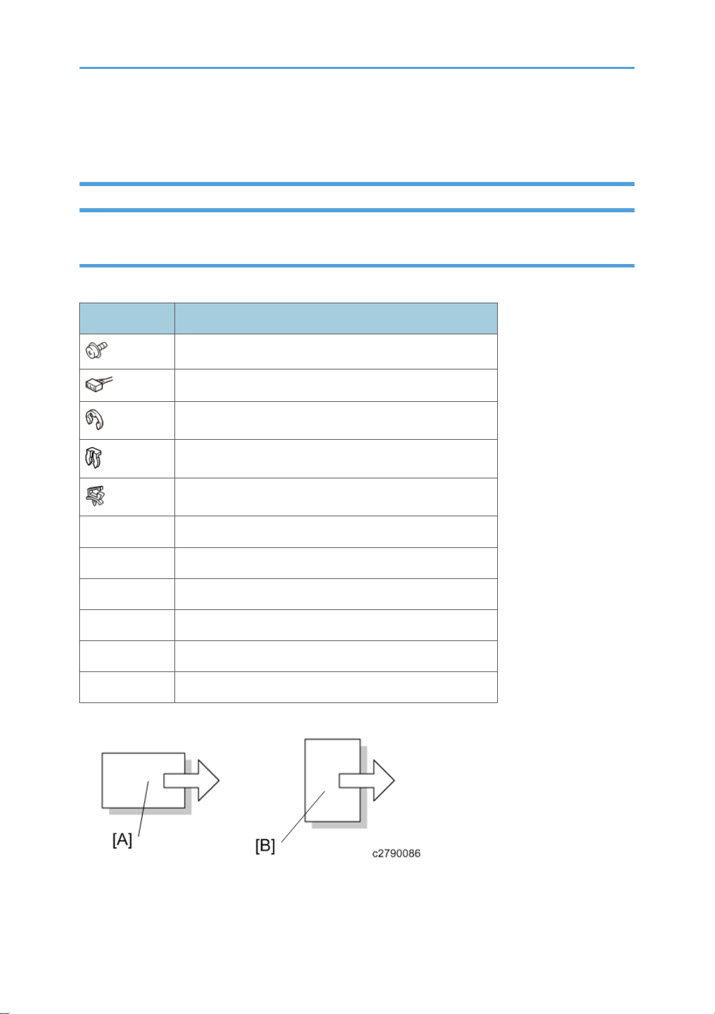
This is a list of symbols and abbreviations used in this manual.
Symbol What it means
Screw
Connector
E-ring
Clip ring
Harness clamp
FFC Flexible Film Cable
JG Junction Gate
LE Leading Edge of paper
LEF Long Edge Feed
SEF Short Edge Feed
TE Trailing Edge of paper
[A] Short Edge Feed (SEF)
[B] Long Edge Feed (LEF)
1
Page 4

Warnings, Cautions, Notes
In this manual, the following important symbols and notations are used.
• A Warning indicates a potentially hazardous situation. Failure to obey a Warning could result in
death or serious injury.
• A Caution indicates a potentially hazardous situation. Failure to obey a Caution could result in
minor or moderate injury or damage to the machine or other property.
• Obey these guidelines to avoid problems such as misfeeds, damage to originals, loss of valuable
data and to prevent damage to the machine.
• This information provides tips and advice about how to best service the machine.
Responsibilities of the Customer Engineer
Reference Material for Maintenance
• Maintenance shall be done using the special tools and procedures prescribed for maintenance of
the machine described in the reference materials (service manuals, technical bulletins, operating
instructions, and safety guidelines for customer engineers).
Use only consumable supplies and replacement parts designed for use of the machine.
•
The Aim of Anti-tip Components and Precautions
The anti-tip components are necessary for meeting the requirements of IEC60950-1, the international
standard for safety.
The aim of these components is to prevent the products, which are heavy in weight, from toppling as a
result of people running into or leaning onto the products, which can lead to serious accidents such as
persons becoming trapped under the product. (U.S.: UL60950-1, Europe: EN60950-1)
Therefore, removal of such components must always be with the consent of the customer.
Do not remove them at your own judgment.
2
Page 5

TABLE OF CONTENTS
Safety, Conventions, Trademarks......................................................................................................................1
Conventions.................................................................................................................................................... 1
Common Terms...................................................................................................................................... 1
Warnings, Cautions, Notes...........................................................................................................................2
Responsibilities of the Customer Engineer.................................................................................................... 2
Reference Material for Maintenance...................................................................................................2
The Aim of Anti-tip Components and Precautions....................................................................................... 2
1. Replacement and Adjustment
Removing Trays...................................................................................................................................................5
Door and Covers................................................................................................................................................ 7
Front Cover..................................................................................................................................................... 7
Rear Cover......................................................................................................................................................7
Top Cover....................................................................................................................................................... 8
Side Cover...................................................................................................................................................... 8
Left Top Cover.................................................................................................................................................9
Right Top Cover..............................................................................................................................................9
Left Rear Cover.............................................................................................................................................10
Right Rear Cover..........................................................................................................................................10
Right Cover...................................................................................................................................................11
Inner Covers................................................................................................................................................. 11
Inner Upper Cover.............................................................................................................................. 11
Inner Lower Cover...............................................................................................................................12
Paper Feed........................................................................................................................................................13
Paper Feed Units..........................................................................................................................................13
When reinstalling the paper feed unit............................................................................................... 13
Paper Feed, Separation and Pickup Rollers.............................................................................................. 14
Top Tray (Tray 1)................................................................................................................................ 14
Middle Tray (Tray 2)...........................................................................................................................16
Bottom Tray (Tray 3)........................................................................................................................... 18
LCIT Motors.......................................................................................................................................................22
Transport Motors, LCIT Exit Motor............................................................................................................. 22
1st, 2nd, and 3rd Transport Motors ..................................................................................22
LCIT Exit Motor ...............................................................................................................................22
3
Page 6

Feed Motors, Grip Motors................................................................................................................. 23
Reinstallation........................................................................................................................................
Lift Motors..................................................................................................................................................... 24
1st, 3rd Lift Motors..............................................................................................................................24
2nd Lift Motor......................................................................................................................................25
Exit Roller Lift Motor.....................................................................................................................................26
Cooling Fan .................................................................................................................................................27
Electrical Components..................................................................................................................................... 29
Paper Feed and End Sensors......................................................................................................................29
When reinstalling the sensor bracket.................................................................................................29
Lift Sensor......................................................................................................................................................30
LCIT Exit Sensor............................................................................................................................................31
Exit Roller Lift Sensor....................................................................................................................................31
Removing the Vertical Feed Unit.................................................................................................................32
1st Transport, 1st Relay Upper, Lower Sensors.........................................................................................34
2nd Relay Sensor, 2nd Transport Sensor.................................................................................................. 35
3rd Relay Sensor, 3rd Transport Sensor....................................................................................................36
Main Control Board.................................................................................................................................... 36
24
Paper Height, Paper Width Sensors...........................................................................................................37
Paper Height Sensors..........................................................................................................................37
Paper Width Sensors.......................................................................................................................... 37
Adjustment........................................................................................................................................................ 39
Side Registration Adjustment.......................................................................................................................39
Double Feed Problem from LCIT........................................................................................................ 39
4
Page 7
1. Replacement and Adjustment
Removing Trays
• Tray 2 weighs 27 kg (60 lb) empty. Trays 1 and 3 weigh 20 kg (44 lb) each empty.
• To prevent damage to the tray and personal injury, never attempt to lift a tray alone or without
attaching the carrying handles, especially if a tray is loaded with paper.
• Two people on each side of the tray should lift the carrying handles together to lift and move the
tray.
• Never remove the tray if the LCIT has not been docked to the copier. Removing the tray while the
LCIT is standing alone can unbalance the LCIT and cause it to fall over.
• Only one set of carrying handles is attached to the side of Tray 2. Follow the procedure below to
attach and use these handles to move Tray 1, 2, or 3.
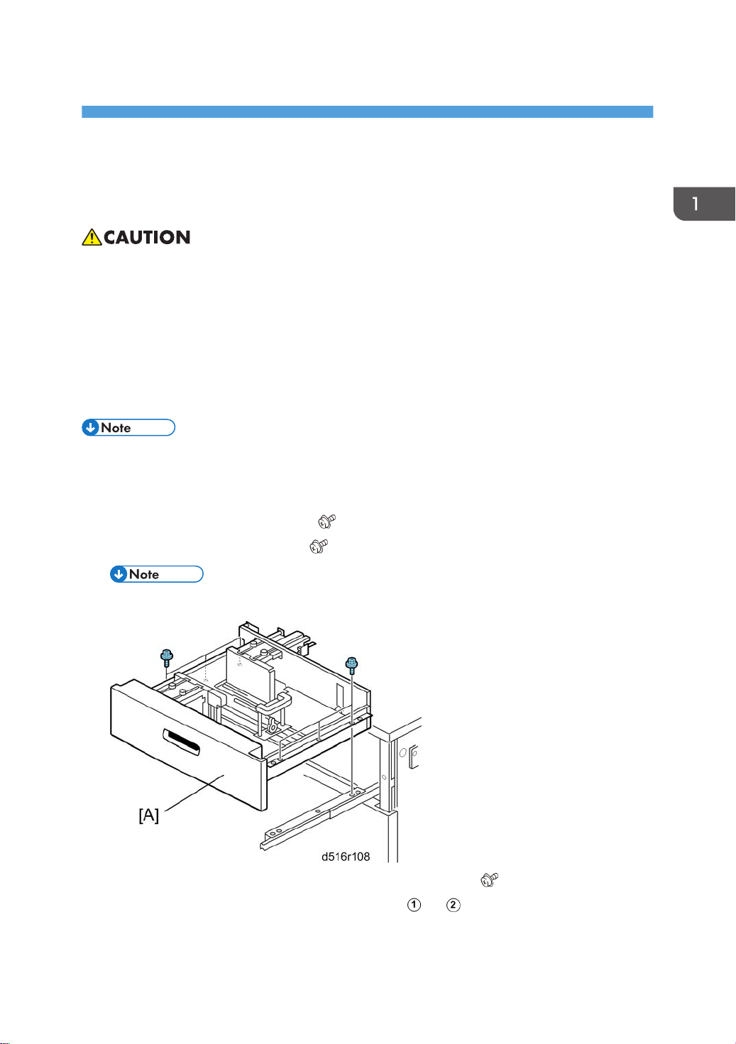
1. Pull the tray [A] out of the LCIT until it stops.
2. Remove the screws from the right rail ( x3)
3. Remove the screws from the left rail ( x3)
• You do not need to remove screw for the stopper pin bracket at the back of the left rail.
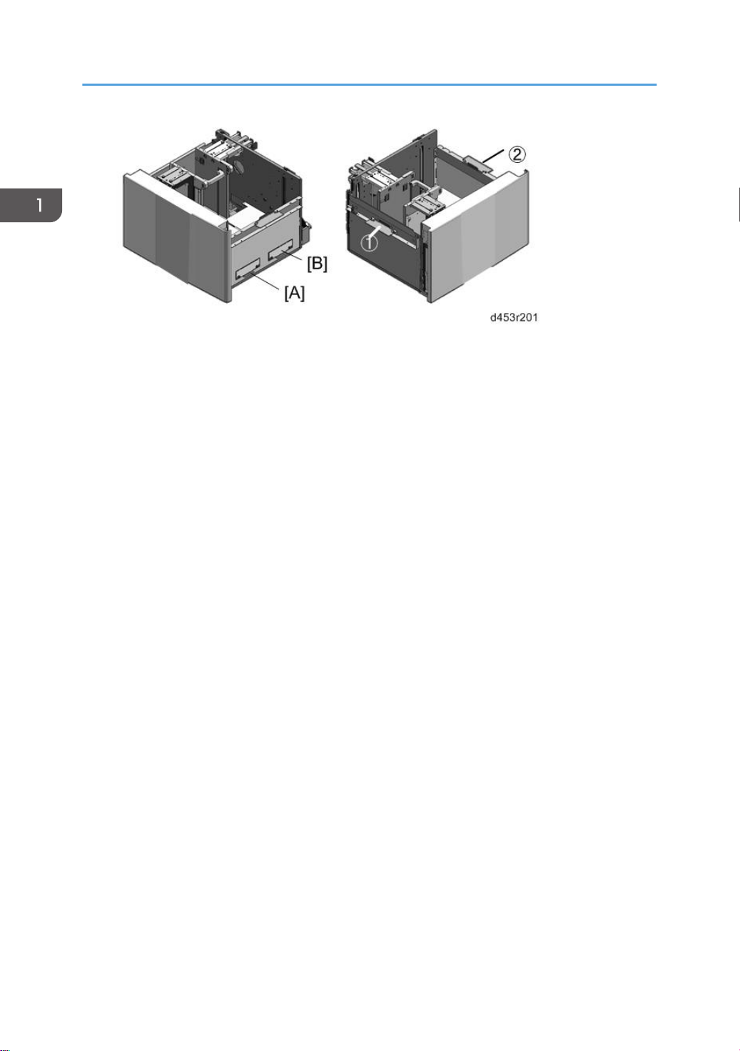
4. Remove carrying handles [A] and [B] from the right side of the tray ( x 2 ea.)
5.
Use the same screws to attach the carrying handles at
6.
With one person on each side of the tray, lift it carefully and remove it from the rails.
and .
5
Page 8
1. Replacement and Adjustment
6
Page 9
Door and Covers
Front Cover
1. Open the front door [A].
Door and Covers
2. Front cover [A] ( x2)
Rear Cover
1. Rear cover [A] ( x2)
7
Page 10
1. Replacement and Adjustment
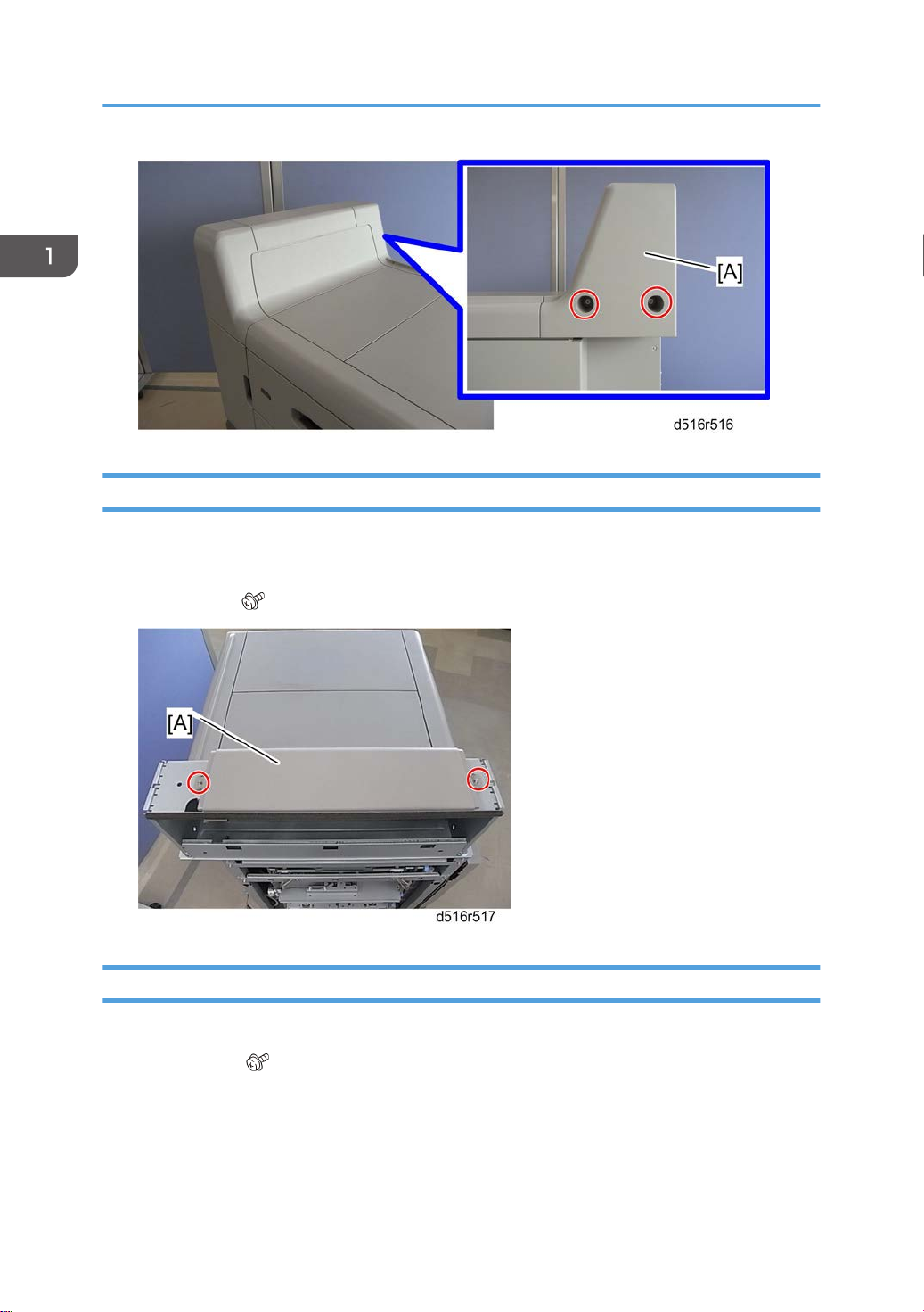
Top Cover
1. Front cover (page 7 "Front Cover")
Rear cover (page 7 "Rear Cover")
2.
3. Top cover [A] (
x2)
Side Cover
1. Top cover (page 8 "Top Cover")
Side cover [A] (
2.
x2)
8
Page 11
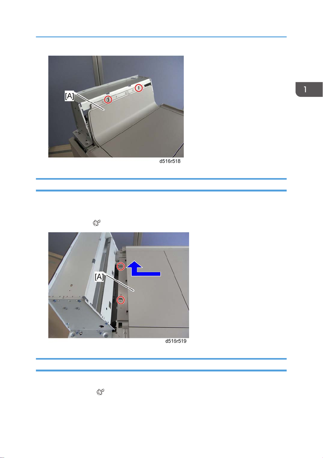
Left Top Cover
1. Top cover (page 8 "Top Cover")
Door and Covers
Side cover (page 8 "Side Cover")
2.
3. Left top cover [A] (
x2)
Right Top Cover
1. Left top cover (page 9 "Left Top Cover")
Right top cover [A] (
2.
x2)
9
Page 12
1. Replacement and Adjustment
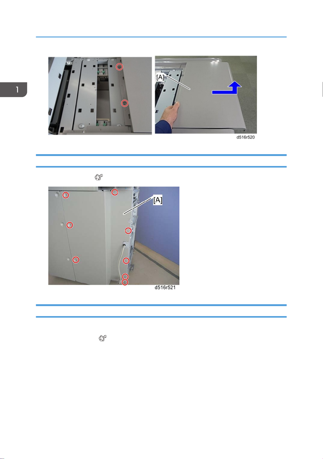
Left Rear Cover
1. Left rear cover [A] ( x8)
Right Rear Cover
1. Left rear cover (page 10 "Left Rear Cover")
2.
Right rear cover [A] (
10
x6)
Page 13
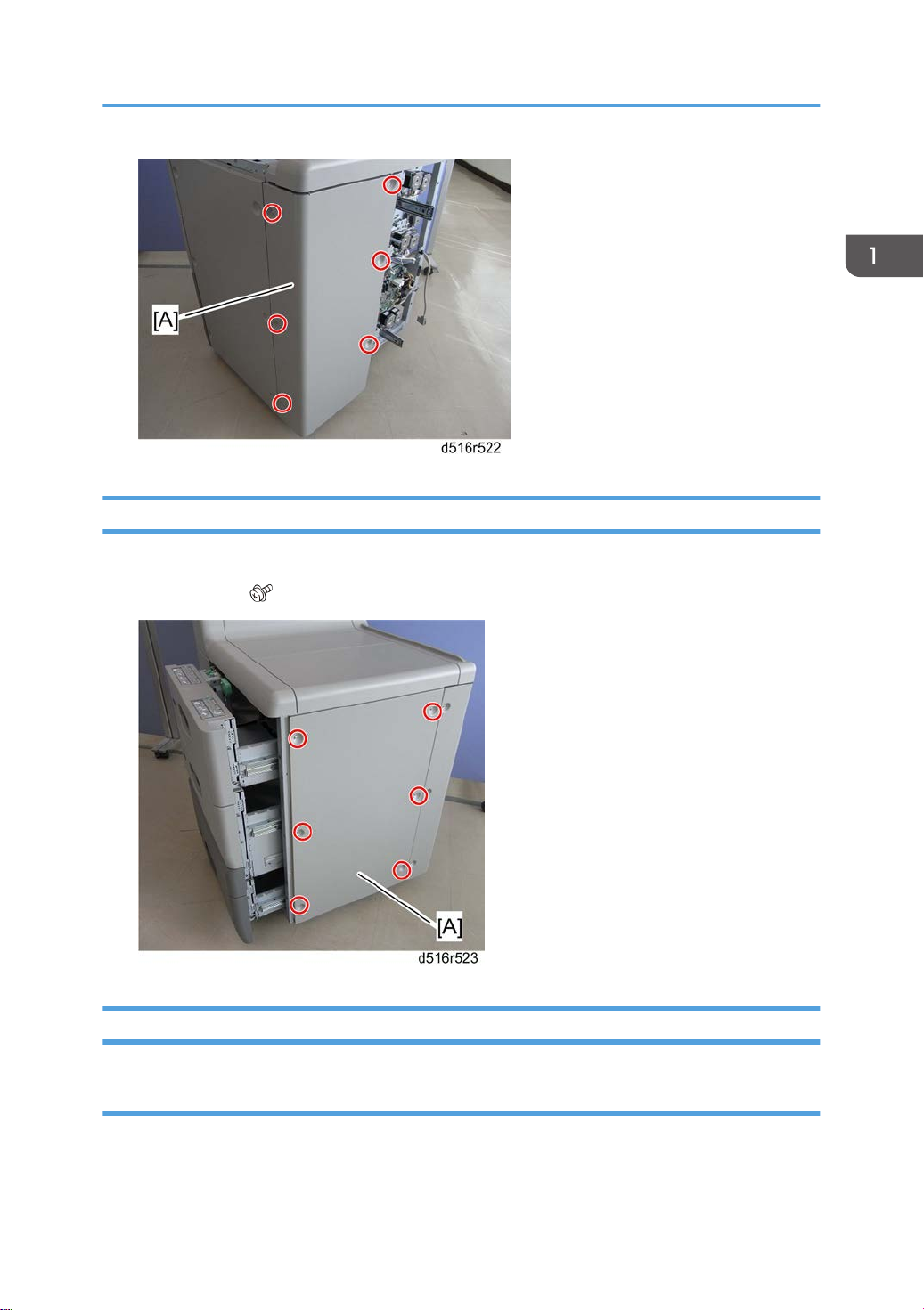
Right Cover
1. Pull all the LCIT trays out a short distance.
Right cover [A] (
2.
x6)
Door and Covers
Inner Covers
Inner Upper Cover
1. Open the front door.
Pull down the U1 lever [A].
2.
11
Page 14

1. Replacement and Adjustment
3. Remove:
Knob [B] ( x1)
Inner upper cover [C] ( x2)
Inner Lower Cover
1. Open the front door.
Inner lower cover [A] (
2.
x2)
12
Page 15

Paper Feed
Paper Feed Units
1. Pull out the top, middle or bottom tray.
Inner upper or lower cover (page 11 "Inner Covers")
2.
• For the paper feed unit in the top tray or middle tray, remove the inner upper cover.
• For the paper feed unit in the bottom tray, remove the inner lower cover.
Paper Feed
3. Pull the paper feed unit [A] (
Stopper bracket [B] (
4.
5. Pull the paper feed unit [A] out fully, and then lift it.
x 2).
x 1)
When reinstalling the paper feed unit
When reinstalling the paper feed unit, align the cutout in the slide rail with the stud screw [A], and then
install the paper feed unit.
13
Page 16

1. Replacement and Adjustment
Paper Feed, Separation and Pickup Rollers
Top Tray (Tray 1)
• Before doing this procedure, turn off the main machine and disconnect it from its power source.
Open the front door [A].
1.
2. Pull out the top tray [B] until it stops.
3. Side plate [A] ( x 2)
14
Page 17

4. Pull the paper feed unit [A] ( x 2).
Paper Feed
5. Slide the sensor bracket [A] to the front ( x 1).
• Note the original position of this bracket. It must be re-installed at its original position.
15
Page 18

1. Replacement and Adjustment
6. Remove:
[A]: Paper feed roller ( x 1)
[B]: Separation roller ( x 1)
[C]: Pickup roller ( x 1)
Middle Tray (Tray 2)
• Before doing this procedure, turn off the main machine and disconnect it from its power source.
1.
Open the front door [A].
2. Pull out the middle tray [B].
16
Page 19

3. Side plate [A] ( x 2)
Paper Feed
4. Pull the paper feed unit [A] ( x 2).
17
Page 20

1. Replacement and Adjustment
5. Slide the sensor bracket [A] to the front ( x 1).
• Note the original position of this bracket. It must be re-installed at its original position.
6. Remove:
[A]: Paper feed roller ( x 1)
[B]: Separation roller ( x 1)
[C]: Pickup roller ( x 1)
Bottom Tray (Tray 3)
18
• Before doing this procedure, turn off the main machine and disconnect it from its power source.
1.
Open the front door [A].
Page 21

2. Pull out the bottom tray [B].
3. Paper end fence [A] if it is stored here.
Paper Feed
4. Side plate [A] ( x 2)
19
Page 22

1. Replacement and Adjustment
5. Pull the paper feed unit [A] ( x 2).
20
6. Slide the sensor bracket [A] to the front ( x 1).
• Note the original position of this bracket. It must be re-installed at its original position.
Page 23

7. Remove:
[A]: Paper feed roller ( x 1)
[B]: Separation roller ( x 1)
[C]: Pickup roller ( x 1)
Paper Feed
21
Page 24

1. Replacement and Adjustment
LCIT Motors
Transport Motors, LCIT Exit Motor
1st, 2nd, and 3rd Transport Motors
1. Left rear cover (page 10 "Left Rear Cover")
Motor unit [A] (
2.
Motor [B] (
3.
x1, x1, x2)
x4)
LCIT Exit Motor
1. Left rear cover (page 10 "Left Rear Cover")
2.
3.
22
Motor unit [A] (
Motor [B] (
x1, x1, x2)
x4)
Page 25

LCIT Motors
Feed Motors, Grip Motors
Each paper feed unit has a pick-up feed motor and a grip motor . The removal procedure is the
same for each feed tray.
1.
Left rear cover (page 10 "Left Rear Cover")
2. Motor unit [A] (
x4, x2, x2)
3. Springs (x2) [A] (First, loosen the screws ( x2) , .)
Paper feed motor [B] (
4.
Grip motor [C] (
5.
x2, x1)
x2, x1)
23
Page 26

1. Replacement and Adjustment
Reinstallation
Attach the tension spring and then tighten the screws to tighten the belts.
Lift Motors
1st, 3rd Lift Motors
The procedure for removing the 1st and 3rd lift motors is the same.
1.
Right rear cover (page 10 "Right Rear Cover")
2. Motor unit [A] (
3.
1st (or 3rd) lift motor [B] (
x 3, x1)
x4, x1, Coupling x1, x1)
24
Page 27

2nd Lift Motor
LCIT Motors
1. Right rear cover (page 10 "Right Rear Cover")
2.
Motor unit [A] (
x 5, x1)
3. 2nd lift motor [A] ( x 2)
25
Page 28

1. Replacement and Adjustment
Exit Roller Lift Motor
1. Left rear cover (page 10 "Left Rear Cover")
The motor is located at [A].
2.
26
3. Disconnect the motor at [A] and [B] ( x1, x1)
Page 29

4. Disconnect the motor mount [A] ( x1).
Remove the motor [B].
5.
LCIT Motors
6. Separate the motor and bracket ( x2, x1).
Cooling Fan
1. Left rear cover (page 10 "Left Rear Cover")
Fan bracket [A] (
2.
x 2, x 1, x 1)
27
Page 30

1. Replacement and Adjustment
3. Cooling fan [A] ( x 2)
• When reinstalling the cooling fan, make sure that the cooling fan is installed with its decals
facing upward.
28
Page 31

Electrical Components
Paper Feed and End Sensors
1. Pull out the paper feed unit
Sensor bracket [A] (
2.
3. Paper feed sensor [A] (hooks)
x1, black screw x1, x1, x 2)
Electrical Components
4.
Paper end sensor [B] (hooks)
When reinstalling the sensor bracket
• Make sure that the white connector is connected to the paper feed sensor and the red connector is
connected to the paper end sensor.
•
Use two holes [A] when attaching the sensor bracket. Do not use the hole [B].
29
Page 32

1. Replacement and Adjustment
Lift Sensor
1. Paper feed unit (page 13 "Paper Feed Units")
Sensor bracket [A] (
2.
x1, x1, x1)
30
3. Lift sensor [A] ( x3)
Page 33

LCIT Exit Sensor
1. Disconnect the LCIT from the main machine.
Exit sensor unit [A] (
2.
x1, x1)
Electrical Components
Exit sensor [B]
3.
Exit Roller Lift Sensor
1. Disconnect the LCIT from the main machine.
31
Page 34

1. Replacement and Adjustment
2. Sensor bracket [A] ( x1)
3. Exit roller lift sensor [A] ( x1, x4)
Removing the Vertical Feed Unit
1. Open the front door.
Remove:
2.
• Inner upper cover (page 11 "Inner Covers")
• Inner lower cover (page 11 "Inner Covers")
• Left rear cover (page 10 "Left Rear Cover")
3. Disconnect the harness clamps
32
and ( x2).
Page 35

4. Disconnect the motor harnesses , , ( x3, x11).
Electrical Components
5. Upper stay [A] ( x2)
6.
Lower stay [B] (
x2)
33
Page 36

1. Replacement and Adjustment
7. Vertical feed unit [A] ( x6)
1st Transport, 1st Relay Upper, Lower Sensors
1. Vertical feed unit (page 32 "Removing the Vertical Feed Unit")
2.
Remove:
1st Transport sensor [A]: (
1st Relay sensor – upper [B] ( x1, x1)
1st Relay sensor – lower [C] ( x1, x1)
34
x1, x1)
Page 37

Electrical Components
2nd Relay Sensor, 2nd Transport Sensor
1. Vertical feed unit (page 32 "Removing the Vertical Feed Unit")
2.
Remove:
2nd Relay sensor [A] (
2nd Transport sensor [B] ( x1, x1)
x1, x1)
35
Page 38

1. Replacement and Adjustment
3rd Relay Sensor, 3rd Transport Sensor
1. Vertical feed unit (page 32 "Removing the Vertical Feed Unit")
Remove:
2.
3rd Relay sensor [A] (
3rd Transport sensor [B] ( x1, x1)
x1, x1)
Main Control Board
36
1. Left rear cover (page 10 "Left Rear Cover")
2.
Right rear cover (page 10 "Right Rear Cover")
3. Main control board [A] (
x7, x1, x All).
Page 39

Paper Height, Paper Width Sensors
Paper Height Sensors
1. Left rear cover (page 10 "Left Rear Cover")
Remove:
2.
Electrical Components
Paper height sensor unit [A] (
Clamp bracket [B] ( x2)
Paper height sensors (x 4) [C] ( x3, x 2 each)
x 2, x 4)
Paper Width Sensors
1. Left rear cover (page 10 "Left Rear Cover")
2. Remove:
Paper width sensor unit [A] ( x2, x 3)
Paper width sensors [B] ( x3, x2 each)
37
Page 40

1. Replacement and Adjustment
38
Page 41

Adjustment
Adjustment
Side Registration Adjustment
Normally the side registration of the image can be adjusted with SP1002-004 to -006 (Side-to-Side
Registration – Tray 1, 2, 3). When the punch hole positions are not aligned from a particular feed
station, adjust the side registration by changing the tray cover position for the tray, as described below.
Then adjust the side registration of the image with the SP1002.
Pull out the tray.
1.
2. Change the screw positions [A] at both the right and left sides as shown.
• Adjustment range: 0 ± 2.0 mm adjustment step: 0.5 mm/step
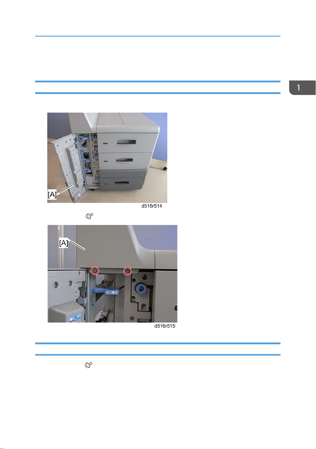
Double Feed Problem from LCIT
If double feed occurs several times when paper is fed from an LCIT (Tray 1, 2 or 3), try to change the
upper limit of the paper stack in the LCIT tray. Changing the upper limit of the paper stack in the LCIT
tray can improve paper separation for the paper stack in the LCIT tray.
1.
Remove the paper feed unit of the LCIT unit (page 13 "Paper Feed Units").
2. Loosen the screw on the paper lift sensor bracket [A].
3. Move the bracket 0.5 mm in the arrow direction as shown above.
39
Page 42

1. Replacement and Adjustment
4. Tighten the screw on the paper lift sensor bracket [A].
• To return the upper limit position to the default position, move the paper lift sensor bracket 0.5
mm to the opposite side.
Return the upper limit position to the default if a paper jam occurs at the paper feed sensor in
•
the LCIT.
40 EN
 Loading...