

Page 1

LCIT PB3170/PB3230
Machine Code: D695
Field Service Manual
April, 2013
Subject to change
Page 2

Page 3
Safety and Symbols
This manual uses several symbols and abbreviations. The meaning of those symbols and abbreviations
are as follows:
Clip ring
Screw
Connector
Clamp
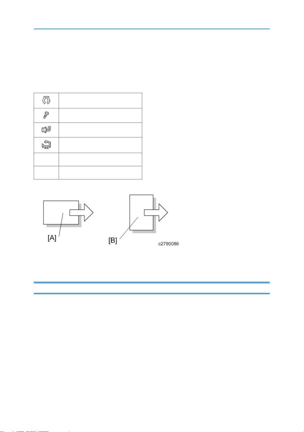
SEF Short Edge Feed
LEF Long Edge Feed
[A] Short Edge Feed (SEF)
[B] Long Edge Feed (LEF)
Trademarks
Microsoft®, Windows®, and MS-DOS® are registered trademarks of Microsoft Corporation in the
United States and /or other countries.
PostScript® is a registered trademark of Adobe Systems, Incorporated.
PCL® is a registered trademark of Hewlett-Packard Company.
Ethernet® is a registered trademark of Xerox Corporation.
PowerPC® is a registered trademark of International Business Machines Corporation.
Other product names used herein are for identification purposes only and may be trademarks of their
respective companies. We disclaim any and all rights involved with those marks.
1
Page 4

The Aim of Anti-tip Components and Precautions
The anti-tip components are necessary for meeting the requirements of IEC60950-1, the international
standard for safety.
The aim of these components is to prevent the products, which are heavy in weight, from toppling as a
result of people running into or leaning onto the products, which can lead to serious accidents such as
persons becoming trapped under the product. (U.S.: UL60950-1, Europe: EN60950-1)
Therefore, removal of such components must always be with the consent of the customer.
Do not remove them at your own judgment.
2
Page 5

TABLE OF CONTENTS
Safety and Symbols............................................................................................................................................1
Trademarks.....................................................................................................................................................1
The Aim of Anti-tip Components and Precautions.......................................................................................2
1. Replacement and Adjustment
Rear Cover..........................................................................................................................................................5
Right Tray, Left Tray............................................................................................................................................6
Left Tray Paper Sensor........................................................................................................................................8
Transfer Home Position Sensor..........................................................................................................................9
Controller Board...............................................................................................................................................11
Paper Feed Unit................................................................................................................................................12
Lower Limit Sensor............................................................................................................................................14
Tray Set Switch (Left)........................................................................................................................................15
Tray Set Switch (Right).....................................................................................................................................16
Tray Lift-Transport Unit.....................................................................................................................................17
Lift Motor...........................................................................................................................................................18
Transfer Motor..................................................................................................................................................19
Remaining Paper Sensor..................................................................................................................................20
Paper Feed Motor............................................................................................................................................22
Transport Motor...............................................................................................................................................23
Pick-up Roller, Feed Roller, Friction Roller.....................................................................................................24
Transport Sensor, Paper Fed Sensor, Paper End Sensor, Limit Sensor........................................................26
Side Fence........................................................................................................................................................29
3
Page 6

4
Page 7
1. Replacement and Adjustment
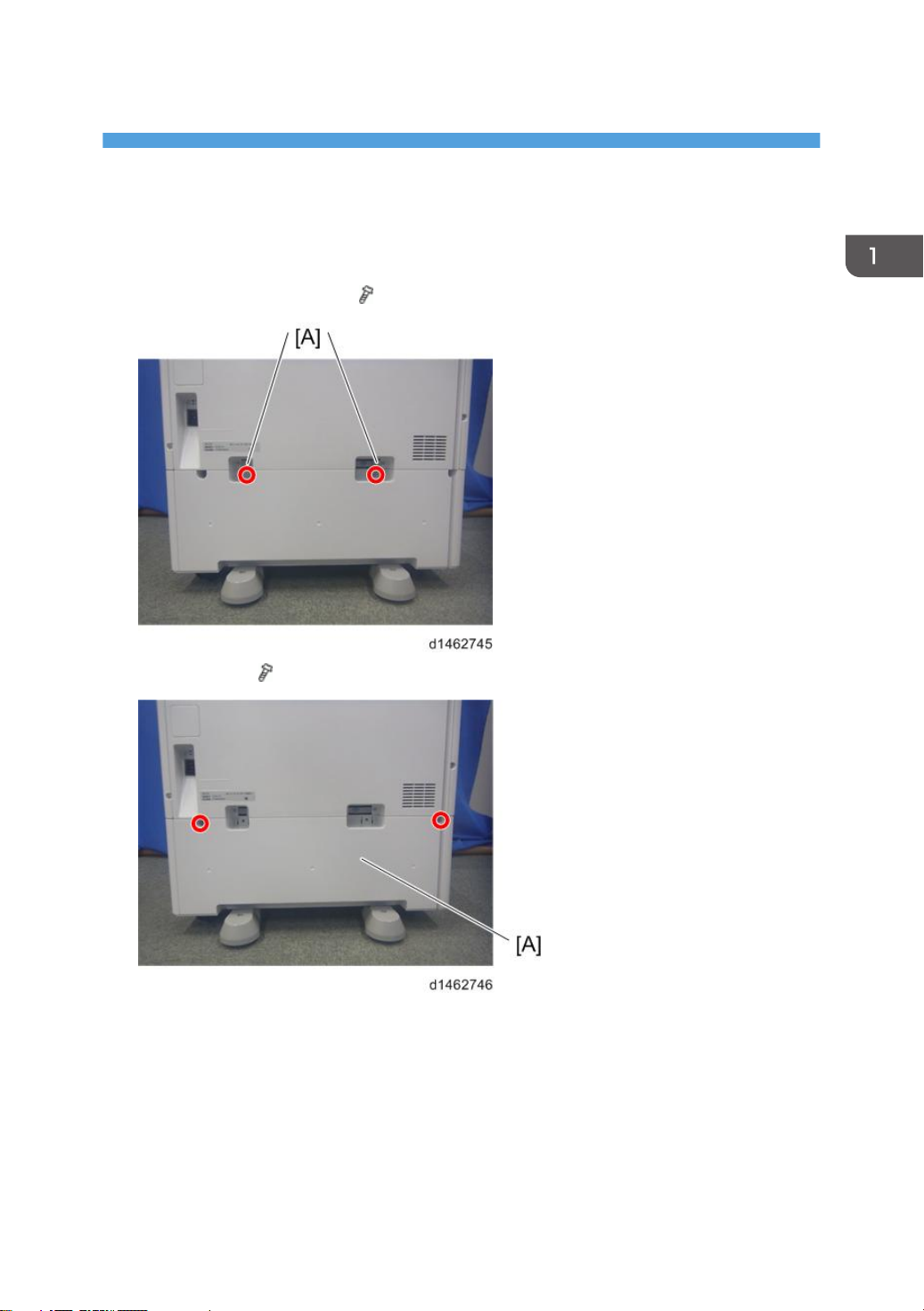
Rear Cover
1. Consolidated bracket [A] (2, ×2)
2. Rear cover [A] ( ×2)
5
Page 8
1. Replacement and Adjustment
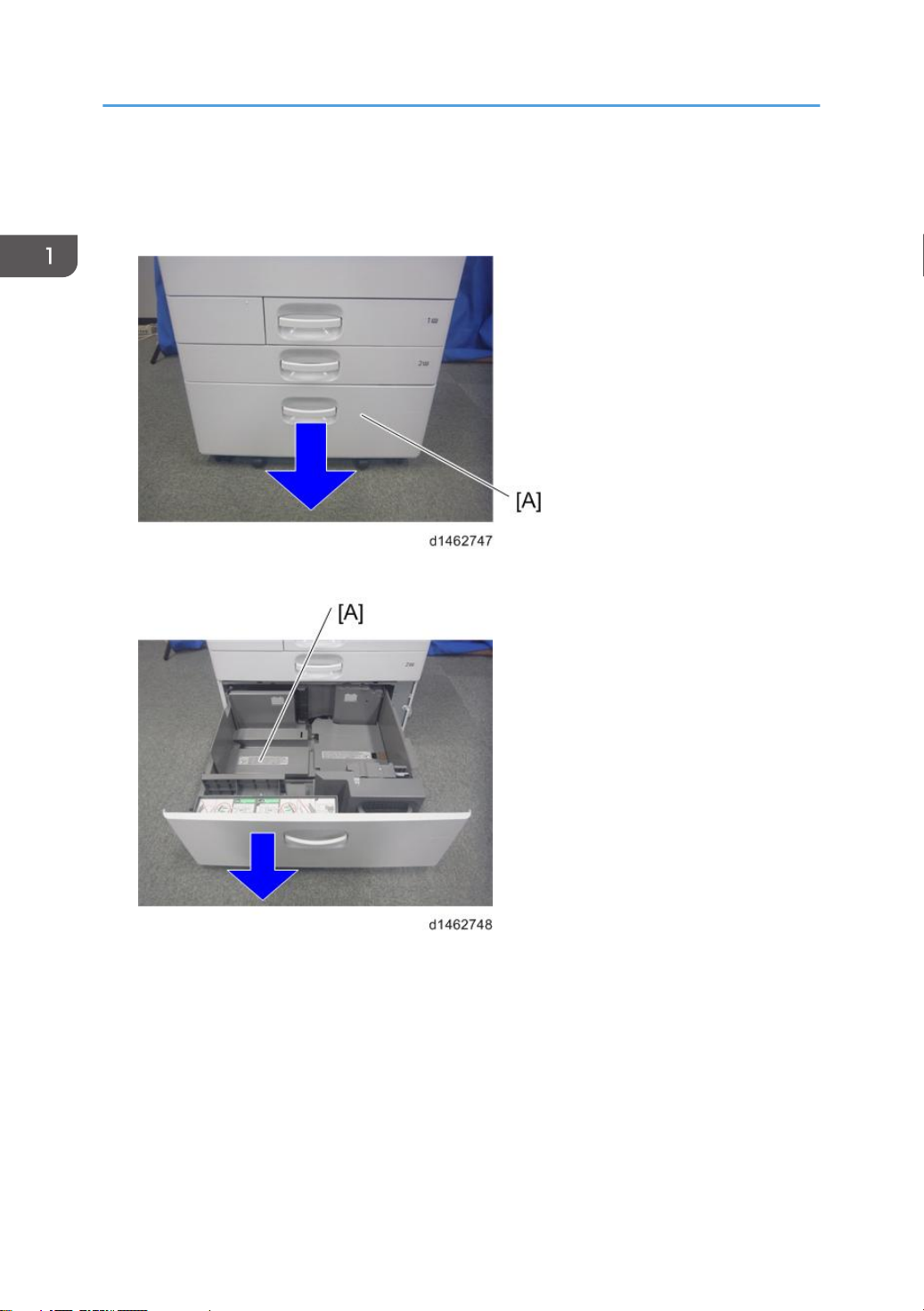
Right Tray, Left Tray
1. Pull out the paper tray.
2. Left Tray [A]
6
Page 9
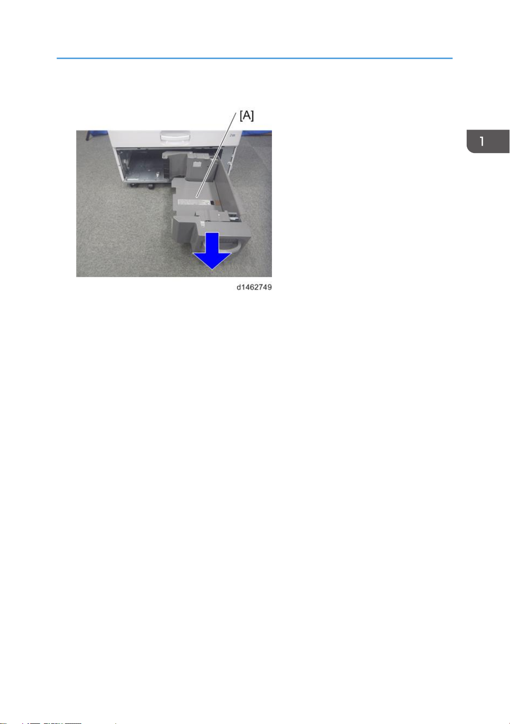
3. Right Tray [A]
Right Tray, Left Tray
7
Page 10
1. Replacement and Adjustment
Left Tray Paper Sensor
1. Left tray ( page 6)
2. Rear cover ( page 5)
3. Left tray paper sensor [A] ( ×1)
8
Page 11
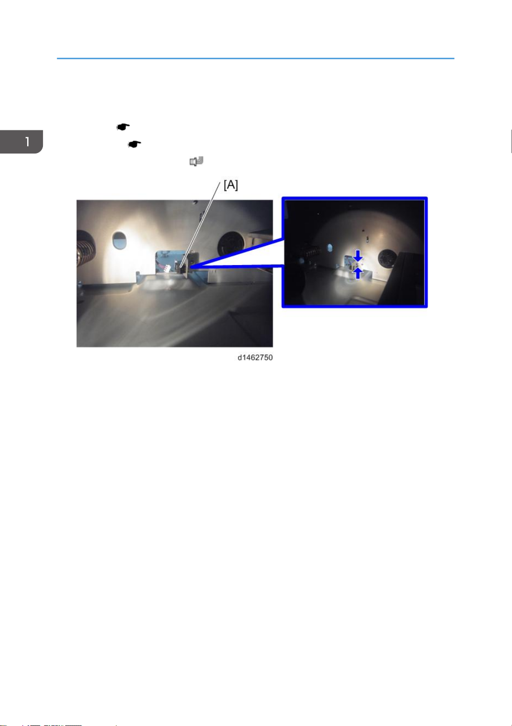
Transfer Home Position Sensor
1. Pull out the paper tray.
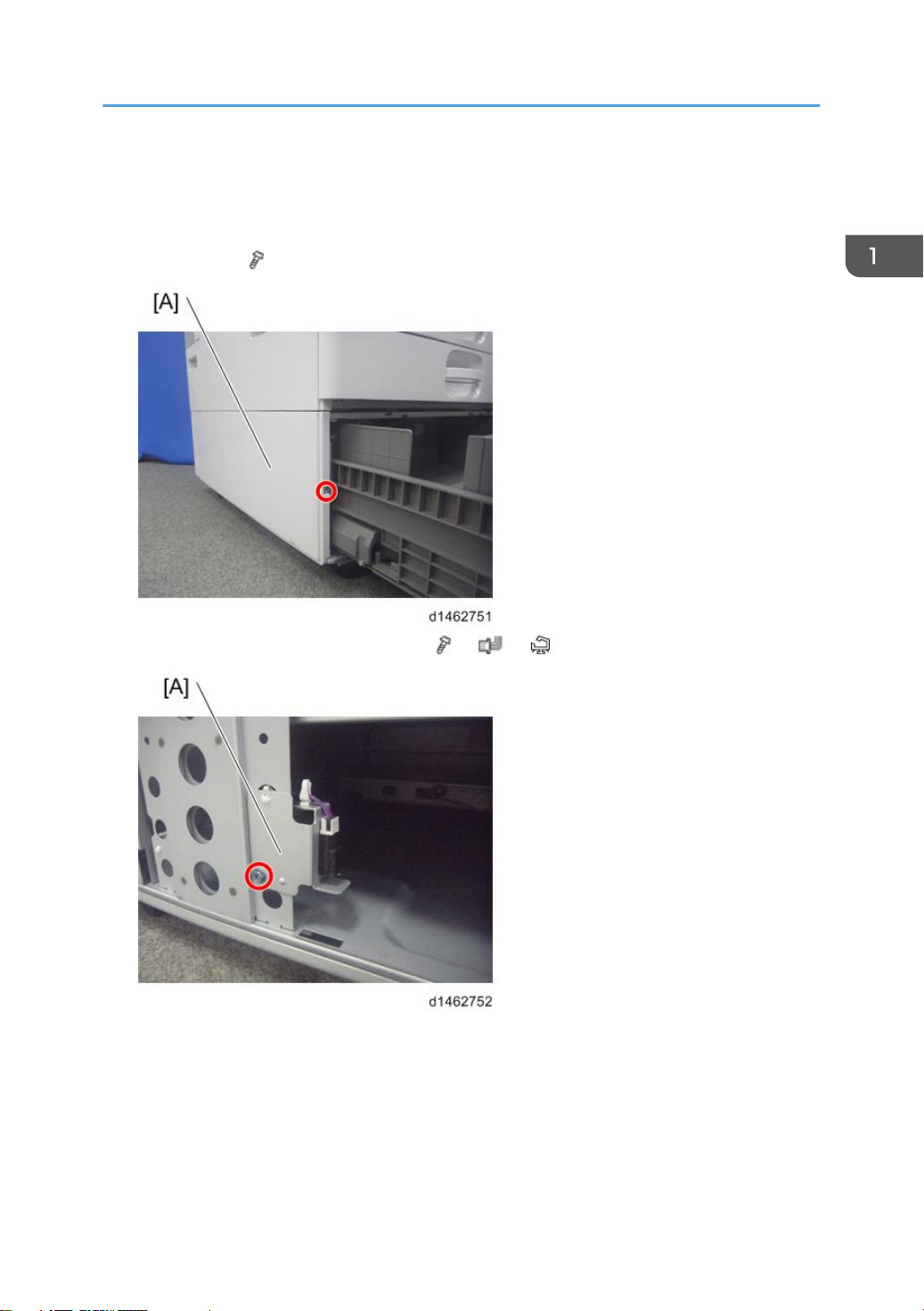
2. Left cover [A] ( ×1)
Transfer Home Position Sensor
3. Transfer home position sensor unit [A] ( ×1, ×1, ×2)
9
Page 12

1. Replacement and Adjustment
4. Transfer home position sensor [A]
10
Page 13

Controller Board
1. Rear cover ( page 5)
2. Controller board [A] ( ×4, ×9)
Controller Board
11
Page 14

1. Replacement and Adjustment
Paper Feed Unit
1. Pull out the paper tray.
2. Open the Transport cover [A].
3. Interlock switch cover [A] ( ×1)
12
Page 15

4. Paper feed guide plate [A]
5. Paper feed unit [A] ( ×2, ×1, ×1)
Paper Feed Unit
13
Page 16

1. Replacement and Adjustment
Lower Limit Sensor
1. Right tray (( page 6)
2. Rear cover ( page 5)
3. Tray lift-transport unit ( page 17)
4. Lower limit sensor [A] ( ×1)
14
Page 17

Tray Set Switch (Left)
1. Left tray ( page 6
2. Rear cover ( page 5)
3. Tray set switch (left) [A] ( ×1)
Tray Set Switch (Left)
15
Page 18

1. Replacement and Adjustment
Tray Set Switch (Right)
1. Right tray ( page 6)
2. Rear cover ( page 5)
3. Tray set switch (right) [A] ( ×1)
16
Page 19

Tray Lift-Transport Unit
1. Rear cover ( page 5)
2. Tray lift-transport unit [A] ( ×4, ×3, ×14)
Tray Lift-Transport Unit
17
Page 20

1. Replacement and Adjustment
Lift Motor
1. Tray lift-transport unit ( page 17)
2. Motor unit [A] ( ×5)
3. Lift motor [A] ( ×2)
18
Page 21

Transfer Motor
1. Motor unit ( page 18 "Lift Motor")
2. Transfer motor [A] ( ×2, ×1)
Transfer Motor
19
Page 22

1. Replacement and Adjustment
Remaining Paper Sensor
1. Rear cover ( page 5)
2. Remaining paper sensor unit [A] ( ×2, ×1, ×3)
3. Actuator [A]
20
Page 23

4. Remaining paper sensor [A]
Remaining Paper Sensor
21
Page 24

1. Replacement and Adjustment
Paper Feed Motor
1. Rear cover ( page 5)
2. Paper feed motor [A] ( ×2, ×1)
22
Page 25

Transport Motor
1. Rear cover ( page 5)
2. Transport motor [A] ( ×2, ×1)
Transport Motor
23
Page 26

1. Replacement and Adjustment
Pick-up Roller, Feed Roller, Friction Roller
1. Paper feed unit ( page 12)
2. Holder [A] ( ×1)
3. Pick-up roller [A]
24
Page 27

4. Feed roller [A]
5. Friction roller [A] ( ×1)
Pick-up Roller, Feed Roller, Friction Roller
25
Page 28

1. Replacement and Adjustment
Transport Sensor, Paper Fed Sensor, Paper End Sensor, Limit Sensor
1. Paper feed unit ( page 12)
2. Transport sensor unit [A] ( ×1, ×1)
3. Transport sensor [A]
26
Page 29

4. Paper feed sensor unit [A] ( ×1)
5. Paper feed sensor [A]
Transport Sensor, Paper Fed Sensor, Paper End Sensor, Limit Sensor
27
Page 30

1. Replacement and Adjustment
6. Press the claw shown by the blue circle, and remove the paper end sensor [A] ( ×1)
7. Limit sensor [A] ( ×1)
28
Page 31

Side Fence
Side Fence
1. Pull out the left tray and right tray.
2. Right tray side fence (front), [A], right tray side fence (rear) [B] and right tray end fence
[C] ( ×3)
29
Page 32

MEMO
30
Page 33

MEMO
31
Page 34

MEMO
32 EN
 Loading...