

Page 1

This manual contains detailed instructions and notes on the
operation and use of this product. For your safety and benefit,
read this manual carefully before using the product.
Original instructions
Appendix
Troubleshooting
Maintenance
Extended Functions
Basic Operations
Before Use
6.
5.
4.
3.
2.
1.
Operation Manual
Page 2

TABLE OF CONTENTS
Information ...........................................................................v
Introduction ...................................................................... v
Legal Prohibition .............................................................. v
CAUTION ............................................................................ vi
DISCLAIMER OF WARRANTY .......................................vi
FCC Statement (USA) .....................................................vi
Note to users in the state of California (USA) ..................vi
User Information on Electrical & Electronic Equipment ...vi
Note for the Battery and/or Accumulator Symbol
(For EU countries only) ...................................................vii
Warning on Class A Product ..........................................vii
DECLARATION OF CONFORMITY ..............................viii
Safety Precautions .............................................................. ix
Symbols ...........................................................................ix
Safety interlock ...............................................................xv
Warning labels ................................................................... xvi
Chapter 1
Before Use
Moving This Machine ........................................................1-2
Where to Install This Machine .......................................... 1-2
Working Environmental Temperature ............................... 1-2
Moving This Machine ........................................................1-2
Names of Parts and Functions ..........................................1-3
Front Side of the Machine ................................................ 1-3
Rear Side and Right Side of the Machine ........................ 1-4
Operation Panel ................................................................1-5
Signs on the power switch ................................................ 1-5
Heater ............................................................................... 1-6
Media sensor .................................................................... 1-6
Carriage ............................................................................ 1-7
Cutter blade and slot for cutting ........................................ 1-7
Connector of Temperature sensor/ Drying heater/
Take-up device .................................................................1-8
Capping station ................................................................. 1-8
Pinch rollers and Feed rollers ...........................................1-9
Connecting Cables ..........................................................1-10
Connecting USB2.0 Interface Cable ............................... 1-10
Connecting the power cable ...........................................1-11
Inserting ink cartridge ......................................................1-12
How to assemble ink cartridge ....................................... 1-12
About the ink that can be used with this machine .......... 1-14
Setting orders of ink cartridges ....................................... 1-15
Caution in handling of ink cartridges .............................. 1-17
Media ...............................................................................1-18
Usable sizes of media .................................................... 1-18
Caution in handling of medias ........................................ 1-18
About antistatic sheet ......................................................1-19
i
Page 3

Chapter 2
Basic Operations
Workflow ........................................................................... 2-2
Turning the Power ON/OFF .............................................. 2-3
Turning the Power ON ......................................................2-3
Turning the Power OFF ....................................................2-4
Setting a Media ................................................................. 2-5
Adjusting the Head Height ................................................2-5
Note for media setting .......................................................2-7
Setting a roll media ...........................................................2-8
Take-up device ...............................................................2-13
Setting leaf media ...........................................................2-14
Changing the printing origin ............................................2-16
Preparing for the Heaters ............................................... 2-17
Changing the Temperature Settings for the Heaters ......2-17
Checking the Heater Temperature .................................2-18
Changing the Temperature Settings for the
Drying Heater ..................................................................2-18
Test Feeding ................................................................... 2-19
Test Printing .................................................................... 2-20
Test Printing ....................................................................2-21
Head Cleaning ................................................................ 2-22
About head cleaning .......................................................2-22
Perform head cleaning depending on the test printing
result ...............................................................................2-22
Set the media feeding ..................................................... 2-23
Setting Feed Correction ..................................................2-23
Correct the ink drop position for bidirectional printing ..... 2-25
Printing Data ................................................................... 2-27
Checking the Status of Ink Cartridges ............................2-27
Checking the Status of Waste Ink Bottle ........................2-27
Starting a Printing Operation ..........................................2-28
Stopping a printing operation halfway ............................. 2-29
Deleting Received Data (Data Clear) .............................2-29
Behavior after printing has been completed ...................2-29
Cutting a media ...............................................................2-30
When [NEAR END] error occurs while printing ............... 2-30
When [INK END] error occurs while printing ................... 2-30
When a waste ink bottle confirmation message
appears while printing .....................................................2-31
Chapter 3
Extended Functions
List of Functions ................................................................ 3-2
Setting Logical Seek ......................................................... 3-3
Setting Drying Time .......................................................... 3-4
Setting Margins ................................................................. 3-5
Perform setting to reduce stripes between passes ........... 3-6
Setting Auto Cleaning ....................................................... 3-7
ii
Page 4

Setting nozzle face cleaning time ......................................3-8
Other Settings ...................................................................3-9
Machine Settings .............................................................3-10
Setting a AUTO Power-off ..............................................3-11
Setting the Display of Media Residual ............................ 3-12
Setting Time ................................................................... 3-14
Setting Units ................................................................... 3-15
Setting a KEY BUZZER .................................................. 3-16
Setting a LANGUAGE .................................................... 3-17
Initializing the Settings .....................................................3-18
Confirming Machine Information .....................................3-19
Displaying the Information ..............................................3-19
Check such as the machine version information ............ 3-21
Displaying the Information of this machine ..................... 3-21
Chapter 4
Maintenance
Maintenance ......................................................................4-2
Precautions for Maintenance ............................................ 4-2
About Cleaning Fluid ........................................................4-2
Cleaning the Exterior Surfaces ......................................... 4-3
Cleaning the Media Transfer Surface ............................... 4-3
Cleaning of after heater cover and pre heater cover ........ 4-3
Cleaning the Media Sensor .............................................. 4-4
Cleaning the Media Holder ...............................................4-4
Maintaining the Capping Station .......................................4-5
Cleaning the Wiper and Cap ............................................ 4-5
Washing the Ink Discharge Passage (DISWAY WASH) .. 4-8
When the Machine Is Not Used for a Long Time
(CUSTODY WASH) .......................................................... 4-9
Cleaning the Head and the Area around It (every day) ...4-13
Replacing method of absorber kit ....................................4-15
When Nozzle Clogging Cannot Be Solved ......................4-17
Washing of Head nozzle ................................................. 4-17
Washing nozzle surface .................................................4-20
Alternative nozzles for printing, when nozzles missing
can not be improved .......................................................4-22
Automatic Maintenance Function ....................................4-25
Setting the Refreshing Intervals ..................................... 4-25
Setting the Cleaning Intervals .........................................4-26
Setting the Cleaning Intervals .........................................4-27
Replacing consumables ..................................................4-28
Replacing the wiper ........................................................4-28
If a Waste Ink Bottle Confirmation Message Appears .... 4-29
Replacing the Cutter Blade .............................................4-32
Replacing the white ink filter ........................................... 4-34
When white ink filter becomes required to be replaced ..4-34
iii
Page 5

Chapter 5
Troubleshooting
Troubleshooting ................................................................ 5-2
Power does not turn on .....................................................5-2
The machine does not start printing .................................5-2
Media get jammed / media is soiled .................................5-3
[HEAT] or [CONSTANT] LED does not light up ................5-4
Image quality is poor .........................................................5-4
Nozzle is clogged ..............................................................5-5
Ink cartridge warning appears ..........................................5-5
When Error 618 to 61b occur ............................................5-6
When nozzle missing occurs due to ink mixture or
aeration .............................................................................5-7
Regular maintenance of white ink .....................................5-9
When media heaves up at feeding .................................5-10
When the feeding media is loosened and reached to the
floor .................................................................................5-10
Warning / Error Messages .............................................. 5-11
Warning messages .........................................................5-11
Error messages ..............................................................5-14
Chapter 6
Appendix
Specifications .................................................................... 6-2
Sheet for inquiry ................................................................ 6-5
Function Flowchart ........................................................... 6-6
Machine specifications ......................................................6-2
Ink specifications ..............................................................6-3
List of consumables ..........................................................6-4
iv
Page 6

Information
Introduction
Read this manual carefully before you use this machine and keep it handy for future reference. For safe and
correct use, be sure to read the Safety Precautions in this manual before using the machine.
Legal Prohibition
Do not copy or print any item for which reproduction is prohibited by law.
Copying or printing the following items is generally prohibited by local law:
bank notes, revenue stamps, bonds, stock certificates, bank drafts, checks, passports, driver's licenses.
The preceding list is meant as a guide only and is not inclusive. We assume no responsibility for its
completeness or accuracy. If you have any questions concerning the legality of copying or printing certain
items, consult with your legal advisor.
v
Page 7

CAUTION
DISCLAIMER OF WARRANTY
Contents of this manual are subject to change without prior notice.
To the maximum extent permitted by applicable laws, in no event will the manufacturer be liable for any
damages whatsoever arising out of failures of this machine, losses of the registered data, or the use of this
product and operation manuals provided with it. Make sure that you always copy or have backups of the data
registered in this machine. Documents or data might be erased due to your operational errors or malfunctions
of the machine. In no event will the manufacturer be responsible for any documents created by you using this
machine oranyresults from the data executed by you.
FCC Statement (USA)
Note:
This equipment has been tested and found to comply with the limits for a Class A digital devices, pursuant to
Part 15 of the FCC Rules. These limits are designed to provide reasonable protection against harmful
interference when the equipment is operated in a commercial environment. This equipment generates, uses
and can radiate radio frequency energy and, if not installed and used in accordance with the instruction
manual, may cause harmful interference to radio communications. Operation of this equipment in a residential
area is likely to cause harmful interference in which case the user will be required to correct the interference at
his own expense.
Caution:
Changes or modifications not expressly approved by the party responsible for compliance could void the user's
authority to operate the equipment.
Note to users in the state of California (USA)
Perchlorate Material - special handling may apply. See: www.dtsc.ca.gov/hazardouswaste/perchlorate
User Information on Electrical & Electronic Equipment
Users in the countries where this symbol shown in this section has been specified in national
law on collection and treatment of E-waste
Our Products contain high quality components and are designed to facilitate recycling.
Our products or product packaging are marked with the symbol below.
1
2
3
4
The symbol indicates that the product must not be treated as municipal waste. It must be disposed of
separately via the appropriate return and collection systems available. By following these instructions you
ensure that this product is treated correctly and help to reduce potential impacts on the environment and
human health, which could otherwise result from inappropriate handling. Recycling of products helps to
conserve natural resources and protect the environment.
For more detailed information on collection and recycling systems for this product, please contact the shop
where you purchased it, your local dealer or sales/service representatives.
All Other Users
If you wish to discard this product, please contact your local authorities, the shop where you bought this
product, your local dealer or sales/service representatives.
vi
5
6
Page 8
For Users in India
This product complies with the "India E-waste Rule 2011" and prohibits use of lead, mercury, hexavalent
chromium, polybrominated biphenyls or polybrominated diphenyl ethers in concentrations exceeding 0.1
weight % and 0.01 weight % for cadmium, except for the exemptions set in Schedule 2 of the Rule.
For Turkey only
complies with EEE regulation:
The system including supply and parts complies with Directive
Note for the Battery and/or Accumulator Symbol (For EU countries only)
In accordance with the Battery Directive 2006/66/EC Article 20 Information for end-users Annex II, the above
symbol is printed on batteries and accumulators.
This symbol means that in the European Union, used batteries and accumulators should be disposed of
separately from your household waste.
In the EU, there are separate collection systems for not only used electrical and electronic products but also
batteries and accumulators.
Please dispose of them correctly at your local community waste collection/recycling centre.
Warning on Class A Product
Warning:
This is a Class A product. In a domestic environment this product may cause radio interference in which case
the user may be required to take adequate measures.
vii
Page 9

CAUTION
DECLARATION OF CONFORMITY
We, RICOH CO., Ltd. at address 3-6, Naka-magome 1-Chome, Ohta-Ku, Tokyo 143-8555, Japan declare
under our sole responsibility that the product consisting of the following;
Product Name : Inkjet Printer
Model Name : Pro L4160, Pro L4130
to which this declaration relates is in conformity with the following standards.
EN 60950-1:2006+A11:2009+A1:2010+A12:2011
EN ISO 12100:2010
EN 60204-1:2006+A1:2009
EN 55022:2010 ClassA
EN 55024:2010
EN 61000-3-2:2006+A2:2009
EN 61000-3-3:2008
EN 62311:2008
EN 50581:2012
following the provisions of
EMC Directive 2004/108/EC
Low Voltage Directive 2006/95/EC
Machinery Directive 2006/42/EC
RoHS Directive 2011/65/EU
1
CE Mark is affixed in 2013
Place : Tokyo, Japan
Date : September 26, 2013
Importer:
Ricoh Europe PLC
20 Triton Street, London, NW1 3BF, U.K.
2
3
4
viii
5
6
Page 10
Safety Precautions
Symbols
Symbols are used in this Operation Manual for safe operation and for prevention of damage to the machine.
The indicated sign is different depending on the content of caution.
Symbols and their meanings are given below. Please follow these instructions as you read this manual.
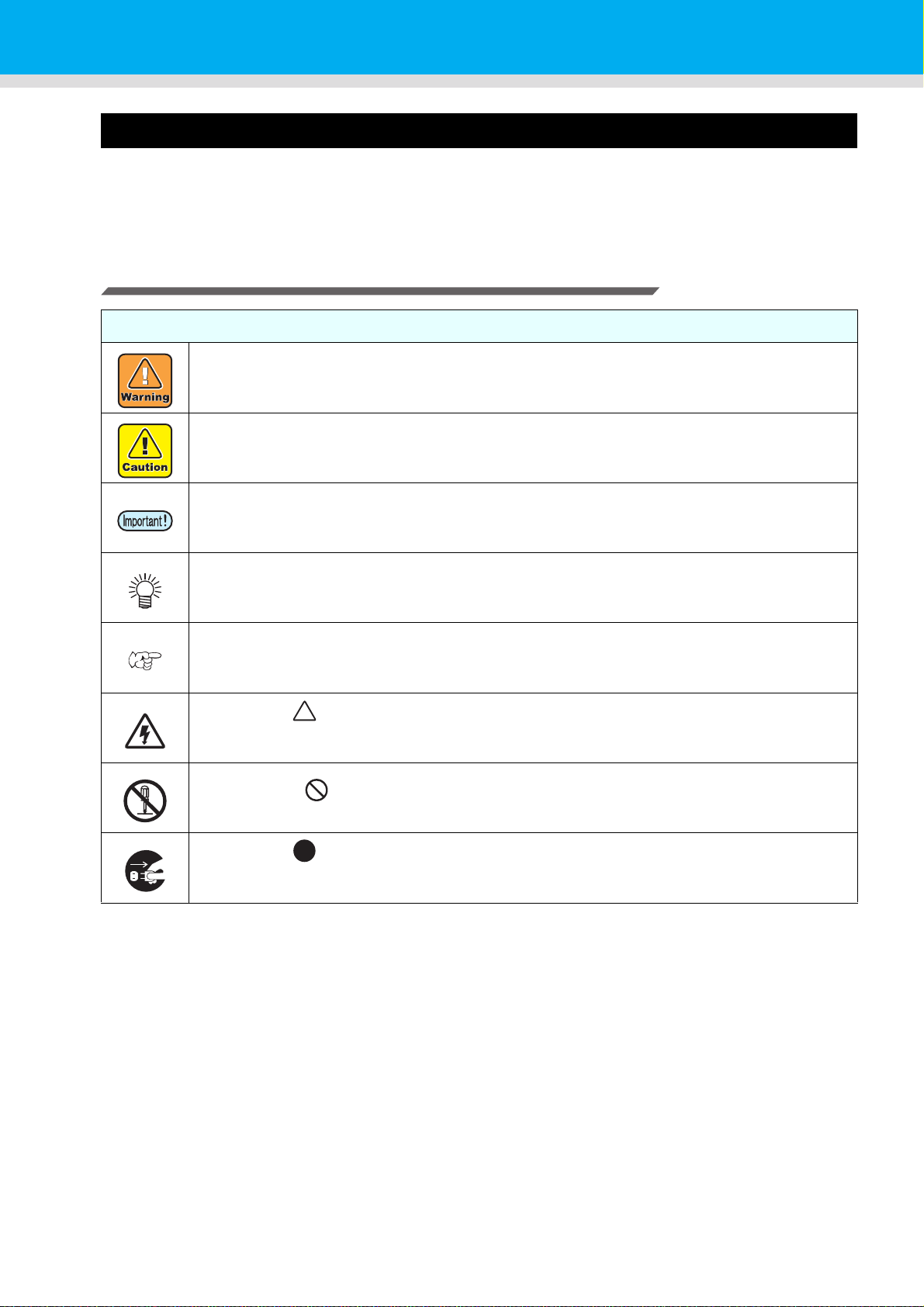
Examples of symbols
Meaning
Failure to observe the instructions given with this symbol can result in death or serious injuries
to personnel. Be sure to read it carefully and use it properly.
Failure to observe the instructions given with this symbol can result in injuries to personnel or
damage to property.
Important notes in use of this machine are given with this symbol. Understand the notes
thoroughly to operate the machine properly.
Useful information is given with this symbol. Refer to the information to operate the machine
properly.
Indicates the reference page for related contents.
The symbol " " indicates that the instructions must be observed as strictly as the CAUTION
instructions (including DANGER and WARNING instructions). A sign representing a precaution
(the sign shown at left warns of hazardous voltage) is shown in the triangle.
The symbol " " indicates that the action shown is prohibited. A sign representing a
prohibited action (the sign shown at left prohibits disassembly) is shown in or around the circle.
The symbol " " indicates that the action shown must be taken without fail or the instructions
must be observed without fail. A sign representing a particular instruction (the sign shown at left
instructs to unplug the cable from the wall outlet) is shown in the circle.
ix
Page 11
Safety Precautions
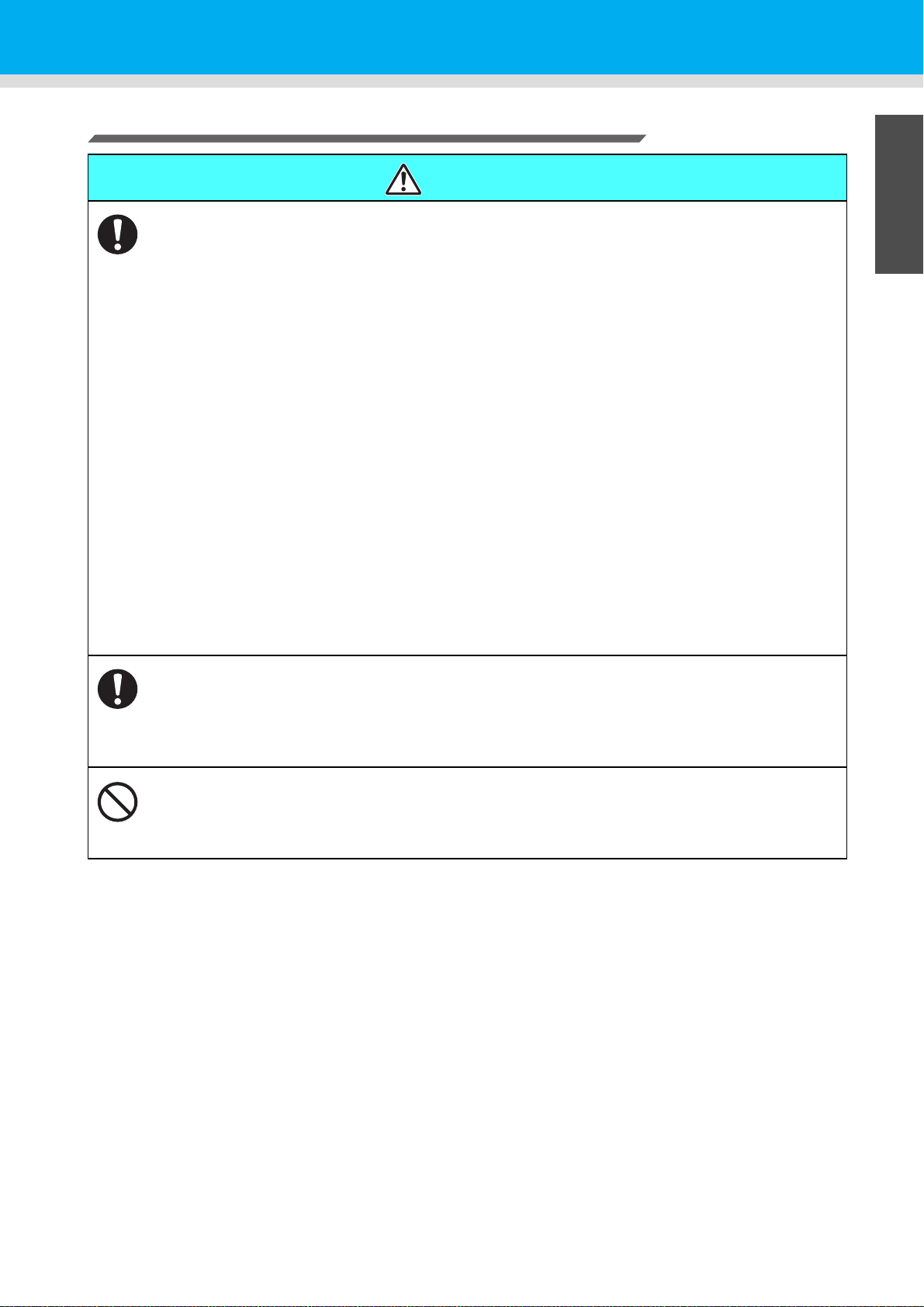
Warning for Use
WARNING
• The set of power cables provided with this machine is for use with this machine only, and cannot be
used with other electrical devices. Do not use any power cables other than the ones provided with the
machine. Failure to observe those instructions may result in fire or electric shocks.
• Take care not to damage, break or work upon the power cable. If a heavy material is placed on the
power cable, or if it is heated or pulled, the power cable can break, thus resulting in fire or electric
shocks.
• Do not use this machine in an environment where humidity is high or the machine may get wet. Using
the machine under such environment may result in fire or electric shock, or cause malfunction.
• Use of the machine under an abnormal condition where it produces smoke or strange smell can result
in fire or electric shocks. If such an abnormality is found, be sure to turn off the power switch
immediately and unplug the cable from the wall outlet. Check first that the machine no longer
produces smoke, and then contact your distributor or a sales office of RICOH for repair.
• Never repair your machine by yourself since it is very dangerous for you to do so.
• Never disassemble or remodel the main unit of the machine or the ink cartridge. Disassembly or
remodeling can result in an electric shock or breakdown of the machine.
• Take care that no dust or dirt sticks to Media Transfer Surface heaters. Dust and dirt sticking heaters
can cause fire.
• Do not use extension cords. Doing so may result in fire or electric shocks.
• Keep the power plug prong clear of any foreign object such as a piece of metal. Failure to do so may
result in a fire or electric shocks.
• Do not plug too may leads into a single socket. Doing so may result in fire or electric shocks.
• Do not use the machine if the power cord or plug is damaged. Using the machine with damaged power
cord may result in fire or electric shocks. Contact your service representative for replacement cord.
• Do not handle the power plug with wet hands. Doing so may result in electric shocks.
• Grasp by holding the plug itself when removing the power plug from wall outlet, and never hold by the
cord. Holding and pulling the cord may damage the cord, leading to fire or electric shocks.
Hazardous Moving Parts
• Keep Fingers and Other Body Parts Away
• If a foreign object such as a small piece of metal or a liquid such as water gets inside the machine, turn
off the machine and unplug the power cord immediately, then consult your service representative.
Continuing to use the machine without proper maintenance or repair may result in fire or electric
shocks.
• Do not use a flammable spray or solvent inside or around the machine. Doing so may result in fire or
electric shocks.
• Do not place a vase, flower pot, water glass, container with liquid such as water or chemicals inside, or
small metallic object near or on top of this machine. Liquid or foreign object may get inside the
machine, leading to fire or electric shocks.
1
2
3
4
5
6
x
Page 12

CAUTION
Handling of the power cable Power supply
• Connect to a socket-outlet with determinate
polarity.
• For Inlet 1 and 2, be sure to supply power
from the outlet of the same voltage.
• for PLUGGABLE EQUIPMENT, the socketoutlet shall be installed near the equipment
and shall be easily accessible.
• Unplug the cord from the wall outlet and
remove dust from the power plug
periodically, at least once a year. Failure to
do so may result in fire or electric shocks.
• Do not use the machine unless it is
connected to a power supply that satisfies
the displayed voltage condition.
• Check the voltage of the wall outlet and the
capacity of the circuit breaker before you
plug the power cords. Plug each power cord
to different outlet that has independent
circuit breaker. If you plug more than one
power cord to wall outlets that share the
same circuit breaker, the power may be cut
off by the breaker.
Heater
• Do not spill liquid on the Media Transfer
Surface as this may cause failure of the
heater or firing.
• Do not touch Media Transfer Surface heaters
with bare hand while it is hot; otherwise, you
can get burned.
Note on maintenance
• When cleaning the ink-station or the heads, make sure to wear the attached goggles and gloves.
• The gloves supplied with the machine are disposable. When all the gloves are expended, purchase an
equivalent product on the market.
Handling of ink
• Leave the breaker turned ON.
• Do not turn off the main power switch on the
right side of this machine.
• Keep ink away from an open flame. Also
keep the room well ventilated when you use
or handle ink.
• If you get ink in your eyes, immediately wash
your eyes with a lot of clean water for at least
15 minutes. In doing so, also wash eyes to
rinse ink away completely. Then, consult a
doctor as soon as possible.
• If anyone drinks ink by mistake, keep him or
her quiet and see a doctor immediately. Do
not allow him or her to swallow the vomit.
After that, contact the Poison Control Center.
• If you inhale a lot of vapor and feel bad,
immediately move to a location of fresh air
and then keep yourself warm and quiet.
Then, consult a doctor as soon as possible.
• Store ink cartridges in a place that is out of
the reach of children.
• Black and white cause serious eye irritation,
suspected of damaging fertility or the
unborn child, causes damage to the lungs
through prolonged or repeated exposure.
Please use protective equipment in order to
avoid exposure to liquid.
• Orange, green, cyan, magenta and yellow
cause serious eye irritation, suspected of
damaging fertility or the unborn child. Please
use protective equipment in order to avoid
exposure to liquid.
xi
• Do not to touch the sharp edge of the blade when replacing the cutter. Touching the sharp edge may
result in injury.
• Turn off the machine and unplug the power cord from the wall outlet for safety when moving the
machine.
Page 13

Notes on Handling the Machine
• Do not use the machine in a confined or poorly ventilated room.
• Keep the room well ventilated when using the machine.
• Do not use the machine under humid or dusty environment. Doing so may result in fire or electric
shocks.
• Do not place the machine on unstable or inclined surface. The machine may fall or topple over and
cause a damage or injury.
• There is a cutter inside the machine for cutting print media. Do not touch any other parts other than
the ones described in this manual when loading or replacing paper, or removing jammed paper.
Otherwise, it may cause an injury.
• Be careful not to get your fingers get caught inside the machine and injured when replacing print
paper.
• The dust collected inside the machine may result in fire or cause malfunction. If the machine has not
been cleaned for a long period of time, contact your service representative for cleaning the machine.
For the cleaning charge, consult your sales or service representative.
• Consult our service office in your area before moving this machine.
Safety Precautions
CAUTION
1
2
3
4
xii
5
6
Page 14
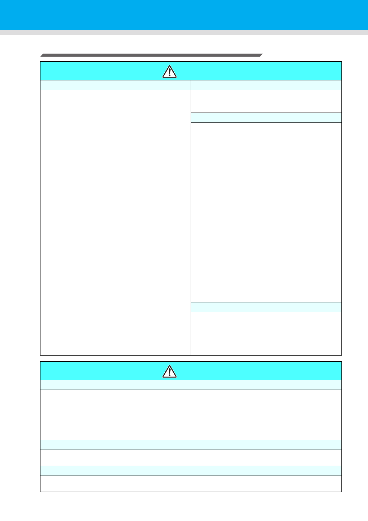
CAUTIONS and NOTES
Warning
Handling of ink cartridges Front cover and lever
• The safety evaluation of this machine assumes that
the ink recommended by this company is used. For
safe usage of this machine, use the ink recommend
by this company
• Never refill the ink pack and white ink cartridge with
ink. Refilled ink cartridge can cause a trouble.
Remember that RICOH assumes no responsibility for
any damage caused by the use of the ink cartridge
replenished with ink.
• If the ink cartridge is moved from a cold place to a
warm place, leave it in the room temperature for three
hours or more before using it.
• Open the ink cartridge just before installing it in the
machine. If it is opened and left for an extended
period of time, normal printing performance of the
machine may not be ensured.
• Make sure to store ink cartridges in a cool and dark
place.
• Store ink cartridges and waste ink bottle in a place
that is out of the reach of children.
• Be sure to thoroughly consume the ink in the ink
cartridge, once it is opened, within three months. If an
extended period of time has passed away after
opening the cartridge tank, printing quality would be
poor.
• Neither pound the Eco-cartridge nor shake it violently,
as doing so can cause leakage of ink.
• Do not touch or stain the contacts of the ink cartridge,
as doing so may cause damage to the print circuit
board.
• Consult your sales or service representative for
proper disposal of ink cartridge, ink pack, and waste
ink. Otherwise, commission an industrial waste
disposal company.
• Never open the front cover or raise the lever during
printing. Opening the cover or raising the lever will
abort printing.
Handling of media
• Use media recommended by RICOH to ensure
reliable, high-quality printing.
• Set the heater temperature to meet the characteristics
of the media.
Set the temperature of the Pre-heater, Print heater and
Post-heater according to the type and characteristics
of the media used. Automatic temperature setting can
be made on the operation panel by setting the profile
on the dedicated RIP. For setting on the RIP, refer to
the instruction manual for your RIP.
• Pay attention to the expansion and contraction of the
media.
Do not use media immediately after unpacking. The
media can be affected by the room temperature and
humidity, and thus it may expand and contract.The
media have to be left in the atmosphere in which they
are to be used for 30 minutes or more after unpacked.
• Do not use curled media.
The use of curled media can not only cause a media
jam but also affect print quality.
Straighten the sheet of media, if significantly curled,
before using it for printing. If a regular-sized coated
sheet of media is rolled and stored, the coated side
has to face outside.
• Do not leave the media with the heater ON for a long
time.
Protection of media from dust
• Store media in a bag. Wiping off dust accumulated on
media will adversely affect the media due to static
electricity.
• When leaving the workshop after the working hours,
do not leave any media on the roll hanger. If any
media is left on the roll hanger, it can get dusty.
Warning
Notes on maintenance
• It is strongly recommended to use the machine in a room that is not dusty.
• Keep the front cover closed even when the machine is not printing. If not, dust can accumulate on the nozzles
in the heads.
• Dust in the heads can also cause drops of ink to fall suddenly down on the media during printing. In such a
case, be sure to clean up the heads. (P.4-13 “Cleaning the Head and the Area around It (every day)”)
• When cleaning the ink-station or the heads, make sure to wear the attached gloves.
• Perform wiping (removal of dust and paper powder) of the capping station and wiper frequently.
Periodic replacement parts
• Some parts of this machine must be replaced with a new one periodically by service personnel. Be sure to
make a contract with your distributor or dealer for After sale service to ensure a long life of your machine.
Disposition of this machine
• Consult your sales or service representative for proper disposal of this machine. Otherwise, commission an
industrial waste disposal company.
xiii
Page 15
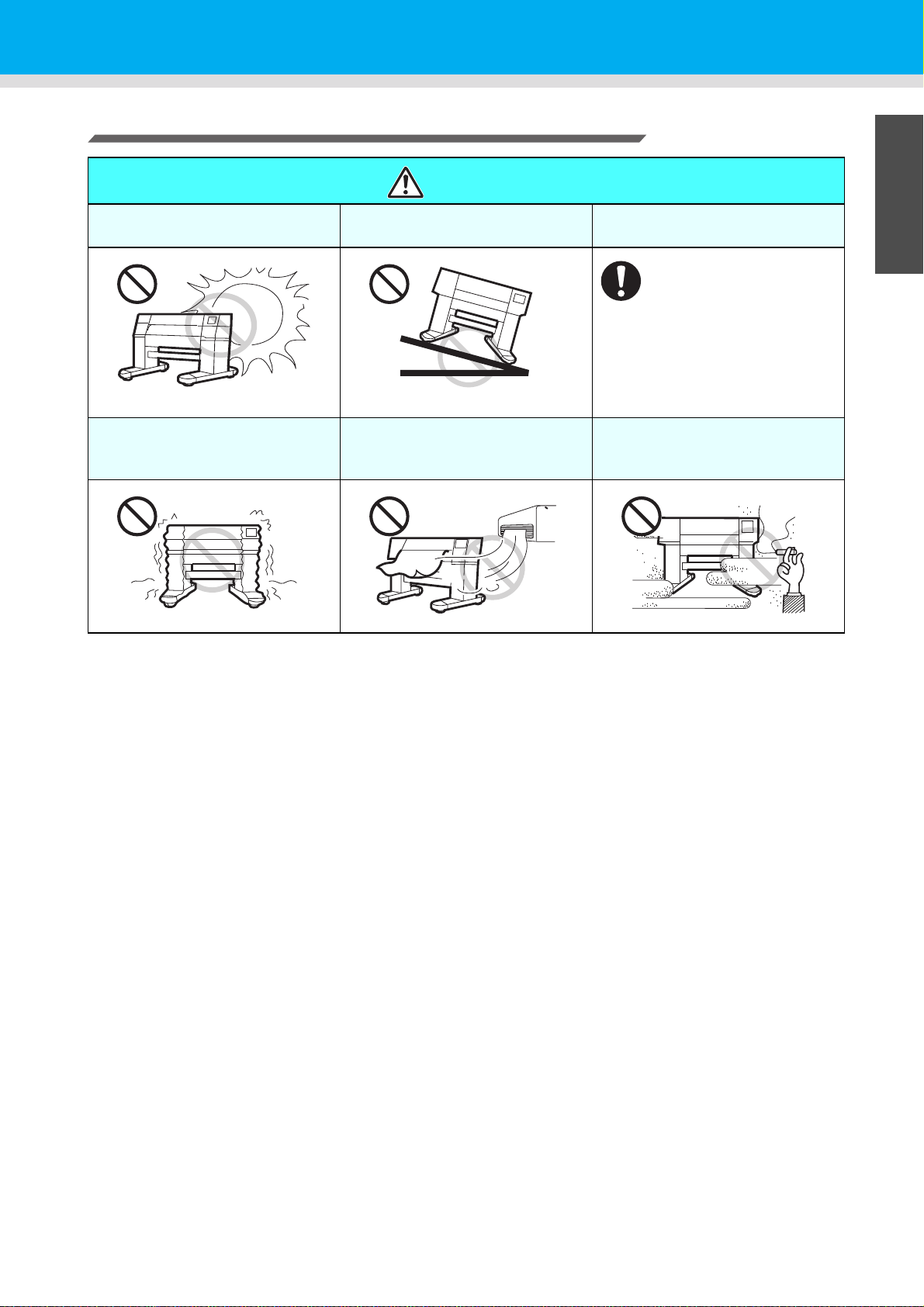
Cautions on Installation
Safety Precautions
CAUTION
A place exposed to direct
sunlight
A place that vibrates
On an inclined surface
A place exposed to direct air
flow from an air conditioner or
the like.
A place where temperature or
humidity varies significantly
• Use the machine under the
following environmental
conditions:
• Operating environment:
20 to 30 °C
(68 to 95 °F)
35 to 65 % (Rh)
1
Around a place where fire is
used
2
3
4
5
xiv
6
Page 16
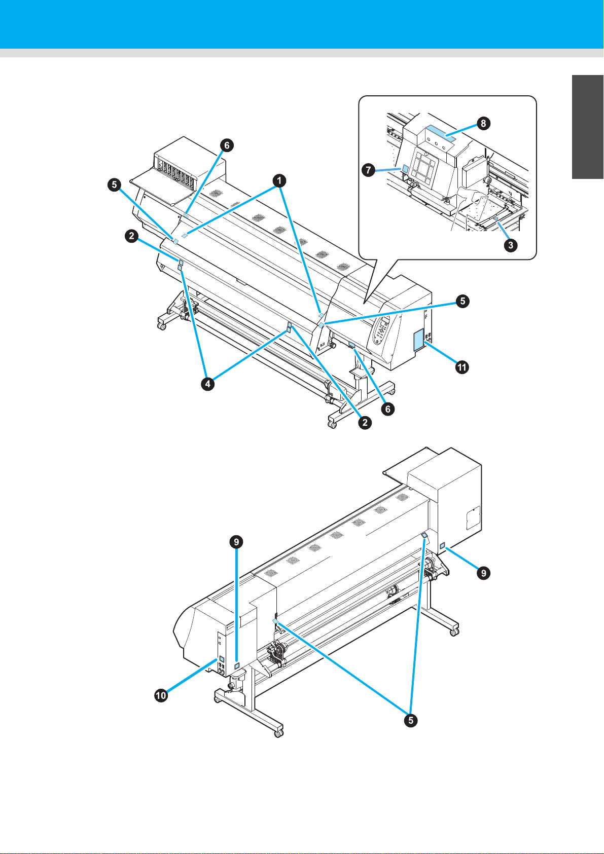
Safety Precautions
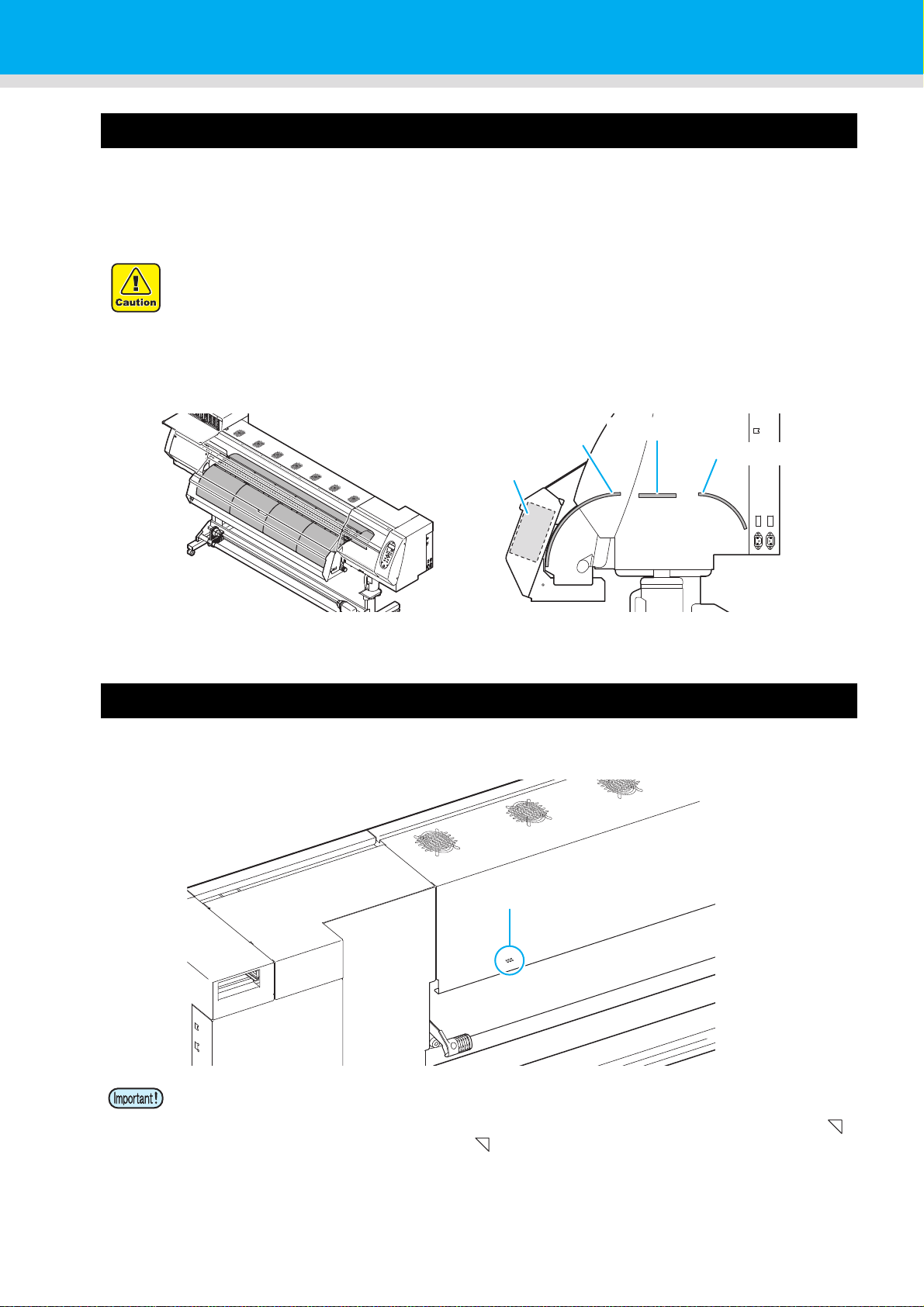
Safety interlock
This machine is equipped with interlocks to terminate the operation for your safety when the cover opens
during printing etc. (red circle parts in the figure below).
xv
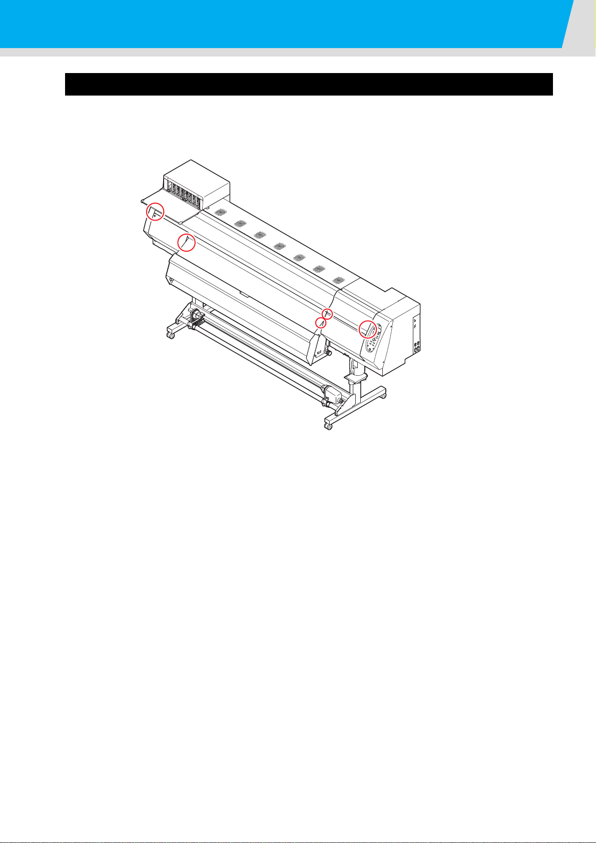
Page 17
Warning labels
When the front cover is open
Stuck on right and left media
press
Warning labels are stuck on the machine. Be sure to fully understand the warning given on the labels.
1
2
3
4
xvi
5
6
Page 18
No.
2
5
5234
7
8
78
9
-
10
910
CAN ICES-3 (A)/NMB-3(A)C AN I CE S -3 (A )/ N MB -3 (A )
COLORC O LO R INKJETI N KJ E T PRINTERP R IN T E R
Pro L4130P ro L 4 13 0
PLUG1P LU G1 100-240V1 00 -2 40 V ~,~ , 12A-8A,1 2A -8 A, 50/60Hz,5 0/ 60 H z, forf or powerpo we r suppliessu pp l ie s heaterh ea te r
PLUG2P LU G2 100-120V/220-240V1 00 -1 20 V /2 20 -2 40 V ~,~ , 12A/8A,1 2A /8 A, 50/60Hz,5 0/ 60 H z, forf or hetaershe ta er s
weightwe ig h t ofo f machinem ac hi ne 235kg23 5 kg
RICOHR I C OH COMPANY,C O MP A N Y, LTDL T D
3-63 -6 NakamagomeN a ka m a go m e 1-chome,1- c h om e , Ohtaku,O h t ak u , Tokyo,T ok y o , 143-85551 4 3 -8 5 5 5 JapanJ ap a n
IntertekI n t e r t e k
CAN ICES-3 (A)/NMB-3(A)C AN I CE S -3 (A )/ N MB -3 (A )
COLORC O LO R INKJETI N KJ E T PRINTERP R IN T E R
Pro L4160P ro L 4 16 0
PLUG1P LU G1 100-240V1 00 -2 40 V ~,~ , 12A-8A,1 2A -8 A, 50/60Hz,5 0/ 60 H z, forf or powerpo we r suppliessu pp l ie s heaterh ea te r
PLUG2P LU G2 100-120V/220-240V1 00 -1 20 V /2 20 -2 40 V ~,~ , 12A/8A,1 2A /8 A, 50/60Hz,5 0/ 60 H z, forf or hetaershe ta er s
weightwe ig h t ofo f machinem ac hi ne 235kg23 5 kg
RICOHR I C OH COMPANY,C O MP A N Y, LTDL T D
3-63 -6 NakamagomeN a ka m a go m e 1-chome,1- c h om e , Ohtaku,O h t ak u , Tokyo,T ok y o , 143-85551 4 3 -8 5 5 5 JapanJ ap a n
IntertekI n t e r t e k
1
6
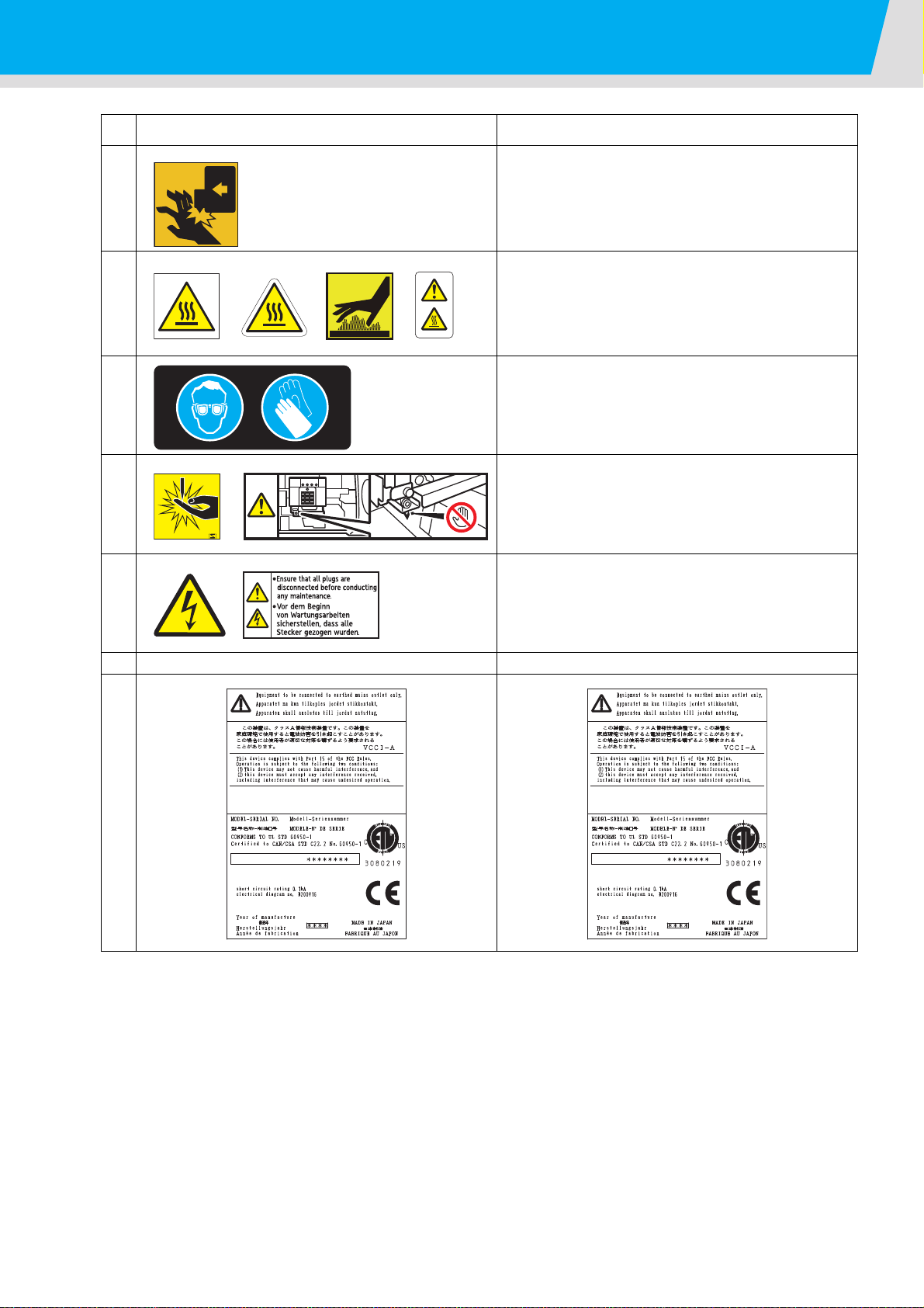
Warning labels
Always follow the procedure described in this manual
when loading and replacing paper, removing jammed
paper, cleaning the media transfer surface, and performing any other operations inside the machine. Otherwise, the carriage may hit or catch your hand and
cause injury.
There are hot surfaces inside the machine. Do not
touch any parts other than the ones described in this
manual when removing jammed paper. Otherwise,
burn injury may result.
Always wear the goggle and gloves provided with this
machine to prevent your skin to come in contact with
the cleaning fluid when cleaning the ink station and
print head.
There is a cutter inside the machine for cutting print
media. Do not touch any parts other than the ones
described in this manual when loading and replacing
paper, removing jammed paper, and cleaning the
media transfer surface.
11
Electrical power is supplied to this machine via multiple power cables. To completely disconnect all supply
of power to the machine, all power cables?must be
disconnected..
(Pro L4130) (Pro L4160)
xvii
Page 19

Chapter 1
Before Use
This chapter
describes the items required to understand before use, such as the name of each part of
the machine or the installation procedures.
Moving This Machine ....................................1-2
Where to Install This Machine ..................... 1-2
Working Environmental Temperature ......... 1-2
Moving This Machine .................................. 1-2
Names of Parts and Functions ......................1-3
Front Side of the Machine ........................... 1-3
Rear Side and Right Side of the Machine ... 1-4
Operation Panel .......................................... 1-5
Signs on the power switch .......................... 1-5
Heater ......................................................... 1-6
Media sensor ............................................... 1-6
Carriage ...................................................... 1-7
Cutter blade and slot for cutting .................. 1-7
Connector of Temperature sensor/
Drying heater/ Take-up device .................... 1-8
Capping station ........................................... 1-8
Pinch rollers and Feed rollers ..................... 1-9
Connecting Cables ......................................1-10
Connecting USB2.0 Interface Cable ..........1-10
Connecting the power cable ......................1-11
Inserting ink cartridge ..................................1-12
How to assemble ink cartridge ...................1-12
About the ink that can be used with this
machine .....................................................1-14
Setting orders of ink cartridges ..................1-15
Caution in handling of ink cartridges ..........1-17
Media ..........................................................1-18
Usable sizes of media ................................1-18
Caution in handling of medias ...................1-18
About antistatic sheet ..................................1-19
Page 20
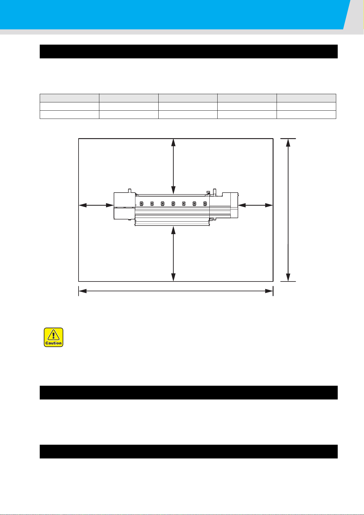
Moving This Machine
Pro L4130: 3634 mm or more
Pro L4160: 3879 mm or more
500 mm
or more
500 mm
or more
1000 mm or more
1000 mm or more
2854 mm
or more
Where to Install This Machine
Secure a suitable installation space before assembling this machine.
The place of installation must have enough space for not only this machine itself, but also for the printing
operation.
Model Width Depth Height Gross weight
Pro L4130 2634mm 854mm 1435mm 216kg
Pro L4160 2879mm 854mm 1435mm 231kg
• When you usually use photographic fixer, do not install this machine in a room filled with
vapor of photographic fixer. If you install this machine in such a room, ink adhering to the
head hardens and it may cause image quality defect that cannot be improved even if you
perform head cleaning many times and may cause nozzle clogging.
• Besides photographic fixer, if you leave this machine in an environment where acidic vapor
(acetic acid, muriatic acid, etc.) is generated, the same phenomenon occurs.
Working Environmental Temperature
Use this machine in an environment of 20 to 30°C to ensure reliable printing.
The heater temperature may not reach the set value, depending on the ambient temperature.
Moving This Machine
Consult our service office in your area before moving this machine.
1-2
Page 21
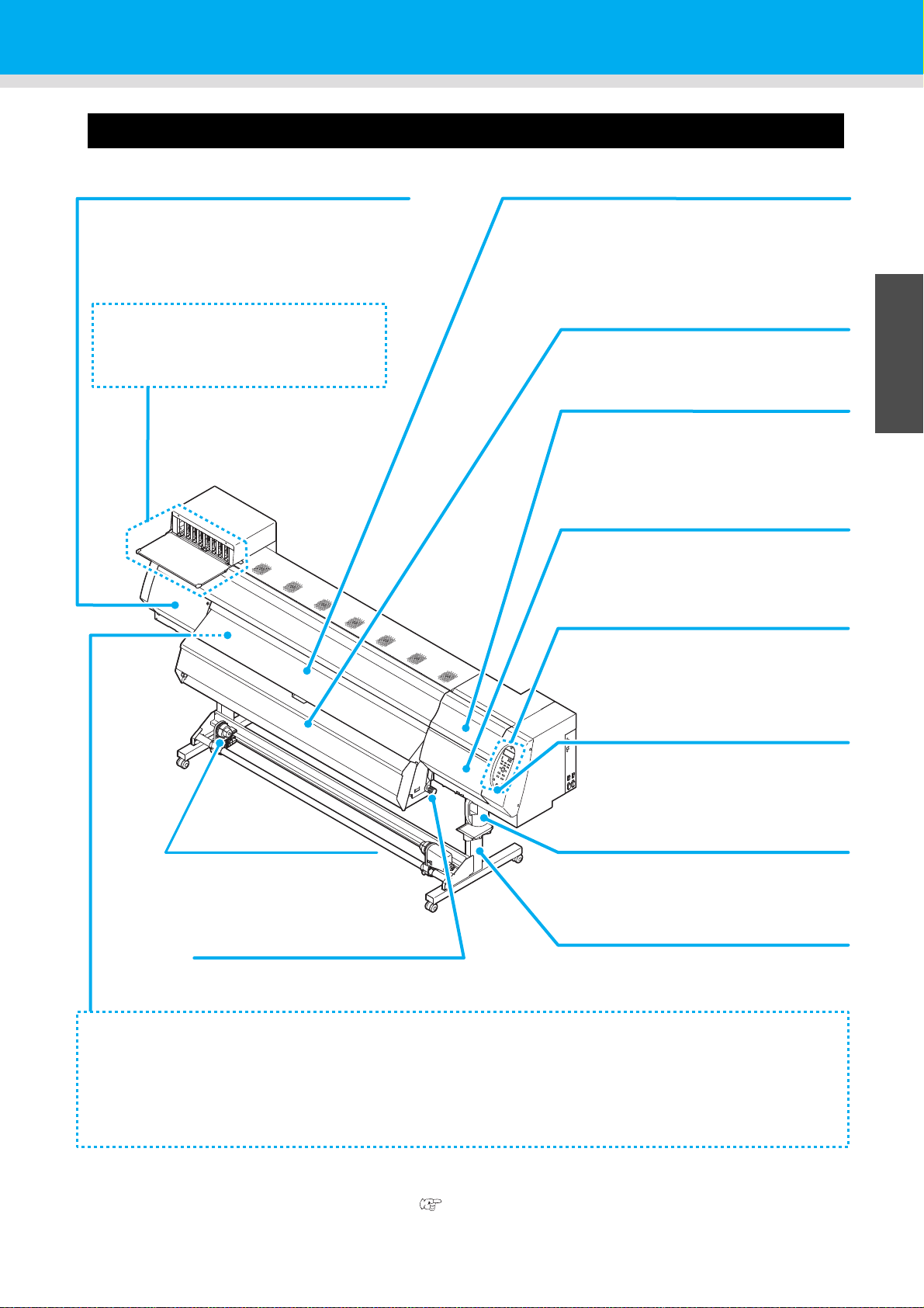
Names of Parts and Functions
Front cover
Open the cover in setting of medias, taking of measures
against jamming of medias or in maintenance inside the
station.
Even when the power switch is off, keep this cover and
the other covers closed.
Operation panel
This panel has the operation keys required for
operating the machine and the LCDs for
displaying setting items, etc.
Clamp lever (front)
Moves the pinch rollers up and down to hold or
release the media.
Power switch
*1
Turns on/off the power to the machine.
Waste ink bottle
Waste ink gathers in this bottle.
Stand
Supports the main body of the machine. It is
provided with casters that are used to move
this machine.
Left maintenance cover
Open the cover in maintenance.
Even when the power switch is off, keep all covers
closed.
Media Transfer Surface
Print media is retained and transferred along the media transfer surface by vacuum. Three heaters are installed inside
the media transfer surface.
Print heater/ Post-heater
Fixes and dries the ink on the currently produced print. (Located inside the Media Transfer Surface)
Electrostatic sheet
Prevents the media from sticking to the Media Transfer Surface due to static.
Ink cartridge setting section
Set the ink cartridge for each color.
*1 : The power switch under the operation panel lights in green when the power is turned on. The ink clogging
prevention function is periodically operated even when the power switch is OFF if the main power switch
keeps being ON. (Auto maintenance function) P.1-4
Take-up device
Take up the output drawn with a
roll medium automatically.
Drying heater
The dryer blows warm air on the
printed paper to fix and dry ink.
Maintenance cover (upper right)
Open this cover when performing
maintenance on the print head and the
surrounding parts.
Maintenance cover (lower right)
Open this cover when performing
maintenance on the print head and the
surrounding parts.
Front Side of the Machine
1
Before Use
3
4
5
6
1-3
Page 22
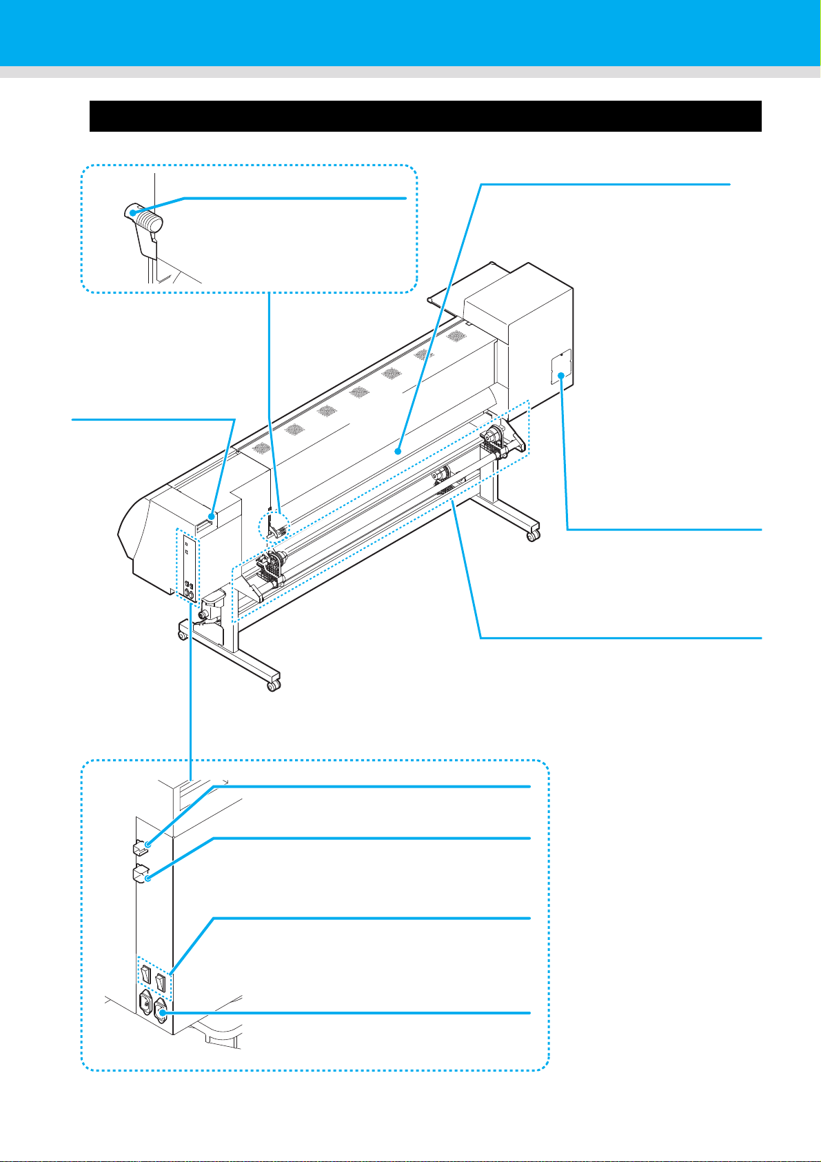
Rear Side and Right Side of the Machine
Pre-heater
Preheats the media before printing.
(Located inside the Media Transfer
Surface)
AC inlet
Connect the power cable to the AC inlet.
Clamp lever (rear)
Interlocks with the clamp lever in the
font of this machine.
LAN connector
Do not use this LAN port. It is for use by the
qualified service technicians only.
Main power switch
Turns on/off the main power for this machine.
Leave the main power turned on to prevent ink
clogging.
Cleaning solution cartridge
Set a Washings cartridge
that is recommended
by this company.
Roll holders
Putting this into the paper core (right and left) of
a narrow roll medium (less than 1.6m), hold the
medium. It supports the paper core of 2 inch
and 3 inch.
USB 2.0 connector
This is USB2.0 interface connector.
W filter maintenance cover
Cover for white filter
maintenance.
1-4
Page 23
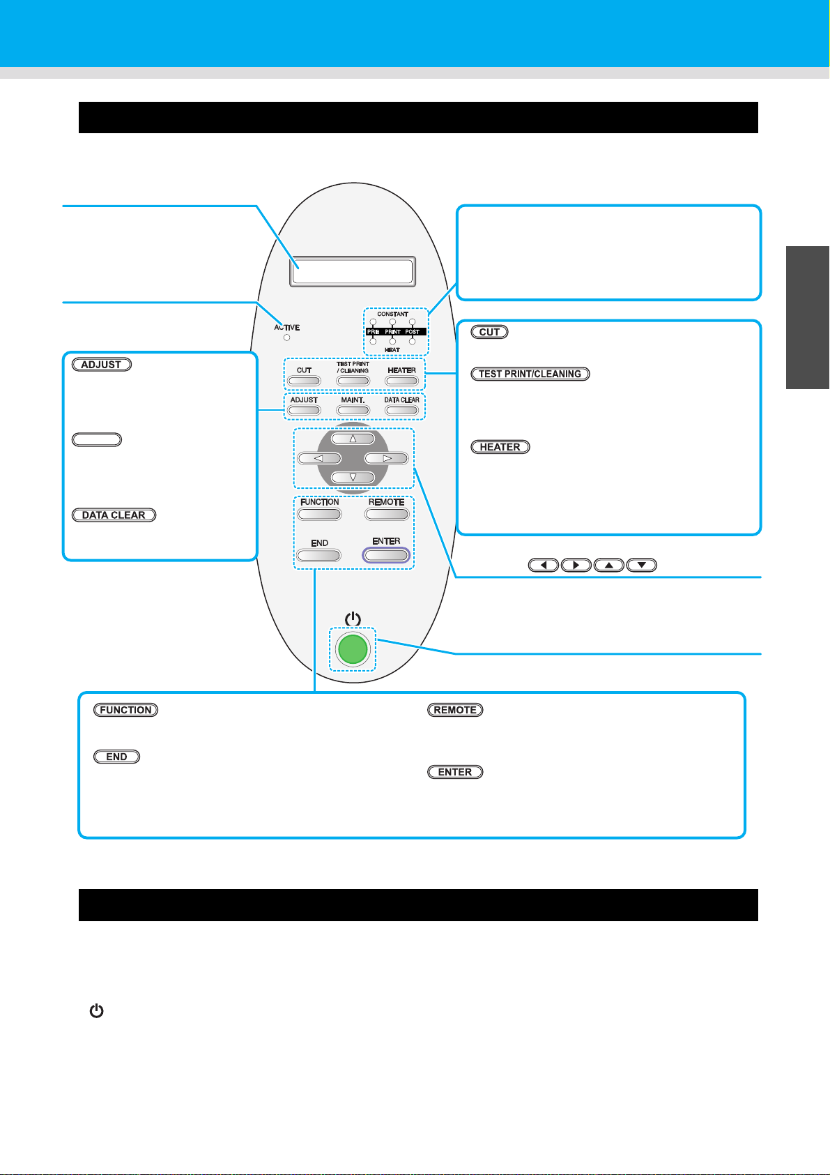
Names of Parts and Functions
JOG key
Use these keys to shift the carriage or the media in
[LOCAL]. Also use them to select an item of printing
conditions.
key
Use this key to display function setting menu.
key
Cancels the last input value or returns the setting menu
to the immediate higher level of the hierarchy.
Display
Displays the status of the
machine, set items and errors.
ACTIVE lamp
It lights when the power
supply is turned on.
key
Use this key to switch between [REMOTE] and
[LOCAL].
key
Registers the last input value as the setting value or
goes to the immediate lower level of the hierarchy.
key
Use this key on cutting .
key
Draws test patterns to check if there are any
drawing failures such as ink clogging.
Or executes Head cleaning at ink clogging.
key
Use this key to set the temperatures of the Preheater, Print heater, Post-heater and Drying heater
or check the current temperature of the Media
Transfer Surface.
key
Performs the adjusting function
such as “Drop.POScorrect” and
“Feed COMP.”
key
Performs the maintenance
function such as station
maintenance.
key
Deletes the data that have been
received.
MAINT.
CONSTANT lamp
Lights in green when the heater temperature
reaches the set temperature.
HEAT lamp
Lights in orange during heating up of the heater.
Power switch
Turns on/off the power to the machine.
Operation Panel
Use the operation panel to make settings for printing or operate this machine.
1
Before Use
Signs on the power switch
3
4
The meaning of the signs on the machine's power switch are as follows:
・|:Power is on
・○:Power is off
・:Standby
5
6
1-5
Page 24
Heater
Post-heater
Print heater
Drying-heater
Pre-heater
Media sensor
Pre-heater/Print heater/Post-heater are equipped on the Media Transfer Surface.
The Pre-heater is used for pre-heating of the media prior to printing to prevent rapid changes in temperature.
The Print-heater improves the image quality in printing.The Post-heater and drying-heater dries ink after
printing.
• While the heater is on, the Media Transfer Surface is very hot.When the front cover is to be
opened or media is to be replaced, lower the heater temperatures and wait until the Media
Transfer Surface temperature drops;otherwise, you can get burned.
• When the media is to be replaced with a thin one, lower the heater temperatures and wait until
the Media Transfer Surface temperature drops adequately.Setting a thin sheet of media while
the Media Transfer Surface is hot may cause the media to stick to the Media Transfer Surface
or cause wrinkling or curling of the media.
Media sensor
The media sensor detects the presence of the media and the media length.
This machine has a media sensors on the Media Transfer Surface (in the rear).
• When setting a medium, be sure to cover the medium sensors located on the rear of the Media
Transfer Surface. The media cannot be detected unless it is placed over the sensor.
• In case that you use 210mm-wide media, media cannot be detected if it is set in accordance with .
Set media approximately 15mm inner than .
1-6
Page 25
Carriage
Carriage
Cutter unit
slot for cutting
Cutter blade
The carriage is provided with the heads for printing, the cutter unit
for cutting off the sheet of media, etc.
A lever is also provided to adjust the height of Head in 3 stages
according to the thickness of media. ( P.2-5)
Names of Parts and Functions
1
Cutter blade and slot for cutting
The carriage is provided with a cutter unit for cutting off the media that has been printed on.
The cutter cuts off the sheet of media along the slot for cutting on the Media Transfer Surface.
The cutter blade is consumables. If it gets dull, replace it with new one. (P.4-32)
• The blade is sharp. Be careful not to hurt yourself or anyone else.
Before Use
3
4
5
6
1-7
Page 26
Connector of Temperature sensor/ Drying heater/ Take-up device
Drying heater (blue)
Temperature sensor (red)
Take-up device (black)
Connector of Temperature sensor/ Drying heater/ Take-up device
If an error related to the Temperature sensor/ Drying heater/ Take-up device occurs, refer to the Chapter 5 and
check the connector.
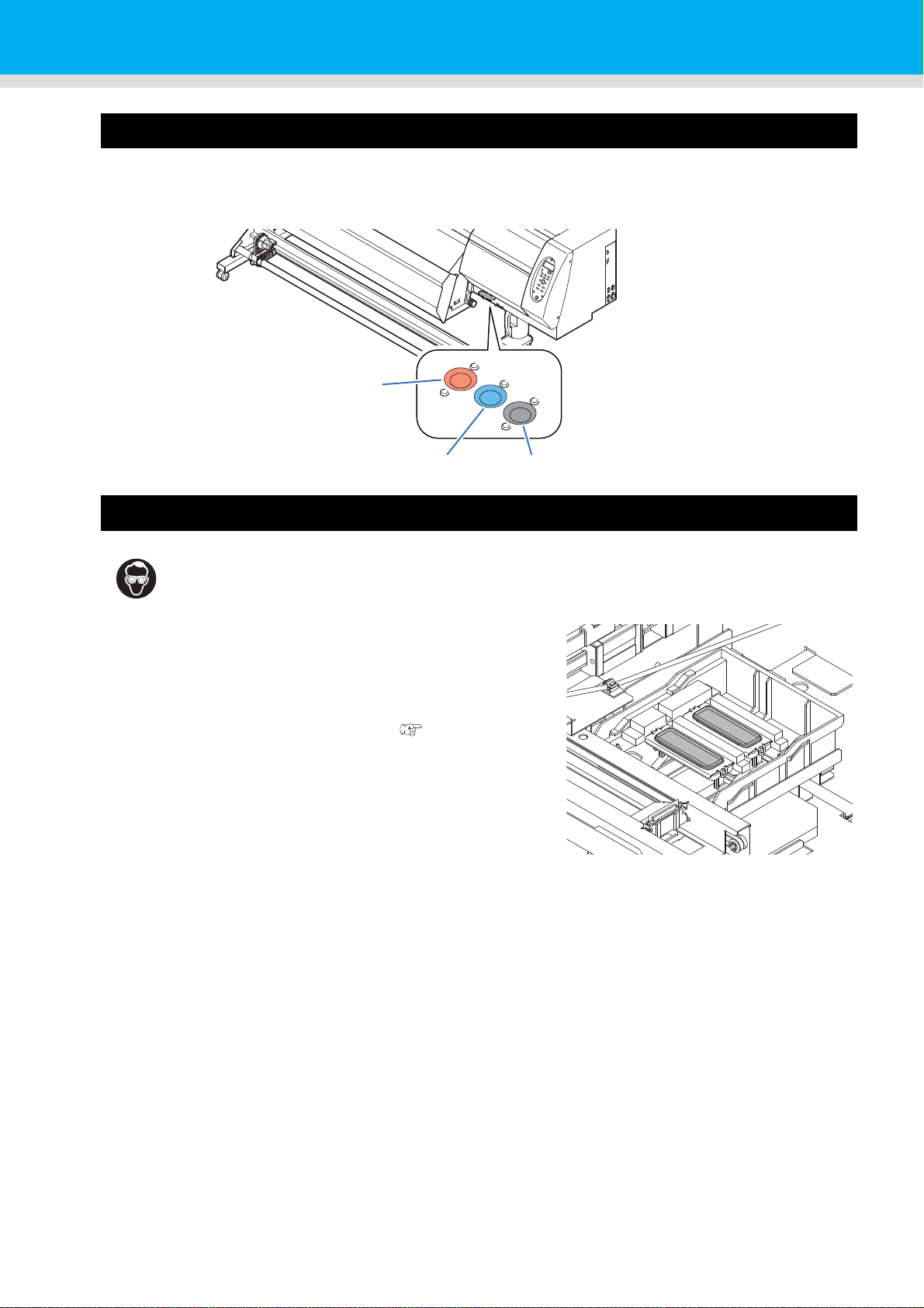
Capping station
• Be sure to wear the attached goggles in cleaning within the capping station to protect your
eyes against ink. Otherwise, you may get ink in your eyes.
The capping station consists of the ink caps, the wiper for cleaning
the heads, etc.
The ink caps prevent the nozzles in the heads from drying up.
The wiper cleans the nozzles in the heads.
The wiper is consumable.If the wiper is deformed or the media is
stained, replace the wiper with a new one. ( P.4-28)
1-8
Page 27
Names of Parts and Functions
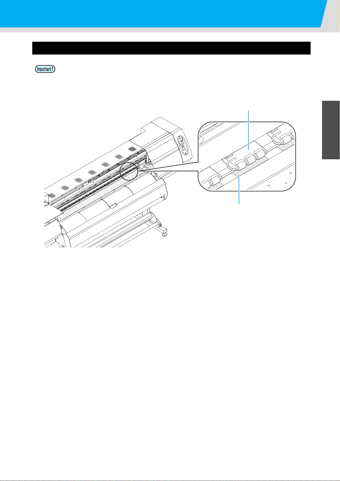
Feed roller
Pinch roller
Pinch rollers and Feed rollers
• Keep the pinch rollers lifted up when this machine is not in use. If the pinch rollers are left lowered for
an extended period of time, they can be deformed and fail to securely retain the media.
This machine retains the media with the pinch rollers and feed rollers. During printing operation, the feed rollers
feed the media forward.
1
Before Use
3
4
5
6
1-9
Page 28
Connecting Cables
USB cable
USB 2.0 repeater cable
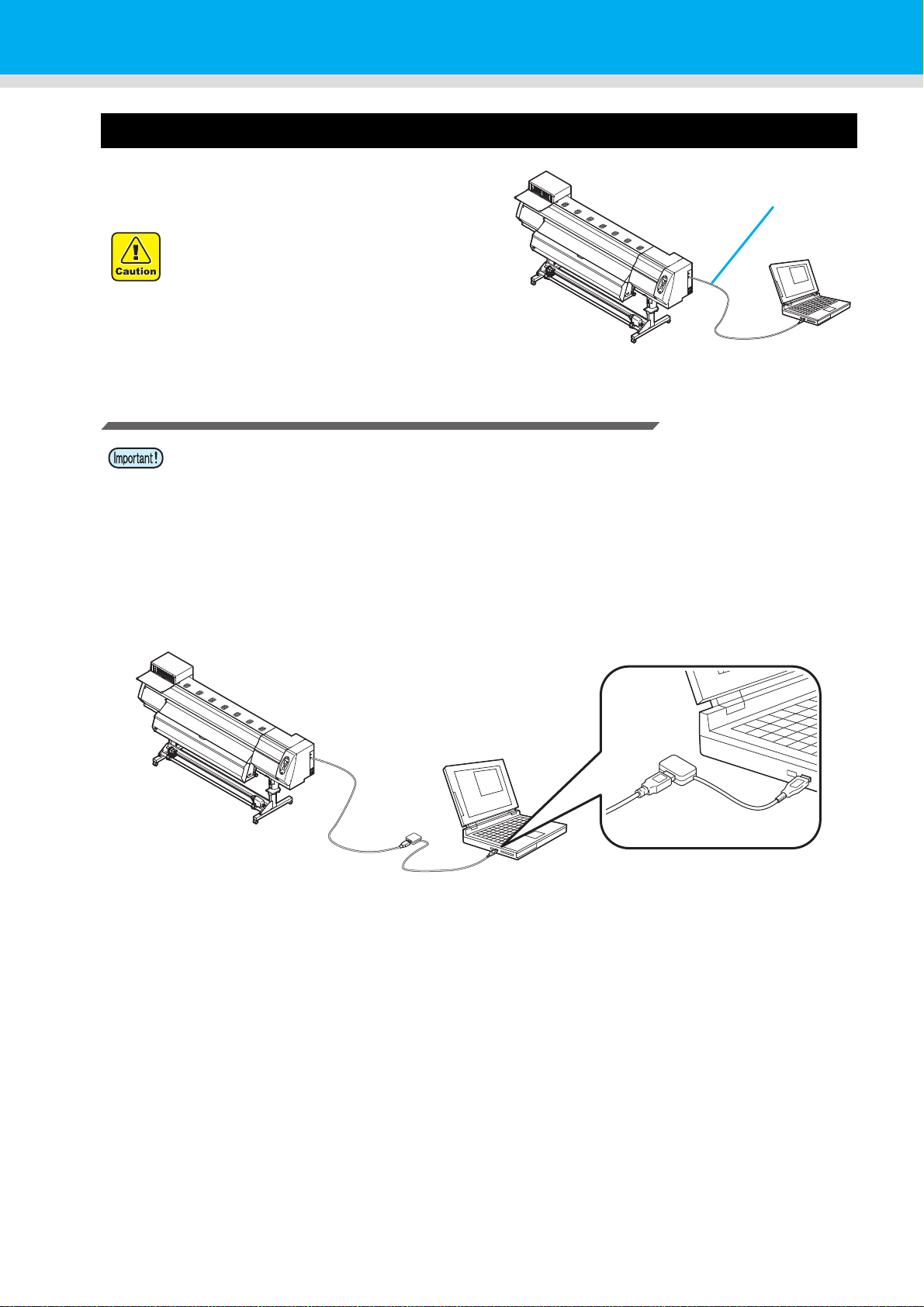
Connecting USB2.0 Interface Cable
Connect the PC and this machine with the USB2.0
interface cable.
• Your RIP must be compatible with USB
2.0.
• When you connect USB cable, do not
touch the connector contact point with
your bare hand. Static may be generated
and it may break the PCB of this machine.
Notes on USB 2.0 Interface
• Your RIP must be compatible with USB 2.0.
z When two or more Pro L4160/L4130 machines are connected to one personal computer
When two or more Pro L4160/L4130 machines are connected to one personal computer, the personal
computer may not recognize all the Pro L4160/L4130 machines normally.
Reconnect the unrecognized Pro L4160/L4130 machine to another USB port, if available, and check to see if it
is recognized.If the Pro L4160/L4130 machine is not recognized by the newly connected USB port, use USB
2.0 repeater cables available on the market.
z Notes on peripheral devices in USB high speed mode
When a peripheral device (USB memory or USB HDD) to be operated in USB high speed mode is connected to
the same personal computer that a Pro L4160/L4130 machine is connected to, the USB device may not be
recognized.
When Pro L4160/L4130 is connected to the personal computer to which an external HDD is connected via
USB, the speed of data output to Pro L4160/L4130 may drop.That can cause the head unit to stop temporarily
at the right or left end during printing.
1-10
Page 29
Connecting Cables
Inlet 1 Power cable
Cable band
Inlet 2
Power plug
Socket
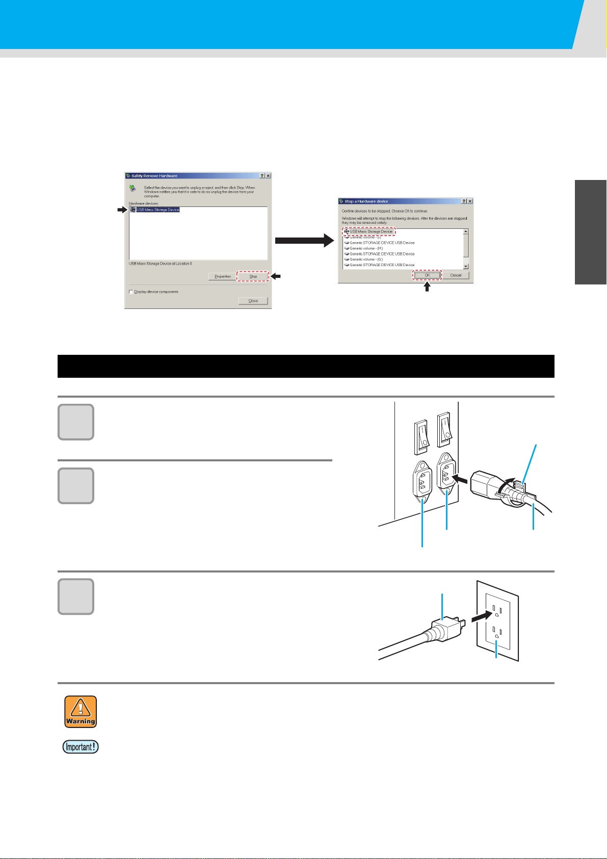
z Removing USB memory
If a USB memory module is inserted in the personal computer to which a Pro L4160/L4130 machine is
connected, click "Stop" in the "Safely Remove Hardware" window by following the instructions given there first
and then remove the module.
Leaving a USB memory module inserted can cause [ERROR 201 COMMAND ERROR].
Copy the data onto the hard disk before outputting it for printing.
1
Before Use
Connecting the power cable
Insert the power cable into an inlet of the
1
2
machine.
Secure a cable band.
• Secure the cable with the cable band attached to this
machine.
Insert the power plug into a plug socket.
3
3
4
• Do not use any power cables other than the attached power cable.
• For Inlet 1 and 2, be sure to supply power from the outlet of the same voltage.
• Be sure to connect the power cable to the outlet near this machine, and make sure that the power
cable can be easily removed.
• Connect the power cable to the grounded outlet.Otherwise, it may result in fire or an electric shock.
• Check the voltage of the wall outlet and the capacity of the circuit breaker before you plug the power cords.
Plug each power cord to different outlet that has independent circuit breaker. If you plug more than one
power cord to wall outlets that share the same circuit breaker, the power may be cut off by the breaker.
5
6
1-11
Page 30
Inserting ink cartridge
Press the center part with your finger.
Raise.
Insert an ink cartridges.
How to assemble ink cartridge
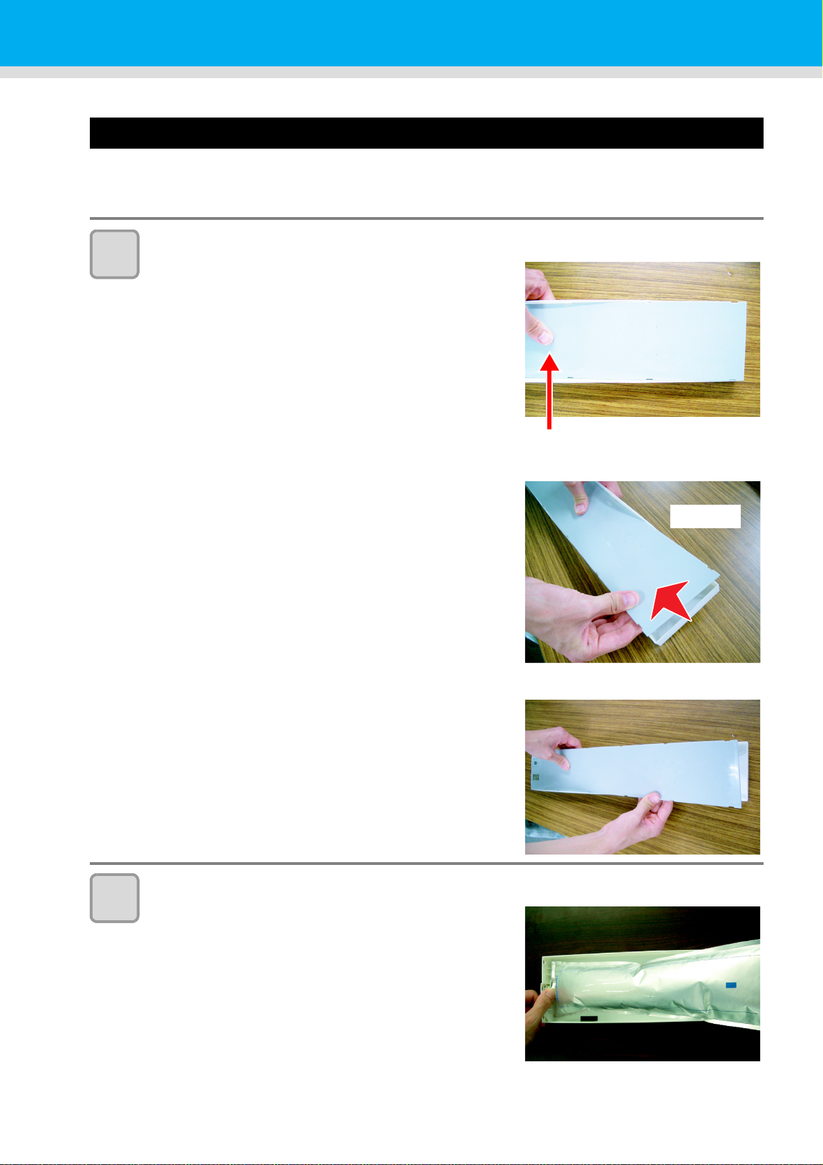
Before setting the ink cartridge, it is required to set the ink pack on the eco cartridge.
By following the next procedures, assemble the ink cartridge.
Open the cover of the eco cartridge.
1
(1) Press the center part of the cover with your finger.
• The claw on the side without attaching part of IC chip
comes off.
2
(2) Raise the cover as described in the photo.
• At this time, the claw on the IC chip side does not
come off.
Do not raise the cover forcedly so that you may not
damage the claw.
(3) Remove the remaining claw while pressing the cover
as indicated in the photo, and remove the cover.
Set the ink pack on the eco case.
(1) Turn the side with double coated tape downward and
insert the stopper.
• After inserting the stopper, push it firmly with your
finger.
1-12
Page 31

3
Good example
The corner of the case
matches the ink pack
corner.
The ink pack has
gone too far
downward.
The ink pack goes slack in
spots.
Bad example
No gap shall be found.
There is a gap.
The ins and the outs is
reverse.
The back and the forth is
reverse.
Inserting ink cartridge
(2) Peel the seal of double coated tape.
Firmly fix the ink pack on the eco case with
double coated tape so that it may not move.
• Fix the ink pack after pulling it so that the ink pack may not
go slack.
1
Before Use
• Fix the ink pack so that it may not be biased in the eco case.
4
5
Attach the cover.
• Hang the claw on the IC ship side and then insert the cover
into the case.
Attach the IC chip.
• Attach the IC chip as indicated in the photo.
• Attach it so that there is no gap in the part indicated with an
arrow.
Bad example of attaching IC chip
3
4
5
6
1-13
Page 32

About the ink that can be used with this machine
SHAKE WH I TE I NK
CARTRIDGES [ ENT ]
A part
(the place to stick a needle)
B part
(the slot on the bottom)
Cover with paper towel firmly
and shake ink slowly
Repeat this
A part
The following three types of ink sets can be used with this machine: 4 color, 6 color, and 6 color+white versions
• 4-color version: 2 each of Cyan, Magenta, Yellow and Black ink cartridges are used.
• 6-color version: 1 each of Yellow, Orange, Green, and Black, 2 each of Cyan and Magenta ink cartridges are
used.
• 6-color+white version: 1 each of Cyan, Magenta, Yellow, Orange, Green and Black, and 2 White ink
cartridges are used.
White ink is fed from an ink cartridge, but the inks for Cyan, Magenta, Yellow, Orange, Green and Black are
supplied from an ink-pack. Set the inks in the eco case before you set the ink cartridge. Also, the white ink is
contained in a eco cartridge that is shorter in length than the cartridge of Cyan, Magenta, Yellow, Orange,
Green and Black inks.
Slowly shake the white ink cartridge more than twenty times right and left.
1
• To prevent ink from leaking when you shake the Eco-cartridge, wear gloves and firmly cover the A part
of the upper surface of the cartridge and the B part of the bottom surface of the Eco-cartridge with paper
towels. Then, shake it more than twenty times right and left so that ink flows inside the cartridge.
• If you shake it too strong, the pack inside may be damaged and it may cause ink
leakage. Therefore, perform this carefully.
• If the remaining amount of ink is less, ink in the Eco-cartridge cannot be beaten enough.
Tilt the cartridge until it becomes vertical.
• When you use white ink:
When 24 hours have passed with the power supply
is ON, or, when the power supply is ON, the
message is displayed.
As the component of white ink is easy to settle out, it is necessary to shake it
periodically.
1-14
Page 33

2
The front side
4 colors model M
M
C
C
YYKK
6 colors model Inks M M C C Or G Y K
6 colors+W model MOrC G Y K WW
Inserting ink cartridge
Insert the ink cartridge.
• Insert the ink cartridge lengthwise with the surface having
IC chips pointing to the left side.
Setting orders of ink cartridges
The orders of ink cartridges set in the ink station differ depending on the ink set you use.
• Set the ink cartridge according to the cartridge label under the ink station.
1
Before Use
3
4
5
6
1-15
Page 34

Changing an ink cartridge
Ink cartridge lamps
Perform as follows when [INK END] or [INK NEAR END] is displayed on the display.
z When [INK END] is displayed
(1) Pull out an ink cartridge to be replaced.
(2) Insert a new ink cartridge, paying attention to the direction of IC chip.
z When [INK NEAR END] is displayed
There is a little of ink left. It is recommended to replace the ink cartridge soon since ink may become empty in
printing while printing is continuously enabled.
When you press the key in LOCAL, you can check the Eco-cartridge to be replaced in the local
guidance.
( P.3-21)
• When you changed the ink pack, be sure to change the IC chip, too.
For Ink cartridge lamps
The condition of the ink cartridges set in the machine is confirmable with lamps located over the ink cartridges.
Condition of Lamp Description
No error
There is less ink in the ink cartridge (Near
End), or ink has expired. It will become
unusable soon.
There is no ink in the ink cartridge, or the ink
cartridge cannot be used due to other ink
error. ( P.5-5)
As ink has expired, the ink cartridge cannot
be used.
No error
Indicates that ink is supplied.
When you use four-color ink set, this
machine first supplies ink from the ink
cartridge whose ink expires soon.
Upper row
Red lamp
Lower row
Green lamp
OFF
Blinking
ON
Quick
blinking
OFF
ON
About ink expiration date
The ink cartridge has its expiration date.
You can use the Eco-cartridge in two months after the expiration date indicated on it, however, you cannot use
it when three months have passed from the expiration date.
As LED will blink quickly to inform you of it, replace the Eco-cartridge.
Ex.) When the expiration date is April 2014
May 2014: Usable
June 2014: Usable (LED blinks)
July 2014: Unusable (LED blinks quickly)
About cartridge ink end and ink near end
When ink near end (less ink) occurs, LED “red” blinks to inform you of it. It is recommended to replace it as
soon as possible.
When ink end (no ink) occurs, LED “red” is lit to inform you of it. Replace the ink cartridge.
1-16
Page 35

Caution in handling of ink cartridges
• If you get ink in your eyes, immediately wash your eyes with a lot of clean running water for at
least 15 minutes. In doing so, also wash the eyess to rinse ink away completely. Then, consult
a doctor as soon as possible.
• Depending on how the machine is used, the [INK END] message may be displayed even if the
[INK NEAR END] message is not yet displayed. The remaining amount of ink in a cartridge is
calculated based on the printed data and the estimated amount of ink used by maintenance
processes, and may not show the actual amount of ink in the cartridge.
• Use genuine ink cartridges for this machine. This machine functions by recognizing the
genuine ink cartridges. In case of troubles caused by modified ink cartridges or the like, it shall
be out of the warranty even within the warranty period.
• If the ink cartridge is moved from a cold place to a warm place, leave it in the room temperature
for three hours or more before using it.
• Make sure to store ink cartridges in a cool and dark place.
• Store ink cartridges and waste ink bottle in a place that is out of the reach of children.
• Request an industrial waste processor for processing of the ink cartridges that are no longer
required.
• Do not shake ink cartridges violently. This may result in ink leakage from the Eco-cartridges.
• Do not refill the ink in the ink-pack and white ink cartridge. This may result in troubles.
RICOH will not bear any responsibility for any damage caused by the use of the ink cartridges
refilled with ink.
• Do not touch or stain the contacts of the ink cartridge. This may cause damages on printed
circuit boards.
• Do not disassemble the white ink cartridge.
Inserting ink cartridge
1
Before Use
3
4
5
1-17
6
Page 36
Media
Usable media sizes and notes for handling are described.
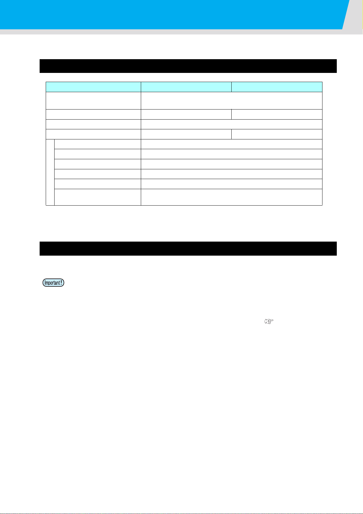
Usable sizes of media
Model Pro L4130 Pro L4160
Type of Recommended media
Maximum width
Minimum width
Maximum printing width
Thickness 0.3mm or less
Roll outside diameter
Roll weight
Roll inside diameter 3 or 2 inches
Side printed Side facing outward
Roll media
Roll end treatment
Thin coat paper/PET/Tarpaulin/Weatherproof PVC/Polyester cloth/
Cotton
1371mm 1620mm
210mm
1361mm 1610mm
φ180mm and less
25kg and less (for small-size media holder, 25kg and less)
The roll end is gently fixed to the core with weak-adhesive tape or weak
glue for easy removal.
*1
*1. Some media have bad drying characteristics. Please check this beforehand.
Caution in handling of medias
Pay attention to the followings for handling of medias.
• When handling media, wear the gloves.
If you touch the media with your bare hand, the media may be stained due to fingerprints or oil of your
finger. Be careful about it.
• Do not leave the media with the heater ON for a long time.
Waviness may occur on the media and it may cause media clogging.
When the pinch roller is at the lower position, even if it is for a short time, impression produced by the
pinch roller is left depending on the media material. Perform test feeding
media status.
• Use media recommended by RIOCH to ensure reliable, high-quality printing.
Set the heater temperature to meet the characteristics of the media.
• Set the temperature of the Pre-heater, Print heater and Post-heater according to the type and
characteristics of the media used.
Automatic temperature setting can be made on the operation panel by setting the profile on the
dedicated RIP. For setting on the RIP, refer to the instruction manual for your RIP.
• Pay attention to the expansion and contraction of the media.
Do not use media immediately after unpacking. The media can be affected by the room temperature
and humidity, and thus it may expand and contract.
The media have to be left in the atmosphere in which they are to be used for 30 minutes or more after
unpacked.
• Do not use curled media.
This may result in paper jamming.
If a regular-sized coated sheet of media is rolled and stored, the coated side has to face outside.
• Be careful to dusts on the edge face of the medium.
Some rolls have dusts contained in the package gathered on the edge surface of the roll. If you use as
it is, the drawing quality may be degraded due to nozzle missing or ink drops. Be sure to set the roll
after removing dusts adhering on the edge face of the roll.
• Use a media wider than 450 mm when performing the ink drop position correction for bidirectional
printing. Correcting the ink drop position for bidirectional printing cannot be performed on narrower
media. Use unidirectional printing in such a case. Also, select [STRONG] in the [VACUUM] setting if the
media is not securely adhered to the media transfer surface when using a media such as narrow media.
(P.2-19) to check the
1-18
Page 37

About antistatic sheet
Sheet
spring
Pro L4130: three antistatic sheets, Pro L4160: four antistatic sheets are attached in this machine.
The electrostatic sheet is used to prevent the media from clinging due to static.
Use this when static or deflection of the media on the post heater occurs and affects the media feeding.
z Fix the electrostatic sheet
Hang the claw of the antistatic sheet on the groove of the Media Transfer Surface.
1
Before Use
z Remove the electrostatic sheet
Remove it in the reverse procedures of assembling, and use with it hanging on the attached sheet spring.
3
4
5
6
1-19
Page 38

About antistatic sheet
Sheet
holder
If you removed the antistatic sheet, attach the sheet holder on the Media Transfer Surface (Pro L4130: three
positions / Pro L4160:four positions).
If you do not attach the sheet holder, the heater temperature drops and drying may become not enough.
1-20
Page 39

Chapter 2
Basic Operations
This chapter
describes procedures and setting methods for ink and media preparation, and printing.
Workflow .......................................................2-2
Turning the Power ON/OFF ..........................2-3
Turning the Power ON ................................ 2-3
Turning the Power OFF ............................... 2-4
Setting a Media .............................................2-5
Adjusting the Head Height .......................... 2-5
Note for media setting ................................. 2-7
Setting a roll media ..................................... 2-8
Take-up device .......................................... 2-13
Setting leaf media ..................................... 2-14
Changing the printing origin ...................... 2-16
Preparing for the Heaters ............................2-17
Changing the Temperature Settings for the
Heaters ...................................................... 2-17
Checking the Heater Temperature ............ 2-18
Changing the Temperature Settings for
the Drying Heater ...................................... 2-18
Test Feeding ...............................................2-19
Test Printing ................................................2-20
Test Printing .............................................. 2-21
Head Cleaning ............................................ 2-22
About head cleaning ................................. 2-22
Perform head cleaning depending on the
test printing result ......................................2-22
Set the media feeding .................................2-23
Setting Feed Correction .............................2-23
Correct the ink drop position for bidirectional
printing ........................................................2-25
Printing Data ...............................................2-27
Checking the Status of Ink Cartridges .......2-27
Checking the Status of Waste Ink Bottle ...2-27
Starting a Printing Operation .....................2-28
Stopping a printing operation halfway ........ 2-29
Deleting Received Data (Data Clear) ........2-29
Behavior after printing has been
completed ..................................................2-29
Cutting a media ..........................................2-30
When [NEAR END] error occurs while
printing .......................................................2-30
When [INK END] error occurs while
printing .......................................................2-30
When a waste ink bottle confirmation
message appears while printing ................2-31
Page 40

Workflow
1
Turning the Power ON/OFF
2
3
Setting a Media
4
Preparing for the Heaters
5
Test Printing
Set the media feeding
Referring to “Turning the Power ON/OFF”
( P.2-3).
Referring to “Setting a Media” ( P.2-5).
Referring to “Preparing for the Heaters”
(P.2-17).
Referring to “Test Printing” ( P.2-20).
Referring to “Set the media feeding” ( P.2-23).
6
7
Correct the ink drop position for
bidirectional printing
Printing Data
Referring to “Correct the ink drop position for
bidirectional printing” ( P.2-25).
Referring to “Printing Data” ( P.2-27).
2-2
Page 41

Turning the Power ON/OFF
Main power
switch
Power switch
Start -up
Ve r 1 . 00
<LOCAL>
Turning the Power ON
This machine is provided with the following two power switches:
Main power switch:Two switches are located on the side of this machine.Keep this switch ON all the time.
Power switch : Normally, use this switch to turn the power ON/OFF.
The power switch lights in green when the power is ON.
Turn the main power switch ON.
1
2
• Set the two main power switches located on the side of this
machine to the “I” side.
Turn the power switch ON.
• Push the power switch located on the operation panel.
1
3
4
• The firmware version is displayed when the power is turned ON.
2
• The machine performs its initial operation.
Basic Operations
The machine enters LOCAL.
Turn ON the power of the connected PC.
• Turn the power ON after the front cover and maintenance cover are closed.
• Use the machine with always turning “ON” the main power. The function preventing nozzle clogging
operates automatically to protect the head of the nozzle.
• The head nozzle may result in nozzle clogging if the main power switch is left OFF for a long time.
4
5
6
2-3
Page 42

Turning the Power ON/OFF
Power switch
Turning the Power OFF
When having ended the operation of the machine, turn the power OFF by pressing the power switch located on
the front side.
Check the following items when turning the power OFF.
• If the machine is receiving data from the PC or if there is any data that has not been output yet
• If the head has returned to the capping station
• If any error has occurred ( P.5-14 “Error messages”
Turn OFF the power of the connected PC.
)
1
Press the power switch to turn the power OFF.
2
• Do not turn OFF the main power switch located on the side
of the machine.
• To use this machine again, light the green lamp by pressing
the power switch.
Cautions about Turning the Power OFF
Q Do not turn the main power switch OFF.
When the main power switch is ON, the power periodically turns ON and the nozzle clogging prevention
function (flushing function) operate.
When the main power switch has been turned OFF, the auto maintenance functions, such as flushing, do
not operate, and this may cause nozzle clogging.
Q Keep the front cover and the maintenance cover closed.
If the cover is opened, the auto maintenance function such as the flushing function does not work.
Q Turn the power OFF after having checked the position of the head.
If the power is turned OFF in a state where the head has not returned to the capping station, the head
dries, which may cause nozzle clogging.
In this case, turn the power ON again and check that the head has returned to the capping station, and
then turn the power OFF.
Q Do not turn the power OFF during printing.
The head may not return to the capping station.
Q After having turned the power switch OFF, turn the main power switch OFF.
When turning the main power switch off for moving the machine or for solving the error or the like, press
the power switch on the front of the machine, check the display is turned off on the operation panel, and
then turn the main power switch off.
2-4
Page 43
Setting a Media
Carriage
Screw
Lever
This machine can be used with a roll media and leaf media.
For usable medias, refer to P.1-18 “Usable sizes of media”.
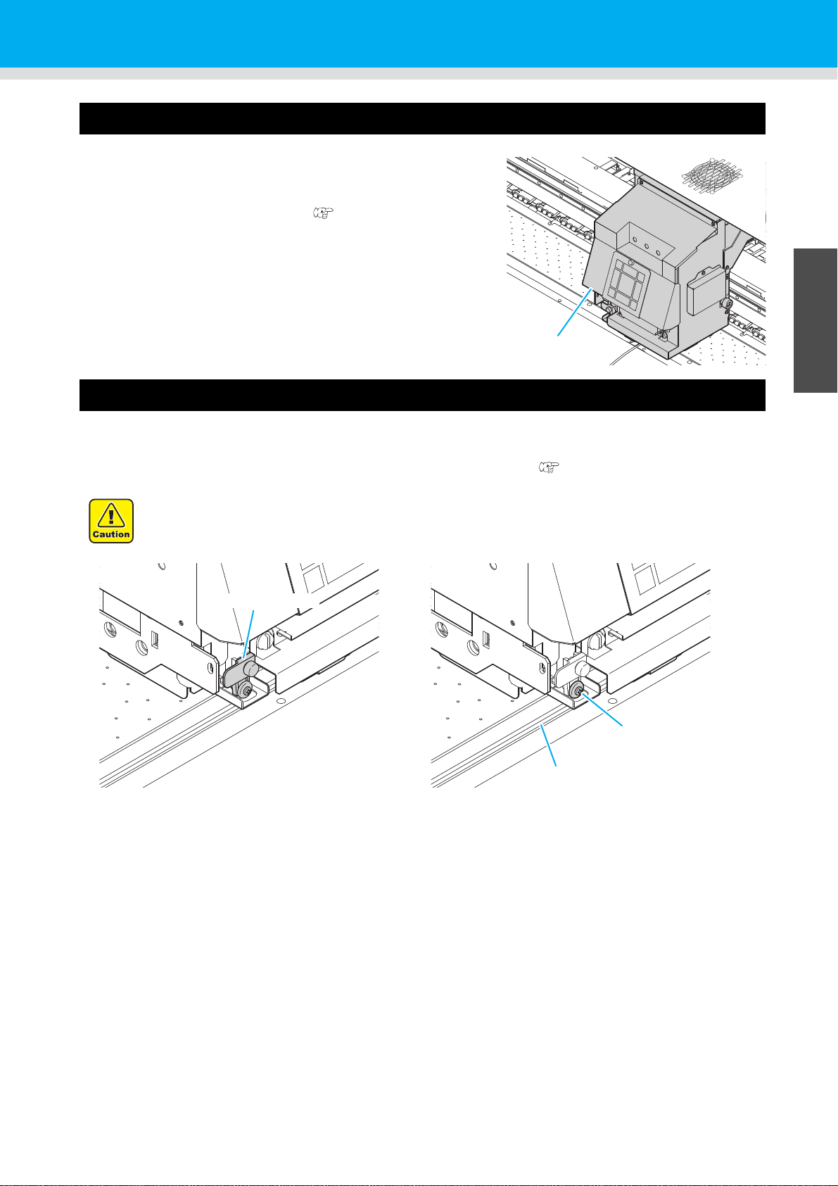
Adjusting the Head Height
Adjust the head height according to the thickness of the media you use.
• Turn OFF heater and perform this after temperature dropped.
• Adjust the head height prior to setting the media.If the head height is adjusted after the media is set,
this may cause a media jamming, deterioration of the print quality or head damage.
• The range of the initial head height is adjustable by 3 levels according to the purpose of use.
• The range of the printing height of Pro L4160/L4130 is from L (1.8 mm), M (2.3 mm), H range (2.8
mm). (Set to L range 1.5 mm at shipping)
1
2
3
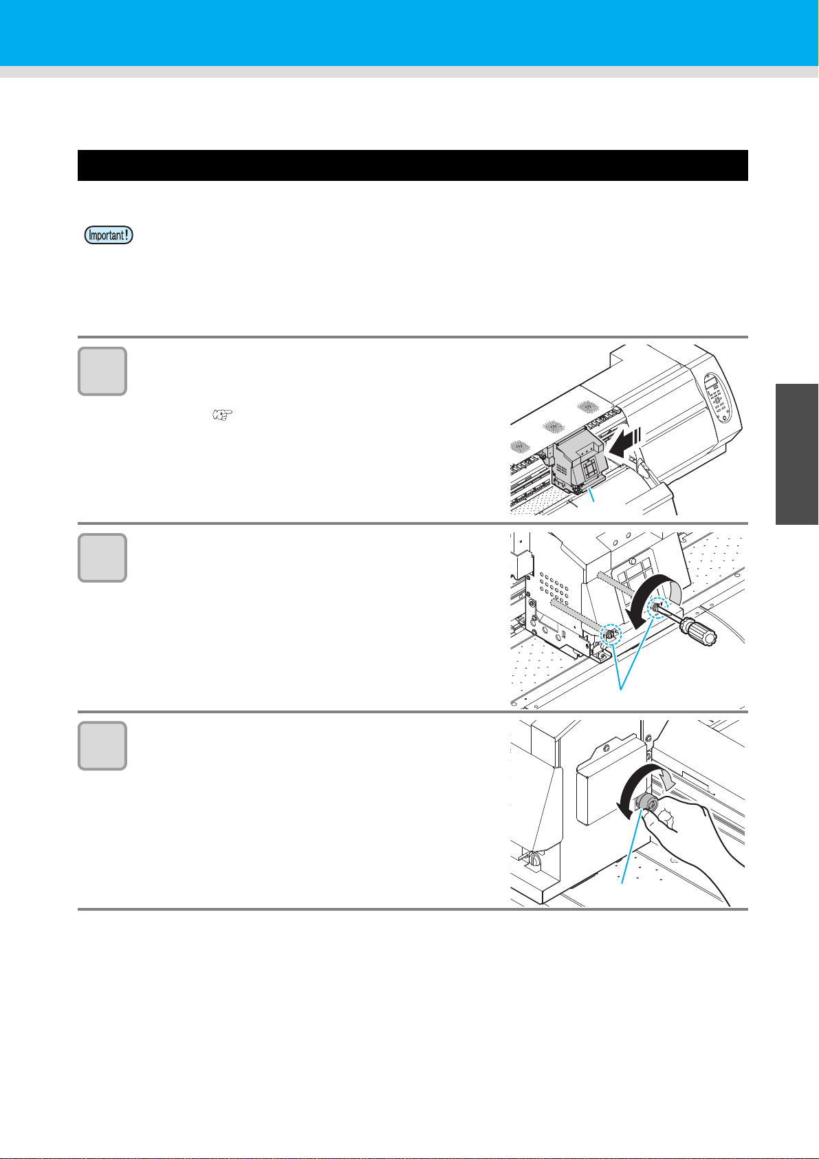
Move the carriage to the Media Transfer Surface.
• When the device is turned ON
:Execute [STATION - CARRIAGE OUT] of the Maintenance
functions.( P.4-5 Step1,2)
• When the device is turned off :
Open the front cover, then move the carriage by hand.
Loosen two screws located at the front.
• Loosen the screws, rotating each by one turn of a flat-blade
screwdriver.
Loosen two screws located at the front.
• The print head moves upward when you turn this lever to
the right (clockwise).
• The print head moves downward when you turn this lever to
the left (counter-clockwise).
1
2
Basic Operations
4
5
6
2-5
Page 44

4
Fix the carriage.
STAT I ON
COMPL E T ED [ EN T ]
5
Fix the carriage.
• Fastening the screw in front, you can fix the carriage.
• Fasten the screw securely.
Return the carriage to the station position.
• When the power supply is off, return the carriage to the
station manually.
• When the power supply is on, press the key if the
screen below is displayed.
6
Close the front cover.
2-6
Page 45

Note for media setting
OK
NoGood
Roll stopper arm
Roll
holder
Device
side
Roll stopper
Roll stopper arm
Roll stopper
Roll
holder
Device
side
When setting media, read the following notes carefully.
• Take care not to drop the media on a foot or so when the media is set. It may cause an
injury due to the media.
• There is a cutter inside the machine for cutting the print media. Do not touch any
parts other than the ones described in this manual when loading and replacing paper,
removing jammed paper, and cleaning the media transfer surface.
• Be careful not to get your fingers caught inside the machine and injured when replacing paper.
• Be careful not to get your fingers caught inside the machine when opening and closing the cover of the paper feed section.
• Hold the roll paper horizontally with both of your hands. When the roll paper is set in
the paper holder, the paper may fall off from the folder and cause injury if you hold
the holder vertically.
• The roll stopper arm works with the clamp lever. Do not push the clamp lever down
while roll stopper is caught between the roll stopper arm and this machine. The roll
stopper arm might be broken and roll stopper function
Setting a Media
*1
might be disabled.
1
*1. The function that once pulled out a certain amount of media, media pullout is temporarily locked.
2
Basic Operations
4
5
6
2-7
Page 46

Setting a roll media
Roll holder
fixing screw
Roll holder
Roll holder
Basis
Setting position
of 3inch tube
Setting position
of 2inch tube
Roll Holder Side
(The back of this machine)
Set the base position of roll holder
within this range.
• There are two types of the internal diameter
of the roll media paper tube: 2 inch and 3
inch.
• When using a media of greater width, set this so that the media width
can be more inside than .
• If a media is misaligned to the right/left more than fixed position, a
warning is displayed. Set the media again.
Do not set
outside this
mark.
Do not set
outside this
mark.
ERROR 516
MED I A S ET POS I T I ON R
ERROR 516
MED I A S ET POS I T I ON L
Move the roll holder located in the back of
1
the device to the direction of the middle of
the device.
• Loosen the roll holder fixing screw and then move it.
Check the clamp lever located in the back of the
2
device is lowered.
Move the roll holder to the roll setting position.
3
Roll Holder
Set Position
• Check the roll stopper is not caught between the roll stopper arm and this machine.
3 Inch Roll Media
2 Inch Roll Media
Roll Holder
Set Position
3 Inch Roll Media
2 Inch Roll Media
2-8
Page 47

4
Clamp lever
Pinch roller
5
6
7
Tighten the roll holder fixing screw.
• Check the Step 2 to 3 again.
Set the left end of the core of the roll media on the
left roll holder.
• Push the roll media onto the roll holder until the roll core is
all the way seated.
• Set the media so that the leading end of the media droops
down and toward the front.
Loosen the screw of the right side roll holder then
insert the holder into the core of the roll media.
• When the roll holder is not firmly pressed against the core
of the roll media, the feeding media may be loosened and
thereby the media reaches to the floor. ( P.5-10)
Tighten the screw of the roll holder
Setting a Media
1
8
9
Raise the clamp lever in the front of this machine.
Insert the roll media in this machine.
• The roll media can be smoothly inserted by slanting the media.
(1) Pull the media out of the roll to the head of the Media Transfer Surface.
(2) Insert the media between the Media Transfer Surface and the feed roller.
• Pull the media out of the roll so that the media can be grasped from the front of the machine.
(3) Push down the clamp lever from the back of this machine.
• The media is held.
2
Basic Operations
4
5
6
2-9
Page 48

10
Media press
Do not set outside
this mark.
Media
Media Press
ERROR 516
MED I A S E T POS I T I ON R
11
Pull out the roll media out.
(1) Open the front cover.
(2) Raise the clamp lever from the back of this machine.
(3) Pull out the roll media gently and then stop pulling when
locked lightly.
• When setting a medium, be sure to cover
the medium sensors located on the rear of
the Media Transfer Surface. The media
cannot be detected unless it is placed over
the sensor.
Make the roll media even then lower the clamp
lever.
• Pulling several positions of the media lightly, Lower the
clamp lever after confirming that the amount of the roll
media pulled out is almost even.
12
Hold the media with the media press gently.
• Set the media so that no media sticks out from the right end
pinch roller to the right side.
• When using a thick media, remove the media press from
the media before printing.
• In case that you use 240-mm wide or narrower media, media cannot be detected if
it is set in accordance with . Set media approximately 30mm inner than .
Do not set the media outside . As media may tilt and be lifted, it could break
•
the head.
2-10
• If a media is misaligned to the right more than fixed
position, a warning is displayed. Set the media
again.
Page 49
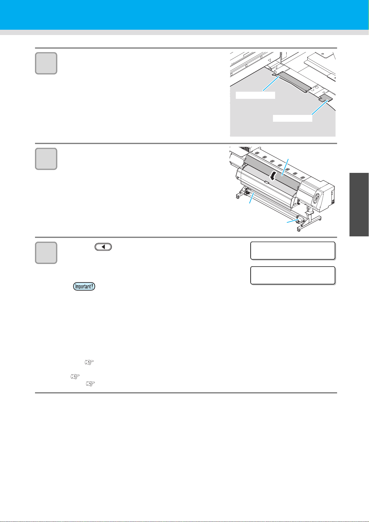
13
Media guide
Media press
Front cover
Paper core
Take-up
device
MED I A S E L ECT
ROLL < > L EAF
<Local >
Wi dth:1272mm
14
Hold the media with the media guide gently.
• If the printing result indicates that drying is not enough, use
the media guide to improve adhesion of the media to the
Media Transfer Surface.
• Use the media guide with it hit slightly against the sheet
holder.
• Make the media pass around the center of the claw of the
media guide.
Prepare for the take-up device.
(1) Set an empty core of the roll media on the take-up
device.
(2) Close the front cover.
Setting a Media
1
15
Press the key to select "ROLL" .
• Detects the media width.
• Width of the printable area that has been calculated from the detected
media width is displayed on the screen.
• Make sure that the width of the printable
area that has been detected is correct. The
printable width will be displayed shorter
than the actual media width by the left and
right margins (default: 30mm=left
15mm+right 15mm).
• Depending on the usage conditions and loaded media, the media width may not be detected correctly.
Perform the following if the media width cannot be detected correctly:
• Remove the media and then set it again.
• Make sure that the external lighting on the media surface does not interfere with the media sensor.
• Clean the media sensor by performing the procedure described in "Cleaning the Media Sensor"
( P.4-4), Cleaning.
• When [MEDIA REMAIN] of the machine setup is "ON"
( P.3-12), the screen for entering media remaining amount is displayed after detecting the media
width.( P.2-12)
2
Basic Operations
4
5
6
2-11
Page 50
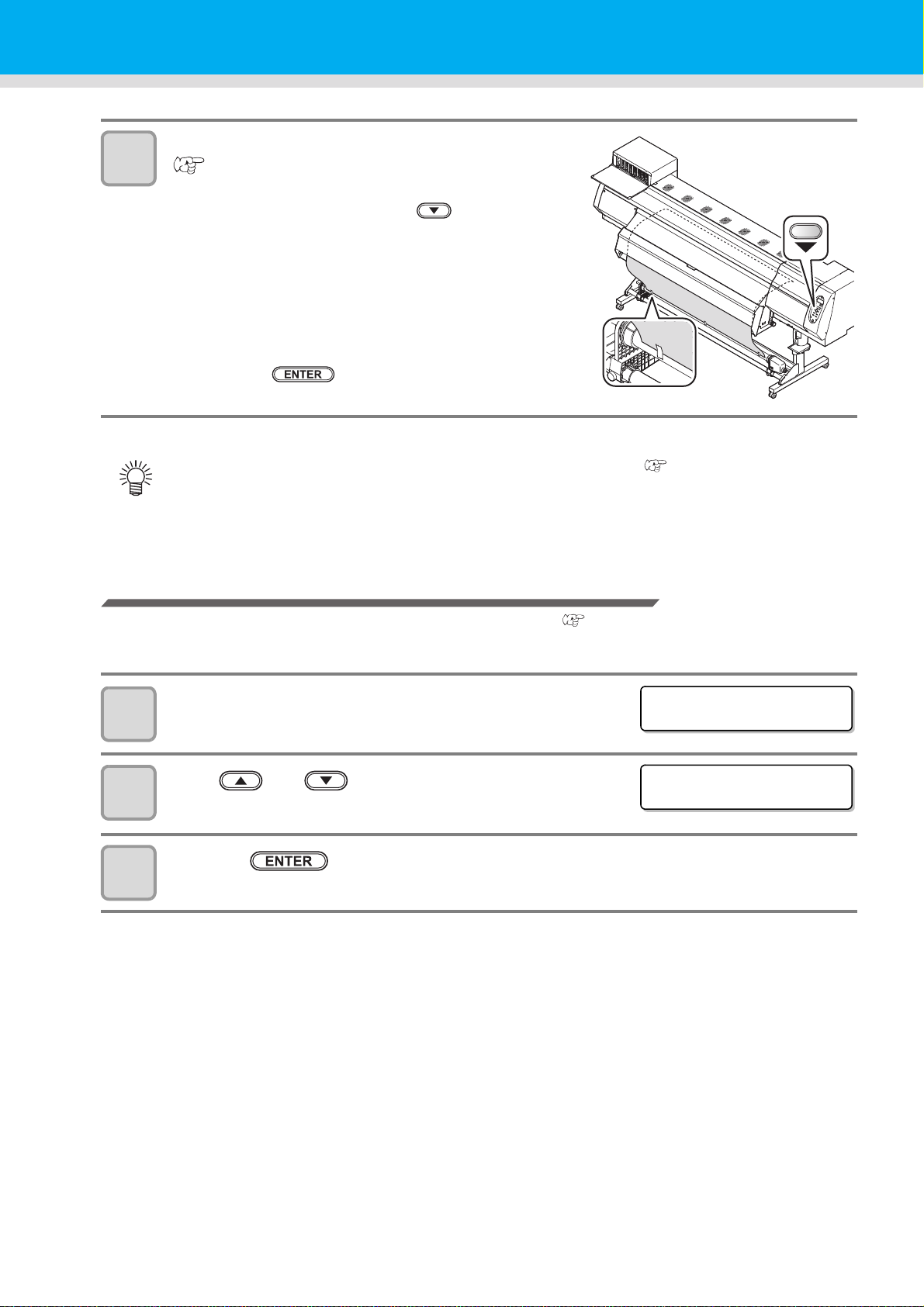
Fix the media on the take-up device.
INPUT MEDIA LENGTH
=50.0m
INPUT MEDIA LENGTH
=50.0m
16
( P.2-13)
(1) Feed the media up to the core of the roll media of the
take-up device by pressing the key.
• Check the media end is not caught into the slot on the
post-heater, and then feed the media.
(2) Fix the middle of the media with adhesive tape.
(3) In the same manner, fix the left side and right side of
the media.
• Make sure that the there is no slack or wrinkle on the
media in such condition that the roll media is pulled to
right and left evenly, and then stick the tape.
(4) Press the key.
• Depending on the media to use, attach/ remove the antistatic sheet. ( P.1-19)
• If media floats at the detecting position, it may not be detected correctly.
Entering the media remaining amount
When [MEDIA RESIDUAL] of the maintenance function is "ON" ( P.3-12), the screen for entering media
remaining amount is displayed after detecting the media width.
Display the screen for entering media remaining
1
2
amount.
Press and key to enter the media remaining
amount.
Press the key.
3
2-12
Page 51

Take-up device
50% of the maximum torque 100% of the maximum torque
Scale of the torque
Adjustment nut
With the switch of the take-up device, select the take-up direction of
the media or others.
Lever in top position (REVERSE) :
The take-up device winds the media with the printed side facing in.
Lever in middle position (OFF) :
The take-up device does not wind the media.
Lever in bottom position (FORWARD) :
The take-up device winds the media with the printed side facing
out.
Setting the torque limiter
Setting a Media
1
The take-up device is provided with a torque limiter.
The take-up torque can be adjusted with the torque limiter.
(The torque limiter is set at the maximum value when shipped from the factory.)
If the tension is too strong to use a thin or narrow sheet of media, lower the take-up torque with the torque
limiter.
• Clockwise turn :
Increases torque (a heavy and thicker media such as tarpaulin or the like)
• Counterclockwise turn :
Decreases torque (For thin or narrow media)
• When the torque limiter is adjusted too weak ;
The media can not be taken up firmly.
• When the torque limiter is adjusted too strong ;
The slack may occur depending on the media and cause influence on the image quality.
2
Basic Operations
4
5
6
2-13
Page 52

Setting leaf media
Pinch roller
Approximately
40mm
Media
Media press
Unlike roll media, leaf media does not need to be retained with the roll holders.
• After printing, in case that there is not a margin of more than 600mm from the edge, drying feed
cannot be fully performed. Therefore, please note that some places cannot pass the drying heater,
and drying unevenness and difference in printing quality occur.
• Depending on the condition of the media, a media jam may occur.
• Perform the following procedure if a media jam has occurred:
• Remove the media and then set it again.
• Set the leaf media in a way so that the leading edge of the media sticks out from the drying heater exit.
Open the front cover.
1
Raise the clamp lever.
2
Insert the leaf media between the Media Transfer
3
Surface and the pinch rollers.
• Set the media so that no media sticks out from the right end
pinch roller to the right side.
• Set the media so that the media end does not reach the slot
of the post-heater.
4
5
Push down the clamp lever.
• Align the leading edge of the media parallel
to the line on the heater. After lowering the
clamp lever, close the front cover and then
press .
Press to feed the media forward by
approximately 40mm.
Hold the media with the media press gently.
• Set the media so that no media sticks out from the right end
pinch roller to the right side.
• When using a thick media, remove the media press from
the media before printing.
2-14
Page 53

6
Media guide
MED I A S E L ECT
ROLL < > L EAF
** MEDIA DETECT **
Do not set outside
this mark.
Media
Media Press
ERROR 5 1 6
MED I A S E T PO S I T I ON R
7
8
Setting a Media
Hold the media with the media guide gently.
• If the printing result indicates that drying is not enough, use
the media guide to improve adhesion of the media to the
Media Transfer Surface.
• Use the media guide with it hit slightly against the sheet
holder.
• Make the media pass around the center of the claw of the
media guide.
Close the front cover.
1
Press the key.
Press the key to select "LEAF" .
9
The media detection is started.
10
Notes when using media press
(1) The media width is detected.
(2) The media is fed then the rear end of media is detected.
(3) It returns to the local mode when the detection is completed.
• In case that you use 240-mm wide or narrower media, media cannot be detected if it is set in
accordance with . Set media approximately 30mm inner than .
Do not set the media outside . As media may tilt and be lifted, it could break the head.
•
2
Basic Operations
4
• If a media is misaligned to the right more than fixed position, a
warning is displayed. Set the media again.
5
6
2-15
Page 54

Changing the printing origin
OR I G I N SE T UP
0.0 ----
OR I G I N SE T UP
0.0 0.0
Origin
(Length)
Origin
(Width)
OR I G I N SE T UP
** ORIGIN **
slot for cutting
approx. 75 mm
(X’)
25 mm
(Y’)
The position of the printing origin can be changed.
Moving the LED pointer to the changing position and deciding the position.
In Local, Press .
1
2
• It enters into the origin setting mode.
Set a light point of the LED pointer to the changing position by pressing
.
• Select the carriage and media, moving the point with
.
• When you press the key here, you can perform
media cutting.
• If the carriage is not covered by the ink cap for a long period
of time, the nozzle face of the head may get dry and
clogged, resulting in white lines being left in the printed
image.
• The buzzer sounds periodically while the carriage is out of
the capping station. The buzzer sounds at shorter interval
when the print heater temperature is high.
Setting a Media
After determining the origin, press the key.
3
• The printing origin is changed.
Typical setting position of printing origin
The printing origin in the depth direction (X') is positioned at about 75 mm rearward from the slot for cutting on
the Media Transfer Surface. The printing origin in the scanning direction (Y') is positioned at 15 mm from the
right end of the media. The value in the scanning direction (Y') can be changed using [MARGIN] in FUNCTION
mode.
( P.3-5) This can be changed by using the Jog key.
2-16
Page 55

Preparing for the Heaters
PRE PRT POST
23° C23° C23° C
Heater temperature
confirming display
OFF OFF OFF
(23° C23° C23° C)
The set temperature: 20 to 70°C
OFF OFF OFF
(23° C23° C23° C)
Current heater temperature
Changing the Temperature Settings for the Heaters
Set the heater temperature.
Depending on the media and the profile to use, set the heater temperature.
• It may take several minutes to tens of minutes for the set temperature to be reached, depending on the ambient
temperature.
• You can change the temperature set here also in [HEATER] of the [SETUP] menu. ( P.3-2)
Press the key.
1
Press the key.
2
1
3
4
Press to set the temperature of
each heater.
Heater selecting : Select with
Temperature setting : Set with
• The heater starts to get hot.(The [HEAT] lamp lights in orange.)
• When the heater temperature reaches the set temperature, the [HEAT] lamp goes off and the
[CONSTANT] lamp lights in green.
Press the key to end the setting.
• The screen moves to the temperature setting of FAN HEATER.
• The Heater temperature is controllable at the RIP side if the RIP in use has a function controllable.
(For the setting procedures, refer to the instruction manual of the RIP in use.)
• Depending on the power supply voltage, amount of heat generation differs. For the power supply
voltage of 100V to 120V, it may not reach 70 °C.
• If you set [VACUUM] of the [SETUP] menu more than needs, it may cause temperature decrease of
the print heater.
• Use this machine under 20 to 30°C. The temperature may not reach the set value due to the
environmental temperature condition.
• When you lower the heater temperature, ensure drying time with the procedures below:
• Set [SET UP] – [DRYING TIME].
• Increase the number of printing passes.
• Print unidirectionally.
2
Basic Operations
4
5
6
2-17
Page 56
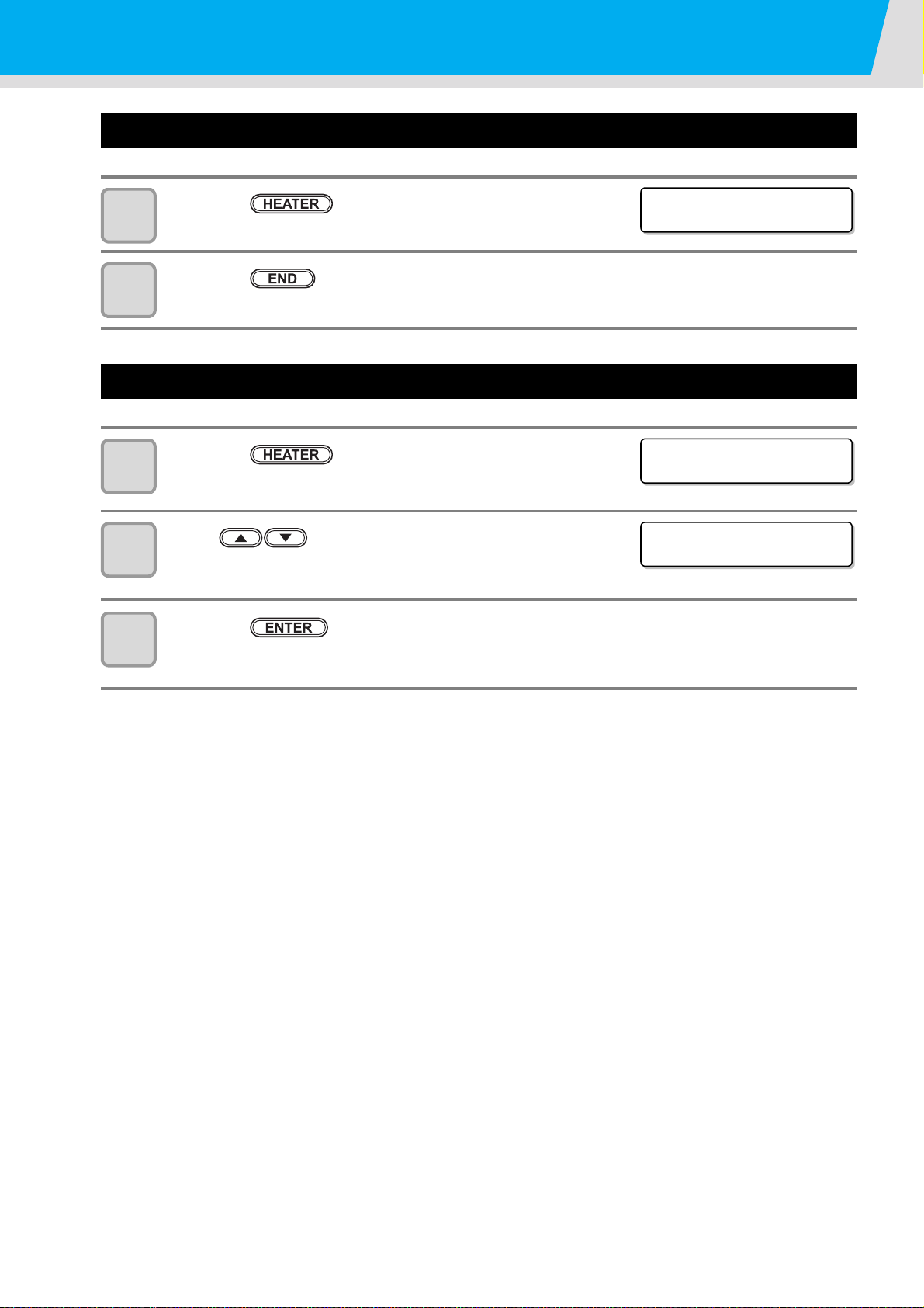
Preparing for the Heaters
PRE PRT POST
35° C40° C50° C
FAN HEATER
:READY( 10°C)
FAN HEATER
:READY( 20° C)
Checking the Heater Temperature
Press the key.
1
2
• The current heater temperature is displayed.
Press the key at the end of confirmation.
• The screen returns to LOCAL.
Changing the Temperature Settings for the Drying Heater
Press the key three times.
1
to
2
3
Press to select a set value.
• Set value : OFF / POST setting value+1 to 20°C
Press the key to end the setting.
• The screen returns to LOCAL.
2-18
Page 57

Test Feeding
TEST FEED
[ENT]
BACKWARD FEED
:ON
BACKWARD FEED
:ON
TEST FEED
START [ ENT ]
** TEST FEED **
PLEASE : WA I T
Since heater is used at high temperature, cockles may occur in some of your media. (P.5-10)
Perform this function before printing, and check whether the media can be fed normally.
Press the key in LOCAL three
1
times.
Press the key.
2
Press to select ON/OFF.
3
• When setting "ON", rewind the roll media
to take up the slack before printing.
Press the key.
4
1
5
6
Press the key.
• Start test feeding.
Press the key.
• The feeding operation is continued until you press the key.
• Feed it to some extent and check the feeding status, and then press the key to terminate.
2
Basic Operations
4
5
6
2-19
Page 58
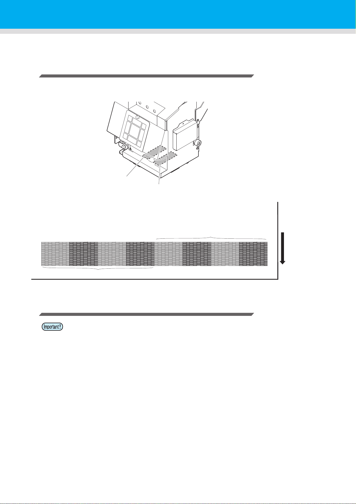
Test Printing
Pattern of head 1
Pattern of head 2
Head 1
Head 2
Media advance
direction
Print a test pattern to check that there are no discharging defects such as nozzle clogging (slight touching of ink
or nozzle missing).
Relationship between head row and test pattern
The relations between head row and test pattern print position are as follow.
Note on test printing
• When using a roll medium, rewind the medium by hand before printing so that it is not loose.
When the roll medium has not been rewound tightly, it may cause image quality to
deteriorate.
2-20
Page 59

Test Printing
Media-feeding direction
: When the set value is "FEED DIR."
: When the set value is "SCAN DIR."
TEST PR I NT
(SCAN DIR. ) [ENT ]
** PRINTING **
PLEASE WA I T
TEST PR I NT
(SCAN DIR. ) [ENT ]
Abnormal pattern
Nozzles are clogged
Normal pattern
Nozzles are dirty
Test Printing
Print a test pattern to check that there are no discharging defects such as nozzle clogging (slight touching of ink
or nozzle missing).
In addition, you can select the orientation of the test pattern to print from two types in order to perform test
printing repeatedly. Select one depending on your use.
1
Check before test
printing.
Press the key in LOCAL.
1
2
3
• Press to change the test pattern orientation.
Press the key.
• Test printing starts.
• When the printing has been completed, the screen returns to step1.
Check the printed test pattern.
• When the result is normal, end the operation.
• When the result is abnormal, perform head cleaning.( P.2-22)
• If a media has been set P.2-5 • If the origin position has been set
• If the head height has been adjusted P.2-5
2
Basic Operations
4
5
6
2-21
Page 60

Head Cleaning
CLEANI NG
SOFT [ ENT ]
CLEANI NG
HARD [ ENT ]
SELECT HEAD
:12
SELECT HEAD
:1_
12 1_ _2
** CLEANING **
PLEASE : WA I T
About head cleaning
Check the printed test pattern result and perform cleaning depending on the status.
Select one from the three types below:
SOFT : When lines are bent, when any line is missing
NORMAL : When any line is missing, when colors are mixed
HARD : When poor image quality cannot be improved even by NORMAL or SOFT cleaning
Perform head cleaning depending on the test printing result
There are three types of head cleaning. Use one by checking the test pattern.
In Local, Press the key two times.
1
2
3
4
5
6
Press to select the cleaning type.
SOFT : When lines are bent, when any line is missing
NORMAL : When any line is missing, when colors are mixed
HARD : When poor image quality cannot be improved even by NORMAL or SOFT cleaning
Press the key.
Press to select a head to
cleaning.
• Set Value : 12 (Cleaning both heads.)
1_ (Cleaning Head 1 only.)
_2 (Cleaning Head 2 only.)
Press the key.
• On completion of cleaning, the screen returns to step1.
Perform test printing again, and check the result.
• Repeat the cleaning and the test printing until the drawing result becomes in normal.
When the image quality is not improved after the head cleaning.
• Clean the wiper and ink cap. ( P.4-5)
• Wash the head nozzle. ( P.4-17)
• Solve the failure of the image quality, referring to When Nozzle Clogging Cannot Be Solved.
2-22
(P.4-22)
Page 61

Set the media feeding
Second band
First band
Media advance direction
FEED COMP .
<ENT>
FEED COMP .
PR I NT [ ENT ]
** PRINTING **
PLEASE WA I T
FEED COMP .
=0
When entering the value in “+”
0
When entering the value in “-”
In case that patterns overlapsInput example: In case that patterns are separate
Correct the feeding rate of media.
If the correction value is not appropriate, stripes may appear on the printed image, thus resulting in a poor
printing.
• When you have changed the media type, check the pattern and perform adjustment depending on the
status.
• When you have changed the temperature of the heaters, make sure that the [CONSTANT] lamp lights
up and that the preset temperature is reached, and then start the correction.
• When using a roll medium, rewind the medium by hand before printing so that it is not loose. When
the roll medium has not been rewound tightly, it may cause image quality to deteriorate.
• When printing with a take-up device, set the media first and then perform media correction.
Setting Feed Correction
A pattern for media correction is printed and a media-feeding rate is corrected.
• Two bands are printed in the correction pattern.
• Make adjustment so that an even color density is obtained in the boundary between the two bands.
• If the correction pattern that has been printed on a media such as transparent film is difficult to
discern, feed the media forward so that the printed area is out of the drying heater, place a sheet of
paper on the back of the media, and then rewind the media.
• When making adjustment to the media-feeding rate, use of a magnifying glass is recommended.
1
1
2
3
4
2
Basic Operations
Set a media. ( P.2-5)
Press the key in LOCAL.
Press the key.
4
Press the key to print a correction pattern.
Check the correction pattern and enter a correction
5
value.
Enter a correction value in "+": The boundary between the two bands is widened.
Enter a correction value in "-": The boundary between the two bands is narrowed.
5
6
2-23
Page 62

Set the media feeding
FEED COMP .
PR I NT [ ENT ]
*REMOTE*
**. **mm
FEED COMP .
0
X
0
Current [FEED COMP.] value
*REMOTE*
**. **mm
Press the key.
6
• Print a correction pattern again and check it.
• When media correction is needed, perform the operation in Step 5
to make correction.
Press the key several times to end the setting.
7
Performing the station maintenance without key
You can select “FEED COMP.” by using the key in the Local without pressing the key.
Press the
key in Local.
Press to
select [SETUP].
Press the key twice.
• It becomes the same condition as the
key is pressed from Local.
Correcting Media-feeding during Printing
A media-feeding rate can be corrected even in the remote mode or when image data is printed.
Press the key in the Remote.
1
Press to enter a corrected feeding rate.
2
• Corrected feeding rate: -255 to 255
• The value entered here is reflected in the corrected feeding rate soon.
Press the key.
3
2-24
• The changed value is registered.
• When you press the key instead of the key, the
value entered here will be invalid.
Page 63

Correct the ink drop position for bidirectional printing
The dots at the fourth position counted from the zero
position in the positive direction form a straight line.
In this case, the dot position correction value is 4.0.
Output
direction
DROP . POS c o r r e c t
[ENT]
DROP . POS c o r r e c t
:Y600dp i
DROP . POS c o r r e c t
:Y600dp i
DROP . POS c o r r e c t
PR I NT [ ENT ]
** PRINTING **
PLEASE WA I T
PATTERN1
=0.0
When the condition for printing (media thickness/head height/etc.) has been changed, perform the following
operation to correct the ink drop position for bidirectional (Bi) printing and obtain the proper printing result.
Example of a Drop Position correct Printed Pattern
• The correction pattern for aligning the ink drop position cannot be printed on a media whose width is
less than 450 mm. Print quality cannot be guaranteed in such a case. Use unidirectional printing.
1
1
2
3
4
5
6
Set a media on the machine and set a printing origin. ( P.2-5)
Press the key twice in LOCAL.
Press the key.
Press to select the resolution.
• Setting value: Y600dpi / Y900dpi / Y1200dpi
• Perform correction for all resolutions.
Press the key.
Press the key to start pattern printing.
• Test pattern is printed. (The printed patterns are called Pattern 1,
Pattern 2, Pattern 3... in the order of printing.)
2
Basic Operations
4
Press to correct the dot position of Pattern
7
1~.
• Corrected feeding rate: -40.0 to 40.0
• Open the front cover and check the test patterns. The position where an outward feeding line and a
return feeding line become one straight line is the correction value.
• When the correction value in not between -40.0 and 40.0, adjust the height of the printing heads and
then perform the operations in Step 2 and later.
5
6
2-25
Page 64

Correct the ink drop position for bidirectional printing
Press the key.
8
• Next test pattern is printed.
• Repeat step6 and step7.
Press the key several times to end the setting.
9
Performing to correct the dot position without key
You can select “DROP.POScorrect” by using the key in the Local without pressing the
key.
Press the
key in Local.
Press to
select [SETUP], and
press the key.
Press to select [DROP.POScorrect],
and press the key twice.
• It becomes the same condition as the
key is pressed from Local.
2-26
Page 65

Printing Data
Checking the Status of Ink Cartridges
Check the status of the ink cartridges before you start printing. If the amount of the remaining ink is low, or the
[NEAR END] or [INK END] message is displayed, replace the ink cartridge.
• Checking the Ink Cartridges
→ Displaying the Information of this machine ( P.3-21)
• When the ink cartridge is nearly empty
• When [NEAR END] warning is displayed
• When [INK END] warning is displayed
→ Changing an ink cartridge ( P.1-16)
• While [NEAR END] warning is displayed, the current mode returns to LOCAL after each printing has
been completed. You cannot make multiple prints consecutively.
• When [INK END] error occurs while making a print, printing stops and the current mode returns to
LOCAL.
• Printing cannot be started while [INK END] warning is being displayed.
Checking the Status of Waste Ink Bottle
1
Check the condition of the waste ink bottle before you start printing. If the bottle is nearly full, or a waste ink
bottle confirmation message is displayed, replace the bottle.
• Checking the Waste Ink Bottle
→ Confirming Machine Information ( P.3-19)
• The waste ink bottle is nearly full
• A waste ink bottle confirmation message is displayed
→ Replace the waste ink bottle with another ( P.4-30)
• When a waste ink bottle confirmation message appears while making a print, printing stops and the
current mode returns to LOCAL.
• Printing cannot be started while a waste ink bottle confirmation message is being displayed.
2
Basic Operations
4
2-27
5
6
Page 66

Starting a Printing Operation
TEMPERATURE CONTROL !
PLEASE WA I T
*REMOTE* 1200x1200 R
16 .Bd .VD. x2 xx . xxm
Resolution
Number of passes
The length of
media drawn
Scan direction
Ud : Unidirectional
Bd : Bidirectional
Data type
VD : Variable data
ND : Normal data
Scanning speed
x1 : Standard
speed
x2 : Double
speed
With/ without nozzle
recovery setting
• When using a roll media, rewind the media by hand before printing so that it is not loose.When the roll
media has not been rewound tightly, it may cause the image quality to deteriorate.
• When making a test print, printing the actual image data is recommended. Depending on the image
data, you may not be able to achieve the desired image quality.
Setting a Media ( P.2-5)
1
Checking the Heater Temperature
2
• Check the CONSTANT lamp lights in [PRE], [PRINT], and
[POST] below the display.
Press the key in LOCAL.
3
4
• If the heater temperature has not reached the setting value, the
right screen is displayed.
Even if it has not reached, you can move to REMOTE when
pressing the key.
• The screen changes to REMOTE, and data can be received from
the PC.
Transmit data to be printed from the PC.
• The ACTIVE lamp blinks and the printing conditions are
displayed.
• For the method of data transmission, see the instruction
manual for the output software.
Start printing.
5
2-28
Page 67
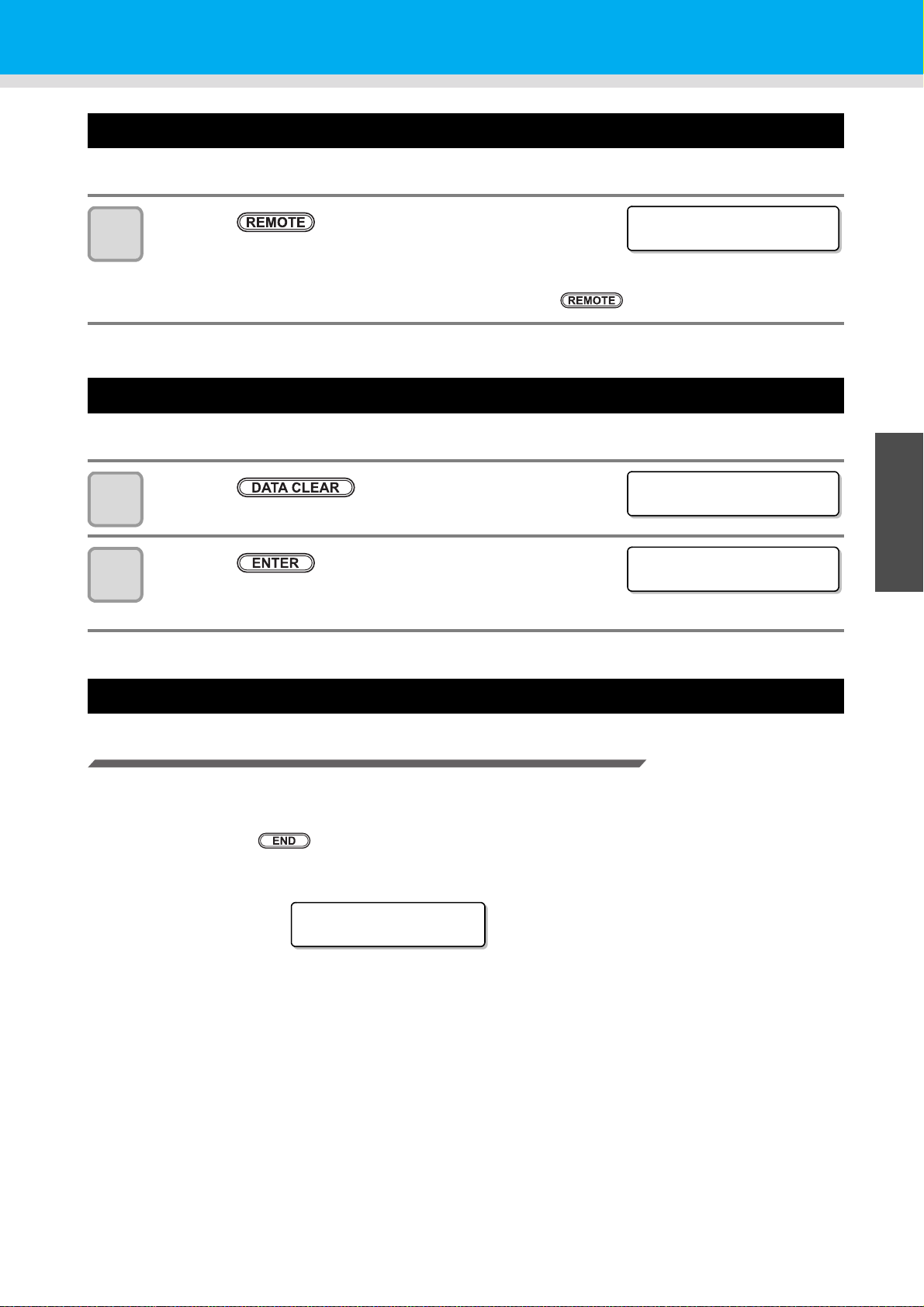
Stopping a printing operation halfway
<LOCAL>
width : 1272mm
DATA CL EAR
[ENT]
** DATA CLEAR **
Dr y i ng
∗∗: ∗∗ : ∗∗
Perform the following operation when stopping a printing operation halfway.
Press the key during printing.
1
• The printing operation stops.
• Interrupt data sending at the PC side during the data is sent from the
PC.
• Printing restarts from the interrupted data by repressing the key.
Printing Data
Deleting Received Data (Data Clear)
When you want to stop printing, delete the already received data.
Press the key in LOCAL.
1
Press the key.
2
Behavior after printing has been completed
Drying Feed
When printing has been completed, the feeding operation is performed to dry the printed surface with the
drying heater.
• Perform the feeding operation until the back edge of printing passes the drying heater.
• When you press the key, the operation is terminated.
• When the machine has been received next data continuously, it will operate after the last data is received.
• The ACTIVE lamp goes out.
• The received data is erased then it returns to the local mode.
1
2
Basic Operations
Screen display during drying feeding
4
5
6
2-29
Page 68
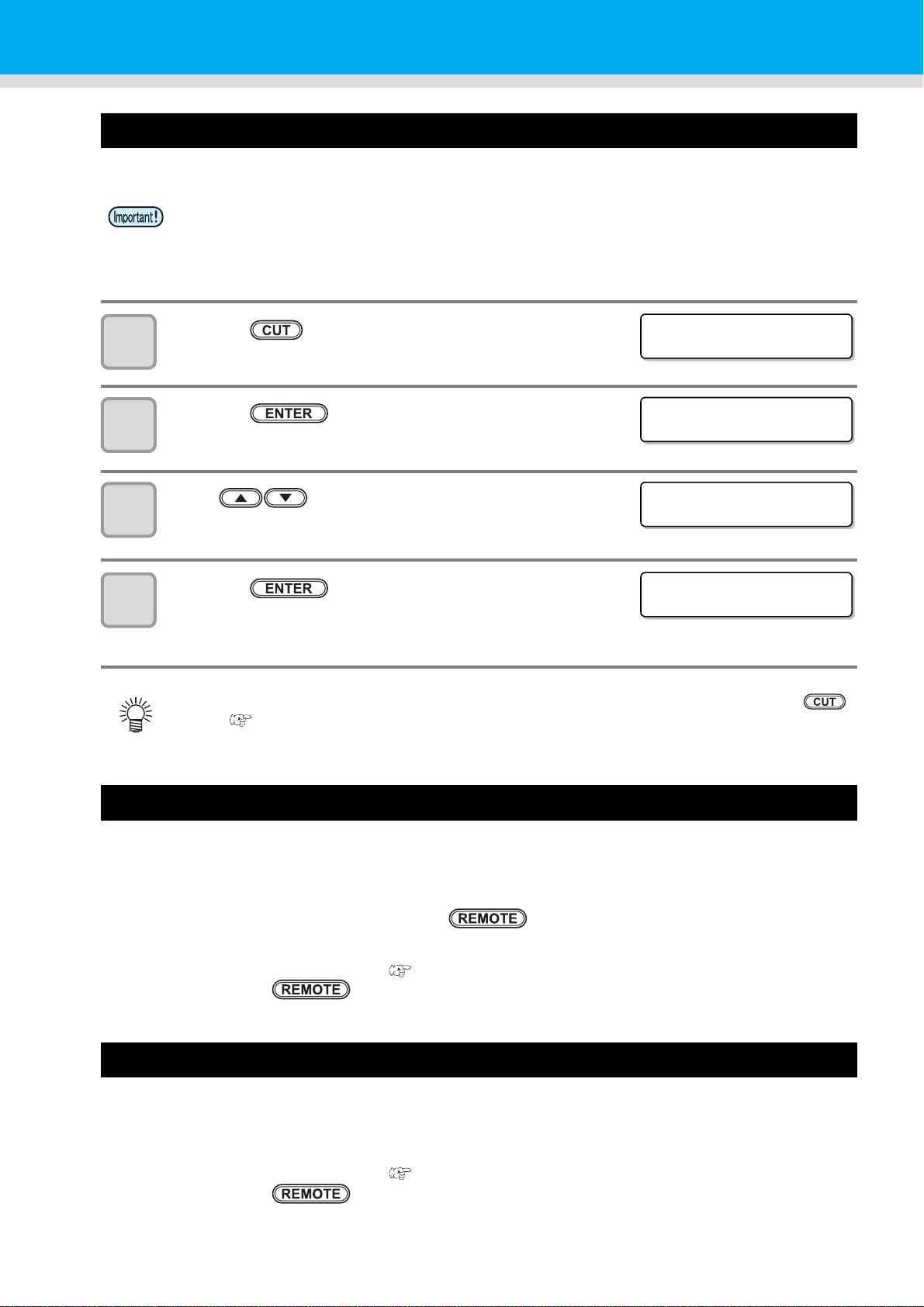
Cutting a media
MED I A C UT
[ENT]
MED I A C UT
CUT POS I T I ON [ ]
CUT POS I T I ON
0.0 ----
** CUTTING **
PLEASE WA I T
For a roll media, two ways are available to cut the media after printing is completed, as follows.
• When a media is cut, be careful that the printed side does not touch the floor or the printed side of
other already cut media.
• When using the take-up device, take up a cut medium using the switch of the take-up device.
Press the key.
1
Press the key.
2
Press to specify the cutting position.
3
Press the key.
4
• The media is cut.
• When the cutting has been completed, the current mode returns to LOCAL.
• During the origin setting with the jog keys, you can also perform media cutting by pressing the
key. ( P.2-16)
When [NEAR END] error occurs while printing
The following occurs when [NEAR END] error occurs while printing:
• When each printing has been completed, the current mode returns to LOCAL.
• When each printing has been completed, the current mode returns to LOCAL even if you are making multiple
prints consecutively (cannot perform continuous printing).
• Subsequent printing starts when you press the key, but the current mode returns to LOCAL after
each printing has been completed.
• In order to resume continuous printing, clear [NEAR END] message by performing the following procedure:
(1) Changing an ink cartridge ( P.1-16)
(2) Press the key.
When [INK END] error occurs while printing
• Printing is canceled, and the current mode returns to LOCAL.
• Printing cannot be started while [INK END] warning is being displayed.
• In order to resume printing from where it has been paused, clear [NEAR END] message by performing the
following procedure:
(1) Changing an ink cartridge ( P.1-16)
(2) Press the key.
2-30
Page 69

Printing Data
When a waste ink bottle confirmation message appears while printing
• Printing is canceled, and the current mode returns to LOCAL.
• Printing cannot be started while a waste ink bottle confirmation message is being displayed.
• In order to resume printing from where it has been paused, clear the waste ink bottle confirmation message.
(1) Replace the waste ink bottle with another. ( P.4-30)
(2) Press the key.
1
2
Basic Operations
4
2-31
5
6
Page 70

2-32
Page 71

Chapter 3
Extended Functions
This chapter
describes the operation procedures for using the machine more conveniently and each
setting procedure.
List of Functions ............................................3-2
Setting Logical Seek ..................................... 3-3
Setting Drying Time ......................................3-4
Setting Margins .............................................3-5
Perform setting to reduce stripes between
passes ...........................................................3-6
Setting Auto Cleaning ................................... 3-7
Setting nozzle face cleaning time .................3-8
Other Settings ...............................................3-9
Machine Settings ........................................3-10
Setting a AUTO Power-off.......................... 3-11
Setting the Display of Media Residual ....... 3-12
Setting Time ............................................... 3-14
Setting Units............................................... 3-15
Setting a KEY BUZZER ............................. 3-16
Setting a LANGUAGE.................................3-17
Initializing the Settings ................................3-18
Confirming Machine Information .................3-19
Displaying the Information ..........................3-19
Check such as the machine version
information..................................................3-21
Displaying the Information of
this machine................................................3-21
Page 72

List of Functions
This section describes the overview of each function to be set and set values that can be registered in user
types.
• About default “HOST” function
You can operate this by the setting value specified in RIP software.
When you set to other than “HOST”, it operates by that setting value, not by the instruction from RIP
software.
Depending on RIP software, there are some functions that cannot be instructed by software. In such a
case, it operates by the setting value of “When no instruction from RIP exists”.
• For the specifying method with the RIP software, refer to the operation manual of the RIP software.
Function name Set value Default
FEED COMP. ( P.2-23) -9999 ~ 0 ~ 9999 0
DROP. POS CORRECT -40.0 ~ 0 ~ 40.0 0
Pre-Heater
HEATER
( P.2-17)
LOGICAL SEEK
INK LAYERS ( P.3-9) HOST /1 ~ 9 HOST
DRYING
TIME
(P.3-4)
MARGIN
(P.3-5)
VACUUM ( P.3-9)
FEED SPEED ( P.3-9) HOST / 10 ~ 200% HOST
MAPS
(P.3-6)
AUTO
CLEANING
(P.3-7)
INTERVAL
WIPING
(P.3-8)
*1. This is the setting value to be used for printing when setting value is not specified at the RIP software (host) side, or, you give priority
*2. The setting value range shall be within the POST heater setting value +20 ℃ .
*3. When you set this to “100%” or more, required time for completion of printing will be shortened. However, enough drying time cannot
Post Heater
FAN HEATER
18)
(P.3-3)
SCAN HOST /0.0 ~ 9.9 sec HOST
LEFT
RIGHT
OFF / ON OFF
(P.2-
PRINT SPEED
ADJUST
INTERVAL
TYPE
TYPE1
TYPE2
to the setting value at the machine side, even if you set “Host” to the type registration of this machine.
be ensured and it may affect the image quality.
OFF/ 20 ~ 70°C
(OFF/ 68 ~ 122°F)
OFF/ 20 ~ 70°C
(OFF/ 68 ~ 122°F)
OFF/ 20 ~ 70°C
(OFF/ 68 ~ 122°F)
OFF/
POST+0 ~ 20°C
HOST / ON / OFF HOST
HOST / -10 ~ 85mm
(1mm unit)
HOST / -10 ~ 85mm
(1mm unit)
HOST / STANDARD /
STRONG
-50 ~ +50% 0%
OFF / 1 ~ 1000 page OFF
SOFT / NORMAL /
HARD
Lv1 ~ Lv6,
MANUAL(90~600sec)
Lv1 ~ Lv6,
MANUAL(10~90min)
*2
OFF
OFF
OFF
OFF
HOST
HOST
HOST
SOFT
Lv4
Lv4
When no instruction
from RIP exists
*1
OFF
1
0.0 sec
0 mm
0 mm
STANDARD
100%
Outline
Used to print a pattern for
correcting a media-feeding rate
and correct it.
Used to adjust the dot position in
go and return printing.
Sets heater conditions.Print Heater
Sets drying heater conditions.
Sets the scan movable area
during printing.
Sets the number of layers in
which ink is to be applied.
Sets the time to wait for ink
drying.
Sets a non-printing area along
the right and left edges of the
media.
Sets the absorbability of the
media.
Changes the media feeding
speed in printing.
Perform setting to reduce stripes
between passes.
Sets the automatic cleaning
operation of the head at the start
of printing.
Set wiping interval performed
during printing.
*3
3-2
Page 73

Setting Logical Seek
UNI-DIRECTIONAL BI-DIRECTIONAL
Movement of heads when
LOGICAL seek is OFF
Movement of heads when
LOGICAL seek is ON
UNI-DIRECTIONAL BI-DIRECTIONAL
MACHINE LENGTH MEDIA
FUNCT I ON
SETUP [ ENT [
SETUP
FEED COMP . [ ENT ]
SETUP
LOGICAL SEEK [ ENT ]
LOGICAL SEEK
:HOST
LOGICAL SEEK
:OFF
SETUP
LOGICAL SEEK [ ENT ]
The motion of Head varies depending on the set of Logical-seek.
• You cannot specify the logical seek at the RICOH Software RIP side. When you set this machine to
“Host”, printing will be performed in “LOGICAL SEEK=OFF” status.
• When you set this to “ON” or “HOST”
Required time for completion of printing will be shortened. However, enough drying time cannot be
ensured and it may affect the image quality.
1
Press the key in LOCAL.
1
Press the key.
2
Press to select [LOGICAL SEEK].
3
Press the key.
4
Press to select a set value.
5
6
• Set value : HOST / ON / MEDIA LENGTH / MACHINE LENGTH
Press the key.
1
3
Convenient use
5
Press the key several times to end the setting.
7
6
3-3
Page 74

Setting Drying Time
FUNCT I ON
SETUP [ ENT ]
SETUP
FEED COMP . [ ENT ]
SETUP
DRY I NG T I ME [ ENT ]
SCAN
=HOST
SCAN
=HOST
SETUP
DRY I NG T I ME [ ENT ]
In the drying time setting, the following items for ink drying time are set.
• SCAN : Ink drying time for each scanning is set. (During bidirectional printing, the machine stops for a
certain period of time specified for each of the outward and return scanning.)
• When you give priority to the setting at the RICOH Software RIP side, make the setting value “Host”.
• “SCAN” set in this machine is displayed as “Pause Time per Scan” in the RICOH Software RIP.
Press the key in LOCAL.
1
Press the key.
2
Press to select [DRYING TIME].
3
4
5
6
7
Press the key.
Press to set drying time for scanning.
• To enable the drying time specified in your RIP, select “Host”.
• Scanning setting value : Host or 0.0 sec. to 9.9 sec.
Press the key.
Press the key several times to end the setting.
3-4
Page 75

Setting Margins
FUNCT I ON
SETUP [ ENT ]
SETUP
FEED COMP . [ ENT ]
SETUP
MARG I N [ E NT ]
LEFT
=HOST
LEFT
=0mm
RIGHT
=HOST
RIGHT
=0mm
SETUP
MARG I N [ E NT ]
Set a non-printing area along the right and left edges of the media.
The offset value against the standard margin 15mm is set hereupon.
• When you give priority to the setting at the RIP software side, make the setting value “Host”.
• You cannot specify the margins at the attached RIP software (RICOH Software RIP). When you use
the RICOH Software RIP, if you set this machine to “Host”, printing will be performed in “Margins for
right and left off set value= 0 mm” status.
Press the key in LOCAL.
1
Press the key.
2
Press to select [MARGIN].
3
1
4
5
6
7
8
9
Press the key.
Press to set the left margins.
Set Value :HOST or -10 to 85mm (in 1mm increment)
Press the key.
Press to set the right margins.
Set Value :HOST or -10 to 85mm (in 1mm increment)
Press the key.
Press the key several times to end the setting.
1
3
Convenient use
• Pay attention to that printing may start on the media press if a right and left margin is set to 5
mm or less when the media press is used in printing.
5
6
3-5
Page 76

Perform setting to reduce stripes between passes
FUNCT I ON
SETUP [ ENT ]
SETUP
FEED COMP . [ ENT ]
SETUP
MAPS [ EN T ]
MAPS
:OFF
MAPS
:ON
PR I NT SPEED ADJUST
=0%
PR I NT SPEED ADJUST
=10%
SETUP
MAPS [ EN T ]
In case that feeding stripes cannot be resolved even though media correction (P.2-23) is performed, make
MAPS(Media Advance PassSystem) valid. Feeding stripes become less visible by distributing the pass
boundary.
• Depending on the printing condition, the effect cannot be recognized.
Press the key in LOCAL.
1
Press the key.
2
Press to select [MAPS].
3
4
5
6
7
8
Press the key.
Press to set ON/OFF.
• Set Value : OFF, ON
Press the key.
• When you select OFF, proceed to the Step 9.
Press to change print speed.
• Set Value : -50 ~ +50%
• When you speed up, nozzle recovery effect cannot work in some cases. Use it after
checking.
Press the key.
Press the key several times to end the setting.
9
3-6
Page 77
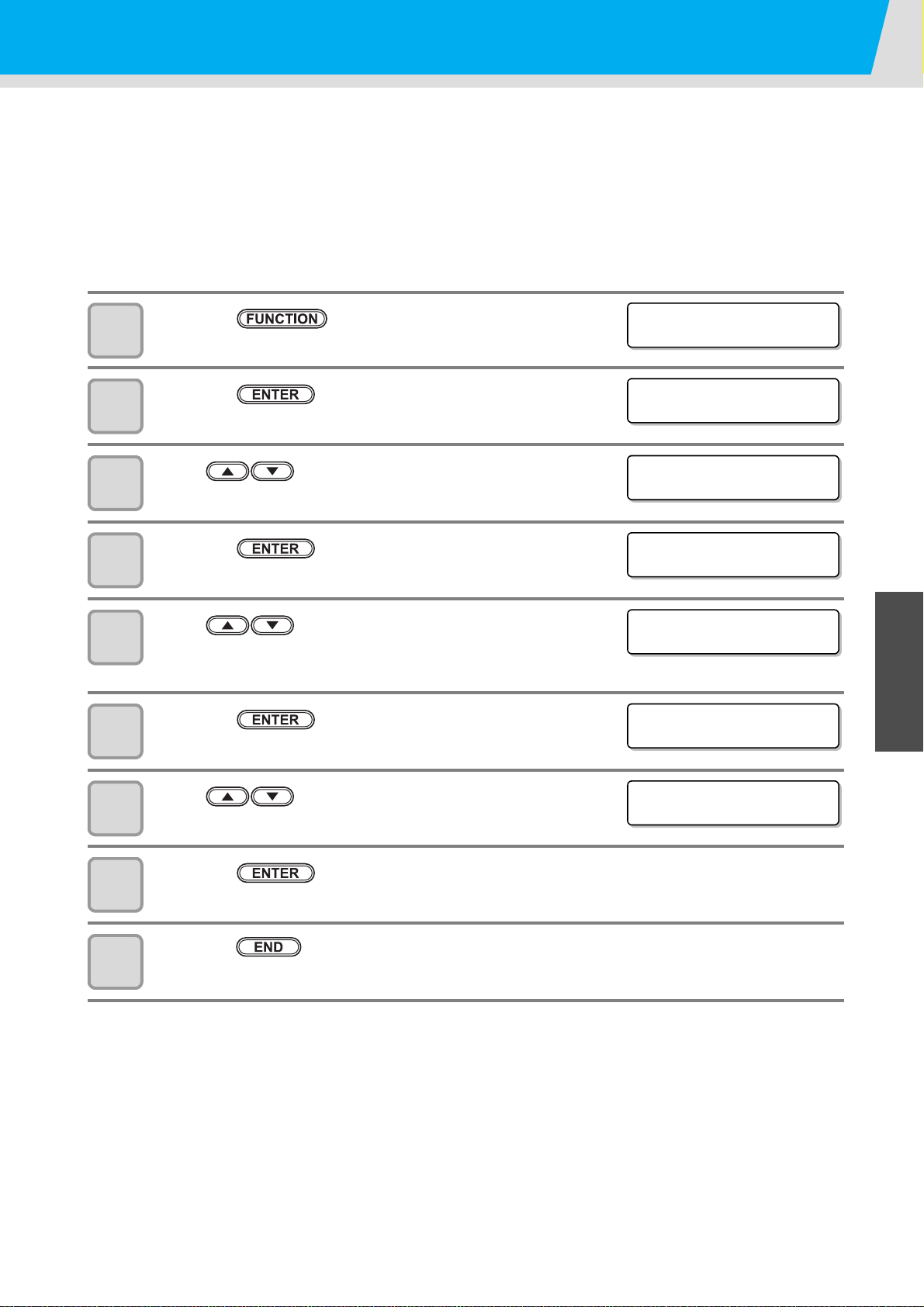
Setting Auto Cleaning
FUNCT I ON
SETUP [ ENT ]
SETUP
FEED COMP . [ ENT ]
SETUP
AUTO CLEAN I NG [ ENT ]
INTERVAL
=OFF
INTERVAL
= 1page
TYPE
:SOFT
TYPE
:NORMAL
You can set items so that the head cleaning is automatically performed when printing has been completed for
the set interval.
When printing has been completed, the machine count the print count printed after the previous head cleaning
and performs the cleaning automatically if necessary.
The machine can perform a stable printing operation with its heads always kept clean.
The first cleaning is performed immediately before the first printing after the machine is started. Then
subsequent cleaning is performed every printing on the specified count of print.
Press the key in LOCAL.
1
Press the key.
2
Press to select [AUTO CLEANING].
3
1
4
5
6
7
8
9
Press the key.
Press to set a cleaning interval.
• Set value : OFF / 1 to 1000page
• When selecting OFF, proceed to Step 8.
Press the key.
Press to set a cleaning type.
• Set value : NORMAL / SOFT / HARD
Press the key.
Press the key several times to end the setting.
1
3
Convenient use
5
6
3-7
Page 78

Setting nozzle face cleaning time
FUNCT I ON
SETUP [ ENT ]
SETUP
FEED COMP . [ ENT ]
SETUP
INTERVAL WIPING[ENT ]
INTERVAL WIPING
:TYPE1
INTERVAL WIPING
:TYPE2
TYPE2
:Lv4
TYPE2
:Lv5
TYPE2
:10min
When the set time has passed, nozzle face of the head is cleaned automatically to remove ink droplets on the
nozzle face.
In case that deflection, nozzle missing, or symptom which ink droplets fall down occurred, increase the level for
each type. If you increase the level, the intervals become shorter.
Press the key in LOCAL.
1
Press the key.
2
Press to select [INTERVAL WIPING].
3
Press the key.
4
5
6
7
8
Press to select types.
• Set Value : TYPE1, TYPE2
• TYPE1 is simple wiping performed for a short period.
• TYPE2 is normal wiping performed for a long period.
Press the key.
Press to set levels, and press the
key.
• Set Value : Lv1 to Lv6, MANUAL
• When Lv1 to Lv6, the operation interval is changed automatically depending on the device temperature.
The cleaning interval is the longest when Lv1 is selected, and becomes shorter as you select higher
levels.
• When [MANUAL] is set, set the intervals ins step8.
Press to set intervals, and press the
key.
• Set Value :TYPE1: 90 to 600 sec
TYPE2: 10 to 90min
• Example of behavior: When it is set to 90Sec, wiping is performed one head by one per 45Sec.
Press the key several times to end the setting.
9
3-8
Page 79
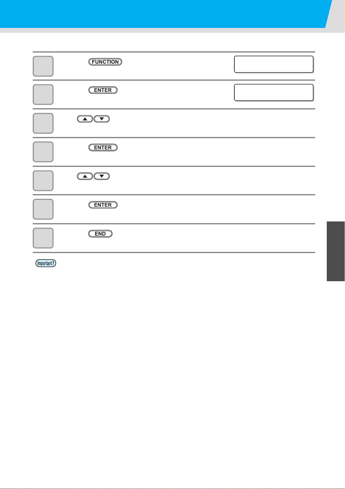
Other Settings
FUNCT I ON
SETUP [ ENT ]
SETUP
FEED COMP . [ ENT ]
Change the settings according to the types of use.
Press the key in LOCAL.
1
Press the key.
2
Press to select an item for setting.
3
• Select it, referring to P.3-2 “List of Functions”.
Press the key.
4
Press to select the setting value.
5
• Select it, referring to P.3-2 “List of Functions”.
1
6
7
Press the key.
1
Press the key several times to end the setting.
• The set value is retained even when the power is turned "OFF".
3
Convenient use
5
6
3-9
Page 80

Machine Settings
Common settings are functions for using this machine easily.
The following items can be set in Machine settings.
Item Set value Default Meaning
AUTO Power-off
MEDIA REMAIN
( P.3-12)
TIME
UNIT
KEY BUZZER
LANGUAGE
RESET
( P.3-18)
TEMP.
LENGTH
NONE/
10 ~ 600min
ON / OFF OFF
+4h ~ -20h
°C (Centigrade)
/°F (Fahrenheit)
mm / inch mm
OFF / ON ON
English
ニホンゴ
Deutsch
Français
Español
Italiano
Português
30min
Japan time
°C A unit for displaying temperature is set.
English Displayed language is changed.
When no operation has been performed
for the set time, the power supply is
automatically turned “OFF”.
You can control the remaining amount of
media.
Time difference is corrected.
A unit for displaying length and area is
set.
A buzzer sound when keys are pressed
is set.
All setting values are returned to the
status default.
3-10
Page 81
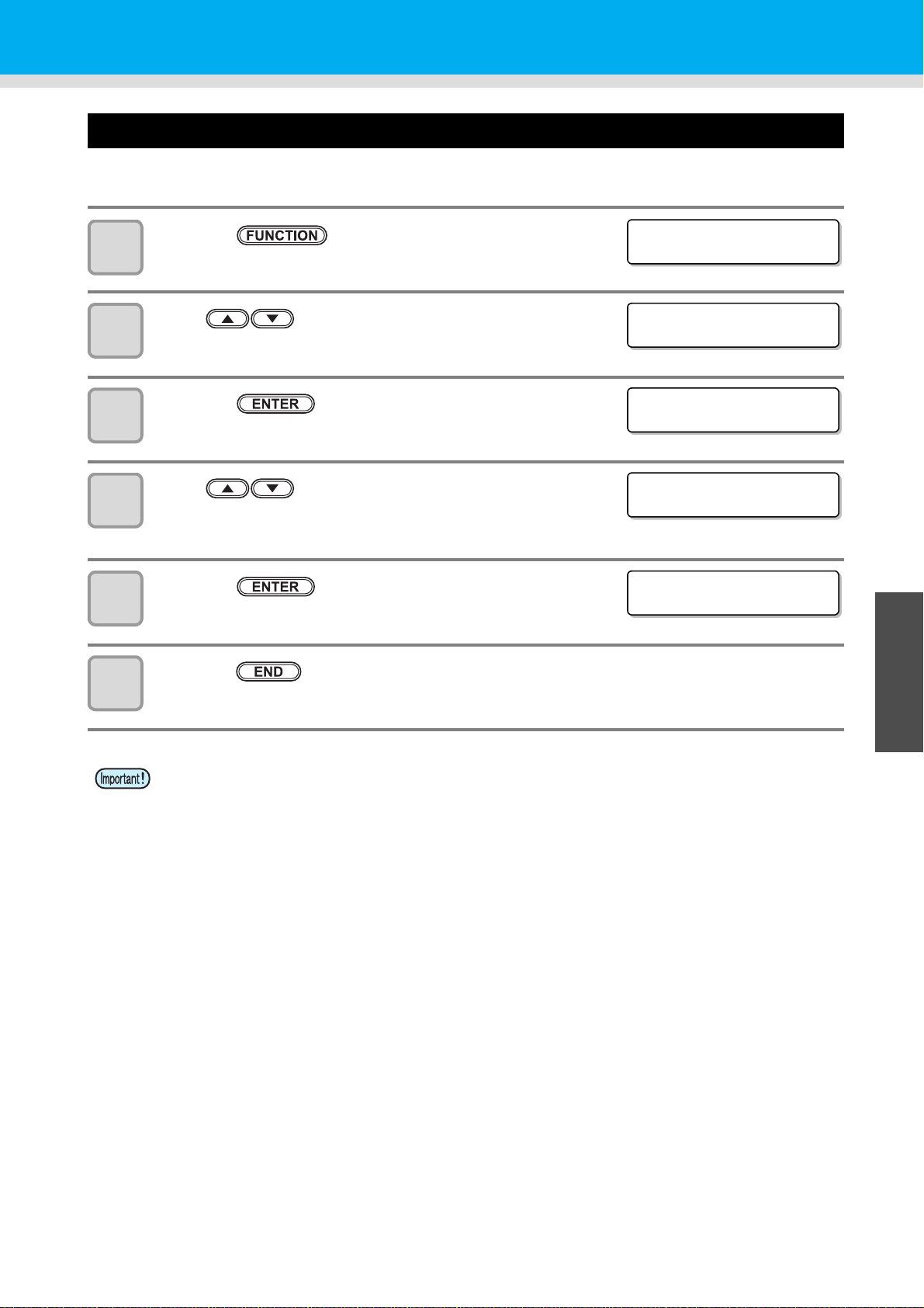
Machine Settings
FUNCT I ON
SETUP [ ENT ]
FUNCT I ON
MACH I NE SETU P [ E NT ]
AUTO Powe r - o f f
=30min
AUTO Powe r - o f f
=60min
MACH I NE SETU P
AUTO Powe r - o f f [ ENT ]
Setting a AUTO Power-off
When no operation has been performed for the set time, the power supply is automatically turned “OFF”.
Press the key in LOCAL.
1
Press to select [MACHINE SETUP].
2
3
4
5
6
Press the key twice.
Press to set time to turn OFF the power
supply.
• Set Value : none, 10 to 600min
Press the key.
Press the key several times to end the setting.
• If the machine received data from the PC in the auto-power-off status, the power supply is turned ON,
however, printing operation is not started automatically.
1
1
3
Convenient use
5
6
3-11
Page 82

Setting the Display of Media Residual
FUNCT I ON
SETUP [ ENT ]
FUNCT I ON
MACH I NE SETU P [ E NT ]
MACH I NE SETU P
AUTO Powe r - o f f [ ENT ]
MACH I NE SETU P
MED I A R EMA I N [ E N T ]
MED I A R EMA I N
:OFF
MED I A R EMA I N
:ON
MACH I NE SETU P
MED I A R EMA I N [ E N T ]
Whether the screen displays the remaining amount of a media is set.
When the media remaining amount
display is turned to "ON"
When the media remaining amount
display is turned to "OFF"
• The amount of a media that has been fed by the printing and jog keys is reflected in the remaining
amount of a media.
• The length of a media (initial value of the remaining amount) is entered when a roll media is
detected.( P.2-12)
• The setting configured here does not become effective unless media detection is performed after the
setting has been complete.
Press the key in LOCAL.
1
Press to select [MACHINE SETUP].
2
Press the key.
3
the remaining amount of a media is displayed in Remote.
(However, when a leaf media is used, the length of the media to be
printed is displayed.)
the remaining amount of a media is not displayed in the Remote.
4
5
6
7
8
Press to select [MEDIA REMAIN].
Press the key.
Press to select ON/OFF.
Press the key.
Press the key several times to end the setting.
3-12
Page 83
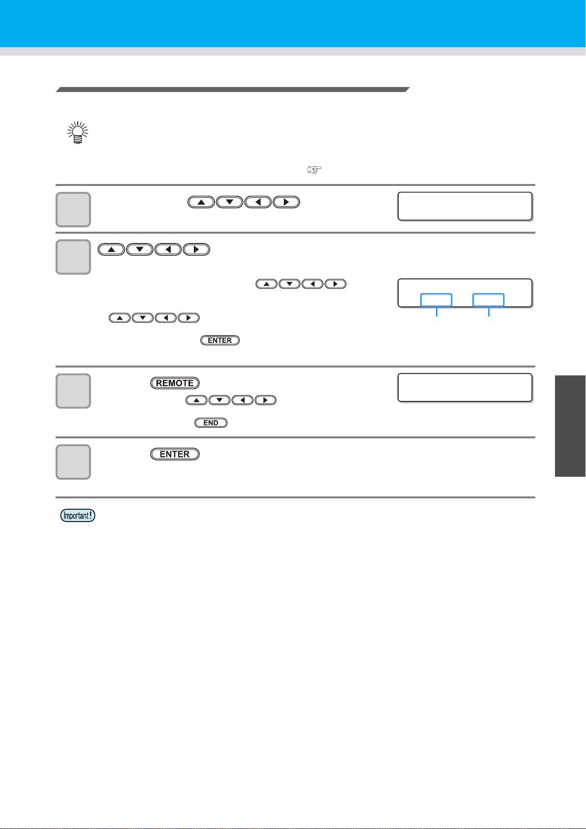
Printing the Remaining Amount of a Media
OR I G I N SE T UP
0.0 ----
OR I G I N SE T UP
0.0 0.0
Origin
(Length)
Origin
(Width)
MEDIA REMAIN PRINT
<ENT>
The present remaining amount of a media can be printed.
• Set "Remaining amount of a media to display" to "ON".
• When you replace the media you use now with another, it is recommended that you print the
remaining amount of the media on it.With the remaining amount of a media having been printed
beforehand, when you use the replaced media again, you can enter an accurate value in the screen
for entering the remaining amount of a media ( P.2-12) that appears after media detection.
In LOCAL, Press .
1
2
• LOCAL changes to the origin setting mode.
Press to set a light point of the LED pointer to the changing
position.
• Move the carriage and media with and set
the origin.
• When you do not change the origin, do not press
and proceed to Step 3.
Machine Settings
1
3
4
• When you press the key here, the origin is changed,
and the screen returns to LOCAL.
Press the key.
• When you press , the screen returns to
Step 2.
• When you press the key, the screen returns to LOCAL.
Press the key.
• The remaining amount of a media starts to be printed.
• When the printing has been completed, the screen returns to LOCAL.
• When the remaining amount of a media has been printed with the origin changed, the origin set here
is effective even when subsequent data are printed.
1
3
Convenient use
5
6
3-13
Page 84
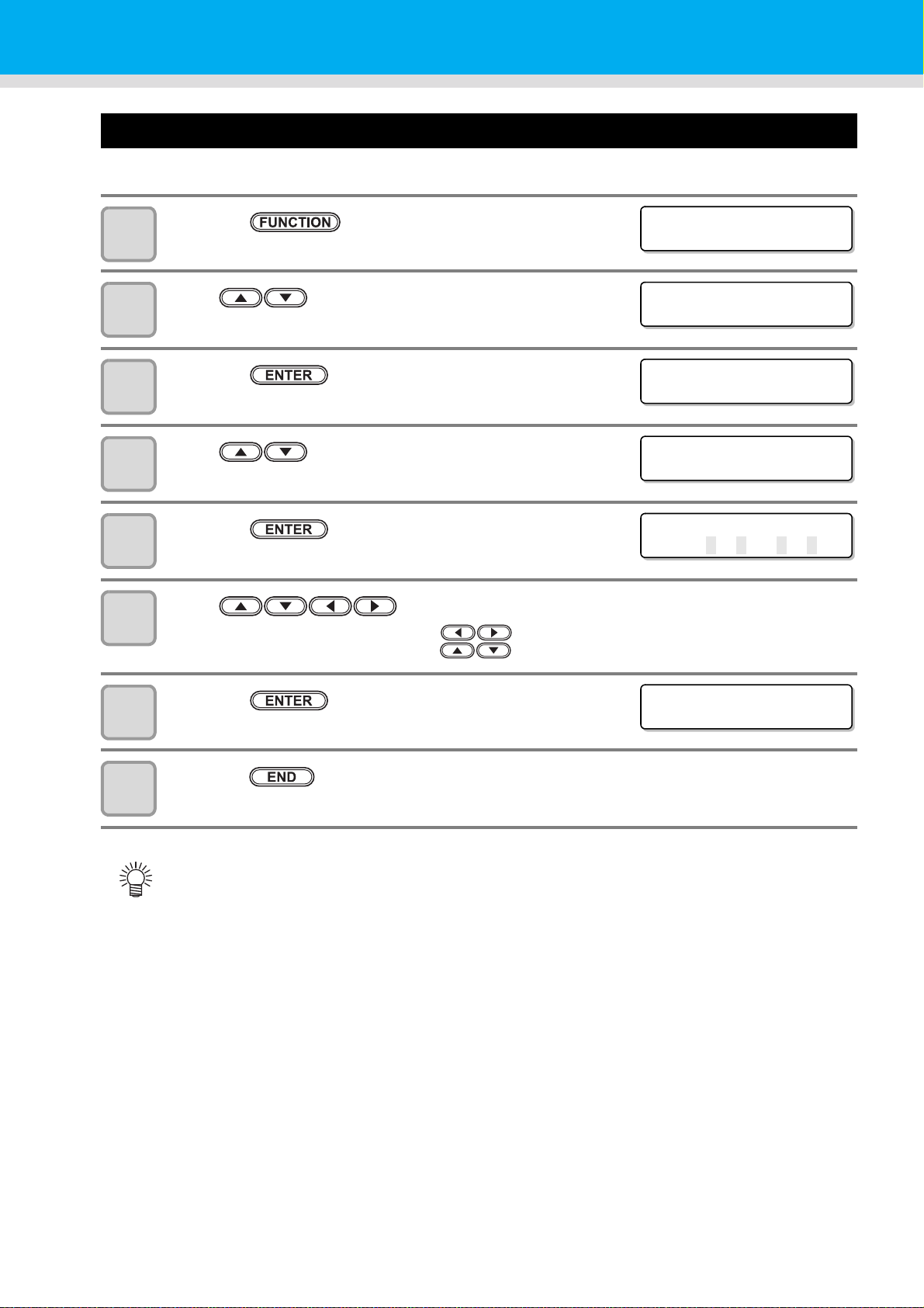
Setting Time
FUNCT I ON
SETUP [ ENT ]
FUNCT I ON
MACH I NE SETU P [ E NT ]
MACH I NE SETU P
AUTO Powe r - o f f [ ENT ]
MACH I NE SETU P
TIME [ENT]
TIME
2013 .1
0.0521:30:00
TIME
2013 .10.05 15 : 30:00
You can set time of your country (time difference).
Press the key in LOCAL.
1
Press to select [MACHINE SETUP].
2
Press the key.
3
Press to select [TIME].
4
Press the key.
5
6
7
8
Press to enter time.
Year/Month/Day/Time selecting:by the keys.
Year/Month/Day/Time inputting:by the keys.
Press the key.
• The entered date is displayed.
Press the key several times to end the setting.
• -20 hours to +4 hours can be set.
3-14
Page 85
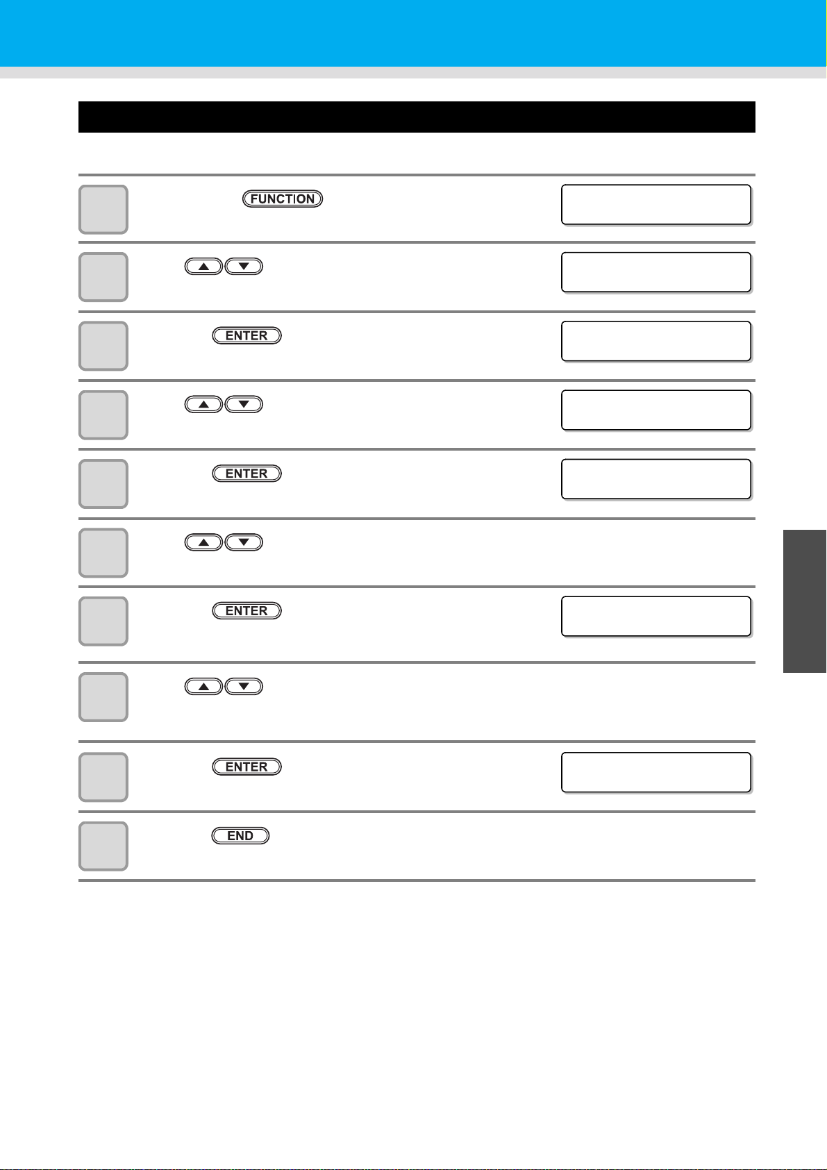
Setting Units
FUNCT I ON
SETUP [ ENT ]
FUNCT I ON
MACH I NE SETU P [ E NT ]
MACH I NE SETU P
AUTO Powe r - o f f [ ENT ]
MACH I NE SETU P
UN I T [ ENT ]
TEMP
: ° C
LENGTH
:mm
MACH I NE SETU P
UN I T [ ENT ]
Units used by this machine are set.
Press the key in LOCAL.
1
Press to select [MACHINE SETUP].
2
Press the key.
3
Press to select [UNIT].
4
Machine Settings
1
5
6
7
8
9
10
Press the key.
Press to select a unit of the temperature.
• Set value : °C / °F
Press the key.
Press to select a unit of the length.
• Set value : mm / inch
Press the key.
Press the key several times to end the setting.
1
3
Convenient use
5
6
3-15
Page 86
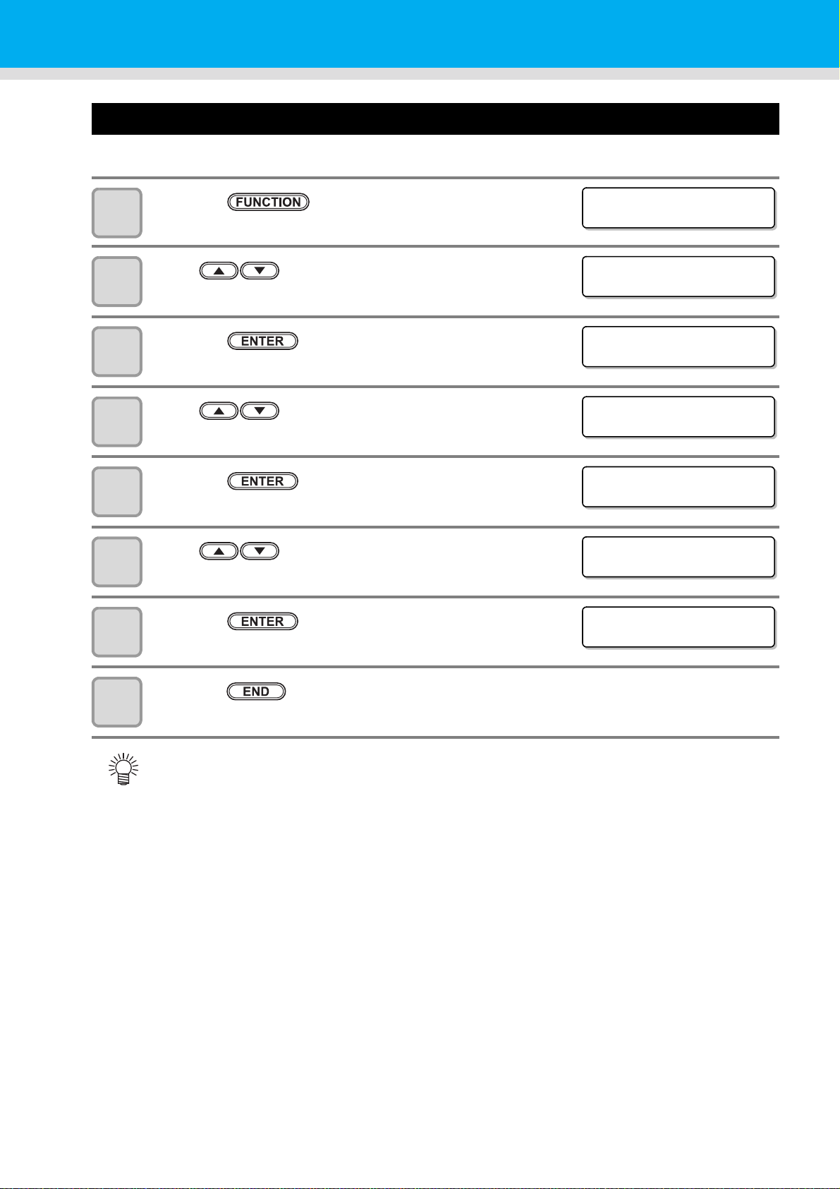
Setting a KEY BUZZER
FUNCT I ON
SETUP <ENT>
FUNCT I ON
MACH I NE SETU P [ E NT ]
MACH I NE SETU P
AUTO Powe r - o f f [ ENT ]
MACH I NE SETU P
KEY BUZZER [ ENT ]
KEY BUZZER
:ON
KEY BUZZER
:OFF
MACH I NE SETU P
KEY BUZZER [ ENT ]
You can turn off the buzzer sound when pressing the key.
Press the key in LOCAL.
1
Press to select [MACHINE SETUP].
2
Press the key.
3
Press to select [KEY BUZZER].
4
Press the key.
5
6
7
8
Press to select ON/OFF.
Press the key.
Press the key several times to end the setting.
• When the key buzzer is set to "OFF", the buzzer sound for errors, warnings, operation completion,
etc. cannot be shut off.
3-16
Page 87

Setting a LANGUAGE
FUNCT I ON
SETUP [ ENT ]
FUNCT I ON
MACH I NE SETU P [ E NT ]
MACH I NE SETU P
AUTO Powe r - o f f [ ENT ]
MACH I NE SETU P
LANGUAGE [ ENT ]
LANGUAGE
:Engl i sh
LANGUAGE
:
ニホン コ ゛
MACH I NE SETU P
LANGUAGE [ ENT ]
You can change the displayed language.
Press the key in LOCAL.
1
Press to select [MACHINE SETUP].
2
Press the key.
3
Press to select [LANGUAGE].
4
Machine Settings
1
5
6
7
8
Press the key.
1
Press to select language.
• Set Value:ニホンゴ / English / Deutsch / Français / Español /
Italiano / Português
Press the key.
3
Convenient use
Press the key several times to end the setting.
5
6
3-17
Page 88

Initializing the Settings
FUNCT I ON
SETUP [ ENT ]
FUNCT I ON
MACH I NE SETU P [ E NT ]
MACH I NE SETU P
AUTO Powe r - o f f [ ENT ]
MACH I NE SETU P
RESET [ ENT ]
RESET ALL SETT I NG
OK? [ ENT ]
RESET
EXECUTE [ ENT ]
You can return the setting of “SETUP”, “MAINTENANCE” and “MACHINE SETUP” to the status before
shipment.
Press the key in LOCAL.
1
Press to select [MACHINE SETUP].
2
Press the key.
3
Press to select [RESET].
4
5
6
7
Press the key.
Press the key.
• The already configured settings are initialized.
Press the key several times to end the setting.
• The initial setting screed is displayed. (LANGUAGE/TIME)
3-18
Page 89

Confirming Machine Information
FUNCT I ON
SETUP [ ENT ]
FUNCT I ON
INFORMAT ION [ENT ]
INFORMAT ION
USAGE [ ENT ]
The information of this machine can be confirmed.
The following items can be confirmed as machine information.
Item Description
WIPING
WASTE INK
BOTTLE
USAGE
VERSION This displays the firmware version of the machine.
LIST This allows you to print the settings of the machine.
Ink REPL. Report This prints ink history of this machine.
Displaying the Information
PRINT LENGTH
PRINT AREA
USE TIME
FILTER(White)
The information of this machine can be confirmed.
1
1
2
3
4
Press the key in LOCAL.
Press to select [INFORMATION].
Press the key.
Press to select [USAGE].
1
3
Convenient use
5
6
3-19
Page 90

5
WI P I NG
=0
WA S T E I N K B O T T L E
=0%
PR I NT LENGTH
=0m
PR I NT AREA
=0m
2
USE T I ME
=0h
FILTER(Whi te)
=0d
WI P I NG
RESET ? [ ENT ]
MAINT.
FILTER(Whi te)
RESET ? [ ENT ]
MAINT.
Press the key.
• The wiping Information is displayed.
• Every time when you press the key, the next machine information is displayed sequentially.
WIPING
Displays wiping
information.
PRINT LENGTH
Displays printed
length up to now.
USE TIME
Displays used time
information of
machine.
• When you reset the used count of the wiper, press the key
while WIPING is displayed.
When you press the key, the number of wipings is reset.
• When you reset the used count of the wiper, press the key
while WHITE INK FILTER is displayed.
When you press the key, the used time of white ink filter is
reset.
WASTE INK BOTTLE
Displays waste ink
bottle information.
PRINT AREA
Displays printed
area up to now.
FILTER(white)
Displays used time
up to now.
3-20
Page 91
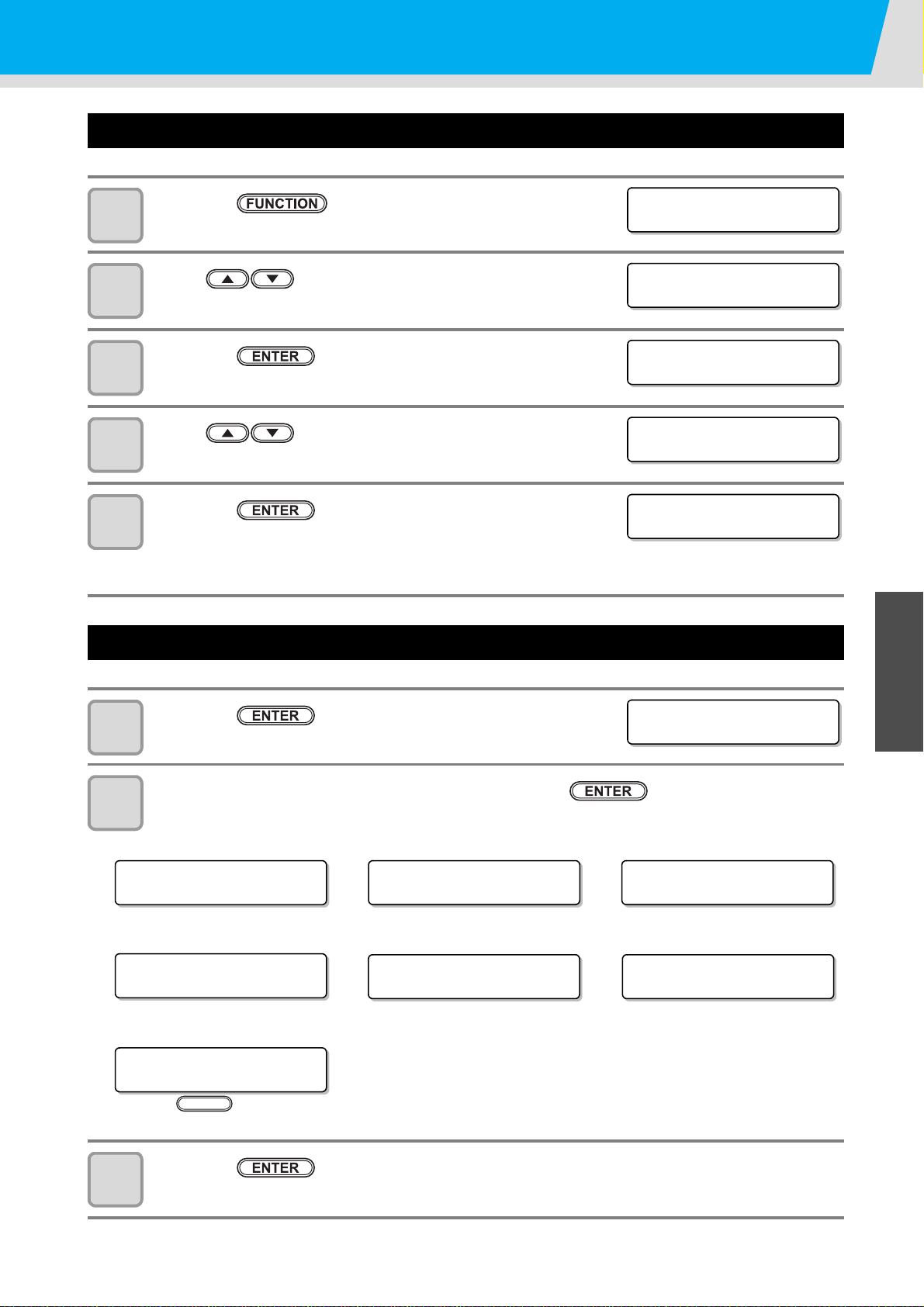
Confirming Machine Information
FUNCT I ON
SETUP [ ENT ]
FUNCT I ON
INFORMAT ION [ENT ]
INFORMAT ION
USAGE [ ENT ]
INFORMAT ION
VERS I ON [ ENT ]
V1 . 00
MR L - I I I V 1 . 8 0
***INK MMCCYYKK
REMA IN 99999999
***INK MMCCYYKK
REMA IN 99999999
Remaining amount of ink
NON I NK I C
MMCCYYKK
WA R N I N G
Rep l ace WI PER[MNT ]
Warning (when warning occurs)
MED I A WI DTH
= 1000mm
Media width
SER I AL No .
:********
Serial No.
Error (when ink error occurs)
V1 . 00
MR L - I I I V 1 . 8 0
Versio n
NOZ Z L E RECOVERY
CONF I RM DETA I LS [MNT ]
RECOVERY NOZZLE
Press the key and confim the description
MAINT.
Check such as the machine version information
Press the key in LOCAL.
1
Press to select [INFORMATION].
2
Press the key.
3
Press to select a type of information.
4
Press the key.
5
• When [VERSION] is selected, the version Information is displayed.
• When [List] is selected, the setting contents of the machine are printed.
• When [Ink REPL. Report] is selected, ink history of this machine are printed.
1
1
Displaying the Information of this machine
Press the key in LOCAL.
1
The information is displayed sequentially with the key .
2
• The information shown on the below appear.
3
Convenient use
5
Press the key to return to LOCAL.
3
6
3-21
Page 92

3-22
Page 93

Chapter 4
Maintenance
This chapter
describes the items required to use this machine more comfortably, which are the
methods for the daily care, the maintenance of the ink unit etc.
Maintenance .................................................4-2
Precautions for Maintenance ...................... 4-2
About Cleaning Fluid ................................... 4-2
Cleaning the Exterior Surfaces ................... 4-3
Cleaning the Media Transfer Surface ......... 4-3
Cleaning of after heater cover and pre
heater cover ................................................ 4-3
Cleaning the Media Sensor ......................... 4-4
Cleaning the Media Holder .......................... 4-4
Maintaining the Capping Station ...................4-5
Cleaning the Wiper and Cap ....................... 4-5
Washing the Ink Discharge Passage
(DISWAY WASH) ........................................ 4-8
When the Machine Is Not Used for a
Long Time (CUSTODY WASH) .................. 4-9
Cleaning the Head and the Area around It
(every day) ..................................................4-13
Replacing method of absorber kit ...............4-15
When Nozzle Clogging Cannot Be Solved ..4-17
Washing of Head nozzle ............................4-17
Washing nozzle surface .............................4-20
Alternative nozzles for printing, when
nozzles missing can not be improved ........ 4-22
Automatic Maintenance Function ................4-25
Setting the Refreshing Intervals .................4-25
Setting the Cleaning Intervals ....................4-26
Setting the Cleaning Intervals ....................4-27
Replacing consumables ..............................4-28
Replacing the wiper ...................................4-28
If a Waste Ink Bottle Confirmation
Message Appears ......................................4-29
Replacing the Cutter Blade ........................4-32
Replacing the white ink filter ......................4-34
When white ink filter becomes required to
be replaced ................................................4-34
Page 94

Maintenance
Maintain the machine regularly or as necessary so that its accuracy will be maintained and it can continue to be
used for a long time.
Precautions for Maintenance
Pay attention to the following items when maintaining this machine.
• When using Cleaning Fluid for maintenance, be sure to wear the supplied protective glasses.
• The ink contains organic solvent.When cleaning the machine, be sure to wear gloves so that
no ink will make direct contact with your skin.
• Never disassemble the machine.Disassembling it can result in electric shock hazards or
damage to the machine.
Before maintenance, be sure to turn off the power switch and main power switch, and unplug
the power cable;otherwise, an unexpected accident may occur.
• Prevent moisture from entering the machine.Moisture inside the machine can cause electric
shock hazards or damage to the machine.
• To ensure stable ink jetting, it is necessary for the machine to eject a small amount of ink
(flushing) regularly when a printing (outputting) operation has not been performed for a long
time.
• When the machine is not to be used for a long time, turn off only the power switch on the front
side, leave the main power switch at the side turned ON (in the position of | ), and leave the
power cable connected.
• If organic solvent ink is mixed with water or alcohol, coagulation is generated.
Do not wipe the nozzle face of the heads, wiper, caps, etc. with water or alcohol.Doing so can
cause nozzle clogging or machine failure.
• Do not use benzene, thinner, or any chemical agent containing an abrasive.Such materials
can deteriorate or deform the surface of the cover.
• Do not apply a lubricant, etc. to any parts inside the machine. Doing so can cause printing
failure.
• Be careful that the Cleaning Fluid, ink, etc. not to stick to the cover because this may cause
the surface of the cover to deteriorate or deform.
About Cleaning Fluid
Use the cleaning fluid that is recommended by this company.
4-2
Page 95

Cleaning the Exterior Surfaces
After heater cover
Pre heater cover
When the exterior surfaces of the machine are stained,
dampen a soft cloth with water or a neutral detergent
diluted with water, squeeze it, and wipe the surfaces
with the cloth.
Cleaning the Media Transfer Surface
The Media Transfer Surface easily gets dirty with lint,
paper dust, etc. generated when a media is cut.
Wipe off conspicuous stains with a soft-hair brush, a dry
cloth, a paper towel, etc.
Maintenance
1
• When the Media Transfer Surface is
stained with ink, wipe it off with a paper
towel containing a small amount of
Cleaning Fluid for maintenance.
• Before cleaning the Media Transfer Surface, make sure that the Media Transfer Surface has cooled
adequately.
• Because dust and dirt are easily accumulated in the slots for holding a media and cutting paper (cutter
slot), be sure to clean these parts carefully.
Cleaning of after heater cover and pre heater cover
The after heater cover and the pre heater cover are easy to be dirty because of the powder of the medium etc.
If it shows dirt, wipe it with a soft cloth soaked in water or waterish mild detergent and wrung.
1
1
4
Routine Maintenance
4-3
Page 96

Maintenance
Media sensor
Media sensor
The backside of the machine The lower surface of the head
Media press
Cleaning the Media Sensor
The media sensors are located on the Media Transfer Surface in the backside and the bottom surface of the
head. When the sensor is covered with dust, etc., it may cause false detection of media.
Using a cotton swab, remove the dust, etc. accumulated on the surface of the sensor.
When cleaning the sensor on the lower surface of the head is cleaned, move the carriage to the left end by the
operations of step 1 of P.4-13 “Cleaning the Head and the Area around It (every day)”, and then clean it.
Cleaning the Media Holder
When the media holder is covered with lint, dust, etc., a media cannot be fed normally during printing or dust
sticks to the nozzles, which may result in abnormal printing.
Clean the media holder regularly.
4-4
Page 97

Maintaining the Capping Station
WI PER CLEAN I NG
[MNT]
MAINT.
MAINT.
Reference for cleaning
Top edge of the film
CARR I AGE OUT
[ENT]
MAINT.
MOVE P OS I T I ON
:STATION MAINT.
MOVE P OS I T I ON
:STATION MAINT.
Maintain the ink cap, wiper, etc. located in the capping station. (SATION MAINT.)
• To keep the nozzle status normal, perform wiper cleaning
frequently.
• The right message is displayed periodically in LOCAL. When
you press the key, it moves to cleaning function.
The ink cap and wiper function as follows.
• Wiper : It wipes off ink sticking to the head nozzles.
• Ink cap : It prevents the head nozzles from clogging due to dryness.
As the machine is used repeatedly, the wiper and ink cap gradually become dirty with ink, dust, etc.
If nozzle missing cannot be corrected even after head cleaning ( P.2-22) has been performed, Clean this
machine using the cleaning supplies that are recommended by this company.
Tools required for Maintenance
• Be sure to wear the supplied goggles and gloves when maintaining the capping
station.Otherwise, you may get ink in your eyes.
• Do not move the carriage out of the capping station by hand.When it is desirable to move the
carriage, press the key to execute the carriage-out. ( P.4-5Steps 1 to 2)
• Maintenance kit • Gloves
• Clean stick • Goggles
Cleaning the Wiper and Cap
Ink, dust, or paper waste is pooled on the wiper. To keep stable printing quality, wash the wiper and cap at the
end of the day.
• Further, in the cases as explained below, replace the wiper with the new one.( P.4-28)
Even if you clean the wiper enough, nozzle clogging etc. occurs frequently
When the wiper is deformed
When the stuck ink can not be wiped off
When the warning for wiper replacement is indicated
• When cleaning the wiper, be careful that lint from the clean stick or kimwipe® does not get left on the
wiper.Remaining lint may cause image quality to deteriorate.
• Clean the wiper completely until the stained ink on the top
edge of the wiper film is washed away after soaking the wiper
in the Cleaning Fluid for 1-24 hours. It is recommended to
prepare two or more wipers and use them alternately.
• If cleaning of the wiper is not enough, it may cause nozzle
clogging.
• Do not wash the wiper with other than the Kimwipe®.
Otherwise, lint may remain on the wiper.
1
1
1
4
Routine Maintenance
1
2
3
Press the key in LOCAL.
Press the key.
Press to select [STATION MAINT.].
4-5
Page 98
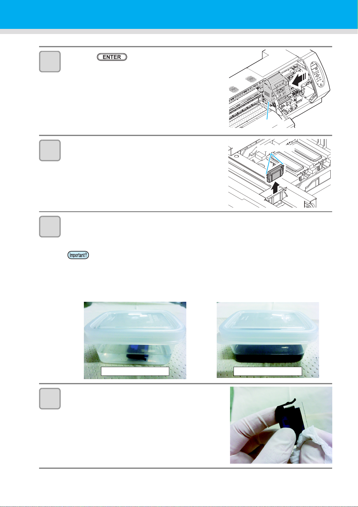
4
Carriage
Projection
At the start of immersion
At the end of immersion
5
6
Press the key.
• The carriage moves to the maintenance position.
• If the carriage is not covered by the ink cap for a long period
of time, the nozzle face of the head may get dry and clogged,
resulting in white lines being left in the printed image.
• The buzzer sounds periodically while the carriage is out of the
capping station. The buzzer sounds at shorter interval when
the print heater temperature is high.
Open the right maintenance cover cover then
remove the wiper.
• Pull out the wiper by holding the protrusions at its both ends.
Put the wiper that you used for one day into a provided case or solvent-resistancecovered-container (glass, earthenware, etc.) and pour Cleaning Fluid.
• Time to immerse the wiper shall be for 1 to 24 hours.
7
• If you leave the wiper immersed in Cleaning Fluid too long, the wiper may be deformed.
• Dispose the Cleaning Fluid for soaking the wiper if it gets dirty. (As a guide, replace it in a
week). Regarding disposal of unused Cleaning Fluid, please ask Industrial waste disposer
and pursuant to the regulations of your district.
• For case for immersing the wiper, please use provided case or solvent-resistance-coveredcontainer. In case that you want to immerse the wiper by using your resin case, please
make sure to test whether there are no problems such as case deformation before you try.
Take out the wiper and remove ink blot etc. with a
Kimwipe®.
• Wipe off well so that any lint etc. do not remain on the top
edge of the wiper film.
4-6
Page 99

8
Clean
Projection
Space below the wiper guide Space between the wiper
slider and ink guard W
Wiper guide
Wiper guide
Ink guard W
Enlarged view of the Wiper Slider
and Ink Guard W
Do not clean this part
Clean this part along the rail
9
Maintaining the Capping Station
Clean the wiper slider.
• Wipe off the ink sticking of the figure with a clean stick dipped
in Cleaning Fluid for maintenance.
Wipe off so that Cleaning Fluid for maintenance will not
remain.
Set the wiper at the original position.
• Insert the wiper by holding both ends of the wiper.
1
10
Clean the area around the wiper.
• Dip the clean stick in the cleaning liquid for maintenance, and wipe the space below the wiper guide,
and the space between the wiper slider and ink guard W.
1
1
4
Routine Maintenance
4-7
Page 100

11
Cap rubber
Cap rubber cover
After cleaningBefore cleaning
Close cover
COMP LET ED [ EN T ]
MAINT.
MAINT.
MAINT.
CARR I AGE OUT
[ENT]
MAINT.
DISWAY WASH
[ENT]
12
13
Clean the cap rubber and cap rubber cover.
• Wipe off the ink sticking to the cap rubber and cap rubber
cover with a clean stick dipped in Cleaning Fluid for
maintenance. (Wipe off so that you can see blue color of the
cap rubber.) Wipe off so that Cleaning Fluid for maintenance
will not remain.
Press the key after the cleaning.
Close the right maintenance cover then press the
key.
• After its initial operation, the machine returns to step1.
Performing the station maintenance without key
You can select station maintenance by using the key in the Local without pressing the key.
Press the
key in Local.
Press to
select [MAINTENANCE].
Press the key twice.
• It becomes the same condition as the
key is pressed from Local.
Washing the Ink Discharge Passage (DISWAY WASH)
Wash the ink discharge passage regularly(about once a week) to prevent the head nozzles from clogging due
to ink coagulation inside the passage.
Press the key in LOCAL.
1
Press to select [DISWAY WASH].
2
4-8
 Loading...