

Page 1

Model Kr-P2
Machine Code: M047
Field Service Manual
15 December,2009
Page 2

Page 3

Safety Notices
Important Safety Notices
Prevention of Physical Injury
1. Before disassembling or assembling parts of the machine and peripherals, make sure that the machine
power cord is unplugged.
2. The wall outlet should be near the machine and easily accessible.
3. If any adjustment or operation check has to be made with exterior covers off or open while the main
switch is turned on, keep hands away from electrified or mechanically driven components.
4. The machine drives some of its components when it completes the warm-up period. Be careful to keep
hands away from the mechanical and electrical components as the machine starts operation.
5. The inside and the metal parts of the fusing unit become extremely hot while the machine is operating.
Be careful to avoid touching those components with your bare hands.
Health Safety Conditions
Toner is non-toxic, but if you get either of them in your eyes by accident, it may cause temporary eye
discomfort. Try to remove with eye drops or flush with water as first aid. If unsuccessful, get medical attention.
Observance of Electrical Safety Standards
The machine and its peripherals must be serviced by a customer service representative who has completed
the training course on those models.
• The Controller board on this machine contains a lithium battery. The danger of explosion exists if a
battery of this type is incorrectly replaced. Replace only with the same or an equivalent type
recommended by the manufacturer. Discard batteries in accordance with the manufacturer's
instructions and local regulations.
Safety and Ecological Notes for Disposal
1. Do not incinerate toner bottles or used toner. Toner dust may ignite suddenly when exposed to an
open flame.
2. Dispose
in accordance with local regulations. (These are non-toxic supplies.)
of used toner, the maintenance unit which includes developer or the organic photoconductor
1
Page 4

3. Dispose of replaced parts in accordance with local regulations.
prevent a fire or explosion, keep the machine away from flammable liquids, gases, and aerosols.
• To
A fire or an explosion might occur.
Handling Toner
• Work carefully when removing paper jams or replacing toner bottles or cartridges to avoid spilling
toner on clothing or the hands.
toner is inhaled, immediately gargle with large amounts of cold water and move to a well ventilated
• If
location. If there are signs of irritation or other problems, seek medical attention.
• If toner gets on the skin, wash immediately with soap and cold running water.
• If toner gets into the eyes, flush the eyes with cold running water or eye wash. If there are signs of
irritation or other problems, seek medical attention.
• If toner is swallowed, drink a large amount of cold water to dilute the ingested toner. If there are signs
of any problem, seek medical attention.
• If toner spills on clothing, wash the affected area immediately with soap and cold water. Never use
hot water! Hot water can cause toner to set and permanently stain fabric.
• Always store toner and developer supplies such as toner and developer packages, cartridges, and
bottles (including used toner and empty bottles and cartridges) out of the reach of children.
• Always store fresh toner supplies or empty bottles or cartridges in a cool, dry location that is not
exposed to direct sunlight.
Laser Safety
The Center for Devices and Radiological Health (CDRH) prohibits the repair of laser-based optical units
in the field. The optical housing unit can only be repaired in a factory or at a location with the requisite
equipment. The laser subsystem is replaceable in the field by a qualified Customer Engineer. The laser
chassis is not repairable in the field. Customer engineers are therefore directed to return all chassis and
laser subsystems to the factory or service depot when replacement of the optical subsystem is required.
• Use
of controls, or adjustment, or performance of procedures other than those specified in this manual
may result in hazardous radiation exposure.
WARNING
2
Page 5
WARNING:
Turn off the main switch before attempting any of the procedures in the Laser Unit section. Laser beams
can seriously damage your eyes.
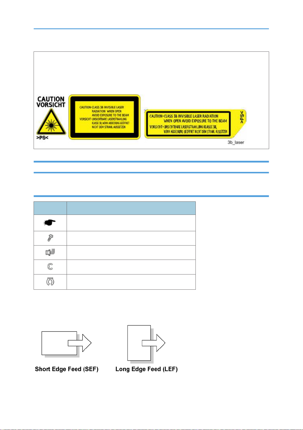
CAUTION MARKING:
Conventions and Trademarks
Conventions
Symbol What it means
Refer to section number
Screw
Connector
E-ring
C-ring
The following notations are used in text to describe the direction of paper feed: lengthwise and sideways.
The annotations "SEF" and "LEF" denote "Short Edge Feed" and "Long Edge Feed". (The arrows indicate
the direction of paper feed.)
3
Page 6

Trademarks
Microsoft®, Windows®, and MS-DOS® are registered trademarks of Microsoft Corporation in the United
States and /or other countries.
PostScript® is a registered trademark of Adobe Systems, Incorporated.
PCL® is a registered trademark of Hewlett-Packard Company.
Ethernet® is a registered trademark of Xerox Corporation.
PowerPC® is a registered trademark of International Business Machines Corporation.
Other product names used herein are for identification purposes only and may be trademarks of their
respective companies. We disclaim any and all rights involved with those marks.
This manual uses several symbols and some simple abbreviations.
4
Page 7

TABLE OF CONTENTS
Safety Notices.....................................................................................................................................................1
Important Safety Notices...............................................................................................................................1
Laser Safety.....................................................................................................................................................
Conventions and Trademarks........................................................................................................................3
1. Product Information
Specifications......................................................................................................................................................9
Overview..........................................................................................................................................................10
Mechanical Component Layout ................................................................................................................10
Paper Path....................................................................................................................................................11
Machine Configuration....................................................................................................................................
Model M047...............................................................................................................................................13
13
2. Installation
Installation Requirements.................................................................................................................................15
Environment..................................................................................................................................................15
Machine Level..............................................................................................................................................15
Machine Space Requirement ....................................................................................................................16
Power Supply...............................................................................................................................................16
Machine Installation.........................................................................................................................................
Main Unit and Option Unit.........................................................................................................................17
17
2
Printer Option...............................................................................................................................................17
SD Card Appli Move...................................................................................................................................17
3. Preventive Maintenance
User Maintenance............................................................................................................................................21
Service Maintenance.......................................................................................................................................22
Main..............................................................................................................................................................
Paper Feed Unit (Option)............................................................................................................................23
22
4. Replacement and Adjustment
General.............................................................................................................................................................25
Precautions on Disassembly........................................................................................................................25
Releasing Plastic Latches.............................................................................................................................26
After Servicing the Machine........................................................................................................................
Special Tools....................................................................................................................................................28
Exterior Covers.................................................................................................................................................29
27
5
Page 8

Operation Panel...........................................................................................................................................29
Rear Cover...................................................................................................................................................30
Upper Cover................................................................................................................................................30
By-pass Tray.................................................................................................................................................30
Left Cover......................................................................................................................................................32
Front Door.....................................................................................................................................................32
Right Cover ..................................................................................................................................................33
Laser Unit..........................................................................................................................................................35
Caution Decal Location ..............................................................................................................................35
Polygon Mirror Motor ................................................................................................................................36
Laser Unit......................................................................................................................................................36
Laser Diode Unit ..........................................................................................................................................38
Laser Beam Pitch Adjustment ......................................................................................................................39
Image Transfer..................................................................................................................................................41
Transfer Roller .............................................................................................................................................41
Toner End Sensor.........................................................................................................................................41
Fusing................................................................................................................................................................43
Fusing Unit....................................................................................................................................................43
Hot Roller and Fusing Lamp........................................................................................................................43
Pressure Roller..............................................................................................................................................47
Thermistor and Thermostat..........................................................................................................................49
Hot Roller Strippers......................................................................................................................................51
Paper Feed........................................................................................................................................................53
Paper Feed Roller .......................................................................................................................................53
Friction Pad ..................................................................................................................................................53
Paper End Sensor.........................................................................................................................................54
Remaining Paper Sensors............................................................................................................................55
By-pass Feed ...................................................................................................................................................56
By-pass Feed Unit........................................................................................................................................56
By-pass Feed Roller.....................................................................................................................................56
By-pass Friction Pad....................................................................................................................................57
By-pass Paper Set Sensor...........................................................................................................................59
Paper Exit .........................................................................................................................................................61
6
Page 9

Paper Exit Sensor.........................................................................................................................................61
Overflow Sensor..........................................................................................................................................61
Paper Exit Unit .............................................................................................................................................61
Fusing Exit Sensor........................................................................................................................................62
Electrical Components.....................................................................................................................................64
Printer Controller Board...............................................................................................................................64
Engine Board................................................................................................................................................64
Main Motor..................................................................................................................................................65
Relay Clutch.................................................................................................................................................66
Paper Feed Clutch.......................................................................................................................................66
Registration Clutch.......................................................................................................................................68
Registration Sensor......................................................................................................................................68
Power Supply Board and High Voltage Supply Board............................................................................69
Fusing Pressure Sensor................................................................................................................................71
Fusing Fan.....................................................................................................................................................72
PSU Fan........................................................................................................................................................72
Image Adjustment.............................................................................................................................................74
Registration Adjustment ..............................................................................................................................74
Parallelogram Image Adjustment...............................................................................................................74
5. System Maintenance Reference
Service Program Mode....................................................................................................................................77
SP Tables......................................................................................................................................................77
Inputting a Value or Setting for a Service Program...................................................................................77
Exiting Service Mode..................................................................................................................................78
Updating the Firmware....................................................................................................................................79
Type of Firmware.........................................................................................................................................79
Precautions...................................................................................................................................................79
Machine Firmware Update.........................................................................................................................80
Error Recovery..............................................................................................................................................81
Power-On Self Tests ........................................................................................................................................83
Dip Switches.....................................................................................................................................................84
Controller Board..........................................................................................................................................84
7
Page 10

6. Troubleshooting
Service Call Conditions...................................................................................................................................85
Electrical Component Defects.........................................................................................................................86
Sensors..........................................................................................................................................................86
Switches........................................................................................................................................................87
Blown Fuse Conditions................................................................................................................................88
LEDs...............................................................................................................................................................88
7. Energy Saving
Energy Save......................................................................................................................................................89
Energy Saver Modes...................................................................................................................................89
Paper Save.......................................................................................................................................................91
Effectiveness of Duplex/Combine Function...............................................................................................91
INDEX.............................................................................................................................................................95
8
Page 11

1. Product Information
1
Specifications
See "Appendices" for the "General Specifications".
9
Page 12
1. Product Information
1
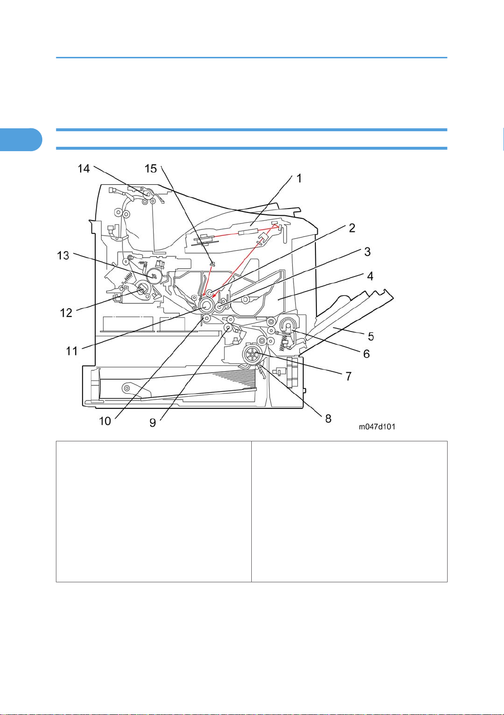
Overview
Mechanical Component Layout
1: Laser unit
9: Registration roller
2: Charge roller
10: Transfer roller
3: Development roller
11: Drum
4: Cartridge (AIO-type)
12: Pressure roller
5: By-pass feed tray
13: Hot roller
6: By-pass feed roller
14: Paper exit roller
7: Paper feed roller
15: Quenching lamp
8: Friction pad
10
Page 13
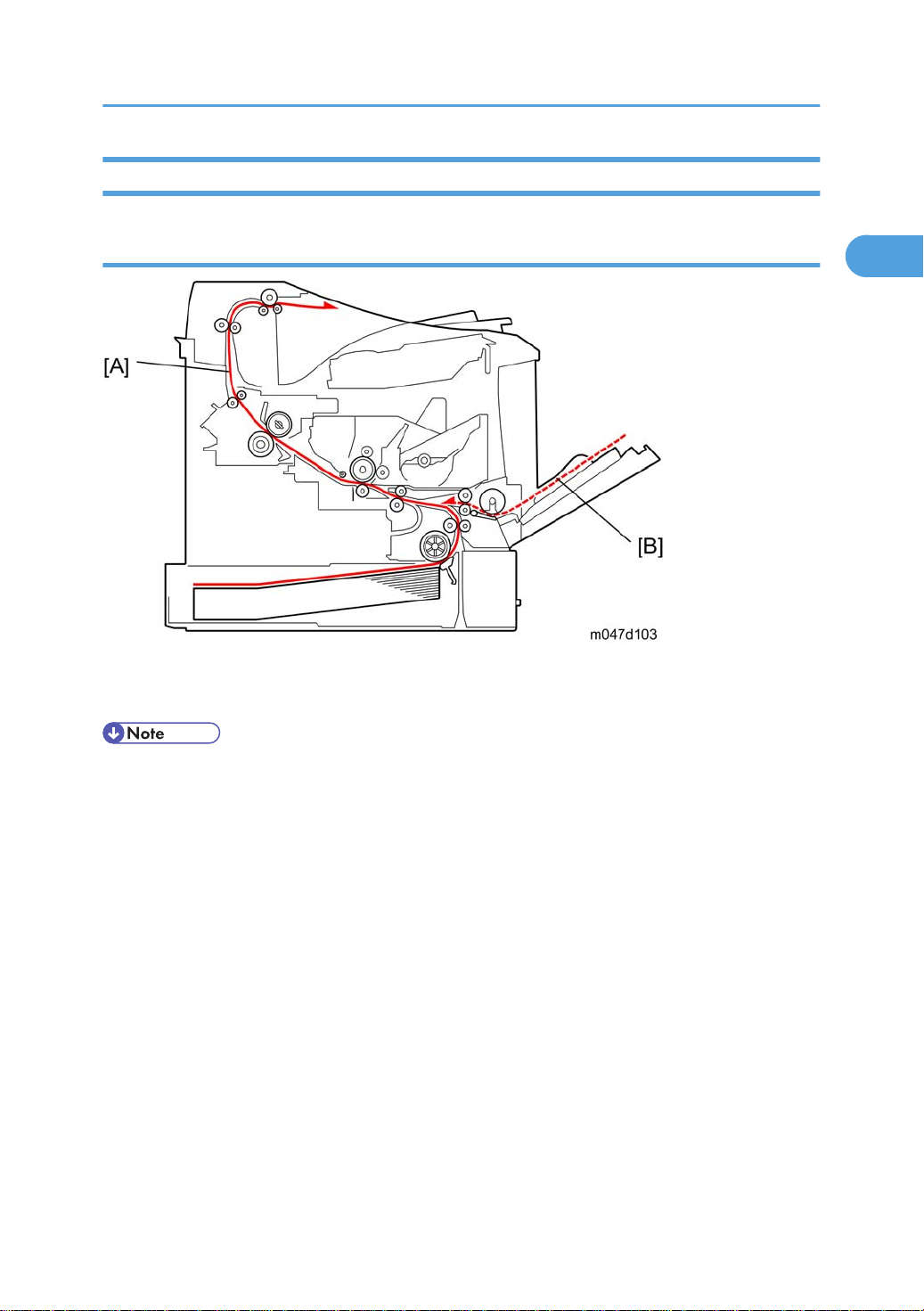
Paper Path
1
Printer
Overview
[A]: Paper path from the paper tray (main)
[B]: Paper path from the by-pass tray (main)
• If both optional paper tray units are installed, the envelope feeder must go in the top tray.
11
Page 14
1. Product Information
1
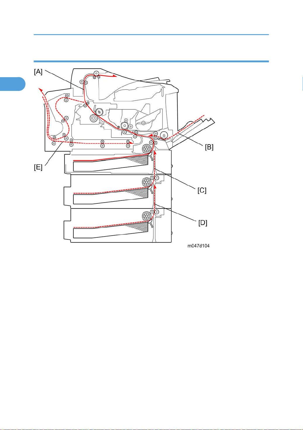
Printer with optional units
[A]: Paper path from the paper tray (main)
[B]: Paper path from the by-pass tray (main)
[C]: Paper path from the paper tray 2 (option)
[D]: Paper path from the paper tray 3 (option)
[E]: Paper path from the duplex unit (option)
12
Page 15
Machine Configuration
1
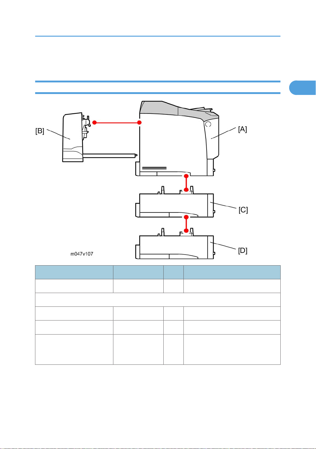
Model M047
Machine Configuration
Item Machine Code No. Remarks
Main Unit M047 A NIB is standard.
Optional Units
Duplex Unit G806 B
Paper Tray Unit M374 C, D Up to two tray units can be installed.
If both optional paper trays are
Envelope Feeder G807 C
installed, the envelope feeder must go
in the top tray.
13
Page 16

1. Product Information
1
14
Page 17

2. Installation
2
Installation Requirements
Environment
• This machine, which uses high voltage power sources, can generate ozone gas. High ozone density
is harmful to human health. Therefore, the machine must be installed in a well-ventilated room.
1. Temperature Range: 10°C to 32°C (50°F to 89.6°F)
2. Humidity Range: 15 % to 89 % RH
3. Ambient Illumination: Less than 2,000 lux (do not expose to direct sunlight).
4. Ventilation: 3 times/hr/person
5. Avoid areas that are exposed to sudden temperature changes. This includes:
• Areas directly exposed to cool air from an air conditioner.
• Areas directly exposed to heat from a heater.
6. Do not install this machine in an area where it will be exposed to corrosive gases.
7. Do not install the machine at locations over 2,000 m (6,562 ft.) above sea level.
8. Put the machine on a strong and level base. Inclination on any side should not exceed 5 mm.
9. Do not put the machine where it may be subjected to strong vibrations.
Machine Level
Front to back: Within 5 mm. (0.2 inches) of level.
Right to left: Within 5 mm. (0.2 inches) of level.
15
Page 18
2. Installation
2
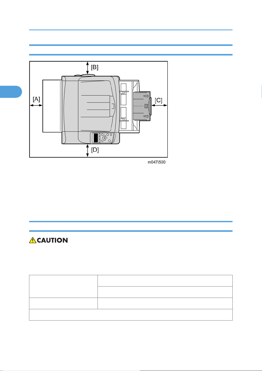
Machine Space Requirement
Place the machine near the power source, providing the clearance as shown below:
A: Over 10 cm (4 inches)
B: Over 10 cm (4 inches)
C: Over 10 cm (4 inches)
D: Over 10 cm (4 inches)
Power Supply
• Make sure the plug is firmly inserted in the outlet.
Avoid multi-wiring.
•
• Be sure to ground the machine.
120 volts, 60 Hz: More than 10 A
Input voltage level
220-240 volts, 50 Hz/60Hz: More than 6 A
Permissible voltage Fluctuation: ±10 %
Do not set anything on the power cord
16
Page 19

Machine Installation
2
Machine Installation
Main Unit and Option Unit
Refer to the "Hardware Guide" for M041 model about the machines installation.
Printer Option
Refer to the "Hardware Guide" for M041 model about the machines installation. If more than two optional
applications are supposed to be installed, do "SD Card Appli Move" described below.
• IPDS option requires an optional memory (128 MB or 256 MB). Install an optional memory first
before installing the IPDS option. Otherwise, the machine may stall when large print job data is sent
to the machine.
SD Card Appli Move
Overview
The service program "SD Card Appli Move" (SP5-873) lets you to copy application programs from one
SD card to another SD card.
Slot 1 and Slot 2 are used to store application programs. However, more than two optional applications
are supplied for this machine. In that case, you can move application programs from Slot 2 to Slot 1 with
the following procedure.
Obey these precautions during the SD Card Appli move procedure:
authentication data is moved with the application program from an SD card to the other SD card.
• The
Authentication fails if you try to use the SD card after you move the application program from this card
to another SD card.
• Do not use an SD card if it has been used for some other work, for example, on a computer. Normal
operation is not guaranteed when such SD card is used.
• Store the original SD card in a safe location after the procedure. The original SD card cannot be used
but it must be saved because (1) the original card is the only proof that the user is licensed to use the
application program, and (2) you may need to check the SD card and its data to solve a problem in
the future.
17
Page 20
2. Installation
2
Move Exec
"Move Exec" (SP5873 1) moves application programs from the original SD card to another SD card. The
application programs are moved from Slot 2 to Slot 1.
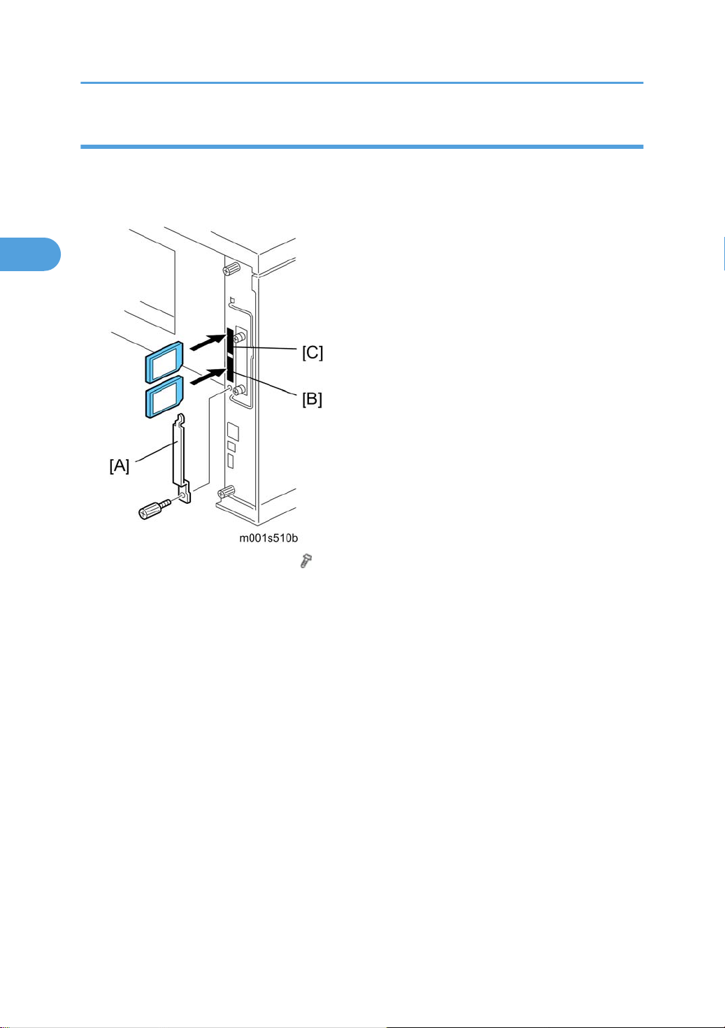
1. Turn off the main power switch.
2. Remove the SD card slot cover [A] ( x 1).
3.
Insert the original SD card with the application in Slot 2 [B] (lower slot).
4. Insert the SD card to receive the application in Slot 1 [C] (upper slot).
5. Turn on the main power switch.
6. Enter the SP mode and do SP5873 1 "Move Exec."
7. Follow the messages on the operation panel to complete the procedure.
8. Exit the SP mode.
9. Turn off the main power switch.
10. Remove the original SD card from Slot 2.
11. Leave the other SD card in Slot 1.
12. Turn on the main power switch.
13. Confirm that the application program runs normally.
14. Tell the customer to store the original SD card in a safe place.
18
Page 21
Machine Installation
2
Undo Exec
"Undo Exec" (SP5873 2) restores an application to its original SD card. The application is moved from
Slot 1 to Slot 2.
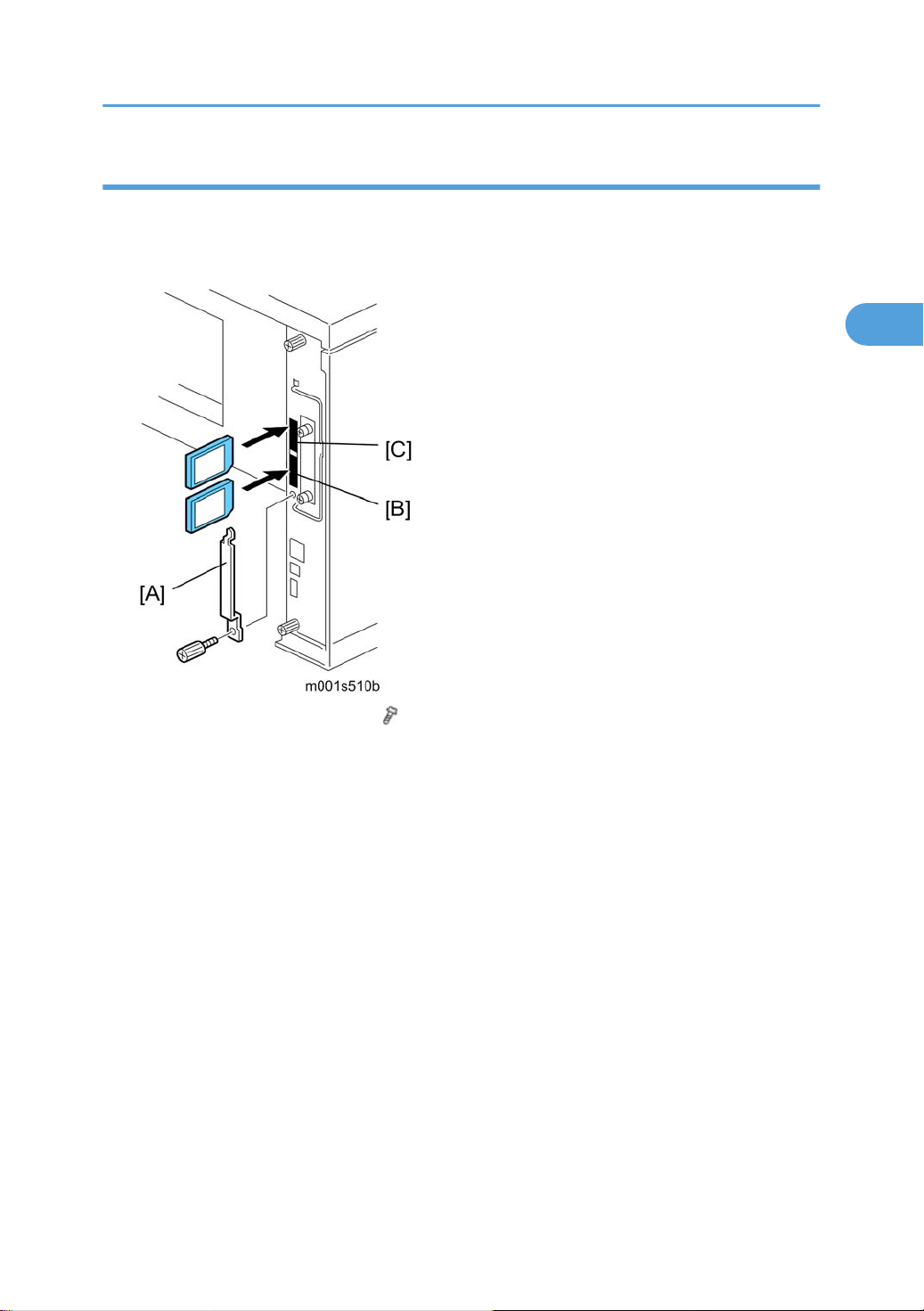
1. Turn off the main power switch.
2. Remove the SD card slot cover [A] ( x 1).
3.
Insert the SD card that currently holds the application in Slot 1 [B].
4. Insert the original SD card to receive the restored application in Slot 2 [C].
5. Turn on the main power switch.
6. Enter the SP mode and do SP5873 "Undo Exec."
7. Follow the messages on the operation panel to complete the procedure.
8. Exit the SP mode.
9. Turn off the main power switch.
10. Remove both SD cards.
11. Insert the SD card with the restored application in Slot 1.
12. Turn on the main power switch.
13. Confirm that the application operates normally.
19
Page 22

2. Installation
2
20
Page 23

3. Preventive Maintenance
3
User Maintenance
The customer can do all PM items with the Maintenance Kit.
Meter-charge mode must be set to "disabled" (engine SP mode 5930).
Cross-reference: "Engine service mode" in the Appendices.
The Operation panel shows "Replace Maintenance Kit" when the PM counter gets to 90K. After the user
replaces the fusing unit in the maintenance kit, the machine automatically resets the PM counter.
Item Quantity Remarks
Fusing unit 1
Transfer roller 1
Paper feed roller 3 For standard and optional tray(s)
Friction pad 3 For standard and optional tray(s)
PSU Fan Filter 1
21
Page 24

3. Preventive Maintenance
3
Service Maintenance
To enable the machine for maintenance by the service technician, the meter-charge mode must be set to
"1: Yes" with SP5930-001.
The table below shows the PM items serviced by the service technician.
After completing a PM procedure, reset the PM counter for the replaced part with SP7-804.
•
7-804-2: Transfer roller
• 7-804-3: Paper feed roller
• 7-804-4: Fusing unit.
Main
Symbol keys: C: Clean/ R: Replace/ L: Lubricate/ I: Inspect
Item 90K EM Quantity Remarks
Paper Feed
Paper Feed Roller R C 1 Clean with water
Friction Pad R C 1 Clean with water
Registration Roller C C 1 Clean with water
Bottom Plate Pad C C 1 Clean with water
Around the Drum
Transfer Roller R 1
Fusing Unit and Paper Exit
Hot Roller R 1
Pressure Roller R 1
Hot Roller Strippers R 5
Fusing Thermistor R C 1
Bushings - Hot Roller R 2
Clean with alcohol if
necessary.
Bushings - Pressure Roller R 2
22
Page 25

Service Maintenance
3
Item 90K EM Quantity Remarks
Fusing Entrance and Exit Guide
Plates
Fusing Unit R 1
Other
PSU Fan Filter R 1
C 1 each
Clean with water or
alcohol
Paper Feed Unit (Option)
Symbol keys: C: Clean/ R: Replace/ L: Lubricate/ I: Inspect
Item 90K EM Quantity Remarks
Paper Feed
Paper Feed Roller R C 1 Clean with water
Friction Pad R C 1 Clean with water
Bottom Plate Pad C C 1 Clean with water
23
Page 26

3. Preventive Maintenance
3
24
Page 27

4. Replacement and Adjustment
4
General
• Turn off the main power switch and unplug the machine before attempting any of the procedures in
this section.
Precautions on Disassembly
Use extreme caution when removing and replacing components. The cables in the machine are located
very close to moving parts; proper routing is a must.
After components have been removed, any cables that have been displaced during the procedure must
be restored as close as possible to their original positions. Before removing any component from the
machine, note any cable routings that may be affected.
Before servicing the machine:
1. Verify that documents are not stored in memory.
2. Remove the toner cartridge before you remove parts.
3. Unplug the power cord.
4. Work on a flat and clean surface.
5. Replace with authorized components only.
6. Do not force plastic material components.
Make sure all components are returned to their original positions.
Laser unit
1. Do not loosen or adjust the screws securing the LD drive board on the LD unit. Doing so will throw the
LD unit out of adjustment.
2. Do not adjust the variable resistors on the LD unit, as these are permanently adjusted at the factory.
If replacement of the LD drive board is necessary, replace the entire LD unit.
3. Keep the polygon mirror and toroidal lens free of dust. Laser performance is very sensitive to dust on
these components.
4. Do not touch the shield glass or the surface of the polygon mirror with bare hands.
5. Do not adjust the Laser Synchronization detector on the LD unit, as these are permanently adjusted
at the factory. If the position of the Laser Synchronization detector has changed from the factory set
position, SC 322 will be shown.
25
Page 28

4. Replacement and Adjustment
4
Transfer Roller
1. Never touch the surface of the transfer roller with bare hands.
2. Be careful not to scratch the transfer roller, as the surface is easily damaged.
Fusing
1. After installing the fusing thermistor, make sure that it is in contact with the hot roller and that the roller
can rotate freely.
2. Be careful to avoid damage to the hot roller stripper pawls and their tension springs.
3. Do not touch the fusing lamp and rollers with bare hands.
4. Make sure that the fusing lamp is positioned correctly and that it does not touch the inner surface of
the hot roller.
Paper Feed
1. Do not touch the surface of paper feed rollers.
2. To avoid misfeeds, the side and end fences in each paper tray must be positioned correctly so as to
align with loaded paper size.
Releasing Plastic Latches
Many of the parts are held in place with plastic latches. The latches break easily, so release them carefully.
To remove such parts, press the hook end of the latch away from the part to which it is latched.
26
Page 29

After Servicing the Machine
4
1. Make sure all parts that require grounding are properly grounded.
2. Make sure the interlock switch is functioning.
3. Do not leave unused solder or parts inside the machine.
4. Do not leave any tools inside the machine.
5. Make sure all wires are properly connected and routed.
6. Make sure wires are not jammed between parts of the machine.
General
27
Page 30

4. Replacement and Adjustment
4
Special Tools
Part Number Description Q’ty Remarks
B6455010 SD Card 1 Used in common with other printers.
B6456705 SD Card Adapter 1 Used in common with other printers.
B6456830 USB Reader/Writer 1 Used in common with other printers.
A0069104
Scanner Positioning Pin
(4 pieces/set)
Used for LD Unit positioning. Used in
1
common with the model K-P series and
other models.
28
Page 31

Exterior Covers
4
Operation Panel
1. Press the button [A], and then open the front door [B].
Exterior Covers
2. Operation panel [A] ( x 1, hooks [B], x 1)
29
Page 32

4. Replacement and Adjustment
4
Rear Cover
1. Rear cover [A]
Upper Cover
1. Remove the AIO.
Rear cover (
2.
Operation panel (
3.
4. Upper cover [A] ( x 3)
p.30)
By-pass Tray
p.29)
1. Open the front door.
30
Page 33

2. Release the both rails [A] (right and left) on the by-pass tray.
4
Close the by-pass tray cover [B].
3.
Exterior Covers
4. Lift the right edge of the by-pass tray cover [A], and then pull the by-pass tray cover to the front.
5. By-pass tray [A].
31
Page 34

4. Replacement and Adjustment
4
Left Cover
• To remove the left cover, separate the machine from the optional paper feed unit first.
Upper cover (
1.
p.30)
2. Left cover [A] ( x 2)
•
[1]: First release the rear left part of the left cover.
• [2]: Pull down the left cover
• [3]: Then remove it.
Front Door
1. Remove the paper tray.
2.
Upper cover (
3.
Left cover (
4.
By-pass tray (
p.30)
p.32)
p.30)
32
Page 35

5. Disconnect two connectors (CN7, CN17) [A] ( x 3).
4
Exterior Covers
6. Release the right hinge [A] of the front door.
7.
Release the left hinge of the front door, and then remove the front door [B].
Right Cover
• To remove the right cover, separate the machine from the optional paper feed unit first.
1. Upper cover ( p.30)
2. Left cover ( p.32)
3. By-pass tray ( p.30)
4. Front door ( p.32)
33
Page 36

4. Replacement and Adjustment
4
5. Lift the right cover [A], and then pull the top edge of the right cover slightly ( x 1, 3 tabs)
Slide the right cover to the front with pulling down the right cover (4 tabs).
6.
• The
fan cover [B] falls after detaching the right cover form the machine. It is because that the fan
cover is held only by the right cover.
Tab Locations on the Right Cover
There are seven tabs on the right cover. Each arrow shows the direction of the tab.
34
Page 37

Laser Unit
4
Laser Unit
• Turn off the main power switch and unplug the machine before attempting any of the procedures in
this section. Laser beams can seriously damage your eyes.
Caution Decal Location
Caution decals are attached as shown below.
• Be sure to turn off the main power switch and disconnect the power plug from the power outlet before
beginning any disassembly or adjustment of the laser unit. This machine uses a class IIIb laser beam
with a wavelength of 785 nm and an output of 6.2 mW. The laser can cause serious eye injury.
35
Page 38

4. Replacement and Adjustment
4
Polygon Mirror Motor
• Turn off the main switch and unplug the machine before attempting any of the procedures in this
section. Laser beams can seriously damage your eyes.
Upper cover (
1.
p.30)
2. Polygon mirror cover [A] ( x 2, tape [B] x 1, x 2)
3. Polygon mirror motor [A] ( x 4, x 1)
• Do not touch the surface of the mirror with bare hands.
Laser Unit
1. Open the front door.
36
Page 39

2. Operation panel ( p.29)
4
1. Upper cover ( p.30)
2. Left cover ( p.32)
3. Disconnect the two harness ( x 1) at the left side.
Remove the ground cable (
4.
x 1).
Laser Unit
5. Laser unit [A] ( x 3, tape [B] x 1, x 2)
37
Page 40

4. Replacement and Adjustment
4
When reinstalling the laser unit
Use the scanner positioning pins (P/N: A0069104) to reinstall the unit.
Set the positioning pins [A] as shown above. Then secure the laser unit.
Laser Diode Unit
1. Laser Unit ( p.36)
2. Spring [A]
38
Page 41

Laser Unit
4
3. LD unit holders [B] (x 2)
4. Loosen the screw [C].
5. Nut [D]
6. LD Unit [E] ( x 1)
• Do not remove the screws that secure the LD board.
Do not touch any variable resistors on the LD board.
•
When installing the LD Unit:
Tighten the screw [C] until the unpainted portion of the screw [a] is not visible.
After installing the LD unit, check the test pattern for the final adjustment (see the following procedure).
Laser Beam Pitch Adjustment
1. Print out the following test patterns (A4 LEF or A3):
Select the test pattern "10.Stitch" with SP 5902-3.
•
• After selecting a pattern, use SP 5902-1 to print one test pattern.
• After completing the adjustment, reset SP 5902-3 to "NoPattern".
39
Page 42

4. Replacement and Adjustment
4
40
2. Check a test pattern. If the laser beam pitch is not correct, the images are as follows.
Third stripe [A] from the leading edge: Vertical black strips seem to appear.
•
3. Adjust the LD unit holder position: Tighten or loosen the screw [C] (see the previous page) until the
printout appears as follows.
• Third stripe [A] from the leading edge: The thin lines are of uniform thickness (no striping effect
should appear on the printout).
Page 43

Image Transfer
4
Transfer Roller
1. Open the front door.
2. Remove the AIO.
Image Transfer
3. Transfer roller [A]
• Do not touch the transfer roller surface.
Toner End Sensor
1. Open the front door.
Remove the AIO.
2.
41
Page 44

4. Replacement and Adjustment
4
3. Toner end sensor [A] (4 hooks, x 1)
42
Page 45

Fusing
4
• Allow time for the unit to cool before doing the following procedure.
Fusing Unit
Fusing
1. Rear cover [A]
Fusing unit [B] (2 hooks [C])
2.
• Lift both hooks before attempting to remove the fusing unit from the machine.
Hot Roller and Fusing Lamp
1. Fusing unit ( p.43)
43
Page 46

4. Replacement and Adjustment
4
2. Left cover [A] ( x 1)
3. Release the fusing tension springs (left [A] and right [B]).
4. Upper fusing unit assembly [A] ( x 4)
44
Page 47

Fusing
4
• Remove
pressure on the unit.
• When reinstalling the fusing unit assembly, install both springs last. The reason for this is to reset
the springs back to their default position.
5. Upper guide plate [A] (hooks)
6.
Right cover [B] (
both springs before taking apart the fusing unit assembly. The reason for this is to relieve
x 1)
7. Left lamp holder [A] ( x 2)
45
Page 48

4. Replacement and Adjustment
4
8. Right lamp holder [A] ( x 2)
Fusing Lamp [B]
9.
• The colored cable must be at the hot roller gear side.
10. Hot roller assembly [A]
46
Page 49

Fusing
4
11. Remove the gear and bearings (left and right) (ring pin x 2)
Hot roller [A]
12.
• Before installing the new hot roller, peel off 3 cm (1 inch) from both ends of the protective sheet on
the new hot roller. Make sure to remove the rest of the paper before starting the machine.
Pressure Roller
1. Fusing unit ( p.43)
2.
Upper fusing unit assembly (
p.43 "Hot Roller and Fusing Lamp")
47
Page 50

4. Replacement and Adjustment
4
3. Lower guide plate [A] ( x 3)
4. Pressure roller levers [A] (spring x 1 each)
Bushings [B]
5.
6. Pressure roller [A]
When reassembling the fusing unit
48
Page 51

Fusing
4
When attaching the pressure roller lever to the lower fusing unit assembly, attach the spring between the
pressure roller lever and fusing unit first. If you try to attach the spring after attaching the pressure roller
lever to the fusing unit, it is difficult to install the spring.
Thermistor and Thermostat
Thermostat
1. Upper fusing unit assembly ( p.43 "Hot Roller and Fusing Lamp")
2. Thermostat [A] ( x 2)
• Do not touch the thermostat with your hands.
•
Do not re-use a thermostat that is already opened. Safety is not guaranteed if you do this.
Thermistor
1. Upper fusing unit assembly ( p.43 "Hot Roller and Fusing Lamp")
49
Page 52

4. Replacement and Adjustment
4
2. Inner wire cover [A] ( x 1)
Grounding plate [B] (
3.
x 2, 1 wire)
4. Remove two screws [A] of the fusing unit connector.
5. Upper wire cover [A] on the top of the fusing upper unit assembly ( x 2)
50
Page 53

6. Fusing unit connector [A] ( x 1, 2 hooks)
4
Fusing
7. Thermistor [A] ( x 1, 1 harness)
• When removing the thermistor, remove the entire unit first and then separate it into two parts.
Hot Roller Strippers
1. Hot roller ( p.43 "Hot Roller and Fusing Lamp")
51
Page 54

4. Replacement and Adjustment
4
2. Hot roller strippers [A] (1 spring each [B])
52
Page 55

Paper Feed
4
Paper Feed Roller
1. Pull out the paper tray.
Paper Feed
2. Paper feed roller [A]
Friction Pad
1. Pull out the paper tray.
2. Friction pad [A] (2 hooks, 1 spring)
53
Page 56

4. Replacement and Adjustment
4
• Remove the paper tray unit from the machine before removing the friction pad.
When reinstalling the friction pad follow this order
1. Replace the spring.
Insert the right side of the friction pad first followed by the left side.
2.
3. Gently push the friction pad down into the slot and then pull forward very slightly.
Paper End Sensor
1. Pull out the paper tray.
54
2. Set the machine [A] on the table with the rear side facing down.
3.
Bottom plate [B] (
x 4)
Page 57

4. Paper feed guide plate [A] ( x 2)
4
5. Paper end feeler [A]
Paper end sensor [B] (hooks,
6.
Remaining Paper Sensors
Paper Feed
x 1)
1. Pull out the paper tray.
Bottom plate (
2.
Paper feed guide plate (
3.
4. Paper remaining feeler [A]
5.
Sensor bracket [B] (
6.
Remaining paper sensor 1 [C] (hooks,
7.
Remaining paper sensor 2 [D] (hooks,
p.54 "Paper End Sensor")
p.54 "Paper End Sensor")
x 1)
x 1)
x 1)
55
Page 58

4. Replacement and Adjustment
4
By-pass Feed
By-pass Feed Unit
1. Upper cover ( p.30)
2. Left Cover ( p.32)
3. Front door ( p.32)
4. By-pass feed unit [A] ( x 4, x 1)
By-pass Feed Roller
1. By-pass feed unit ( p.56)
56
Page 59

2. By-pass feed upper cover [A].
4
3. Slide the by-pass feed roller holders [A] to the both edges ( x 1 each).
By-pass Feed
4. Slide the by-pass feed roller [A] to the left, and then remove it.
By-pass Friction Pad
1. By-pass feed unit ( p.56)
2.
By-pass feed roller (
p.56)
57
Page 60

4. Replacement and Adjustment
4
3. Bushing [A] at the right edge of the by-pass feed roller shaft (Clip x 1)
58
4. By-pass feed gear [A] (spring x 1, clip x 1)
5.
Bushing [B] at the left edge of the by-pass feed roller shaft
6. Slide the by-pass feed roller shaft [C] to the left, and then remove it.
Page 61

7. Bottom bar [A] with two springs
4
By-pass Feed
8. Release the two hooks [A].
9.
Press down the by-pass friction pad [B], and then pull it out (spring x 1).
By-pass Paper Set Sensor
1. By-pass feed unit ( p.56)
59
Page 62

4. Replacement and Adjustment
4
2. By-pass guide plate [A] ( x 3)
60
3. Feeler [A]
4.
Sensor base [B] (
5. By-pass paper set sensor [A] (hook x 3, x 1)
x 1)
Page 63

Paper Exit
4
Paper Exit Sensor
1. Upper cover ( p.30)
Paper Exit
2. Paper exit sensor [A] (hooks, x 1)
Overflow Sensor
1. Upper cover ( p.30)
2. Overflow sensor [A] (hooks, x 1)
Paper Exit Unit
1. Upper cover ( p.30)
61
Page 64

4. Replacement and Adjustment
4
2. Disconnect two connectors and release four clamps.
Take aside the harnesses on the paper exit unit [A].
3.
4. Remove four screws on the paper exit unit.
5.
Remove the gear [A] (hook) and bushing [B].
• This gear is engaged with other drive gears through the timing belt. Check if the timing belt is
6. Paper exit unit [C]
Fusing Exit Sensor
1. Upper cover ( p.30)
2. Paper exit unit ( p.61)
62
correctly installed after installing the paper exit unit.
Page 65

3. Sensor box [A] (hooks)
4
Paper Exit
4. Fusing exit sensor [A] (hooks, x 1)
63
Page 66

4. Replacement and Adjustment
4
Electrical Components
Printer Controller Board
Engine Board
64
1. Printer controller board [A] ( x 2)
2.
NVRAM [B]
• Remove the NVRAM from the old printer controller board and insert it on the new board.
• Remove the Duplex Unit before you remove the controller board.
• The
screws on the printer controller board are hand screws. Gently turn these screws when removing
the printer control board.
• Pull on the handle to remove the printer controller board from the machine.
1. Left cover ( p.32)
2.
Printer controller board (
p.64)
Page 67

3. Bracket [A] ( x 2, 1 grounding wire)
4
Electrical Components
4.
Engine board [B] (
• Remove the NVRAM [C] from the old engine board and insert it on the new board.
x 5, all connectors)
Main Motor
1. Left cover ( p.32)
65
Page 68

4. Replacement and Adjustment
4
2. Main motor [A] ( x 4, x 1)
Relay Clutch
1. Left cover ( p.32)
2. Relay clutch [A] ( x 1, x 1)
Paper Feed Clutch
1. Left cover ( p.32)
2. Release the harness [A] ( x 5, all connectors)
66
Page 69

3. Harness guide [A] (Rivet screw x 1)
4
Electrical Components
4. Clutch cover [A] ( x 1)
67
Page 70

4. Replacement and Adjustment
4
5. Clutch holder [A] ( x 1)
6. Paper feed clutch [A]
Registration Clutch
1. Left cover ( p.32)
Main motor (
2.
Harness guide (
3.
4. Registration clutch [A] ( x 1, x 1)
p.65)
p.66 "Paper Feed Clutch")
Registration Sensor
1. Left cover ( p.32)
2.
Harness guide (
p.66)
68
Page 71

Electrical Components
4
3. Sensor holder [A] ( x 1)
4. Registration sensor [A] (hooks, x 1)
Power Supply Board and High Voltage Supply Board
1. Left cover ( p.32)
2.
Fusing unit (
p.43)
69
Page 72

4. Replacement and Adjustment
4
3. PSU cover [A] ( x 2)
70
4. Remove the two screws [A] at the left of the machine.
5.
Disconnect three cables (pointed by arrow mark).
• Disconnect the cable [B] from the rear of the machine.
6. Main switch link [C] (
7.
Ground cable [D] (
x 1)
x 1: washer screw)
Page 73

8. PSU assembly [A] ( x 3, x 3, all connectors)
4
Electrical Components
9. High voltage supply board [A] ( x 4)
10.
Choke coil [B] (
•
The choke coil [B] is only for EU model.
11. Power supply board [C] (
x 2, x 2, x 1)
x 5)
Fusing Pressure Sensor
1. Right cover ( p.33)
71
Page 74

4. Replacement and Adjustment
4
2. Terminal cover [A] ( x 1)
Fusing pressure sensor [B] (hooks,
3.
Fusing Fan
x 1)
1. Right cover ( p.33)
2. Fusing fan [A] ( x 2, x 2, x1)
• The fusing fan must be reinstalled with the decal facing right. Do not reinstall the fusing fan opposite
to the original position.
PSU Fan
1. Right cover ( p.33)
72
Page 75

Electrical Components
4
2. Terminal cover [A] ( x 1)
PSU fan [B] (
3.
• The
PSU fan must be reinstalled with the decal facing left. Do not reinstall the PSU fan opposite to the
original position.
x 2, x 1)
73
Page 76

4. Replacement and Adjustment
4
Image Adjustment
Registration Adjustment
The registration is adjusted using the user mode; "Maintenance-Registration". For details, see the Printer
Reference operation manual.
Parallelogram Image Adjustment
• Use the scanner positioning pin (P/N: A0069104) for the adjustment.
the following procedure if a parallelogram is printed while adjusting the printing registration using
• Do
a trimming pattern.
74
Page 77

1. Remove the upper cover ( p.30)
4
Image Adjustment
2.
Put a positioning pin in one of the holes.
3. Loosen four screws and move the laser unit.
4. Tighten the laser unit.
5. Print the trimming area pattern to check the image. If it is still the same, repeat steps 3 to 5.
75
Page 78

4. Replacement and Adjustment
4
76
Page 79

5. System Maintenance Reference
5
Service Program Mode
SP Tables
See "Appendices" for the following information:
•
Printer Controller Service Mode Tables
• Engine Mode Tables
• Before accessing the service menu, do the following:
• Confirm that there is no print data in the printer buffer (the Data In LED must not be lit or blinking).
• If there is some data in the buffer, wait until all data has been printed.
Inputting a Value or Setting for a Service Program
Enter the required program mode as explained above. The setting appearing on the display is the current
setting.
the required setting using the "Up/Down arrow" keys [A], then press the "OK" key [B]. The previous
Select
value remains if the "OK" key [B] is not pressed.
77
Page 80

5. System Maintenance Reference
5
Exiting Service Mode
Select "3. End" from the service mode main menu, then press the "OK" key.
78
Page 81

Updating the Firmware
5
Updating the Firmware
• Never turn off the machine while downloading the firmware.
Type of Firmware
The table lists the firmware programs used by the machine. All programs can fit on one SD card.
Program What It Updates
Engine Printer engine control
Network DocBox Document server firmware
Printer Printer feature applications
System Printer management
Network Support Network application
Update Mode Err. Displays if an error occurs.
Verify Data Verifies that the update executed successfully.
Precautions
Handling SD Cards
Observe these precautions when handling SD cards:
• Always
can be corrupted if you insert or remove an SD card while the main power switch is on.
• Never turn off the main power switch during downloading.
• Keep SD cards in a safe location. Never store SD cards in locations where they will be exposed to:
turn off the main power switch before you insert or remove an SD card. Data on an SD card
• High temperature, high humidity
• Direct sunlight
• Strong vibrations
• Magnetic fields generated by machines or electronic devices
• Handle SD cards carefully to avoid dropping them, bending, scratching, etc.
79
Page 82

5. System Maintenance Reference
5
Upload/Download
In this service manual, "upload" and "download" have these meanings:
• Upload: Copying data from the printer to the SD card
• Download: Copying data from the SD card to the printer
Network Connection
A print job sent to the machine during firmware update will interrupt the procedure. Before you start the
firmware update procedure tell the operator:
• The machine must be disconnected from the network.
• The machine cannot be used during firmware update.
Machine Firmware Update
Each program must be updated one a time. Follow the procedure below to update one program.
1. Prepare a card that contains the required program.
2. If the machine is on, switch it off.
3. Remove the SD card cover ( x 1).
4.
Insert the SD card into Slot 2.
5. Turn on the power.
6. "Please Wait" appears, then you will see "Preparing to Start Firmware Update...".
80
Page 83

Updating the Firmware
5
7. Firmware names are displayed on the LCD.
8. Scroll to the program to upgrade, then press [OK].
9. Press the [UPDATE] to start the upgrade.
Loading
*****************
Update done
xxxxxxxxx
10. "Update done" appears on the LCD after completing the firmware updating.
Turn off the power, remove the SD card from Slot 2, and turn on the power.
11.
-or-
If you intend to update another program, leave the SD card in Slot 2 and turn off and on the power.
• The firmware has not updated successfully if the "Update done" message does not appear. If
this occurs, turn the machine power off/on and repeat the procedure.
Error Recovery
Controller
If an error occurs during updating the controller firmware, use the following procedure. This procedure will
force the controller to boot from the firmware SD card.
Prepare an SD card with the required controller firmware version.
1.
2. Turn off the machine and remove the controller.
81
Page 84

5. System Maintenance Reference
5
3. Change the DIP Switch 1 [A] - No.1 setting to "OFF".
4.
Put back the controller
5. Insert the SD card into the SD slot 2 (lower) on the controller.
6. Turn on the machine. The machine automatically starts to download the software.
7. When downloading is finished, "Updated" is displayed.
8. Turn off the machine, then remove the card.
9. Reset the DIP Switch 2 - No.1 setting to "ON" and then put back the controller.
• You must perform steps 5 to 8 for all three firmware cards.
The default settings of the DIP Switches are as followed; "No.1: ON" and "No. 2 to 4: OFF ".
•
10. Turn on the machine, and print the service summary report.
Engine
If a download attempt failed, try downloading the new firmware again using the normal firmware download
procedure described in "Machine Firmware Update".
82
Page 85

Power-On Self Tests
5
Power-On Self Tests
The
controller tests the following devices at power-on. If an error is detected, an error code is stored in the
controller board.
• CPU, ASIC and clock
• Flash ROM
• Resident and optional SDRAM
• NIB
• IEEE 802.11a/g, Gigabit Ethernet or IEEE1284 (if installed)
• NVRAM
• Optional HDD (if installed)
To check the error codes, use engine SP 7832.
Refer to "Controller Error" for details about the error codes.
83
Page 86

5. System Maintenance Reference
5
Dip Switches
Controller Board
DIP Switch 1 (Bit 1) on the controller board is used for the error recovery after the firmware updating
procedure failed.
• The default settings of the DIP Switches are as followed; "No.1: ON" and "No. 2 to 4: OFF ".
84
Page 87

6. Troubleshooting
6
Service Call Conditions
For "Service Call Conditions" information, see "Appendices".
85
Page 88

6. Troubleshooting
6
Electrical Component Defects
Sensors
Component CN Condition Symptom
Paper Exit CN14-20
Paper Overflow CN4-30
Fusing Exit CN5-25
Registration CN14-35
Remaining paper
sensor 1
CN14-26
Open
Shorted
Open
Shorted The paper overflow message is displayed.
Open
Shorted
Open
Shorted
Open
Shorted
The Paper Jam indicator will light whenever a
print is made.
The Paper Jam indicator lights even if there is no
paper.
The paper overflow message is not displayed
even when a paper overflow condition exists.
The Paper Jam indicator will light whenever a
print is made.
The Paper Jam indicator lights even if there is no
paper.
The Paper Jam indicator will light whenever a
print is made.
The Paper Jam indicator lights even if there is no
paper.
The Paper End indicator lights even if paper is
placed in the 1st paper tray.
The Paper End indicator does not light even if
there is no paper in the 1st paper tray.
86
Remaining paper
sensor 2
Paper End CN14-23
CN14-29
Open
Shorted
Open
Shorted
The machine cannot determine the paper nearend condition properly.
The Paper End indicator lights even if paper is
placed in the 1st paper tray.
The Paper End indicator does not light even if
there is no paper in the 1st paper tray.
Page 89

Component CN Condition Symptom
6
High Toner near-end (toner end) is not detected.
Toner End CN14-33
Low The add toner message is displayed.
Envelop mode is not selected even if the
Open
Fusing Pressure Sensor CN5-19
Shorted
• The CN numbers describe the connector number on the engine board.
pressure lever at the fusing unit is set to the
envelop mode.
Envelop mode is always selected even if the
pressure
paper mode.
lever at the fusing unit is set to the other
Switches
Electrical Component Defects
Component CN Condition Symptom
Open
Front Cover Safety CN8-1/3
Shorted
Open
Rear Cover and Paper
Exit Cover Safety
• The CN numbers describe the connector number on the engine board (except for the main switch).
CN4-1/5,
CN4-3/T2
Shorted
The Front Cover Open message is not displayed
even if the front cover is opened.
The Front Cover Open message is displayed
even if the front cover is closed.
The Cover Open (Rear Cover or Paper Exit
Cover)
message is not displayed even if the rear
cover or paper exit cover is opened.
The Cover Open (Rear Cover or Paper Exit
Cover) message is displayed even if the rear
cover or paper exit cover is closed.
87
Page 90

6. Troubleshooting
6
Blown Fuse Conditions
a correct rating fuse for the fuse replacement. Never use a wrong rating fuse. If do so, the machine
• Use
may be damaged.
Rating
Fuse
120 V 220 - 240 V
Power Supply Board
FU1 15 A/125 V 8A/250V Machine does not start.
FU2 5.0 A/125 V 3.15 A/250 V Machine does not start.
FU3 4 A/125 V 4 A/250 V Machine does not start.
FU4 5 A/125 V 5 A/250 V Machine does not start.
Symptom when turning on the main switch
FU5 6.3V/125V 6.3 A/250V
LEDs
No LEDs are used for this model.
"Please Wait" is displayed, but machine
does not start or SC is issued on the LCD.
88
Page 91

7. Energy Saving
7
Energy Save
Energy Saver Modes
The customer should use the energy saver mode correctly to save energy and protect the environment.
The area shaded grey in this diagram represents the amount of energy that is saved.
Energy Saver Mode Setting
"Energy Saver" mode settings can be adjustable with User Mode (Menu > System > Energy Saver).
Energy Saver On/Off
You can specify whether or not to switch Energy Saver.
•
On (Default)
• Off
Energy Saver Timer
Specify time for entering the Energy Saver mode.
• 1 minute (Default)
89
Page 92

7. Energy Saving
7
• 5 minutes
• 15 minutes
• 30 minutes
• 45 minutes
• 60 minutes
Return to Standby Mode
The machine returns to standby mode from energy saver mode after 10 sec.
90
Page 93

Paper Save
7
Paper Save
Effectiveness of Duplex/Combine Function
Duplexing and the combine functions reduce the amount of paper used. This means that less energy overall
is used for paper production, which improves the environment.
1. Duplex:
Reduce paper volume in half!
2. Combine mode:
Reduce paper volume in half!
3. Duplex + Combine:
Using both features together can further reduce paper volume by 3/4!
91
Page 94

7. Energy Saving
7
To check the paper consumption, look at the total counter and the duplex counter.
The total counter counts all pages printed.
For one duplex page, the total counter goes up by 2.
•
• For a duplex job of a three-page original, the total counter goes up by 3.
The duplex counter counts pages that have images on both sides.
• For one duplex page, the duplex counter goes up by 1.
• For a duplex job of a three-page original, the duplex counter will only increase by 1, even though
two sheets are used.
Recommendation
Please explain these features to the customers so they can reduce their paper usage.
Duplex Mode Tables
The following table shows paper savings and how the counters increase for some simple examples of
single-sided and duplex jobs
Duplex mode:
Originals
1 1 1 0 1 0
2 2 1 1 2 1
3 3 2 1 3 1
4 4 2 2 4 2
5 5 3 2 5 2
Simplex Sheet
used
Duplex Sheets
used
Paper
Saved
Total counter Duplex counter
92
Page 95

Paper Save
7
Originals
10 10 5 5 10 5
20 20 10 10 20 10
If combine mode is used, the total and duplex counters work in the same way as explained previously. The
following
combine jobs.
2 in 1 mode:
Originals
1 1 1 0 1 1
2 2 1 1 1 1
3 3 2 1 2 2
4 4 2 2 2 2
5 5 3 2 3 2
Simplex Sheet
used
table shows paper savings and how the counters increase for some simple examples of duplex/
Simplex Sheet
used
Duplex Sheets
used
Duplex Sheets
used
Paper
Saved
Paper
Saved
Total counter Duplex counter
Total counter Duplex counter
10 10 5 5 5 5
20 20 10 10 10 10
Duplex + 2 in 1 mode:
Originals
1 1 1 0 1 1
2 2 1 1 1 1
3 3 1 2 2 2
4 4 1 3 2 2
5 5 2 3 3 3
6 6 2 4 3 3
7 7 2 5 4 4
Simplex Sheet
used
Duplex Sheets
used
Paper
Saved
Total counter Duplex counter
93
Page 96

7. Energy Saving
7
Originals
8 8 2 6 4 4
9 9 3 6 5 5
10 10 3 7 5 5
11 11 3 8 6 6
12 12 3 9 6 6
Simplex Sheet
used
Duplex Sheets
used
Paper
Saved
Total counter Duplex counter
94
Page 97

Model Kr-P2
Machine Code: M047
Appendices
15 December, 2009
Page 98

Page 99

TABLE OF CONTENTS
1. Appendix: Specifications
General Specifications.......................................................................................................................................3
Mainframe......................................................................................................................................................3
Controller........................................................................................................................................................5
Operation Panel LED Specifications.............................................................................................................7
Supported Paper Sizes..................................................................................................................................7
2. Appendix: Troubleshooting Guide
Service Call Conditions...................................................................................................................................11
Summary.......................................................................................................................................................11
SC Code Descriptions.................................................................................................................................11
3. Appendix: SP Mode Tables
SP Tables...........................................................................................................................................................21
Printer Controller Service Mode.................................................................................................................21
Printer Engine Service Mode......................................................................................................................27
INDEX...........................................................................................................................................................103
1
Page 100

2
 Loading...