

Ricoh kc1fax Service Manual

FAX UNIT
(Machine Code: B404)
SERVICE MANUAL
This manual explains the Fax Unit, as well as the following.
!
Handset (Machine Code: B433)
February 20th, 2001
Subject to change.

Lithium Batteries
!
CAUTION
The danger of explosion exists if battery on the FCU is incorrectly replaced.
Replace only with the same or an equivalent type recommended by the
manufacturer. Discard used batteries in accordance with the
manufacturer’s instructions.

TABLE OF CONTENTS
1 INSTALLATION ........................................................................... 1-1
1.1 INSTALLATION REQUIREMENTS...........................................................1-1
1.1.1 ENVIRONMENT...............................................................................1-1
1.1.2 MACHINE LEVEL.............................................................................1-1
1.1.3 MINIMUM SPACE REQUIREMENTS...............................................1-1
1.1.4 POWER REQUIREMENTS..............................................................1-1
1.2 FAX UNIT.................................................................................................. 1-2
1.2.1 ACCESSORY CHECK......................................................................1-2
1.2.2 INSTALLATION PROCEDURE........................................................1-3
1.3 HANDSET.................................................................................................1-7
1.3.1 ACCESSORY CHECK......................................................................1-7
1.3.2 INSTALLATION PROCEDURE........................................................1-7
2 PREVENTIVE MAINTENANCE.................................................... 2-1
2.1 SPECIAL TOOLS AND LUBRICANTS......................................................2-1
2.2 PM TABLE.................................................................................................2-1
3 REMOVAL AND REPLACEMENT............................................... 3-1
3.1 PRECAUTION...........................................................................................3-1
3.2 FCU...........................................................................................................3-1
3.3 NCU...........................................................................................................3-2
3.4 SPEAKER .................................................................................................3-3
4 TROUBLESHOOTING ................................................................. 4-1
4.1 ERROR CODES........................................................................................4-1
4.2 FAX SC CODES........................................................................................4-9
4.2.1 OVERVIEW......................................................................................4-9
4.2.2 SC1201............................................................................................. 4-9
4.2.3 FAX SC CODE TABLE...................................................................4-10
5 SERVICE TABLES....................................................................... 5-1
5.1 SERVICE LEVEL FUNCTIONS.................................................................5-1
5.1.1 HOW TO ENTER AND EXIT SERVICE MODE................................5-1
5.1.2 FUNCTION NO.................................................................................5-1
(1) 01. BIT SW......................................................................................5-1
(2) 02. PARAMETER LIST....................................................................5-2
(3) 03. ERROR CODE..........................................................................5-2
(4) 04. SERVICE REPORT...................................................................5-2
(5) 05. PROTOCOL DUMP...................................................................5-3
(6) 06. MEMORY..................................................................................5-3
(7) 07. RAM CLEAR..............................................................................5-4
(8) 08. NCU...........................................................................................5-4
(9) 09. ROM VERSION.........................................................................5-5
(10) 10. FILE PRINTOUT......................................................................5-5
(11) 11. JOURNAL (ALL)......................................................................5-5
i

(12) 12. RAM TEST..............................................................................5-6
(13) 13. S.S. NUMBER.........................................................................5-6
(14) 14. SERIAL #.................................................................................5-6
(15) 15. HISTORY.................................................................................5-7
5.2 DATA TRANSFER.....................................................................................5-8
5.2.1 FAX SOFTWARE DOWNLOAD.......................................................5-8
5.2.2 FAX SRAM DOWNLOAD.................................................................5-9
5.2.3 FAX SRAM UPLOAD......................................................................5-10
5.3 BIT SWITCHES.......................................................................................5-11
5.3.1 SYSTEM SWITCHES.....................................................................5-11
5.3.2 SCANNER SWITCHES..................................................................5-22
5.3.3 PLOTTER SWITCHES...................................................................5-27
5.3.4 COMMUNICATION SWITCHES.....................................................5-32
5.3.5 G3 SWITCHES...............................................................................5-37
5.4 NCU PARAMETERS...............................................................................5-45
5.5 DEDICATED TRANSMISSION PARAMETERS......................................5-56
5.5.1 PROGRAMMING PROCEDURE....................................................5-56
5.5.2 PARAMETERS...............................................................................5-57
5.6 SERVICE RAM ADDRESSES.................................................................5-60
6 DETAILED SECTION DESCRIPTIONS ....................................... 6-1
6.1 OPERATION DUMP LIST.........................................................................6-1
6.2 PCBS.........................................................................................................6-2
6.2.1 FCU..................................................................................................6-2
6.2.2 NCU (US) .........................................................................................6-4
6.2.3 NCU (EUROPE/ASIA)......................................................................6-5
SPECIFICATIONS.....................................................................SPEC-1
1. GENERAL SPECIFICATIONS.............................................................SPEC-1
2. FEATURES.........................................................................................SPEC-2
2.1 FEATURES LIST.........................................................................SPEC-2
2.2 CAPABILITIES OF PROGRAMMABLE ITEMS...........................SPEC-5
3. OVERALL MACHINE CONTROL........................................................SPEC-6
3.1 SYSTEM CONTROL...................................................................SPEC-6
3.2 POWER DISTRIBUTION.............................................................SPEC-6
3.3 MEMORY BACK-UP....................................................................SPEC-6
4. VIDEO DATA PATH............................................................................SPEC-7
4.1 TRANSMISSION.........................................................................SPEC-7
Memory Transmission and Parallel Memory Transmission...........SPEC-8
Immediate Transmission...............................................................SPEC-8
4.2 RECEPTION................................................................................SPEC-9
5. MACHINE CONFIGURATION...........................................................SPEC-10
ii

20 February, 2001 INSTALLATION REQUIREMENTS
1. INSTALLATION
NOTE: 1) Never install telephone wiring during a lightning storm.
2) Never install telephone jacks in wet locations unless the jack is
specifically designed for wet locations.
3) Never touch uninsulated telephone wires or terminals unless the
telephone line has been disconnected at the network interface.
4) Use caution when installing or modifying telephone lines.
5) Avoid using a telephone (other than a cordless type) during an electrical
storm. There may be a remote risk of electric shock from lightning.
6) If there is a gas leak, do not use the telephone in the vicinity of the leak
to report it.
!
CAUTION
1. Before installing the fax unit, switch off the main power and operation
switches, and disconnect the power cord.
2. The fax unit contains a lithium battery. The danger of explosion exists if
a battery of this type is incorrectly replaced. Replace only with the same
or an equivalent type recommended by the manufacturer. Discard used
batteries in accordance with the manufacturer’s instructions.
Installation
1.1 INSTALLATION REQUIREMENTS
1.1.1 ENVIRONMENT
Refer to the base copier’s service manual.
1.1.2 MACHINE LEVEL
Refer to the base copier’s service manual.
1.1.3 MINIMUM SPACE REQUIREMENTS
Refer to the base copier’s service manual.
1.1.4 POWER REQUIREMENTS
Refer to the base copier’s service manual.
1-1

FAX UNIT 20 February, 2001
1.2 FAX UNIT
1.2.1 ACCESSORY CHECK
No. Description Q’ty
1 Fax unit 1
2 Stamp cartridge 1
3 Main switch cover 1
4 SG3 decal 1
5Mylars 2
6 Operation manual – Basic 1
7 Operation manual – Advanced 1
8 Operation panel 1
9 Function key 1
10 Copy key 1
11 FCU-PSU relay cable 1
12 Telephone cable (only for N. A merica) 1
13 Handset bracket (only for N. America) 1
14 Screw 5
1-2
20 February, 2001 FAX UNIT
1.2.2 INSTALLATION PROCEDURE
!
CAUTION
1. If there is a printer option in the machine, print out all data in the printer
buffer.
2. If a printer option is already installed, remove it first, then install the fax
option. After that, re-install the printer option in the machine.
3. Turn off the main switch and disconnect the power cord and the printer
network cable.
[A]
Installation
B039R901.WMF
[C]
[B]
B404I104.WMF
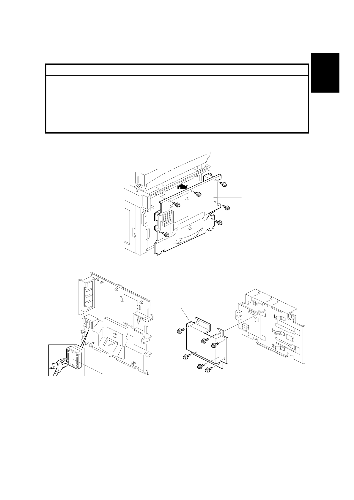
1. Remove the rear cover [A] (6 screws).
2. Cut away the small window [B] on the rear cover as shown.
3. Remove the NCU cover [C] from the fax unit.
NOTE: European and Asian models only
B405I111.WMF
1-3
FAX UNIT 20 February, 2001
4. Connect the following pins on switch TB1 on the FCU and TB1 – TB3 on the
NCU. After that, replace the NCU cover.
NOTE: European and Asian models only
Individual Switch Settings:
FCU NCU
Country
CTR21, Israel 2-5 2-3 OFF ON
Poland 2-5 2-3 ON OFF
Australia 2-5 1-2 OFF ON
New Zealand 2-5 1-2 ON OFF
Malaysia, South Africa 3-4 1-2 OFF ON
Asia and others 3-4 1-2 ON OFF
TB1 TB1 TB2 TB3
NOTE: It is necessary to change the country code in both system switch 0F
and NCU parameter CC.
[H]
[I]
[C]
[H]
[I]
[B]
[A]
[G]
B405I104.WMF
B405I103.WMF
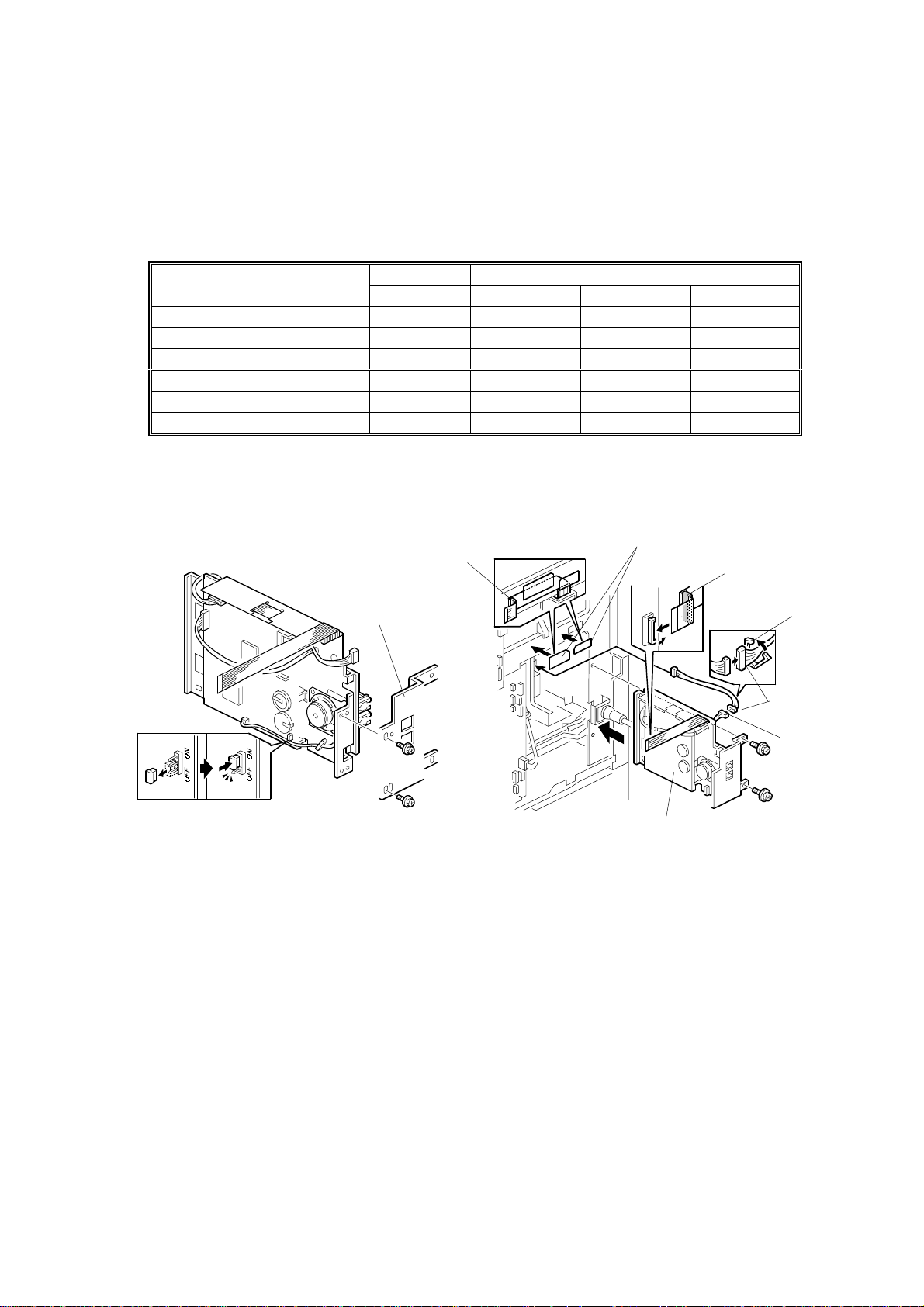
5. Change the battery s witch [A] on the FCU to ON as shown.
6. Attach the bracket [B] (2 screws) as shown.
7. Attach the two mylars [C] to the rear bracket of the mainf rame as shown.
8. Connect the relay cable [D] to the PSU first, then connect it to the FCU-PSU
cable [E], then secure cable [D] with clamp [F], then install the fax unit [G] (2
screws).
[F]
[D]
[E]
9. Run the flat cable [H] through between the mylars and the rear bracket of the
mainframe, then connect the flat cable [H] to the BiCU.
NOTE: If the printer option will be installed at the same time, run the flat cable
[H] through the core [I] (contained in the printer option) as shown.
10. Replace the rear cover.
1-4
20 February, 2001 FAX UNIT
[A]
[D]
B405I105.WMF
[C]
[E]
[B]
Installation
B405I101.WMF
[C]
B405I102.WMF
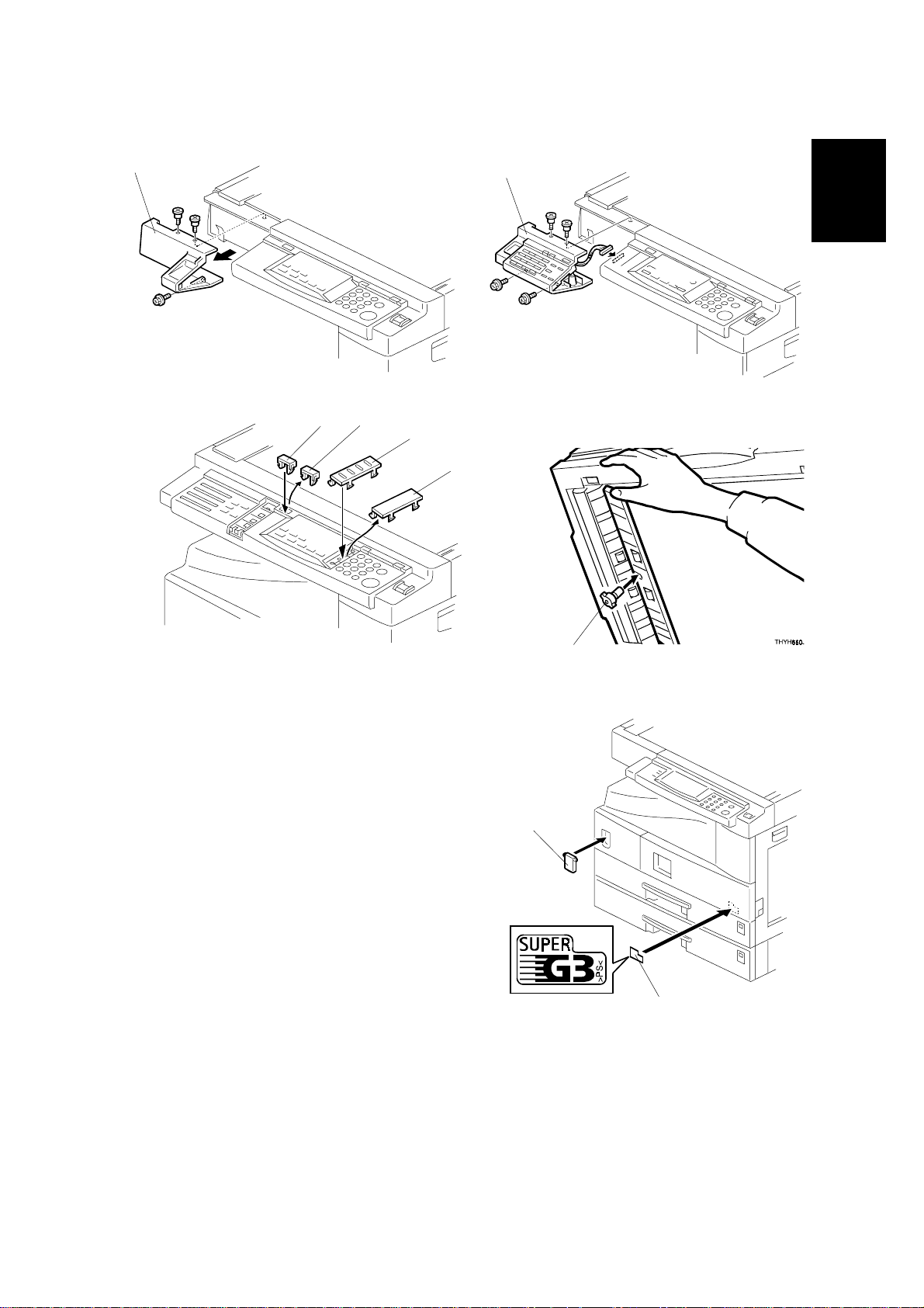
11. Remove the operation panel cover [A]
(3 screws).
12. Install the fax operation panel [B] (4
screws).
13. Remove the small covers [C], then
attach the copy key [D] and function
keys [E] as shown.
14. If the ADF/ARDF has been installed,
install the stamp cartridge [F] as shown.
15. Attach the super G3 decal [G] and cover
[H] to the front cover as shown.
16. Connect the telephone line to the “LINE”
jack at the rear of the machine.
[H]
[F]
[G]
A895I552.WMF
B404I109.WMF
1-5

FAX UNIT 20 February, 2001
17. Plug in the machine and turn on the main power switch.
NOTE: The copier must be connected to a properly-grounded socket outlet.
18. Press the “Facsimile” key. At this time, the display shows: Call Service FAX
SC1201 Data should be initialized.
NOTE: This is not a functional problem. The machine shows this message only
when the fax unit is f irst installed. If the same message appears at the
next power on, check whether the battery switch on the FCU has been
turned on.
19. Press “OK” to initialize the fax unit.
20. Be sure to set the clock. (Date and time ☛ Operation Manual Advanced
Features / 5. Facsimile User Tools)
21. Program items required for fax communication.
1-6

20 February, 2001 HANDSET
1.3 HANDSET
1.3.1 ACCESSORY CHECK
No. Description Q’ty
1 Handset 1
2Screw M3x12 2
3 Screw M3x8 2
4 Handset manual 1
1.3.2 INSTALLATION PROCEDURE
[C]
[B]
[A]
Installation
[D]
[C]
B404I110.WMFB404I111.WMF
1. Attach the bracket [A] enclosed with the fax unit (2 screws) as shown.
2. Remove the label [B] from the handset cradle [C]. Attach the cradle [B] to the
bracket [A] (2 screws), then replace the label [B].
3. Install the handset [D] on the cradle [C], then connect the cable to the “TEL” jack
at the rear of the machine.
1-7

20 February, 2001 SPECIAL TOOLS AND LUBRICANTS
2. PREVENTIVE MAINTENANCE
2.1 SPECIAL TOOLS AND LUBRICANTS
• Flash Memory Card – 4MB (P/N: A2309352)
• Card Case (P/N: A2309351)
2.2 PM TABLE
No PM necessary for the fax option.
Preventive
Maintenance
2-1
20 February, 2001 PRECAUTION
3. REMOVAL AND REPLACEMENT
3.1 PRECAUTION
!
CAUTION
Before starting disassembly, be sure to print all message files in the SAF
memory. Then, turn off the main power switch and disconnect the power
cord and telephone cable for safety.
Lithium Battery
The danger of explosion exists if a battery of this type is incorrectly
replaced. Replace only with the same or an equivalent t ype recommended
by the manufacturer. Discard used batteries in accordance with the
manufacturer’s instructions.
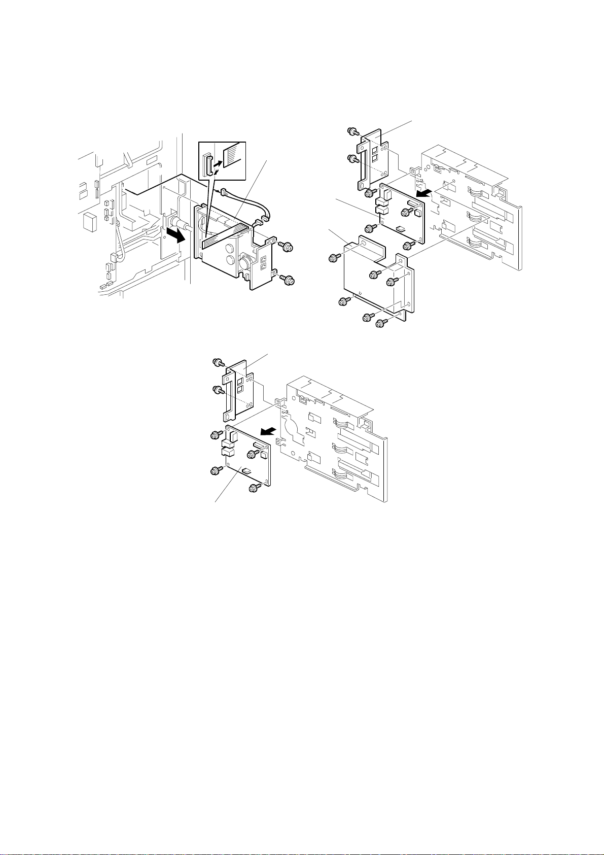
3.2 FCU
Adjustment
Replacement
[A]: Fax unit (! 2, " 2)
[B]: FCU (! 6, " 2)
[A]
B404R500.WMF
[B]
B404R502.WMF
3-1
NCU 20 February, 2001
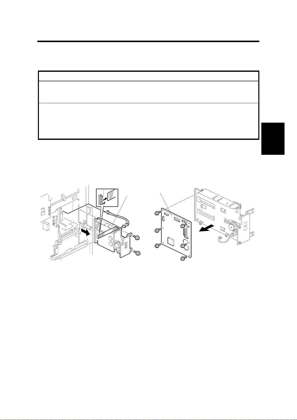
3.3 NCU
[B]
[A]
[D]
[C]
B404R500.WMF
B405I108.WMF
[B]
[D]
B404R503.WMF
[A]: Fax unit (! 2, " 2)
[B]: Bracket (! 2)
[C]: NCU cover (! 6) (European and Asian models only)
[D]: NCU (! 4, " 1)
3-2
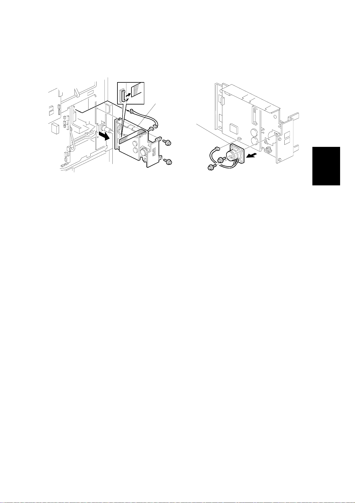
20 February, 2001 SPEAKER
3.4 SPEAKER
[A]
[B]
[A]: Fax unit (! 2, " 2)
[B]: Speaker (! 2, " 1)
B404R500.WMF
B404R501.WMF
Adjustment
Replacement
3-3

20 February, 2001 ERROR CODES
4. TROUBLESHOOTING
4.1 ERROR CODES
If an error code occurs, retry the communication. If the same problem occurs, try to
fix the problem as suggested below. Note that some error codes appear only in the
error code display and on the service report.
Code Meaning Suggested Cause/Action
0-00 DIS/NSF not detected
within 40 s of Start being
pressed
0-01 DCN received
unexpectedly
0-03 Incompatible modem at the
other end
0-04
0-05 Unsuccessful after modem
CFR or FTT not received
after modem training
training at 2400 bps
• Check the line connection.
• Check the NCU - FCU connectors.
• The machine at the other end may be
incompatible.
• Replace the NCU or FCU.
• Check for DIS/NSF with an oscilloscope.
• If the rx signal is weak, there may be a bad
line.
• The other party is out of paper or has a
jammed printer.
• The other party pressed St op during
communication.
• The other terminal is incompatible.
• Check the line connection.
• Check the NCU - FCU connectors.
• Try changing the tx level and/or cable
equalizer settings.
• Replace the FCU or NCU.
• The other terminal may be faulty; try sending to
another machine.
• If the rx signal is weak or defective, there may
be a bad line.
Cross reference
• Tx level - NCU Parameter 01 (PSTN)
• Cable equalizer - G3 Switch 07 (PSTN)
• Dedicated Tx parameters
• Check the line connection.
• Check the NCU - FCU connectors.
• Try adjusting the tx level and/or cable
equalizer.
• Replace the FCU or NCU.
• Check for line problems.
Cross reference
• See error code 0-04.
Trouble-
shooting
4-1

ERROR CODES 20 February, 2001
Code Meaning Suggested Cause/Action
0-06
The other terminal did not
reply to DCS
• Check the line connection.
• Check the FCU - NCU connectors.
• Try adjusting the tx level and/or cable equalizer
settings.
• Replace the NCU or FCU.
• The other end may be defective or
incompatible; try sending to another machine.
• Check for line problems.
Cross reference
• See error code 0-04.
0-07 No post-message
response from the other
end after a page was sent
• Check the line connection.
• Check the FCU - NCU connectors.
• Replace the NCU or FCU.
• The other end may have jamm ed or run out of
paper.
• The other end user m ay have disconnected the
call.
• Check for a bad line.
• The other end may be defective; try sending to
another machine.
0-08
The other end sent RTN or
PIN after receiving a page,
because there were too
many errors
• Check the line connection.
• Check the FCU - NCU connectors.
• Replace the NCU or FCU.
• The other end may have jamm ed, or r un out of
paper or memory space.
• Try adjusting the tx level and/or cable equalizer
settings.
• The other end may have a defective
modem/NCU/FCU; try sending to another
machine.
• Check for line problems and noise.
Cross reference
• Tx level - NCU Parameter 01 (PSTN)
• Cable equalizer - G3 Switch 07 (PSTN)
• Dedicated Tx parameters
0-14
Non-standard post
message response code
received
• Check the FCU - NCU connectors.
• Incompatible or defective remote terminal; try
sending to another machine.
• Noisy line: resend.
• Try adjusting the tx level and/or cable equalizer
settings.
• Replace the NCU or FCU.
Cross reference
• See error code 0-08.
4-2

20 February, 2001 ERROR CODES
Code Meaning Suggested Cause/Action
0-15
The other terminal is not
capable of specific
functions.
The other terminal is not capable of accepting the
following functions, or the other terminal’s
memory is full.
• Confidential rx
• Transfer function
• SEP/SUB/PWD/SID
0-16 CFR or FTT not detected
after modem training in
confidential or transfer
mode
• Check the line connection.
• Check the FCU - NCU connectors.
• Replace the NCU or FCU.
• Try adjusting the tx level and/or cable equalizer
settings.
• The other end may have disconnect ed, or it
may be defective; try calling another machine.
• If the rx signal level is too low, there may be a
line problem.
Cross reference
• See error code 0-08.
0-17 Communication was
interrupted by pressing the
If the Stop key was not pressed and this error
keeps occurring, replace the operation panel.
Stop key.
0-20
Facsimile data not received
within 6 s of retraining
• Check the line connection.
• Check the FCU - NCU connectors.
• Replace the NCU or FCU.
• Check for line problems.
• Try calling another fax machine.
• Try adjusting the reconstruction time for the
first line and/or rx cable equalizer setting.
Cross reference
• Reconstruction time - G3 Switch 0A, bit 6
• Rx cable equalizer - G3 Switch 07 (PSTN)
0-21 EOL signal (end-of-line)
from the other end not
received within 5 s of the
previous EOL signal
• Check the connections between t he FCU,
NCU, & line.
• Check for line noise or other line problems.
• Replace the NCU or FCU.
• The remote machine may be defective or may
have disconnected.
Cross reference
• Maximum interval between EOLs and between
ECM frames - G3 Bit Switch 0A, bit 4
Trouble-
shooting
4-3

ERROR CODES 20 February, 2001
Code Meaning Suggested Cause/Action
0-22
The signal from the other
end was interrupted for
more than the acceptable
modem carrier drop time
(default: 200 ms)
• Check the line connection.
• Check the FCU - NCU connectors.
• Replace the NCU or FCU.
• Defective remote terminal.
• Check for line noise or other line problems.
• Try adjusting the acceptable modem carrier
drop time.
Cross reference
• Acceptable modem carrier drop time - G3
Switch 0A, bits 0 and 1
0-23 Too many errors during
reception
• Check the line connection.
• Check the FCU - NCU connectors.
• Replace the NCU or FCU.
• Defective remote terminal.
• Check for line noise or other line problems.
• Try asking the other end to adjust their tx level.
• Try adjusting the rx cable equalizer setting
and/or rx error criteria.
Cross reference
• Rx cable equalizer - G3 Switch 07 (PSTN)
• Rx error criteria - Communication Switch 02,
bits 0 and 1
0-30 The other terminal did not
reply to NSS(A) in AI short
protocol mode
• Check the line connection.
• Check the FCU - NCU connectors.
• Try adjusting the tx level and/or cable equalizer
settings.
• The other terminal may not be compatible.
Cross reference
• Dedicated tx parameters
0-32 The other terminal sent a
DCS, which contained
functions that the receiving
• Check the protocol dump list.
• Ask the other party to contact the
manufacturer.
machine cannot handle.
0-52 Polarity changed during
communication
0-70
The communication mode
specified in CM/JM was not
available
(V.8 calling and called
terminal)
• Check the line connection.
Retry communication.
• The other terminal did not have a compatible
communication mode (e.g., the other terminal
was a V.34 data modem and not a fax
modem.)
• A polling tx file was not ready at the other
terminal when polling rx was initiated from the
calling terminal.
0-74 The calling terminal fell
back to T.30 mode,
because it could not detect
ANSam after sending CI.
• The calling terminal could not detect ANSam
due to noise, etc.
• ANSam was too short to detect.
• Check the line connection and condition.
• Try making a call to another V.8/V.34 fax.
4-4

20 February, 2001 ERROR CODES
Code Meaning Suggested Cause/Action
0-75
The called terminal fell
back to T.30 mode,
because it could not detect
• The terminal could not detect ANSam.
• Check the line connection and condition.
• Try receiving a call from another V.8/V.34 fax.
a CM in response to
ANSam (ANSam timeout).
0-76 The calling terminal fell
back to T.30 mode,
because it could not detect
a JM in response to a CM
• The called terminal could not detect a CM due
to noise, etc.
• Check the line connection and condition.
• Try making a call to another V.8/V.34 fax.
(CM timeout).
0-77 The called terminal fell
back to T.30 mode,
because it could not detect
a CJ in response to JM
(JM timeout).
• The calling terminal could not detect a JM due
to noise, etc.
• A network that has narrow bandwidth cannot
pass JM to the other end.
• Check the line connection and condition.
• Try receiving a call from another V.8/V.34 fax.
0-79 The called terminal
detected CI while waiting
for a V.21 signal.
0-80
The line was disconnected
due to a timeout in V.34
phase 2 – line probing.
0-81 The line was disconnected
due to a timeout in V.34
phase 3 – equalizer
training.
0-82
The line was disconnected
due to a timeout in the
V.34 phase 4 – control
channel start-up.
0-83
The line was disconnected
due to a timeout in the
V.34 control channel
restart sequence.
Check for line noise or other line problems.
If this error occurs, the called terminal falls back
to T.30 mode.
• The guard timer expired while starting these
phases. Serious noise, narrow bandwidth, or
low signal level can cause these errors.
If these errors happen at the transmitting terminal:
• Try making a call at a later time.
• Try using V.17 or a slower modem using
dedicated tx parameters.
• Try increasing the tx level.
• Try adjusting the tx cable equalizer setting.
If these errors happen at the receiving terminal:
• Try adjusting the rx cable equalizer setting.
• Try increasing the tx level.
• Try using V.17 or a slower modem if the same
error is frequent when receiving from multiple
senders.
0-84
The line was disconnected
due to abnormal signaling
in V.34 phase 4 – control
• The signal did not stop within 10 s.
• Turn off the machine, then turn it back on.
• If the same error is frequent, replace the FCU.
channel start-up.
0-85 The line was disconnected
due to abnormal signaling
in V.34 control channel
• The signal did not stop within 10 s.
• Turn off the machine, then turn it back on.
• If the same error is frequent, replace the FCU.
restart.
0-86 The line was disconnected
because the other terminal
requested a data rate
• The other terminal was incompatible.
• Ask the other party to contact the
manufacturer.
using MPh that was not
available in the currently
selected symbol rate.
Trouble-
shooting
4-5

ERROR CODES 20 February, 2001
Code Meaning Suggested Cause/Action
0-87
The control channel started
after an unsuccessful
primary channel.
• The receiving terminal restarted the control
channel because data reception in the primary
channel was not successful.
• This does not result in an error communication.
0-88
The line was disconnected
because PPR was
• Try using a lower data rate at the start.
• Try adjusting the cable equalizer setting.
transmitted/received 9
(default) times within the
same ECM frame.
2-10 The modem cannot enter
• Replace the FCU.
tx mode
2-11
Only one V.21 connection
• Replace the FCU.
flag was received
2-12 Modem clock irregularity
2-13 Modem initialization error
• Replace the FCU.
• Turn off the machine, then turn it back on.
• Update the modem ROM.
• Replace the FCU.
2-20 Abnormal coding/decoding
• Replace the FCU.
(cpu not ready)
2-50
The machine resets itself
for a fatal FCU system
• If this is frequent, update the ROM, or replace
the FCU.
error
2-51 The machine resets itself
because of a fatal
• If this is frequent, update the ROM, or replace
the FCU.
communication error
3-30 Mismatched specifications
(rx capability)
4-01
Line current was cut
• Check the receive capabilities requested from
the other terminal.
• Check the line connector.
• Check the connection between FCU and NCU.
• Check for line problems.
• Replace the FCU or the NCU.
4-10
Communication failed
because of an ID Code
mismatch (Closed
Network) or Tel. No./CSI
• Get the ID Codes the same and/or the CSI s
programmed correctly, then resend.
• The machine at the other end may be
defective.
mismatch (Protection
against Wrong
Connections)
5-00 Data construction not
• Replace the FCU.
possible
5-01 Data reconstruction not
possible
5-10 DCR timer expired
5-20 Storage impossible
because of a lack of
memory
• Temporary memory shortag e.
• Test the SAF memory.
• Replace the FCU board
5-21 Memory overflow
4-6

20 February, 2001 ERROR CODES
Code Meaning Suggested Cause/Action
5-22
5-23
5-24
Mode table overflow after
the second page of a
scanned document
Print data error when
printing a substitute rx or
confidential rx message
Memory overflow after the
second page of a scanned
document
• Wait for the messages which ar e currently in
the memory to be sent or delete some files
from memory.
• Test the SAF memory.
• Ask the other end to r esend the message.
• Replace the FCU board.
• Try using a lower resolution setting.
• Wait for the messages which ar e currently in
the memory to be sent or delete some files
from memory.
5-25 SAF file access error
6-00
G3 ECM - T1 time out
during reception of
• Replace the FCU board.
• Try adjusting the rx cable equalizer.
• Replace the FCU or NCU.
facsimile data
6-01
G3 ECM - no V.21 signal
was received
6-02 G3 ECM - EOR was
received
6-04 G3 ECM - RTC not
detected
• Check the line connection.
• Check connections from the NCU to the FCU.
• Check for a bad line or defective remote
terminal.
• Replace the FCU or NCU.
6-05
G3 ECM - facsimile data
frame not received within
18 s of CFR, but there was
no line fail
• Check the line connection.
• Check connections from the NCU to the FCU.
• Check for a bad line or defective remote
terminal.
• Replace the FCU or NCU.
• Try adjusting the rx cable equalizer
Cross reference
• Rx cable equalizer - G3 Switch 07 (PSTN)
6-06
6-08
6-09 G3 ECM - ERR received
G3 ECM - coding/decoding
error
G3 ECM - PIP/PIN
received in reply to
PPS.NULL
• Defective FCU.
• The other terminal may be defective.
• The other end pressed Stop during
communication.
• The other terminal may be defective.
• Check for a noisy line.
• Adjust the tx levels of the communicating
machines.
• See code 6-05.
6-10
G3 ECM - error frames still
received at the other end
after all communication
attempts at 2400 bps
• Check for line noise.
• Adjust the tx level (use NCU parameter 01 or
the dedicated tx parameter for that address).
• Check the line connection.
• Defective remote terminal.
Trouble-
shooting
4-7

ERROR CODES 20 February, 2001
Code Meaning Suggested Cause/Action
6-21
V.21 flag detected during
high speed modem
• The other terminal may be defective or
incompatible.
communication
6-22 The machine resets the
sequence because of an
abnormal handshake in the
V.34 control channel
6-99 V.21 signal not stopped
• Check for line noise.
• If the same error occurs frequently, replace the
FCU.
• Defective remote terminal.
• Replace the FCU.
within 6 s
9-61 Memory overflow occurs
Check the SAF.
during reception
22-00
Original length exceeded
the maximum scan length
• Divide the original into a few pages.
• Check the resolution used for scanning. Lower
the scan resolution if possible.
• Add optional page memory.
22-01 Memory overflow while
receiving
• Wait for the files in the queue to be sent .
• Delete unnecessary files from memory.
• Trans fer th e substitute reception files to an
another fax machine, if the machine’s printer is
busy or out of order.
• Expand SAF memory.
22-02
Tx or rx job stalled due to
line disconnection at the
other end
• The job started normally but did not finish
normally; data may or may not have been
received fully.
• Restart the machine.
22-04
23-00
25-00 The machine software
The machine cannot store
received data in the SAF
Data read timeout during
construction
resets itself after a fatal
• Update the ROM
• Replace the FCU.
• Restart the machine.
• Replace the FCU
• Update the ROM
• Replace the FCU.
transmission error occurred
F0-xx V.34 modem error
• Replace the FCU.
4-8

20 February, 2001 FAX SC CODES
4.2 FAX SC CODES
4.2.1 OVERVIEW
If bit 7 of System Switch 1F is at the default setting, when the FCU detects a Fax
SC Code condition other than SC1201, it resets itself automatically. This initializes
the FCU without erasing files in the SAF memory or resetting the switches.
klqbW=
klqbW= For details on Fax SC Code 1201, refer to the following section.
klqbW=klqbW=
If bit 7 of System Switch 1F is changed to “1”, when the FCU detects any Fax SC
Code condition (not only SC1201), it displays the code on the display and stops
working until the fax unit is initialized us ing one of the following methods:
• Hold down the “#” and “*” keys for mo re than 10 s.
• Turn off the main power switch and turn it back on.
The fax unit cannot make automatic service calls in reaction to a Fax SC Code,
because the fax unit cannot make fax communications in fax SC Code conditions.
4.2.2 SC1201
When the FCU detects an unrecoverable error in the SR AM, which requires a
complete SRAM initialization, the fax unit displays this SC Code and stops.
There is no way to recover from this error condition without a complete SRAM
initialization (all the user and service programmed data will be erased ).
The possible causes are:
• SRAM backup battery defect, or TB3 on the FCU is at the “OFF” position
• SRAM on the FCU has a physical defect
• Flash memory card or data copy tool connection was loose
Trouble-
shooting
4-9

FAX SC CODES 20 February, 2001
4.2.3 FAX SC CODE TABLE
SC Code Description
1102 Handshake error with
BiCU at start-up
1111
1112 Base copier’s engine
1120 Interface module error
1201 Unrecoverable FCU 1301 Original size error Check the
1302 Scanner parameter
1303
1304
1305
1306
1308
1313
1314
1316
1318
1323
1324
1326
1328
1334
1338
1401 Command timeout
1402
1403
1404
1405 Command timeout
1406
1410
1601
Command TX/RX error
to/from the BiC U
was reset
SRAM error
error
Software error Initialize the fax
error - after scanning
Software error Initialize the fax
error - during storage
Command timeout
error - original feed out
Software error Initialize the fax
Suggested
Initialize the fax
unit.
(See section
4.2.1.for the
initialization
procedure)
Refer to section
4.2.2.
scanner
mechanism.
Initialize the fax
unit.
unit.
Initialize the fax
unit.
unit.
Check the
connection for
the FCU.
Initialize the fax
unit.
unit.
Action
Sys Switch
1F bit 7 = 0
Automatic
reset
SC Code
display
Automatic
reset
Sys Switch
1F bit 7 = 1
SC Code
display
4-10
20 February, 2001 SERVICE LEVEL FUNCTIONS
5. SERVICE TABLES
5.1 SERVICE LEVEL FUNCTIONS
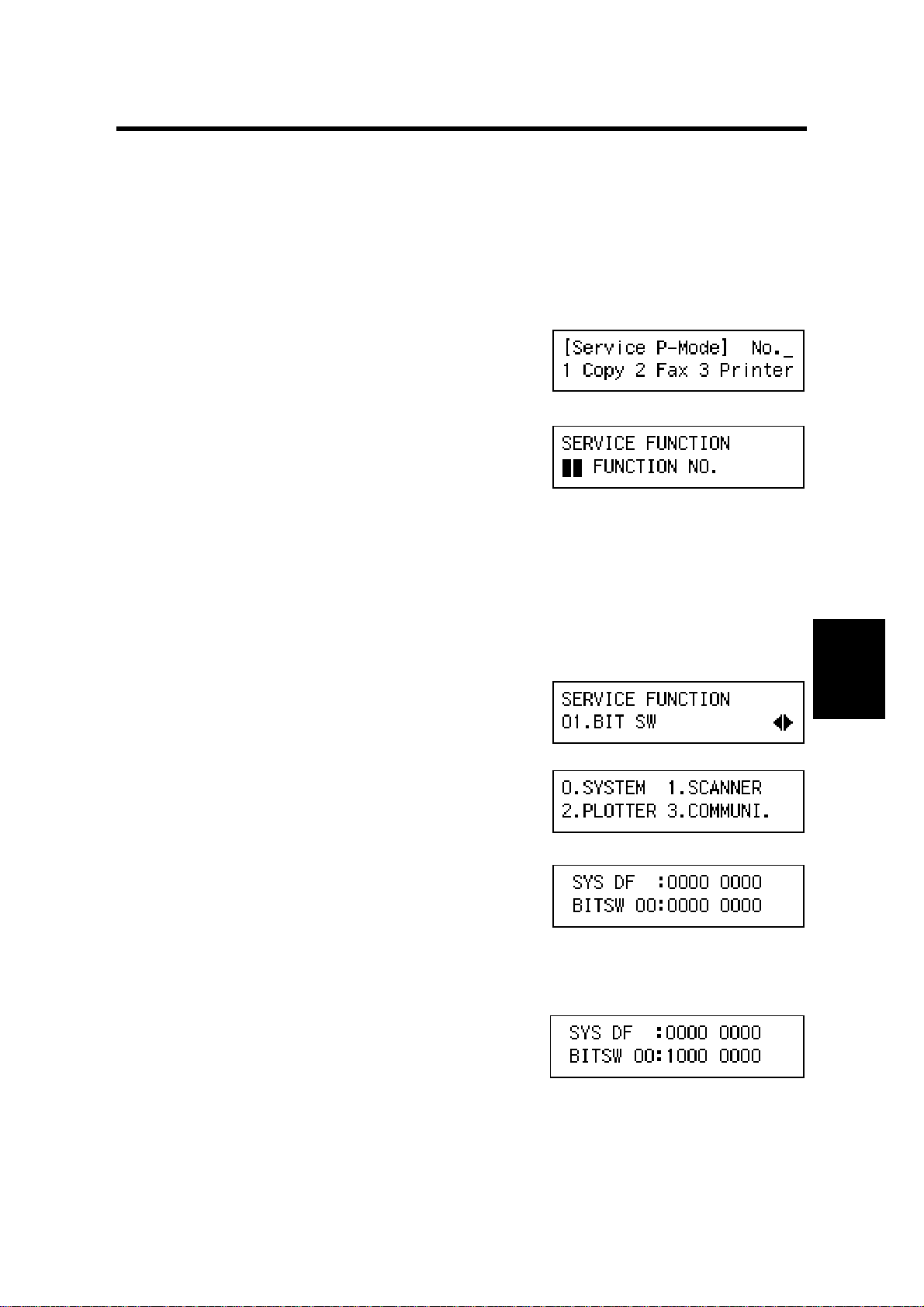
5.1.1 HOW TO ENTER AND EXIT SERVICE MODE
To Enter Fax Service Mode:
1. Ensure that the machine is in standby mode.
2. Press ! " # $, then hold down % for
more than 3 seconds.
The SP mode main menu appears.
3. Press & to enter the fax service mode.
B404M501.BMP
To Exit Fax Service Mode:
Press ‘CANCEL’ key to exit the service mode.
5.1.2 FUNCTION NO.
(1) 01. BIT SW
1. Enter the fax service mode.
2. Press ' (, then ‘OK’.
' — SYSTEM
( — SCANNER
) — PLOTTER
* — COMMUNI
+ — G3
Example
1. Press '
2. Scroll through the bit switches.
To increment the bit switch number:
Press ‘→’
To decrement the bit switch number:
Press ‘←’
B404M502.BMP
B404M503.BMP
B404M504.BMP
B404M505.BMP
Tables
Service
3. Adjust the bit switch.
Example: To change the value of bit 7, press
,.
4. To adjust more bit switches, go to step 2.
To finish, press ‘OK’ then ‘CANCEL’.
5. Exit the service mode.
5-1
B404M506.BMP

SERVICE LEVEL FUNCTIONS 20 February, 2001
(2) 02. PARAMETER LIST
1. Enter the fax service mode.
2. Press ' ).
B404M507.BMP
3. Press ‘OK’.
4. Press -.
B404M508.BMP
(3) 03. ERROR CODE
1. Enter the fax service mode.
2. Press ' *.
3. Press ‘OK’.
4. Scroll through the error codes with the arrow
keys
(4) 04. SERVICE REPORT
1. Enter the fax service mode.
2. Press ' +.
3. Press ‘OK’.
4. Press -.
B404M509.BMP
B404M510.BMP
B404M511.BMP
B404M512.BMP
5-2
20 February, 2001 SERVICE LEVEL FUNCTIONS
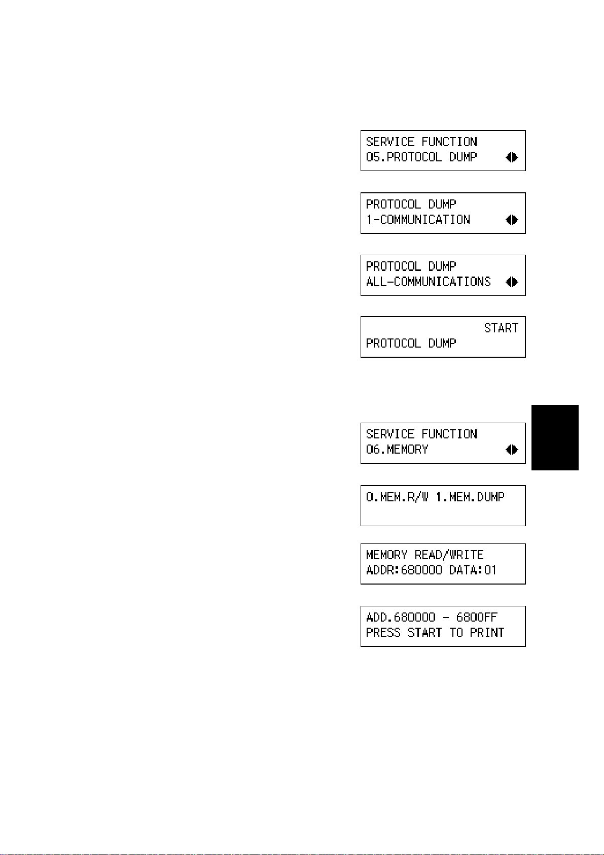
(5) 05. PROTOCOL DUMP
1. Enter the fax service mode.
2. Press ' ..
B404M513.BMP
3. Press ‘OK’.
4. Select ‘1–COMMUNICATION’ or ‘ALL–
COMMUNICATIONS with the arrow keys,
B404M514.BMP
then press ‘OK’.
5. Press -.
B404M515.BMP
(6) 06. MEMORY
1. Enter the fax service mode.
2. Press ' /.
3. Press ‘OK’.
4. Select 0 or 1.
0.–MEM.R/W:
Enter the RAM address and value.
1.–MEM.DUMP:
Enter the start address and end address.
Then press -.
B404M516.BMP
B404M517.BMP
B404M518.BMP
B404M519.BMP
B404M520.BMP
Tables
Service
5-3
SERVICE LEVEL FUNCTIONS 20 February, 2001
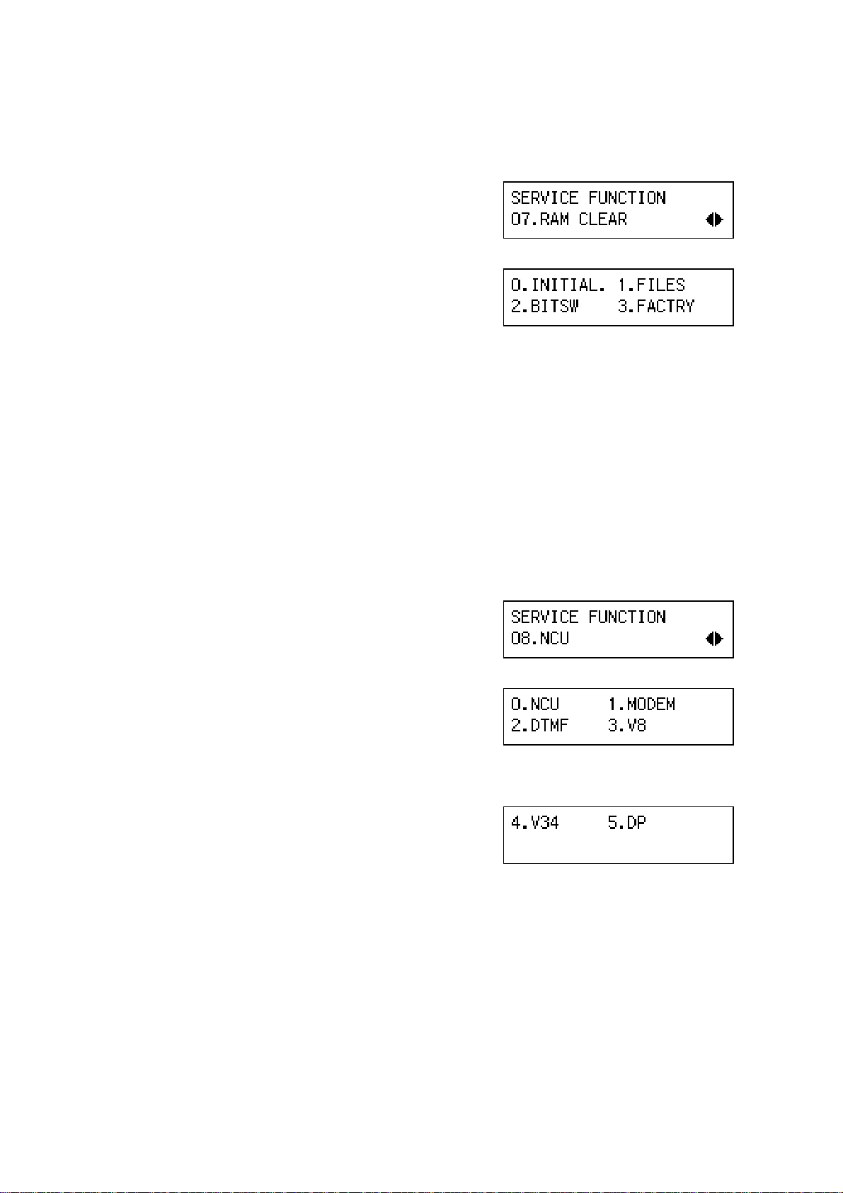
(7) 07. RAM CLEAR
1. Enter the fax service mode.
2. Press ' ,.
B404M521.BMP
3. Press ‘OK’.
4. Select 0, 1, 2, or 3. Then press -.
0.–INITIAL:
B404M522.BMP
Initializes the data in the SRAM, files in the SAF memory and the clock.
1.–FILES:
Erase all files stored in the SAF memory.
2.–BITSW:
Reset the bit switches and user parameters.
3.–FACTRY:
Initialize the data in the SRAM and files in the SAF memory.
(8) 08. NCU
1. Enter the fax service mode.
2. Press ' 0.
3. Press ‘OK’.
4. Select an item from the menu, then press -.
0.–NCU:
NCU parameters
1.–MODEM:
MODEM test
2.–DTMF:
DTMF test
3.–V8:
V8 test
4.–V34:
V34 test
B404M527.BMP
B404M528.BMP
B404M533.BMP
5.–DP:
Dial pulse test
5-4

20 February, 2001 SERVICE LEVEL FUNCTIONS
(9) 09. ROM VERSION
1. Enter the fax service mode.
2. Press ' 1.
B404M536.BMP
3. Press ‘OK’.
The ROM version is displayed.
B404M537.BMP
(10) 10. FILE PRINTOUT
1. Enter the fax service mode.
2. Press ( '.
3. Press ‘OK’.
4. Press ‘Start’. All files in the SAF are printed.
(11) 11. JOURNAL (ALL)
1. Enter the fax service mode.
2. Press ( (.
3. Press ‘OK’, then press -.
B404M538.BMP
B404M539.BMP
B404M540.BMP
B404M541.BMP
Tables
Service
5-5
 Loading...