

Page 1

MODEL K3
RICOH FAX 5510L
SERVICE MANUAL
14 June, 2002
Subject to change
Page 2

!IMPORTANT SAFETY NOTICES
PREVENTION OF PHYSICAL INJURY
1. Before disassembling or assembling parts of the machine and peripherals,
make sure that the machine power cord is unplugged.
2. The wall outlet should be near the machine and easily accessible.
3. If any adjustment or operation check has to be made with exterior covers off
or open while the main switch is turned on, keep hands away from electrified
or mechanically driven components.
4. The inside and the metal parts of the fusing unit become extremely hot while
the printer is operating. Be careful to avoid touching those components with
your bare hands.
HEALTH SAFETY CONDITIONS
Toner is non-toxic, but if you get it in your eyes by accident, it may cause
temporary eye discomfort. Try to remove with eye drops or flush with water as
first aid. If unsuccessful, get medical attention.
OBSERVANCE OF ELECTRICAL SAFETY STANDARDS
1. Do not incinerate toner cartridge. Toner dust may ignite suddenly when
exposed to an open flame.
2. Dispose of used toner cassette in accordance with local regulations. (It is
non-toxic supply.)
3. Dispose of replaced parts in accordance with local regulations.
LITHIUM BATTERIES (MEMORY B ACK-UP)
The danger of explosion exists if a battery of this type is incorrectly replaced.
Replace only with the same or an equivalent type recommended by the
manufacturer. Discard used batteries in accordance with the manufacture’s
instructions.
SAFE AND ECOLOGICAL DISPOSAL
1. Do not incinerate toner bottles or used toner. Toner dust may ignite suddenly
if exposed to an open flame.
2. Dispose of used toner, developer, and organic Photoconductor in
accordance with local regulations. (These are nontoxic supplies.)
3. Dispose of replaced parts in accordance with local regulations.
Page 3
LASER SAFETY
The Center for Devices and Radiological Health (CDRH) prohibits the repair of
laser-based optical units in the field. The optical housing unit can only be repaired
in a factory or at a location with the requisite equipment. The laser subsystem is
replaceable in the field by a qualified Customer Engineer. The laser chassis is not
repairable in the field. Customer engineers are therefore directed to return all
chassis and laser subsystems to the factory or service depot when replacement of
the optical subsystem is required.
!WARNING
Use of controls not specified in this manual, or performance of
adjustments or procedures not specified in this manual, may result in
hazardous radiation exposure.
!WARNING FOR LASER UNIT
WARNING: Turn off the main switch before attempting any of the
procedures in the Laser Unit section. Laser beams can cause
serious damage to eyes.
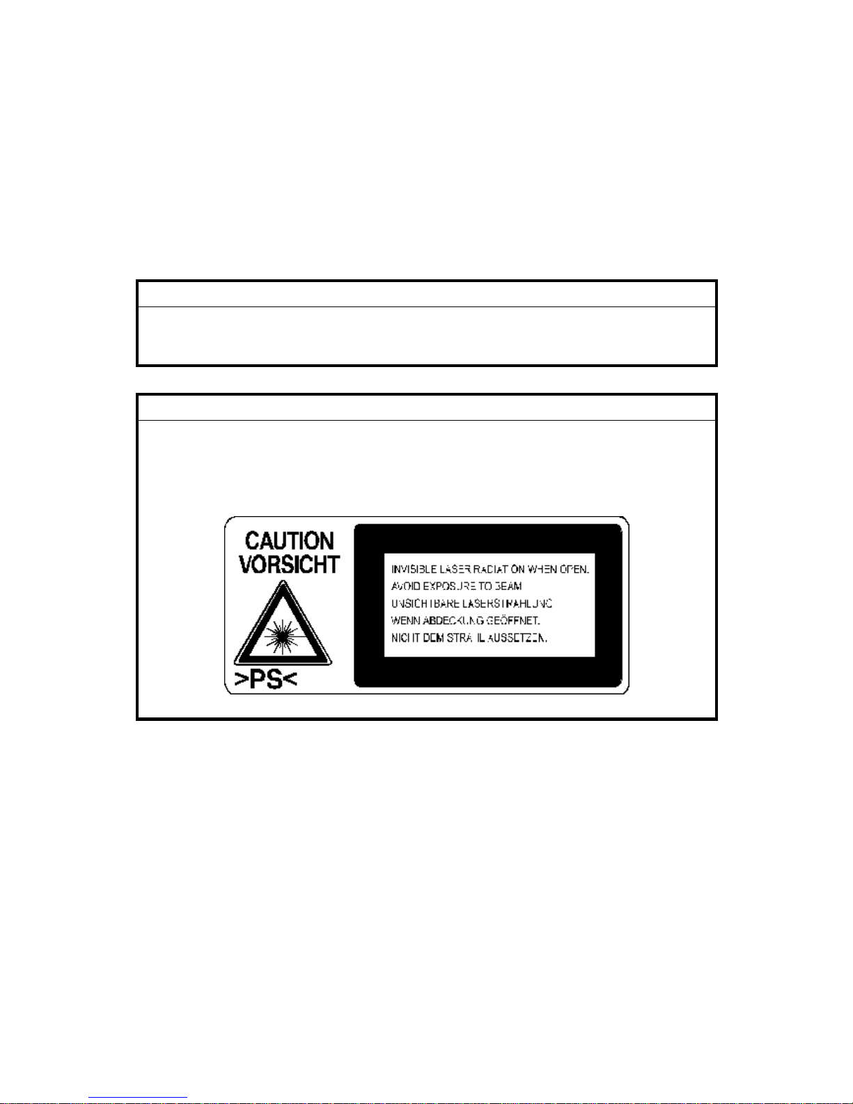
CAUTION MARKING:
H310DECAL.WMF
Page 4

i
TABLE OF CONTENTS
1. INSTALLATION...........................................................................1-1
1.1 MAINFRAME............................................................................................ 1-1
1.2 INSTALLING BASE UNIT/CABINET/SPACER......................................... 1-4
1.3 INSTALLING OPTIONAL UNITS.............................................................. 1-6
1.3.1 PAPER FEED UNIT TYPE 510........................................................ 1-6
1.3.2 BYPASS FEEDER TYPE 510.......................................................... 1-7
1.3.3 ISDN G4 INTERFACE UNIT TYPE 510........................................... 1-9
1.3.4 G3 INTERFACE UNIT TYPE510................................................... 1-12
1.3.5 FAX ON DEMAND TYPE 510........................................................ 1-15
1.3.6 FUNCTION UPGRADE UNIT TYPE 510....................................... 1-17
1.3.7 COUNTER TYPE 510.................................................................... 1-18
1.3.8 FEATURE EXPANDER TYPE 300 40M ........................................ 1-19
2. PREVENTIVE MAIN TENANCE................................................... 2-1
2.1 SPECIAL TOOLS AND LUBRICANTS ............................................... 2-1
2.2 PM TABLE................................................................................................ 2-1
3. REPLACEMENT A ND ADJUSTMEN T........................................ 3-1
3.1 EXTERNAL COVERS............................................................................... 3-1
3.1.1 REMOVING THE ADF FRONT AND REAR COVERS.................... 3-1
3.1.2 REMOVING THE UPPER GUIDE PLATE....................................... 3-1
3.1.3 REMOVING THE REAR COVER..................................................... 3-2
3.1.4 REMOVING THE OPERATION PANEL AND FRONT COVER....... 3-3
3.2 ADF/SCANNER SECTIONS ..................................................................... 3-4
3.2.1 REPLACING THE PICK-UP ROLLER (PART OF THE ADF
MAINTENANCE KIT)....................................................................... 3-4
3.2.2 REPLACING THE FEED ROLLER (PART OF THE ADF
MAINTENANCE KIT)....................................................................... 3-4
3.2.3 REPLACING THE REVERSE ROLLER AND TORQUE LIMITER
(PART OF THE ADF MAINTENANCE KIT)..................................... 3-5
3.2.4 REPLACING THE R0 ROLLER....................................................... 3-6
3.2.5 REPLACING THE R1, R2 AND DOCUMENT EXIT ROLLERS ....... 3-7
3.2.6 REPLACING THE CIS (CONTACT IMAGE SENSOR) (SCANNER)3-9
3.2.7 REMOVING THE STAMP UNIT..................................................... 3-10
3.2.8 ADJUSTING THE SCANNING TOP MARGIN............................... 3-10
3.3 LASER UNIT........................................................................................... 3-11
3.3.1 REPLACING THE LASER SYNCHRONIZATION DETECTOR AND
LD UNITS ...................................................................................... 3-11
3.3.2 REPLACING THE POLYGON MOTOR......................................... 3-12
3.3.3 ADJUSTING THE PRINTING SIDE-TO-SIDE REGISTRATION.... 3-13
Page 5

ii
3.4 AIO CARTRIDGE ................................................................................... 3-14
3.4.1 REPLACING THE AIO CARTRIDGE............................................. 3-14
3.4.2 REPLACING THE TRANSFER ROLLER (PART OF THE FUSING
MAINTENANCE KIT)..................................................................... 3-15
3.4.3 REPLACING THE POWER PACK................................................. 3-16
3.5 PAPER FEED AND REGISTRATION..................................................... 3-17
3.5.1 REPLACING THE PAPER FEED ROLLER ................................... 3-17
3.5.2 REPLACING THE REGISTRATION ROLLER............................... 3-18
3.5.3 ADJUSTING THE PRINTING TOP MARGIN................................. 3-19
3.6 SENSORS.............................................................................................. 3-20
3.6.1 REPLACING THE ADF/MDF SENSORS AND SWITCHES .......... 3-20
3.6.2 REPLACING THE PAPER-END LED BOARD AND PAPER SIZE
SENSOR SWITCH................................................................................... 3-22
3.6.3 REPLACING THE PAPER NEAR END SENSOR......................... 3-23
3.6.4 REPLACING THE UPPER LIMIT AND PAPER END SENSORS.. 3-23
3.6.5 REPLACING THE AIO CARTRIDGE SENSOR............................. 3-24
3.6.6 REPLACING THE PAPER EXIT SENSOR.................................... 3-25
3.6.7 REPLACING THE TONER END SENSOR.................................... 3-26
3.6.8 REPLACING THE REGISTRATION SENSOR .............................. 3-27
3.7 FUSING UNIT......................................................................................... 3-28
3.7.1 REPLACING THE FUSING UNIT (PART OF THE FUSING
MAINTENANCE KIT)..................................................................... 3-28
3.7.2 DISASSEMBLING THE FUSING UNIT.......................................... 3-29
3.7.3 REPLACING THE PRESSURE ROLLER ...................................... 3-30
3.7.4 REPLACING THE HOT ROLLER, FUSING LAMP, AND
THERMOFUSE.............................................................................. 3-31
3.7.5 REPLACING THE THERMISTOR................................................. 3-32
3.7.6 REPLACING THE HOT ROLLER STRIPPERS............................. 3-33
3.8 PCBS...................................................................................................... 3-34
3.8.1 REPLACING THE PSU.................................................................. 3-34
3.8.2 REPLACING THE OPIF/NCU/FCU................................................ 3-35
1. OPIF board...................................................................................... 3-35
2. FCU and MBU boards...................................................................... 3-36
3. NCU board....................................................................................... 3-37
3.8.3 REPLACING THE LCD CONTROLLER AND LCD BOARD.......... 3-38
3.8.4 REPLACING THE POWER PACK................................................. 3-39
3.8.5 REPLACING THE COOLING FAN................................................ 3-40
3.9 BYPASS FEEDER UNIT......................................................................... 3-41
3.9.1 DISASSEMBLING THE BYPASS FEEDER UNITS....................... 3-41
3.9.2 REPLACING THE CLUTCH AND PAPER FEED ROLLER........... 3-42
3.9.3 REPLACING THE PAPER SIZE DETECTION SWITCH............... 3-43
3.9.4 REPLACING THE CONNECTOR AND PAPER END SENSOR.... 3-44
3.10 DATA OR FIRMWARE DOWNLOAD/UPLOAD.................................... 3-45
3.10.1 DATA COPY BETWEEN THE IC CARD AND MACHINE............ 3-46
4. TROUBLESHOOTIN G.................................................................4-1
4.1 COPY QUALITY TROUBLESHOOTING.................................................. 4-1
4.1.1 BLANK COPIES............................................................................... 4-2
4.1.2 BLACK COPIES............................................................................... 4-2
Page 6

iii
4.1.3 DIRTY BACKGROUND ................................................................... 4-3
4.1.4 UNEVEN IMAGE DENSITY............................................................. 4-4
4.1.5 VERTICAL BLACK LINES............................................................... 4-5
4.1.6 HORIZONTAL BLACK LINES.......................................................... 4-6
4.1.7 VERTICAL WHITE LINES................................................................ 4-7
4.1.8 HORIZONTAL WHITE LINES.......................................................... 4-8
4.1.9 BLACK DOTS/SPOTS..................................................................... 4-9
4.1.10 WHITE SPOTS IN BLACK IMAGE AREAS ................................. 4-10
4.1.11 FAINT COPIES............................................................................ 4-11
4.1.12 VERTICAL BLACK BAND............................................................ 4-13
4.1.13 UNFUSED COPIES..................................................................... 4-13
4.1.14 GHOST IMAGE............................................................................ 4-14
4.1.15 TONER ON THE BACK OF THE PRINTER PAPER ................... 4-14
4.1.16 INCORRECTLY ALIGNED OUTPUT (DATA SHIFTED TO THE
RIGHT OR LEFT)........................................................................ 4-15
4.1.17 INCORRECTLY ALIGNED OUTPUT (IMAGE SHIFTED
VERTICALLY)/REDUCED IMAGE .............................................. 4-15
4.2 MECHANICAL PROBLEMS................................................................... 4-16
4.2.1 ADF/SCANNER............................................................................. 4-16
4.2.2 PRINTER....................................................................................... 4-18
4.3 SERVICE CALL CONDITIONS............................................................... 4-21
4.4 ERROR CODES..................................................................................... 4-22
4.5 MODEM STATUS CODES IN V.34 PROTOCOL DUMP........................ 4-32
4.5.1 CALLING SIDE.............................................................................. 4-32
Phase 1 (V.8)..................................................................................... 4-32
Phase 2 (Line Probing)...................................................................... 4-32
Phase 3 (Equalizer Training).............................................................. 4-33
Phase 4 and 5 (Control Channel)....................................................... 4-33
Phase 6 (Primary Channel)................................................................ 4-33
Control Channel (Post Message - Sh)................................................ 4-34
Control Channel (Post Message - PPh)............................................. 4-34
Control Channel Recovery (AC)......................................................... 4-34
V.34 End............................................................................................ 4-35
4.5.2 CALLED SIDE................................................................................ 4-35
Phase 1 (V.8)..................................................................................... 4-35
Phase 2 (Line Probing)...................................................................... 4-35
Phase 3 (Equalizer Training).............................................................. 4-36
Phase 4 and 5 (Control Channel)....................................................... 4-36
Phase 6 (Primary Channel)................................................................ 4-37
Control Channel (Post Message - Sh)................................................ 4-37
Control Channel (Post Message – PPh)............................................ 4-38
Control Channel Recovery (AC)......................................................... 4-38
V.34 End............................................................................................ 4-38
4.6 ERROR CODES FOR THE ISDN OPTION............................................ 4-39
4.6.1 D-CHANNEL LAYER MANAGEMENT........................................... 4-40
4.6.2 D-CHANNEL, LAYER 1................................................................. 4-40
4.6.3 D-CHANNEL LINK LAYER............................................................ 4-40
4.6.4 D-CHANNEL NETWORK LAYER.................................................. 4-41
4.6.5 B-CHANNEL LINK LAYER............................................................. 4-41
Page 7

i
v
4.6.6 B-CHANNEL NETWORK LAYER.................................................. 4-42
4.6.7 TRANSPORT LAYER.................................................................... 4-42
4.6.8 SESSION LAYER.......................................................................... 4-43
4.6.9 DOCUMENT LAYER ..................................................................... 4-44
4.6.10 PRESENTATION LAYER............................................................ 4-44
4.7 ISDN TEST FUNCTION.......................................................................... 4-45
4.7.1 LEDS ............................................................................................. 4-45
4.7.2 BACK-TO-BACK TEST ................................................................... 4-46
5. SERVICE TABLES AND PROCEDURES ...................................5-1
5.1 SERVICE LEVEL FUNCTIONS................................................................ 5-1
5.1.1 BIT SWITCH PROGRAMMING (FUNCTION 01)............................. 5-1
5.1.2 SYSTEM PARAMETER LIST (FUNCTION 02)................................ 5-2
5.1.3 ERROR CODE DISPLAY (FUNCTION 03)...................................... 5-2
5.1.4 SERVICE MONITOR REPORT (FUNCTION 04)............................. 5-2
5.1.5 GROUP 3 PROTOCOL DUMP (FUNCTION 05)............................. 5-2
5.1.6 RAM DISPLAY/REWRITE/MEMORY DUMP (FUNCTION 06)........ 5-3
5.1.7 COUNTER DISPLAY/REWRITE (FUNCTION 07)........................... 5-3
5.1.8 NCU PARAMETERS (FUNCTION 08)............................................. 5-4
5.1.9 MODEM TEST (FUNCTION 08)...................................................... 5-4
5.1.10 DTMF TONE TEST (FUNCTION 08)............................................. 5-5
5.1.11 V.8 MODEM TEST (FUNCTION 08).............................................. 5-5
5.1.12 V.34 MODEM TEST (FUNCTION 08) ............................................ 5-6
5.1.13 OPERATION PANEL TEST (FUNCTION 09)................................ 5-6
5.1.14 LAMP TEST (B/W) (FUNCTION 10).............................................. 5-6
5.1.15 ADF TEST (FUNCTION 10)........................................................... 5-7
5.1.16 LAMP TUNING (FUNCTION 10).................................................... 5-7
5.1.17 LAMP TEST (COLOR) (FUNCTION 10)........................................ 5-8
5.1.18 PRINTER TEST PATTERNS (FUNCTION 11).............................. 5-8
5.1.19 PRINTER FREE RUN (FUNCTION 11)......................................... 5-8
5.1.20 RAM TEST (FUNCTION 12).......................................................... 5-9
5.1.21 DATA COPY (FUNCTION 12)....................................................... 5-9
5.1.22 SERVICE STATION FAX NUMBER (FUNCTION 13)................... 5-9
5.1.23 SERIAL NUMBER (FUNCTION 14)............................................. 5-10
5.1.24 40 MB FLASH MEMORY INITIALIZATION (FUNCTION 16)....... 5-10
5.1.25 40 MB FLASH MEMORY FORMATTING (FUNCTION 16).......... 5-11
5.1.26 40 MB FLASH MEMORY TEST (FUNCTION 16)........................ 5-11
5.1.27 G4 INTERNAL SWITCH PROGRAMMING (FUNCTION 17)....... 5-12
5.1.28 G4 PARAMETER SWITCH PROGRAMMING (FUNCTION 17).. 5-12
5.1.29 PRINTING G4 MEMORY DUMP (FUNCTION 17)....................... 5-13
5.1.30 PRINTING G4 PROTOCOL DUMP LIST (FUNCTION 17).......... 5-13
5.1.31 OPTIONAL G3 BIT SWITCHES (FUNCTION 18)........................ 5-14
5.1.32 OPTIONAL SG3 BOARD RAM DUMP (FUNCTION 18).............. 5-14
5.1.33 OPTIONAL SG3 BOARD NCU PARAME TERS (FUNCTION 18) 5-15
5.1.34 OPTIONAL SG3 BOARD MODEM TEST (FUNCTION 18)......... 5-15
5.1.35 OPTIONAL SG3 BOARD DTMF TONE TEST (FUNCTION 18).. 5-16
5.1.36 OPTIONAL SG3 BOARD V.8 MODEM TEST (FUNCTION 18)... 5-17
5.1.37 OPTIONAL SG3 BOARD V.34 MODEM TEST (FUNCTION 18). 5-17
5.1.38 LAN SW SETTING (FUNCTION 20)............................................ 5-18
Page 8

v
5.1.39 LAN LINK CHECK (FUNCTION 20)............................................. 5-18
5.1.40 LAN LOOP BACK TEST (FUNCTION 20)................................... 5-19
5.1.41 LAN LOG DUMP (FUNCTION 20)............................................... 5-19
5.1.42 LAN PING TEST (FUNCTION 20)............................................... 5-19
5.1.43 JPEG TEST (FUNCTION 21)....................................................... 5-20
5.1.44 IP-FAX IPG3 BIT SWITCHES (FUNCTION 22)........................... 5-20
5.1.45 IP-FAX PORT SETTING (FUNCTION 22)................................... 5-20
5.1.46 ROM VERSION (FUNCTION 23)................................................. 5-21
5.1.47 SENSOR INPUT (FUNCTION 24)............................................... 5-21
5.2 BIT SWITCHES...................................................................................... 5-24
5.2.1 SYSTEM SWITCHES.................................................................... 5-24
5.2.2 SCANNER SWITCHES ................................................................. 5-39
5.2.3 PRINTER SWITCHES................................................................... 5-40
5.2.4 COMMUNICATION SWITCHES.................................................... 5-43
5.2.5 G3 SWITCHES.............................................................................. 5-53
5.2.6 G3-2 SWITCHES........................................................................... 5-61
5.2.7 G4 INTERNAL SWITCHES............................................................ 5-67
5.2.8 G4 PARAMETER SWITCHES....................................................... 5-74
5.3 NCU PARAMETERS .............................................................................. 5-77
5.4 DEDICATED TRANSMISSION PARAMETERS ..................................... 5-85
5.4.1 PROGRAMMING PROCEDURE................................................... 5-85
5.4.2 PARAMETERS.............................................................................. 5-86
5.5 SERVICE RAM ADDRESSES................................................................ 5-90
5.6 SERVICE RAM ADDRESSES: ADF AND SCANNER .......................... 5-110
5.7 SERVICE RAM ADDRESSES: PRINTER ENGINE (PLOTTER).......... 5-112
5.7.1 ADJUSTING THE PRINTING SIDE-TO-SIDE REGISTRATION.. 5-112
5.7.2 ADJUSTING THE PRINTING TOP MARGIN............................... 5-113
6. DETAILED SECTION DESCRIPTIONS.......................................6-1
6.1 ADF/SCANNER........................................................................................ 6-1
6.1.1 OVERVIEW...................................................................................... 6-1
6.1.2 DETAILED DESCRIPTIONS............................................................ 6-2
Document Detection............................................................................. 6-2
Document Pick-up................................................................................ 6-3
Document Feed.................................................................................... 6-4
Stamping.............................................................................................. 6-5
Returning to Ready Status................................................................... 6-6
Image Scanning................................................................................... 6-7
Jam Detection...................................................................................... 6-8
6.2 PRINTER.................................................................................................. 6-9
6.2.1 OVERVIEW...................................................................................... 6-9
6.2.2 LASER EXPOSURE...................................................................... 6-10
Overview............................................................................................ 6-10
Optical Path........................................................................................ 6-10
Auto Power Control (APC)................................................................. 6-11
LD Safety........................................................................................... 6-12
LD Unit Service Call Condition........................................................... 6-12
6.2.3 AIO CARTRIDGE........................................................................... 6-13
Overview............................................................................................ 6-13
Page 9

vi
Drive................................................................................................... 6-14
Drum Charge...................................................................................... 6-15
Development...................................................................................... 6-16
Drum Cleaning................................................................................... 6-18
Service Call Conditions for the Development Section........................ 6-18
6.2.4 TRANSFER AND PAPER SEPARATION...................................... 6-19
Overview............................................................................................ 6-19
Transfer Roller Cleaning.................................................................... 6-20
Service Call Conditions for the Transfer Section................................ 6-20
6.2.5 PAPER FEED................................................................................ 6-21
Overview............................................................................................ 6-21
Paper Size Detection ......................................................................... 6-23
Bottom Plate Lift, Upper Limit Detection and Paper End Detection.... 6-24
Paper Near-end Detection.................................................................. 6-25
Paper Feed........................................................................................ 6-25
By-pass Tray...................................................................................... 6-26
6.2.6 FUSING......................................................................................... 6-28
Overview............................................................................................ 6-28
Fusing................................................................................................ 6-30
Fusing Unit Drive................................................................................ 6-30
Fusing Pressure Roller, Separation, Exit........................................... 6-31
Fusing Drive Release......................................................................... 6-31
Fusing Temperature Control .............................................................. 6-32
Cooling Fan Control........................................................................... 6-33
Fusing Unit Service Call Conditions................................................... 6-34
6.3 OPTIONAL PAPER FEED UNITS.......................................................... 6-35
6.3.1 OVERVIEW.................................................................................... 6-35
6.3.2 MECHANISMS............................................................................... 6-36
Paper Size Detection ......................................................................... 6-36
Bottom Plate Lift, Upper Limit Detection and Paper End Detection.... 6-37
Paper Near-end Detection.................................................................. 6-38
Paper Feed........................................................................................ 6-39
Jam Detection.................................................................................... 6-39
6.4 PCBS...................................................................................................... 6-40
6.4.1 FCU ............................................................................................... 6-40
6.4.2 OPIF (OPTION INTERFACE BOARD) .......................................... 6-45
6.4.3 NCU............................................................................................... 6-46
6.4.4 PSU ............................................................................................... 6-46
6.4.5 NICF (NETWORK INTERFACE CARD FOR FACSIMILE)............ 6-47
6.4.6 SG3-D BOARD.............................................................................. 6-49
6.4.7 SIG4 BOARD................................................................................. 6-50
6.5 SYSTEM FEATURES............................................................................. 6-51
6.5.1 VERTICAL BLACK LINE CORRECTION....................................... 6-51
Overview............................................................................................ 6-51
Count Detection Parameters List ....................................................... 6-52
Settings for Vertical Black Line Detection.......................................... 6-53
Vertical Black Line Warning Message................................................ 6-53
Page 10

vii
6.5.2 BLANK PAGE DETECTION........................................................... 6-54
Blank Page Detection Operation........................................................ 6-54
Blank Page Detection Switch Settings ............................................... 6-54
6.5.3 ENERGY SAVER MODE............................................................... 6-55
Overview............................................................................................ 6-55
Setting the Energy Saver Mode Timer............................................... 6-56
How the Energy Saver Mode Operates.............................................. 6-57
Important Points About Energy Saver and Standby........................... 6-60
6.5.4 ERASE ALL REGISTERED SETTINGS ........................................ 6-61
6.5.5 RECEIVING FROM A FAX INFORMATION SERVICE.................. 6-62
6.5.6 DUAL ACCESS.............................................................................. 6-63
Dual Access Jobs and Resources...................................................... 6-63
Additional Dual Access Limitations.................................................... 6-64
Simultaneous Broadcasting................................................................6-65
6.5.7 OPERATION LOG......................................................................... 6-66
Memory Dump List............................................................................. 6-66
6.5.8 SENDING COLOR DOCUMENTS ................................................. 6-68
6.5.9 SCAN RESOLUTION..................................................................... 6-69
SPECIFICATIONS.................................................................... SPEC-1
1.1 SPECIFICATIONS.......................................................................SPEC-1
1.2 FEATURES..................................................................................SPEC-3
1.2.1 FEATURES LIST......................................................................SPEC-3
1.2.2 CAPABILITIES OF PROGRAMMABLE ITEMS ........................SPEC-6
1.3 COMPONENT LAYOUT..............................................................SPEC-7
1.3.1 MECHANICAL COMPONENTS................................................SPEC-7
1.3.2 ELECTRICAL COMPONENTS.................................................SPEC-8
PCBs.............................................................................................SPEC-9
Motors.........................................................................................SPEC-10
Sensors.......................................................................................SPEC-10
Interlock Switch...........................................................................SPEC-11
Others.........................................................................................SPEC-11
1.3.3 DRIVE LAYOUT......................................................................SPEC-12
Components................................................................................SPEC-12
1.4 POWER DISTRIBUTION...........................................................SPEC-13
1.4.1 DISTRIBUTION DIAGRAM.....................................................SPEC-13
1.4.2 MEMORY BACK-UP CIRCUIT ................................................ SPEC-14
Page 11
14 June, 2002 MAINFRAME
1-1
Installation
1. INSTALLATION
!CAUTION
Do the following before installing an optional unit:
1. Print out all messages stored in the memory.
2. Print out the lists of user-programmed items and the system parameter list.
3. Turn off the main switch, and disconnect the power plug.
1.1 MAINFRAME
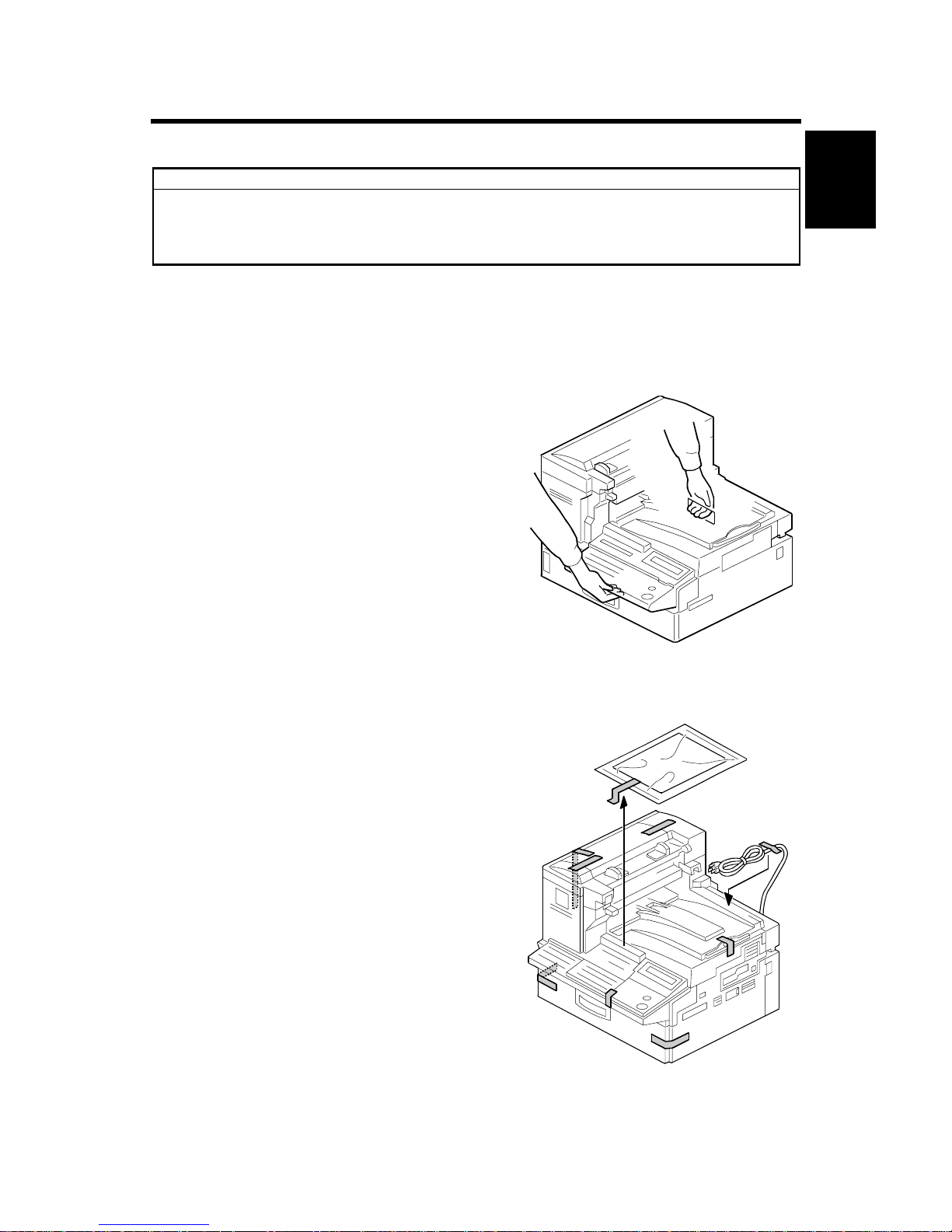
1. Remove the mainframe from the box.
2. Remove the shipping tape.
H310I939.WMF
H310I001.WMF
Page 12
MAINFRAME 14 June, 2002
1-2
3. Remove the shock absorber [A] and sheet
[B].
4. Remove the shock absorbers and
shipping tape from the paper trays.
5. Attach the document exit tray and
document tray.
6. Open the ADF unit and attach the handset
bracket [C].
7. Open the left cover and remove the AIO cartridge.
8. Shake the AIO cartridge left to right then
back and forth about 7-8 times (total).
Then, remove the toner ribbon seal.
9. Reinstall the AIO cartridge.
10. Load the desired paper in the paper trays,
and set up the paper size dials
accordingly
11. Turn the machine ON, then follow the
display to program the following items:
Date/time, PSTN line type (tone/pulse
dial), own name, fax header, fax number.
12. Program the machine serial number in
Service mode, then exit Service mode.
H310I002.WMF
H310I940.WMF
H310I991.WMF
[A]
[B]
[C]
Page 13
14 June, 2002 MAINFRAME
1-3
Installation
13. Remove the backing from the brand
plaque [A] and avoid touching the
adhesive surface. Place the brand
plaque in the depression on the ADF
front cover. Taking care that the brand
plaque is orientated correctly and
aligned straight. Once in place, apply
even pressure beginning at the center
of the brand plaque moving toward the
outer edges. This will insure that it is
well adhered to the surface.
H310I059.WMF
[A]
Page 14
INSTALLING BASE UNIT/CABINET/SPACER 14 June, 2002
1-4
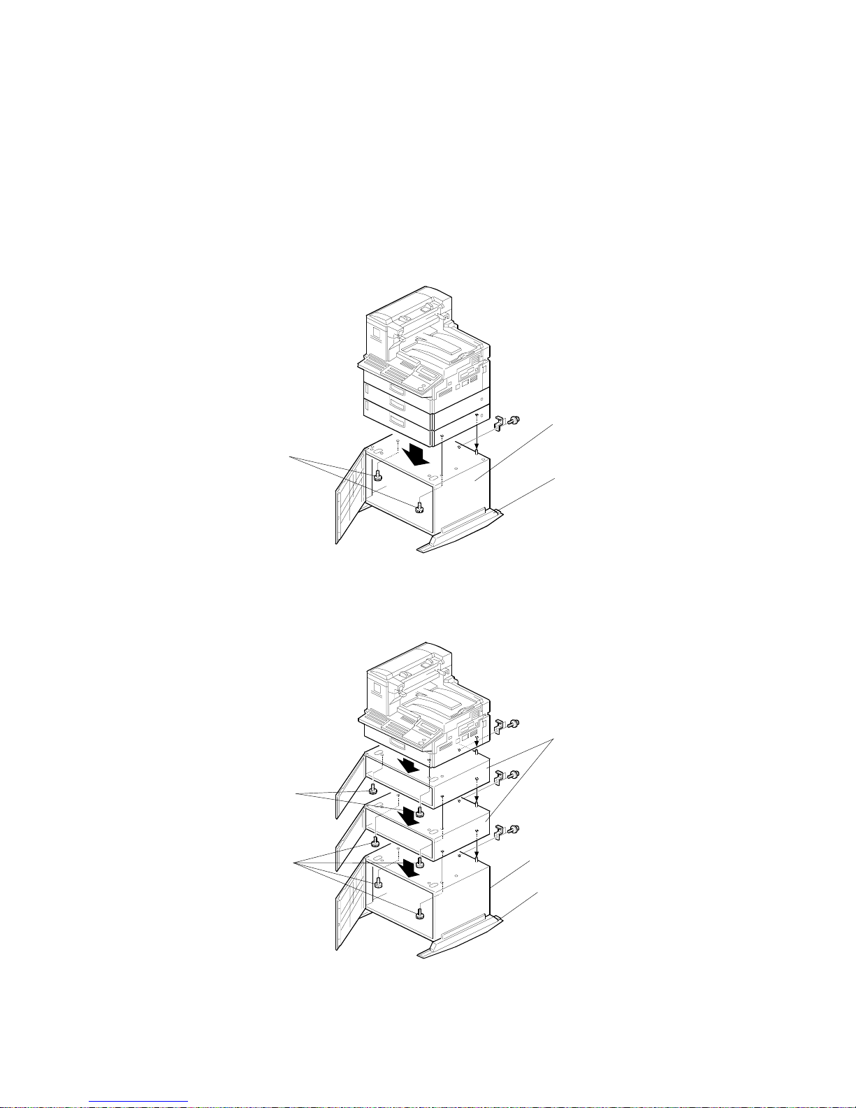
1.2 INSTALLING BASE UNIT/CABINET/SPACER
To ensure proper machine stability, be sure to attach the Cabinet Type 510 when
installing 2 PFUs/Spacer Type 510, or the Base Unit Type 51 0 when installing 3 or
more PFUs/Spacer Type 510 (both of which have Support Boards attached).
Please refer to the following examples:
Example 1: Mainframe, PFU X 2 and Cabinet Type 510
Example 2: Mainframe, Spacer Type 510 X 2 and Cabinet Type 510
H310I056.WMF
H310I057.WMF
Cabinet Type 510
M4 screws
Support Board
Cabinet Type 510
Support Board
M3 screws
M4 screws
Spacer Type 510
Page 15
14 June, 2002 INSTALLING BASE UNIT/CABINET/SPACER
1-5
Installation
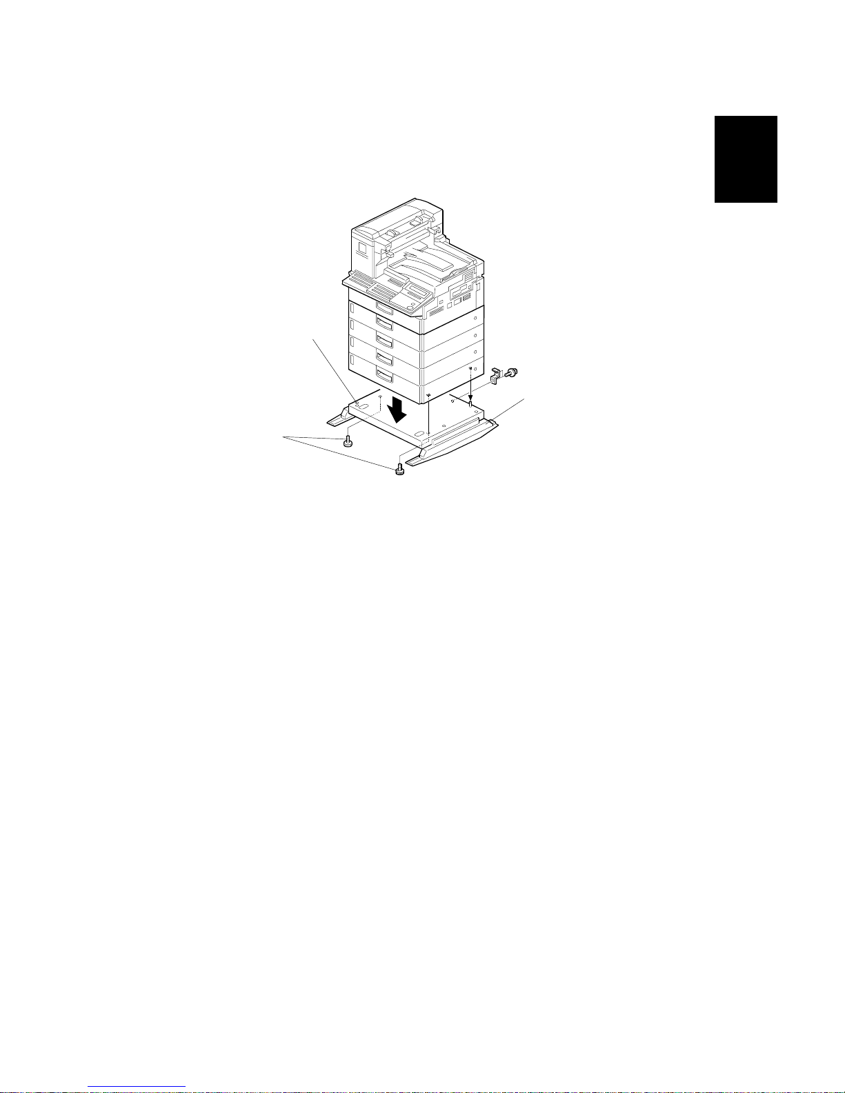
Example 3: Mainframe, PFU X 4 and Base Unit Type 510
NOTE: As shown in the illustrations above, when attaching any of the units directly
under the mainframe, use the two forward parallel screw-holes. For all
other attachments, use the two diagonally positioned screw holes.
H310I058.WMF
Base Unit Type 510
Support Board
M3 screws
Page 16
INSTALLING OPTIONAL UNITS 14 June, 2002
1-6
1.3 INSTALLING OPTIONAL UNITS
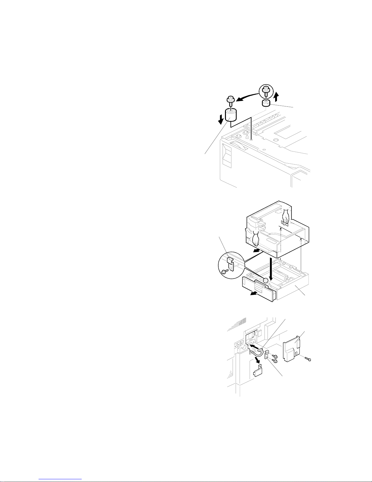
1.3.1 PAPER FEED UNIT TYPE 510
1. When installing optional Paper Fe ed Units 2,
3 or 4 (i.e. ones not attached directly under
the mainframe), it is necessary to replace the
large leg [A] with the small leg [B] enclosed
with the unit.
NOTE: Remove the 2 tie-wraps securing the
paper feed rollers (located under the
red tag).
2. Place the mainframe and any attached PFUs
on top of the Paper Feed Unit [C], then
secure the two with the bracket [D] (1 screw)
on the front of the machine
NOTE: If the existing mainframe and PFU
assembly is too heavy, disassemble
them and install them one by one on
top of the new optional PFU.
3. Remove the connector cover [E] (1 screw)
and secure the new PFU to the mainframe
(or PFU) above it with the bracket [F] (2 screws).
Then, connect the harness [G] to the machine
and reattach the connector cover.
4. Plug in the machine and turn on the main power
switch.
5. Print the System Parameter List from inside
Service mode, then make sure that
“CASSETTE” is listed as an option. Then exit
Service mode.
6. Add some paper and make some test prints
using the newly installed PFU.
H206I601.WMF
H206I602.WMF
H206I603.WMF
[B]
[A]
[C]
[D]
[E]
[F]
[G]
Page 17

14 June, 2002 INSTALLING OPTIONAL UNITS
1-7
Installation
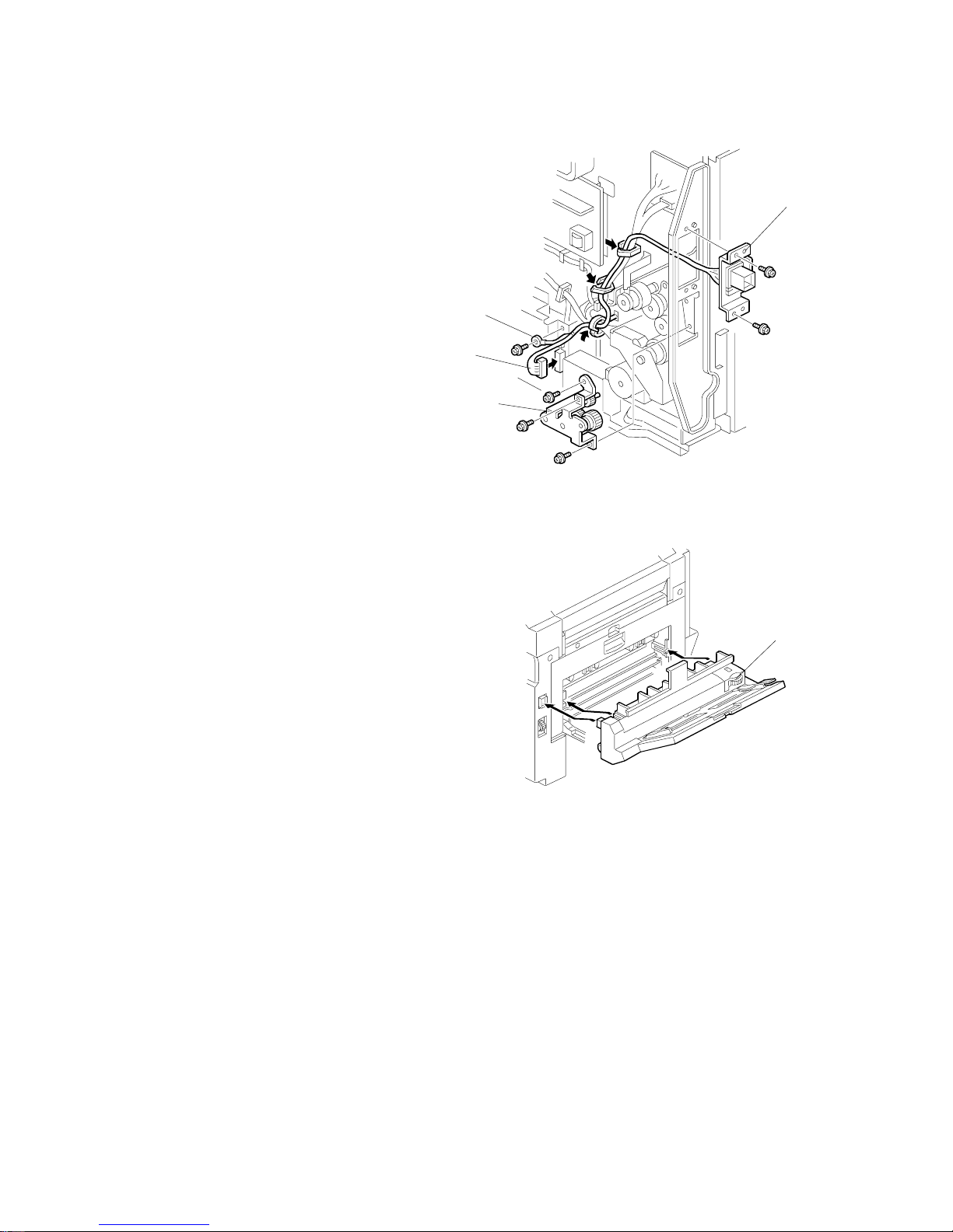
1.3.2 BYPASS FEEDER TYPE 510
1. Remove the rear cover [A] (7 screws) and
small cut-out [B] as shown.
2. Open the large cover. Then, remove the 2
screws [C] as shown to release the small
cover.
3. Attach the 2 magnet catches [D], 2 small
brackets [E] and 2 cushions [F]. Then attach
the knob [G] (2 screws) to the small cover as
shown.
H207I029.WMF
H207I030.WMF
H207I031.WMF
[A]
[B]
[C]
[G]
[F]
[E]
[D]
Page 18
INSTALLING OPTIONAL UNITS 14 June, 2002
1-8
4. Attach the gear assembly [H] to the
back of the machine. Then, attach the
connector [I] and lead the bypass
feeder harness through the 3 clamps
as shown. Finally, connect the end of
the harness [J] and secure the
grounding wire [K] to the mainframe.
5. Reattach the rear cover.
6. Attach the bypass feeder [L] to the
machine.
7. Plug in the machine and turn on the main power switch.
8. Print the System Parameter List from inside Service mode, then make sure that
“BY-PASS” is listed as an option. Then, exit Service mode.
9. Add some paper and make some test prints using the newly installed Bypass
Feeder.
H207I032.WMF
H207I033.WMF
[H]
[I]
[J]
[K]
[L]
Page 19
14 June, 2002 INSTALLING OPTIONAL UNITS
1-9
Installation
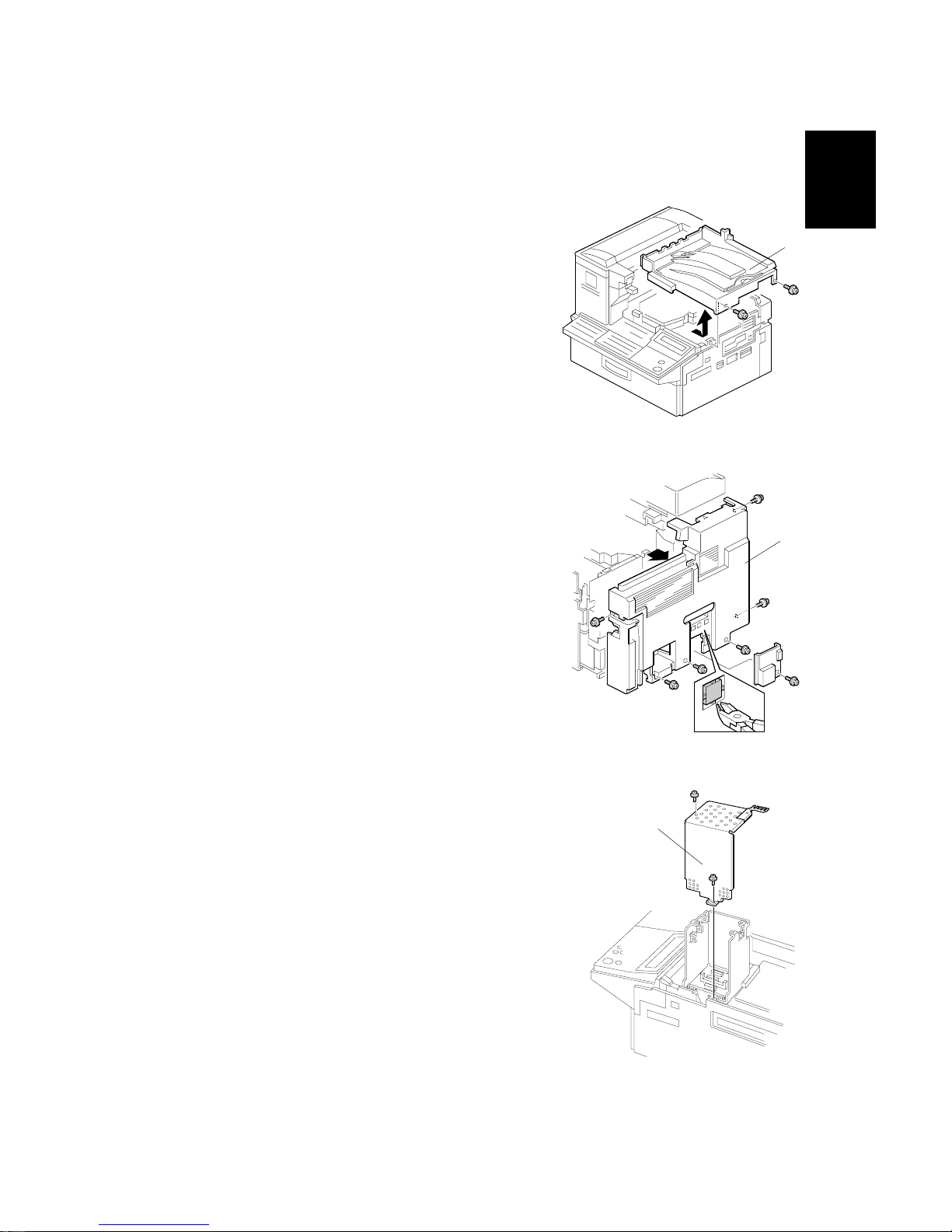
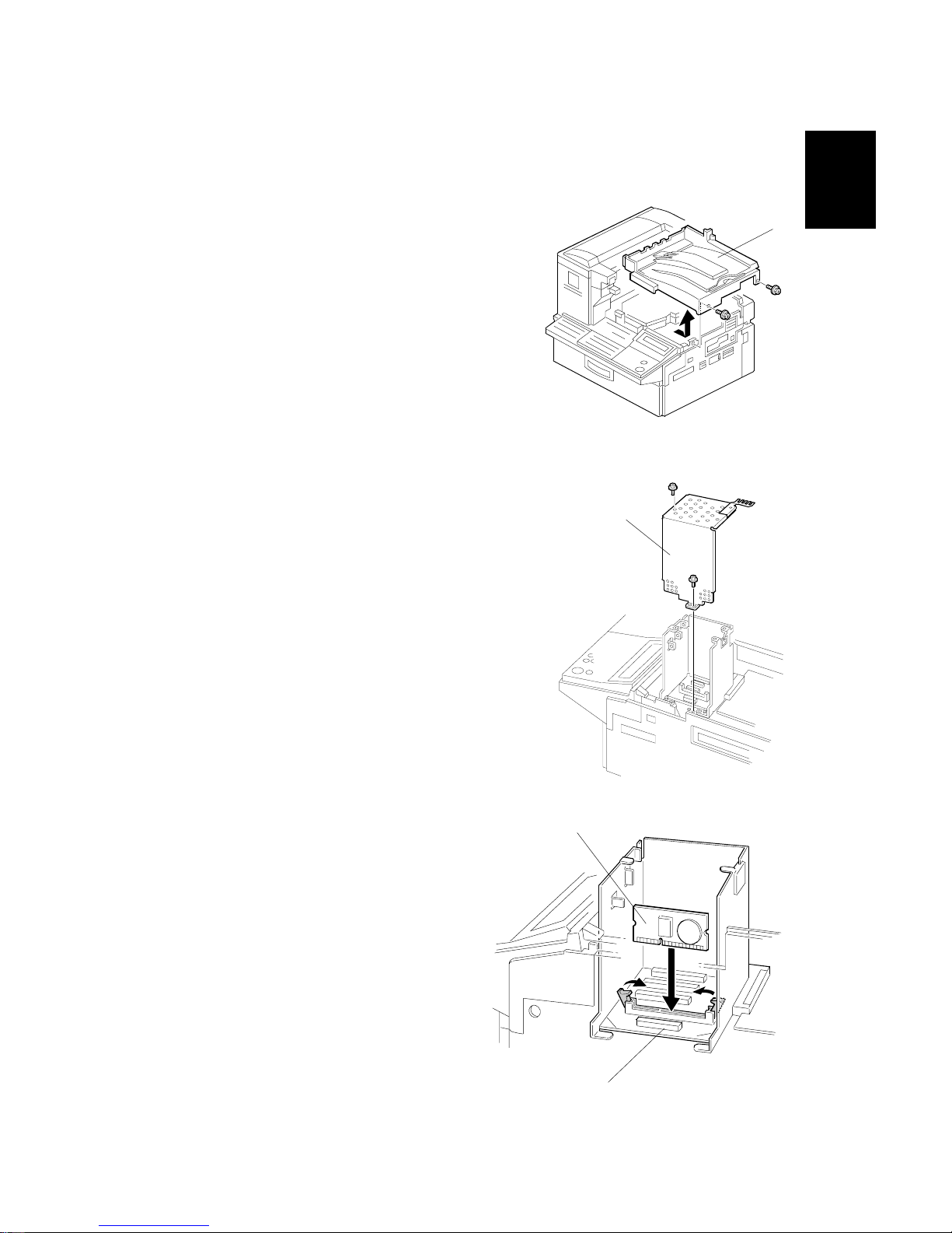
1.3.3 ISDN G4 INTERFACE UNIT TYPE 510
1. Remove the upper cover [A] (2 screws).
2. Remove the rear cover (7 screws) [B] and cut
away the ISDN small cover as shown.
3. Remove the bracket cover [C] (4 screws) as shown.
H208I006.WMF
H208I013.WMF
H208I523.WMF
[C]
[B]
[A]
Page 20
INSTALLING OPTIONAL UNITS 14 June, 2002
1-10
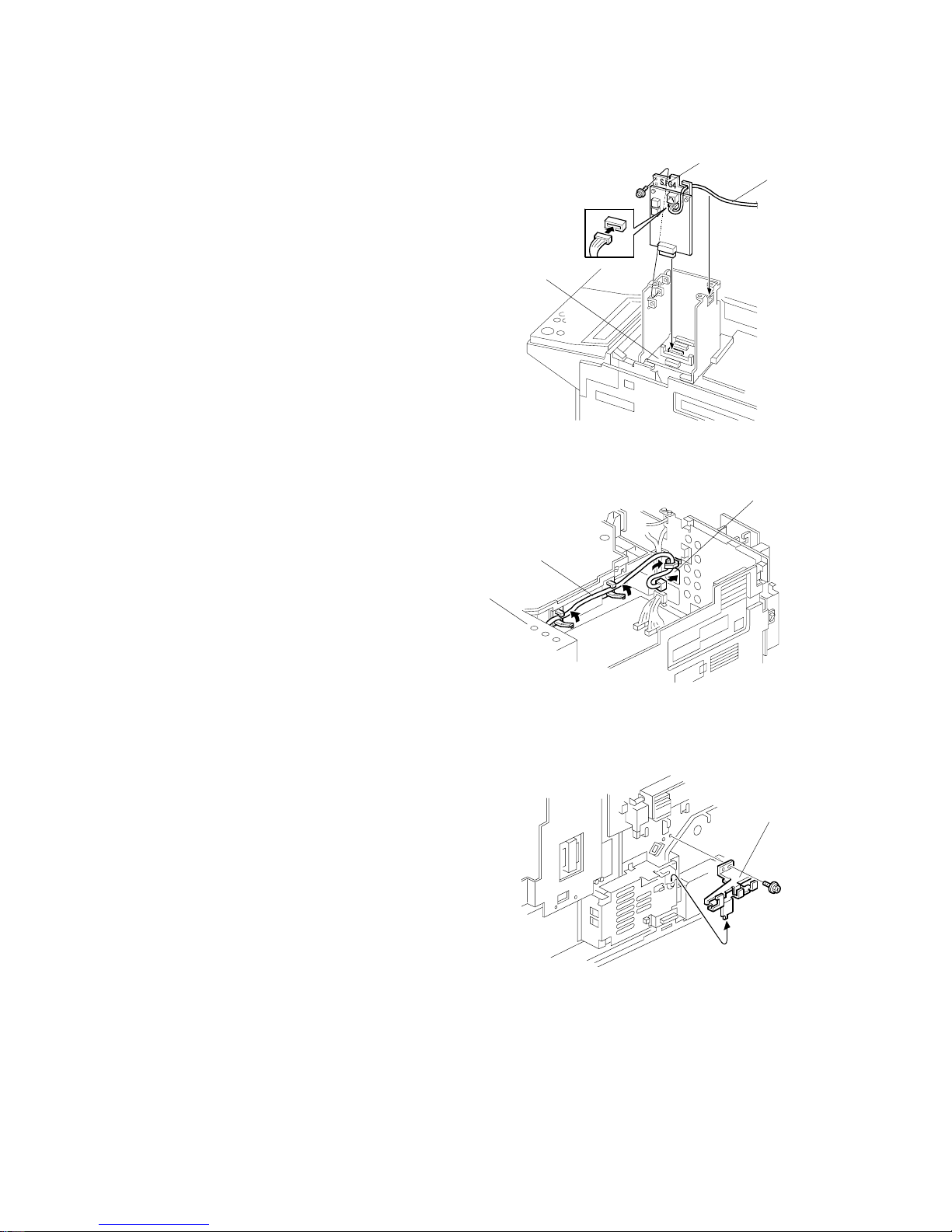
4. Connect the harness [D] to the SiG4 board
[E] and insert the board into the SiG4
connector on the OPIF board [F].
5. Reattach the bracket cover [C], then lead
the harness [D] through the 3 clamps and
the hole [G] in the rear bracket as shown.
6. Remove the bracket assembly [H] from
rear side of the machine as shown.
H208I019.WMF
H208I020.WMF
H208I040.WMF
[D]
[F]
[D]
[H]
[E]
[C]
[G]
Page 21
14 June, 2002 INSTALLING OPTIONAL UNITS
1-11
Installation
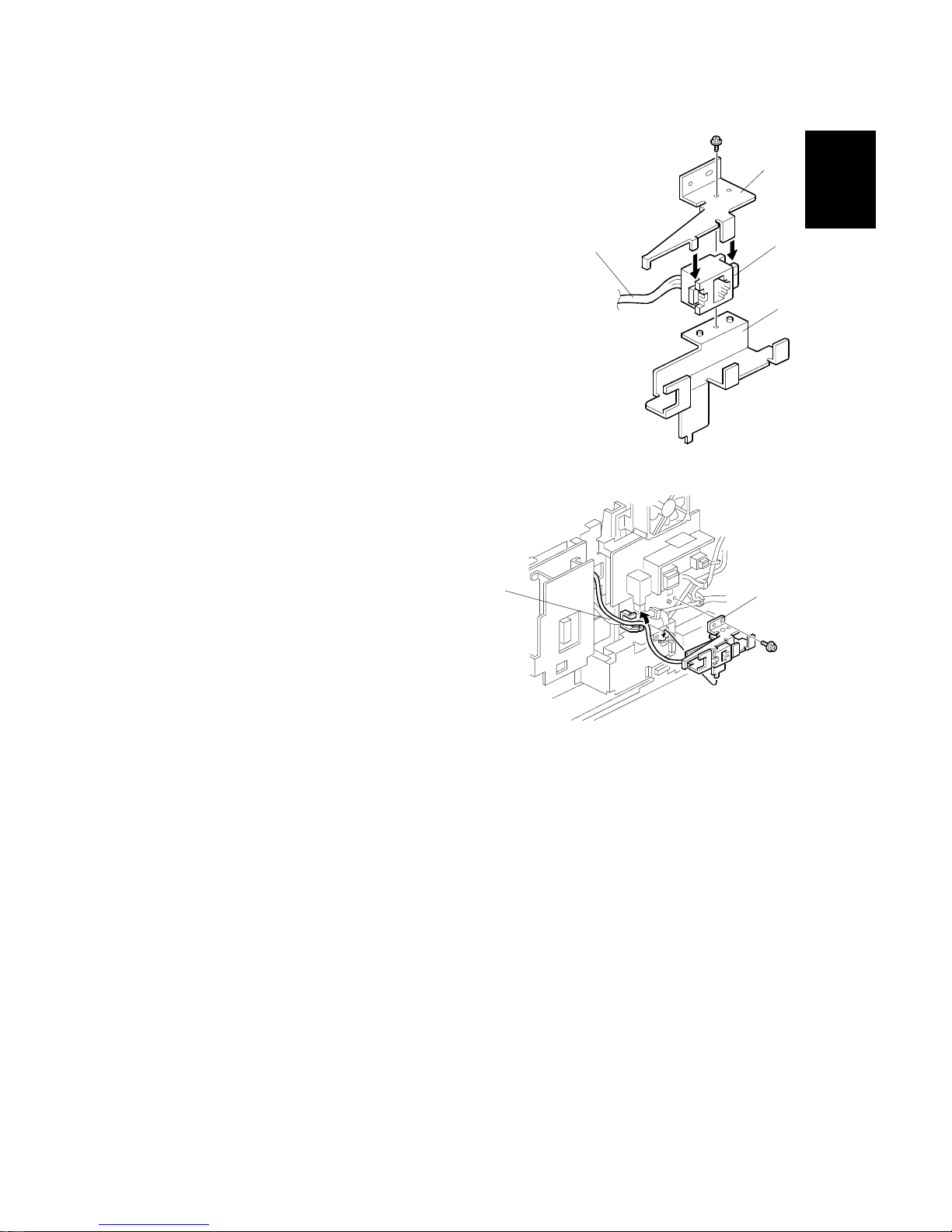
7. Attach the bracket [I] to the connector [J] on the
harness [D] from the unit kit. Then, attach them to
bracket [K] as shown.
8. Clamp the harness [D] from Step 7 as
shown, then attach the bracket assembly [L]
to the machine (1 screw).
9. Reattach the rear and upper covers.
14. Plug in the machine and turn on the main power switch.
15. Enter Service mode and set bit 2 of communication switch 16 to “1”.
16. Exit Service mode and turn off the machine, then turn the machine back on.
17. Print the System Parameter List from inside Service mode, and make sure that
“G4” is listed as an option. Then exit Service mode.
10. Set up and program the items required for ISDN communications:
To connect to the US National ISDN network, it is necessary to also input the
SPID (Service Profile ID Number).
H208I021.WMF
H208I022.WMF
[D]
[I]
[J]
[D]
[K]
[L]
Page 22
INSTALLING OPTIONAL UNITS 14 June, 2002
1-12
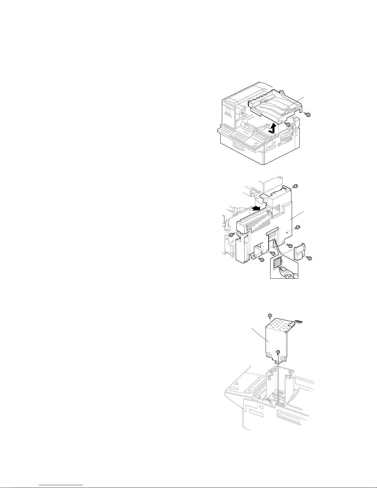
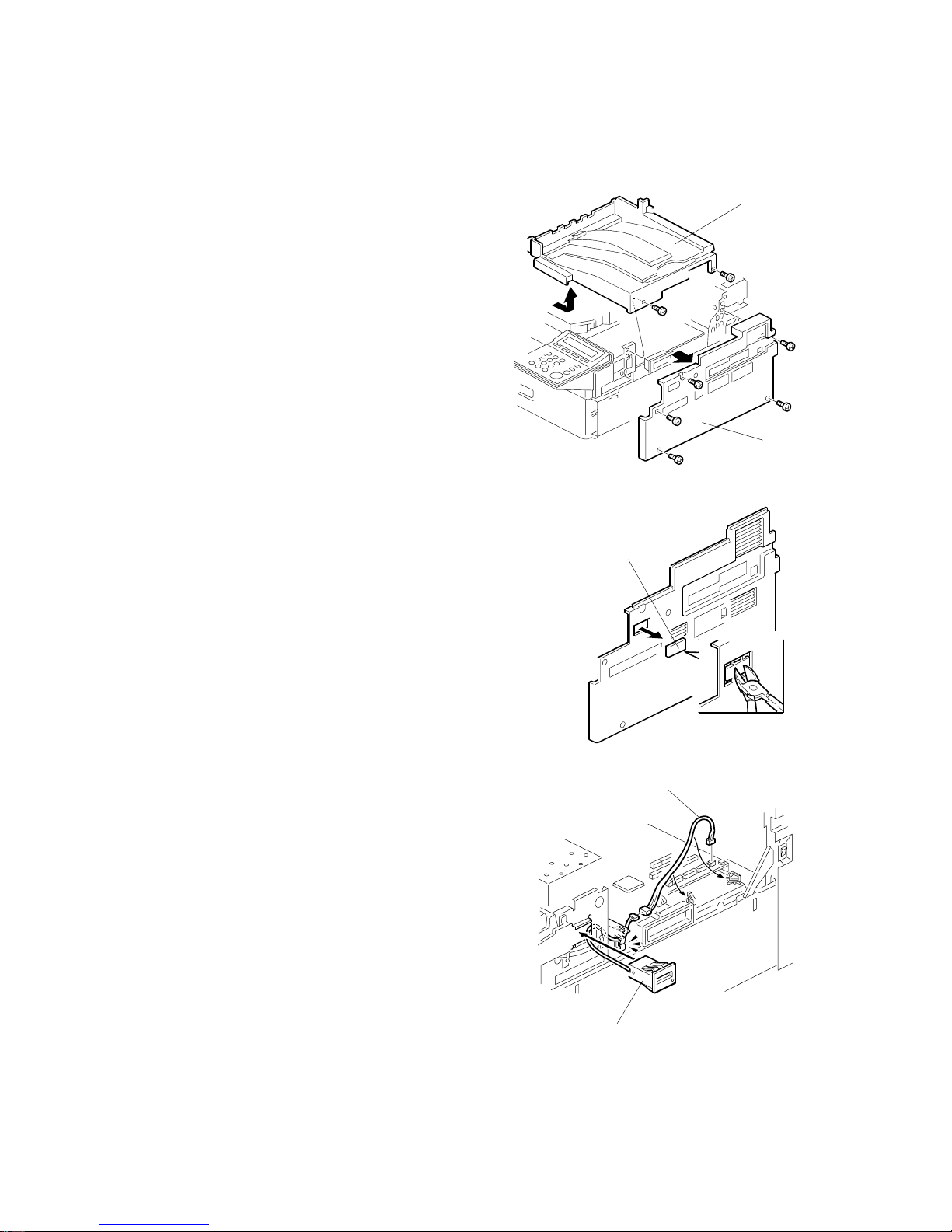
1.3.4 G3 INTERFACE UNIT TYPE510
1. Remove the upper cover [A] (2 screws).
2. Remove the rear cover (7 screws) [B] and cut
away the LINE2 small cover as shown.
3. Remove the bracket cover [C] (4 screws) as
shown.
H209I006.WMF
H209I013.WMF
H209I523.WMF
[C]
[A]
[B]
Page 23
14 June, 2002 INSTALLING OPTIONAL UNITS
1-13
Installation
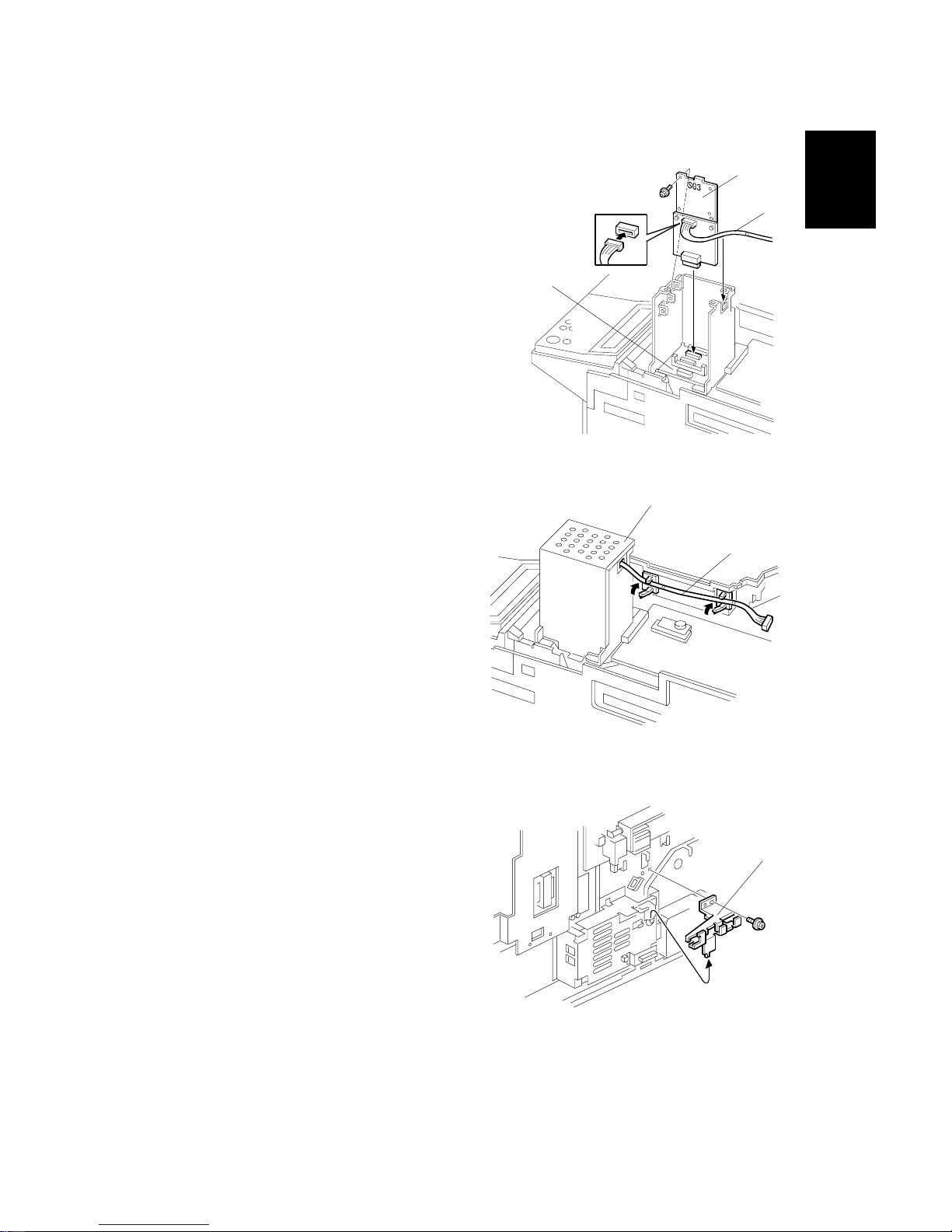
4. Connect the harness [D] to the SG3 board
[E] and insert the board into the SG3
connector on the OPIF board [F].
5. Reattach the bracket cover [C], then
lead the harness [D] through the 2
clamps as shown.
6. Remove the bracket assembly [G] from
rear side of the machine as shown.
H209I014.WMF
H209I015.WMF
H209I040.WMF
[D]
[F]
[D]
[G]
[E]
[C]
Page 24
INSTALLING OPTIONAL UNITS 14 June, 2002
1-14
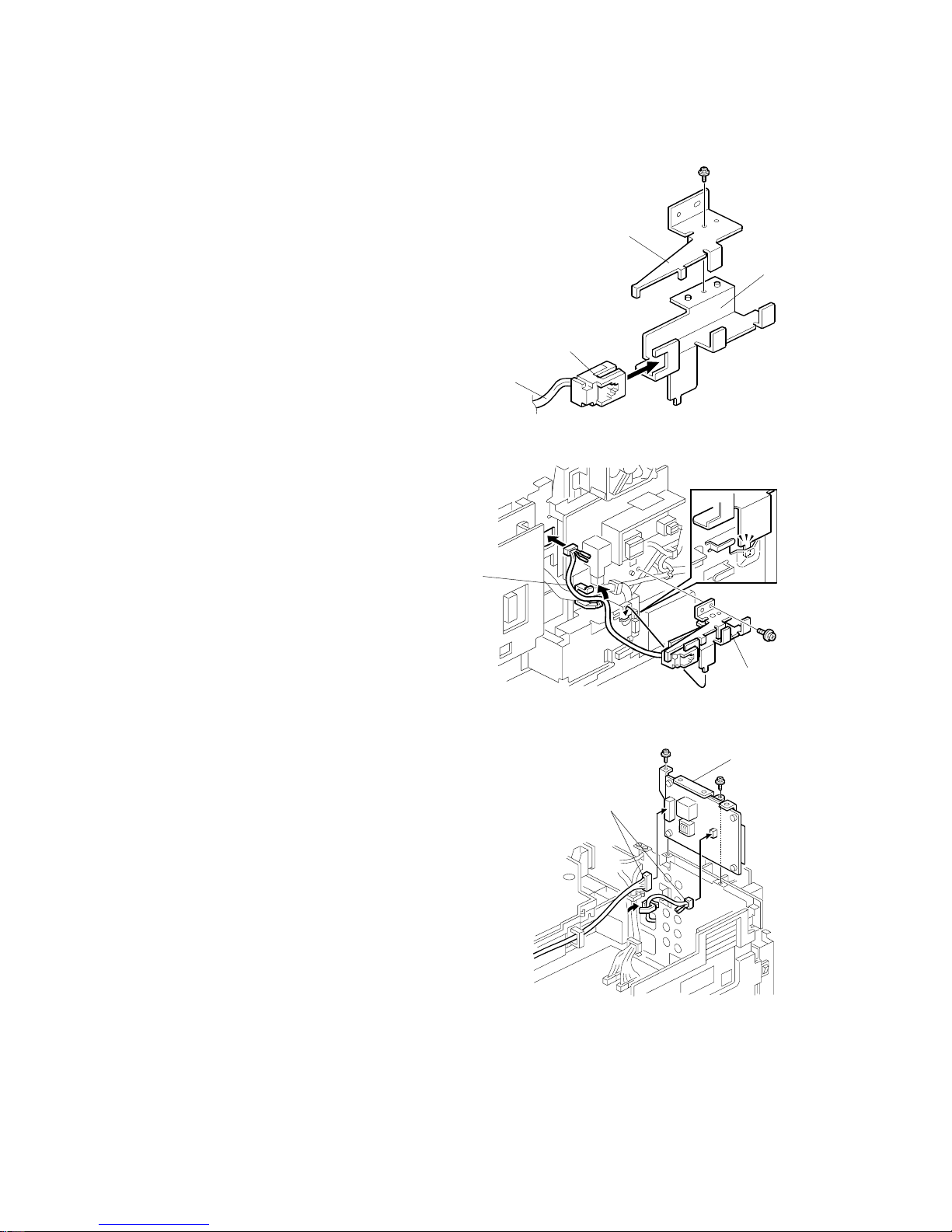
7. Attach the connector [H] of the harness [I] to
the bracket [J] and secure the bracket [K] (1
screw).
8. Lead the harness [I] from Step 7 through
the clamp and hole in the bracket as
shown. Then, attach the bracket
assembly [L] to the rear side of the
machine (1 screw).
9. Attach the NCU board [M] to the machine as
shown (2 screws), then connect the 2
harnesses [N] to the NCU board.
10. Replace the rear and upper covers.
11. Plug in the machine and turn on the main
power switch.
12. Enter Service mode and set bit 1 of
communication switch 16 to “1”.
13. Exit Service mode and turn off the machine,
then turn the machine back on.
14. Print the System Parameter List from inside
Service mode, and make sure that “G3” is
listed as an option. Then exit Service mode.
15. Set up and program the items required for PSTN-2 communication.
H209I016.WMF
H209I017.WMF
H209I018.WMF
[H]
[J]
[I]
[L]
[I]
[K]
[M]
[N]
Page 25
14 June, 2002 INSTALLING OPTIONAL UNITS
1-15
Installation
1.3.5 FAX ON DEMAND TYPE 510
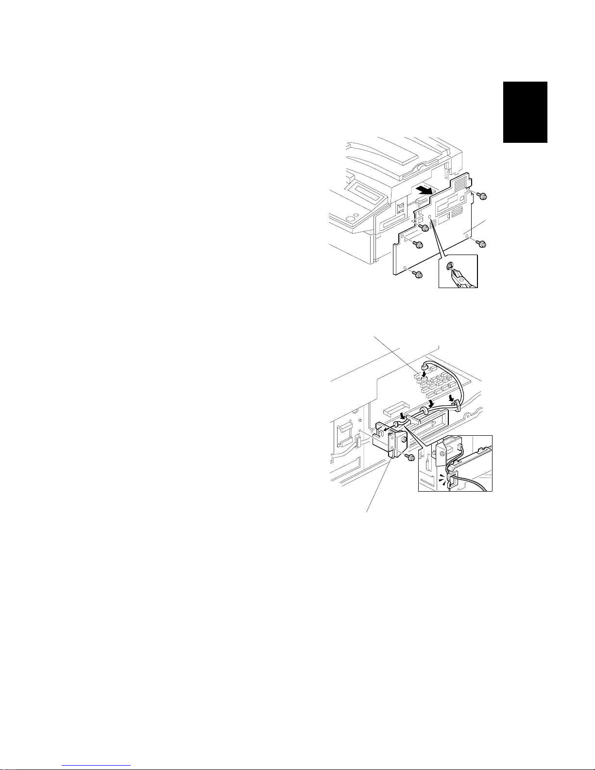
1. Remove the right cover [A] (5 screws) and
small cut-out as shown.
2. Attach the FOD unit [B] (1 screw) to the
right side of the machine. Then, lead the
harness through the clamps and connect it
to CN53 [C] on the FCU board.
H213I026.WMF
H213I055.WMF
[A]
[B]
[C]
Page 26
INSTALLING OPTIONAL UNITS 14 June, 2002
1-16
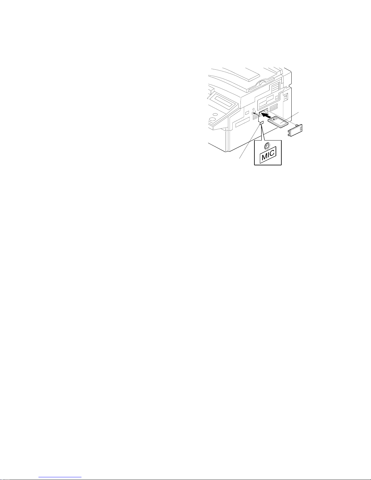
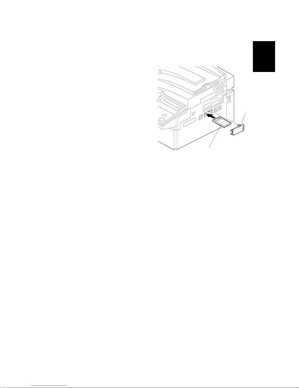
3. Reattach the right cover and insert the IC
card [D] as shown. Then affix the “MIC”
decal [E] on the right cover.
4. Plug in the machine and turn on the main power switch.
5. Print the System Parameter List from inside Service mode, then make sure that
“FOD” is listed as an option. Then exit Service mode.
6. Remind the user to connect the microphone from the FOD kit whenever using
Fax On Demand.
H213I028.WMF
[D]
[E]
Page 27
14 June, 2002 INSTALLING OPTIONAL UNITS
1-17
Installation
1.3.6 FUNCTION UPGRADE UNIT TYPE 510
1. Remove the upper cover [A] (2 screws).
2. Remove the bracket cover [B] (4 screws) as
shown.
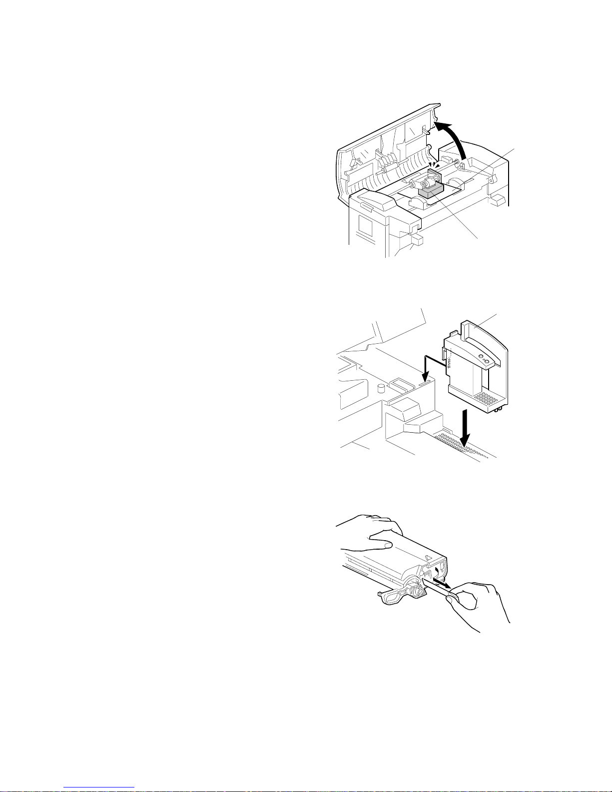
3. Insert the Function Upgrade Unit [C]
into CN3 on the OPIF board [D].
4. Replace the bracket cover and upper
cover.
5. Plug in the machine and turn on the
main power switch.
6. Print the System Parameter List from
inside Service mode, and make sure
that “FUNCTION BOARD” is listed as
an option. Then exit Service mode.
H214I006.WMF
H214I523.WMF
H214I041.WMF
[B]
[D]
[A]
[C]
Page 28
INSTALLING OPTIONAL UNITS 14 June, 2002
1-18
1.3.7 COUNTER TYPE 510
1. Remove the top cover [A] (2 screws)
and right cover [B] (5 screws).
2. Cut away the small cover [C].
3. Attach the counter [D] on the machine,
then connect relay harness [E] (contained
in the kit) to the counter harness.
4. Connect the relay harness [E] to CN52 on
the FCU board, then clamp the harness.
5. Replace the top and the right covers.
6. Make some copies and check whether or
not the counter is working correctly. If it is
not, check the connection of the FCUcounter harness.
H230I003.WMF
H230I501.WMF
H230I530.WMF
[A]
[B]
[C]
[D]
[E]
Page 29
14 June, 2002 INSTALLING OPTIONAL UNITS
1-19
Installation
1.3.8 FEATURE EXPANDER TYPE 300 40M
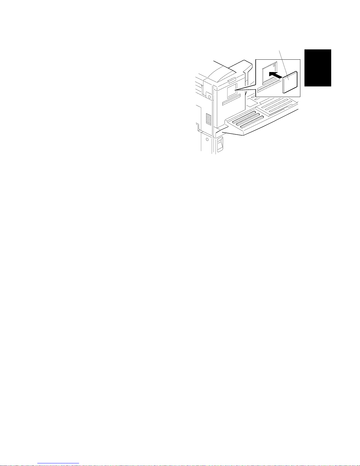
1. Remove the small cover [A] on the right
cover.
2. Insert the 40MB memory card [B] into
the machine.
3. Reattach the small cover.
4. Print the System Parameter List from inside Service mode, then make sure that
“40MB” is listed as an option. Then exit Service mode.
H215I003.WMF
[A]
[B]
Page 30
14 June, 2002 SPECIAL TOOLS AND LUBRICANTS
2-1
Preventive
Maintenance
2. PREVENTIVE MAINTENANCE
2.1 SPECIAL TOOLS AND LUBRICANTS
• Flash memory card -4M (P/N: N8036701)
• Flash/SRAM data copy tool (P/N: A1939353/H5159100)
2.2 PM TABLE
Scanner/ADF
Item 30K 60K 120K 180K Notes
Pick-Up Roller Ass’y
(Including Feed Roller)
R (user) R (user) R (user) R (user) ADF Maintenance Kit
Reverse Roller R (user) R (user) R (user) R (user) ADF Maintenance Kit
Exposure Glass C (user) C (user) C (user) C (user) Soft cloth and water
R0, R1 and R2 Rollers C (user) C (user) C (user) C (user) Soft cloth and water
Pressure Roller C (user) C (user) C (user) C (user) Soft cloth and water
White Shading Plate C (user) C (user) C (user) C (user) Soft cloth and water
Printer
Item 30K 60K 120 180K Notes
Fusing Unit - R (user) R (user) R (user)
Fusing Maintenance
Kit
Transfer Roller - R (user) R (user) R (user)
Fusing Maintenance
Kit
Paper Feed Roller - - - R (FST)
Registration Roller - C (user) C (user) C (user) Soft cloth and water
Paper Feed Unit (Optional)
Item 30K 60K 120K 180K Notes
Feed Roller - - - R (FST)
FST: Field Service Technician
C: Clean, R: Replace
NOTE: After replacing a maintenance kit, make sure to reset the appropriate PM
counter through the Key Operator Tools menu (User Tools – Key Operator
Tools – System Settings – Reset PM Counter).
Page 31

14 June, 2002 EXTERNAL COVERS
3-1
Replacement
Adjustment
3. REPLACEMENT AND ADJUSTMENT
3.1 EXTERNAL COVERS
3.1.1 REMOVING THE ADF FRONT AND REAR COVERS
1. Open the ADF upper cover [A].
2. Remove the ADF front cover [B] (! x 2).
3. Remove the pick-up roller unit [C] by sliding the unit toward the back (toward
the spring-loaded end).
4. Remove the ADF rear cover [D] (! x 1).
3.1.2 REMOVING THE UPPER GUIDE PLATE
1. Remove the upper guide plate [A] (! x 4).
H310R001.WMF
H310R002.WMF
[A]
[B]
[C]
[D]
[A]
Page 32

EXTERNAL COVERS 14 June, 2002
3-2
3.1.3 REMOVING THE REAR COVER
1. Remove the optional connector cover [A] (! x 1).
2. Remove the rear cover [B] (! x 6).
H310R006.WMF
[A]
[B]
Page 33

14 June, 2002 EXTERNAL COVERS
3-3
Replacement
Adjustment
3.1.4 REMOVING THE OPERATION PANEL AND FRONT COVER
1. Remove the upper cover [A] (! x 2).
2. Remove the right cover [B] (! x 5).
3. Remove the front upper cover [C] (! x 2).
4. Remove the operation panel [D] (! x 3, " x 1).
5. Pull out the cassette [E].
6. Remove the front lower cover [F] (! x 5).
H310R003.WMF
H310R004.WMF
H310R005.WMF
[A]
[B]
[C]
[D]
[E]
[F]
Page 34

ADF/SCANNER SECTIONS 14 June, 2002
3-4
3.2 ADF/SCANNER SECTIONS
3.2.1 REPLACING THE PICK-UP ROLLER (PART OF THE ADF
MAINTENANCE KIT)
1. Open the ADF upper cover [A].
2. Remove the pick-up roller unit [B].
NOTE: Slide the unit toward the rear (toward the spring-loaded end). The front
bushings will detach and the unit can then be removed.
NOTE: If you install all parts in the ADF maintenance kit at the same time, be sure
to reset the PM counter (ADF).
3.2.2 REPLACING THE FEED ROLLER (PART OF THE ADF
MAINTENANCE KIT)
First, do the first two steps of the pick-up roller replacement procedure above.
1. Release the pick-up roller stopper [C] and pull the shaft toward the end with the
E-clip [D]. This will allow the pick-up roller to be removed.
2. Remove the three E-clips from the feed roller [E].
3. Release the roller clutch stoppers [F], pull out the shaft [G], and remove the
feed roller.
NOTE: If you install all parts in the ADF maintenance kit at the same time, be sure
to reset the PM counter (ADF).
H310R001.WMF
H310R025.WMF
[A]
[B]
[C]
[D]
[E]
[F]
[G]
Page 35

14 June, 2002 ADF/SCANNER SECTIONS
3-5
Replacement
Adjustment
3.2.3 REPLACING THE REVERSE ROLLER AND TORQUE
LIMITER (PART OF THE ADF MAINTENANCE KIT)
1. Remove the separation roller cover [A].
2. Remove the clip [B] and replace the reverse roller [C] and torque limiter [D].
NOTE: If you install all parts in the ADF maintenance kit at the same time, be sure
to reset the PM counter (ADF).
H310R050.WMF
H310R051.WMF
[A]
[B]
[C]
[D]
Page 36

ADF/SCANNER SECTIONS 14 June, 2002
3-6
3.2.4 REPLACING THE R0 ROLLER
1. Remove the ADF rear cover (☛ 3.1.1).
2. Remove the ADF front cover (☛ 3.1.1).
3. Remove the upper guide plate [A] (! x 4).
4. Remove the belt tension roller with spring plate [B] (! x 1).
5. Remove the belt [C].
6. Release the pawl that holds the pulley [D], and remove the pulley.
7. Slide the R0 roller [E] toward the rear and lift the roller out.
H310R002.WMF
H310R950.WMF
[A]
[B]
[C]
[D]
[E]
Page 37

14 June, 2002 ADF/SCANNER SECTIONS
3-7
Replacement
Adjustment
3.2.5 REPLACING THE R1, R2 AND DOCUMENT EXIT ROLLERS
1. Remove the ADF rear cover (☛ 3.1.1).
2. Remove the ADF front cover (☛ 3.1.1).
3. Remove the rear cover (☛ 3.1.3).
4. Remove the ADF lower cover [A] (! x 1).
5. Remove the belt [B].
6. Remove the scanner motor bracket and scanner motor [C] (! x 3).
H310R959.WMF
[A]
[B]
[C]
Page 38

ADF/SCANNER SECTIONS 14 June, 2002
3-8
7. Remove the white plate [D]. This is done by first sliding the plate toward the
front of the machine, then releasing and removing the rear pawl.
8. Remove the screw [E] that fastens the grounding strip.
9. Remove the guide plate [F] (! x 5).
10. Remove the gears [G], [H], [I], and [J] (first remove the gear pawls).
11. Remove the clips and bushings, followed by the R1 [K] and R2 [L] rollers, and
the exit roller [M].
H310R029.WMF
H310R953.WMF
[G]
[H]
[I]
[J]
[K]
[L]
[M]
[D]
[E]
[F]
Page 39

14 June, 2002 ADF/SCANNER SECTIONS
3-9
Replacement
Adjustment
3.2.6 REPLACING THE CIS (CONTACT IMAGE SENSOR)
(SCANNER)
1. With the ADF open, remove the R1 roller guide [A] (! x 2) and exit guide [B] (!
x 2).
2. Remove the CIS [C] (! x 2, " x 1).
H310R007.WMF
H310R008.WMF
[A]
[B]
[C]
Page 40

ADF/SCANNER SECTIONS 14 June, 2002
3-10
3.2.7 REMOVING THE STAMP UNIT
1. With the ADF open, remove the exit guide (! x 2) (☛ 3.2.6).
2. Replace the stamp unit (! x 1).
NOTE: When removing the stamp unit, ensure that ink does not leak out of it.
3.2.8 ADJUSTING THE SCANNING TOP MARGIN
To adjust the scanner home position, change the following RAM data. When the
value is increased (with respect to the default value), the image on the printed copy
moves down the page.
ADF scanning:
Address: 4049C4 to 4049C5 default value: 004FH Unit: 0.1 mm
Adjustable range: 0000 to 009EH
MDF scanning
Address: 4049C6 to 4049C7 default value: 004FH Unit: 0.1 mm
Adjustable range: 0000 to 009EH
H310R009.WMF
Page 41

14 June, 2002 LASER UNIT
3-11
Replacement
Adjustment
3.3 LASER UNIT
!
WARNING
Before attempting any of the procedures in this secti on, turn off the main
switch, unplug the machine, and remove the AIO cartridge. Laser beams
can seriously damage your eyes.
3.3.1 REPLACING THE LASER SYNCHRONIZATION DETECTOR
AND LD UNITS
1. Remove the exit guide (☛ 3.2.6).
2. Remove two brackets [A] (! x 1 each).
3. Remove the upper cover (☛ 3.1.4).
4. Remove the bracket [B] (! x 1).
5. Remove the LD unit [C] (! x 5, " x 3).
Loosen the two screws in the back of the machine by inserting a screwdriver
through the two openings.
DECAL6.WMF
H310R010.WMF
H310R011.WMF
[A]
[B]
[C]
Page 42

LASER UNIT 14 June, 2002
3-12
6. Remove the laser synchronization detector [A] (! x 1).
7. Remove the LD unit [B] (! x 1).
3.3.2 REPLACING THE POLYGON MOTOR
1. Remove the laser unit cover (! x 5).
2. Remove the polygon motor [A] (! x 4, " x 1).
H310R954.WMF
H310R955.WMF
[A]
[B]
[A]
Page 43

14 June, 2002 LASER UNIT
3-13
Replacement
Adjustment
3.3.3 ADJUSTING THE PRINTING SIDE-TO-SIDE REGISTRATION
Adjust the laser beam main scan start position when the offset is large. The
procedure is as follows:
1. Make copies using the mainframe cassette, bypass feeder, and optional paper
feed units and check the amount that the image is shifted.
2. Adjust by changing the contents of the following addresses:
Source Address Default Unit
Main Frame 402466 0002H 0.5 mm
1st Optional Unit 402468 0000H 0.5 mm
2nd Optional Unit 40246A 0000H 0.5 mm
3rd Optional Unit 40246C 0000H 0.5 mm
4th Optional Unit 40246E 0000H 0.5 mm
By-pass Feeder 402470 0004H 0.5 mm
3. To move the start position to the right, increase the value.
To move the start position to the left, decrease the value.
For example:
• To move the start position to the right 2 mm (with respect to the default
value):
0002H + (2 / 0.5) H = 0006H
• To move the start position to the left 1 mm (with respect to the default value):
0002H - (1 / 0.5) H = 0000H
Page 44

AIO CARTRIDGE 14 June, 2002
3-14
3.4 AIO CARTRIDGE
3.4.1 REPLACING THE AIO CARTRIDGE
1. Open the (mainframe) left cover [A].
2. Tilt the AIO cartridge [B] upward slightly (to prevent it from touching other parts)
and remove the unit from the machine.
H310R956.WMF
[A]
[B]
Page 45

14 June, 2002 AIO CARTRIDGE
3-15
Replacement
Adjustment
3.4.2 REPLACING THE TRANSFER ROLLER (PART OF THE
FUSING MAINTENANCE KIT)
1. Open the transfer roller cover [A] as shown in the illu stration (note the direction
of the arrow).
2. While holding both ends of the roller (by the green gears on each end), lift and
remove the roller [B].
NOTE: 1) Do not touch the surface of the roller. Oils from the skin stuck on the
roller surface may result in roller failure.
2) If you install all parts in the fusing maintenance kit at the same time,
be sure to clear the PM counter (Fusing Unit).
H310R966.WMF
[A]
[B]
Page 46

AIO CARTRIDGE 14 June, 2002
3-16
3.4.3 REPLACING THE POWER PACK
1. Remove the rear cover. (☛ 3.1.4)
2. Remove the power pack [A] (! x 2 , " x 4).
!CAUTION
When removing the power pack, make sure to first turn off the main power
and unplug the power cord. This is done to eliminate the risk of electrical
shock.
H310R957.WMF
[A]
Page 47

14 June, 2002 PAPER FEED AND REGISTRATION
3-17
Replacement
Adjustment
3.5 PAPER FEED AND REGISTRATION
3.5.1 REPLACING THE PAPER FEED ROLLER
1. Open the left cover [A].
2. Remove the guide plate [B] (! x 2).
3. Remove the paper feed rollers [C] (# x 2).
H310R036.WMF
H310R026.WMF
[C]
[A]
[B]
Page 48

PAPER FEED AND REGISTRATION 14 June, 2002
3-18
3.5.2 REPLACING THE REGISTRATION ROLLER
1. Remove the rear cover. (☛ 3.1.3.)
2. Loosen the screws for the paper feed drive bracket [A].
3. Release the small pawl on the tip of the clutch [B] and remove the clutch.
4. Release and rotate the collar [C], then remove it along with the bushing.
5. Open the left side cover.
6. Remove the registration guide plate [D].
7. Remove the clip [E] (rear side).
8. Slide the registration roller toward the rear (left in the illustration). Once the
front side is freed, pull it up toward you and remove the roller.
H310R021.WMF
[A]
[B]
[C]
[D]
[E]
Page 49

14 June, 2002 PAPER FEED AND REGISTRATION
3-19
Replacement
Adjustment
3.5.3 ADJUSTING THE PRINTING TOP MARGIN
Adjust the start position at the top of the page when the offset is large. The
procedure is as follows:
1. Make copies using the mainframe cassette, bypass feeder, and optional paper
feed units and check the amount that the image is shifted.
2. Adjust by changing the contents of the following addresses:
Source Address Default Unit
Main Frame 40245A FFFEH 0.5 mm
1st Optional Unit 40245C FFFCH 0.5 mm
2nd Optional Unit 40245E FFFCH 0.5 mm
3rd Optional Unit 402460 FFFCH 0.5 mm
4th Optional Unit 402462 FFFCH 0.5 mm
By-pass Feeder 402464 FFFCH 0.5 mm
3. To lower the start position, increase the default value.
To raise the start position, reduce the default value.
For example:
• To lower the start position by 2 mm (with respect to the default value):
0000H + (2 / 0.5) H = 0004H
Page 50

SENSORS 14 June, 2002
3-20
3.6 SENSORS
3.6.1 REPLACING THE ADF/MDF SENSORS AND SWITCHES
1. Open the ADF upper cover. (☛ 3.1.1.)
2. Remove the ADF front cover (! x 2).
3. Remove the pickup-roller unit.
4. Remove the ADF rear cover (! x 1).
5. Remove the upper guide plate (! x 4). (☛ 3.1.2.)
6. Release the pawls of the S1 [A], B4 [B], A3 [C] sensors (at the connector sides)
and remove the sensors (" x 1 each).
7. Release and remove the pawl located on the rear face of the ADF upper cover
switch [D] (" x 1).
H310R903.WMF
[A]
[B]
[C]
[D]
Page 51

14 June, 2002 SENSORS
3-21
Replacement
Adjustment
8. Remove the sensor bracket [A] (! x 1).
9. Remove the S2 sensor [B] (" x 1).
10. Remove the ADF lower cover (! x 1). (☛ 3.2.5.)
11. Remove the ADF unit switch [C] (" x 1).
12. Remove the rear cover (☛ 3.1.3).
13. Open the ADF unit.
14. Remove the ADF lower guide plate [D] (! x 4).
15. Release the MDF S1 [E], B4 [F], A3 [G] sensor pawls and remove the sensors
(" x 1 each).
NOTE: If the rear cover is not rem oved, damage will result when opening the
ADF.
H310R022-2.WMF
H310R904.WMF
[A]
[B]
[C]
[D]
[E]
[F]
[G]
Page 52

SENSORS 14 June, 2002
3-22
3.6.2 REPLACING THE PAPER-END LED BOARD AND PAPER
SIZE SENSOR SWITCH
1. Pull the paper feed tray.
2. Remove the cover [A] (! x1).
3. Remove the paper end LED board [B] (" x 1).
4. Remove the paper size sensor switch [C] (" x 1).
H310R911.WMF
[A]
[B]
[C]
Page 53

14 June, 2002 SENSORS
3-23
Replacement
Adjustment
3.6.3 REPLACING THE PAPER NEAR END SENSOR
1. Remove the paper feed tray (! x 2).
2. Remove the guide plate (! x 2)
3. Remove the paper near end sensor [A] (" x 1)
3.6.4 REPLACING THE UPPER LIMIT AND PAPER END SENSORS
1. Remove the paper feed tray (! x 2).
2. Remove the connectors attached to the upper limit sensor [A] and paper end
sensor [B].
3. Remove the screw that holds the sensor bracket [C] in place, and remove the
bracket by pulling downward.
4. Remove the sensors from the bracket.
H310R915.WMF
H310R914.WMF
[A]
[A]
[B]
[C]
Page 54

SENSORS 14 June, 2002
3-24
3.6.5 REPLACING THE AIO CARTRIDGE SENSOR
1. Remove the upper cover (! x 2). (☛ 3.1.4)
2. Remove the right cover (☛ 3.1.4).
3. Remove the screw that fastens the AIO cartridge sensor bracket [A].
4. Remove the AIO cartridge sensor [B] from the bracket (" x 1).
NOTE: This procedure is easier to perform if the AIO cartridge is first removed.
Be sure to put the AIO cartridge sensor back in the original position.
H310R907.WMF
[A]
[B]
Page 55

14 June, 2002 SENSORS
3-25
Replacement
Adjustment
3.6.6 REPLACING THE PAPER EXIT SENSOR
1. Remove the upper cover (! x 2). (☛ 3.1.4)
2. Remove the front upper cover (☛ 3.1.4)
3. Remove the connectors of the paper exit sensor.
4. While holding up the actuator [A] of the paper exit sensor, release the front
pawl and remove the paper exit sensor [B].
H310R905.WMF
[A]
[B]
Page 56

SENSORS 14 June, 2002
3-26
3.6.7 REPLACING THE TONER END SENSOR
1. Open the left cover [A].
2. Remove the AIO cartridge [B].
3. Remove the pawls on both sides of the toner end sensor [C] and remove the
sensor (" x 1).
H310R956.WMF
H310R958.WMF
[A]
[B]
[C]
Page 57

14 June, 2002 SENSORS
3-27
Replacement
Adjustment
3.6.8 REPLACING THE REGISTRATION SENSOR
1. Open the left cover.
2. Lift up the registration guide.
3. While the registration guide is held up, remove the sensor cover by releasing
the pawl of the registration sensor cover [A].
4. Release the pawl of the registration sensor and remove the sensor [B] from the
cover (" x 1).
H310R022.WMF
[A]
[B]
Page 58

FUSING UNIT 14 June, 2002
3-28
3.7 FUSING UNIT
3.7.1 REPLACING THE FUSING UNIT (PART OF THE FUSING
MAINTENANCE KIT)
1. Open the left cover [A].
2. Remove the stopper screw (green) located below the rear side lever [B]
(brown).
3. Push down levers [B].
4. Remove the fusing unit [C].
!CAUTION
1. Since the temperature of the fusing unit is very high, exercise caution
to avoid being burned.
2. If you install all parts in the fusing maintenance kit at the same time, be
sure to clear the PM counter (Fusing Unit).
H310R952.WMF
[A]
[B]
[C]
Page 59

14 June, 2002 FUSING UNIT
3-29
Replacement
Adjustment
3.7.2 DISASSEMBLING THE FUSING UNIT
1. Remove the fusing unit cover [A] (! x 2).
2. Remove two springs [B] and two support plates [C] (! x 2).
3. Disassemble the fusing unit (! x 2).
H310R013.WMF
H310R015.WMF
[A]
[A]
[B]
[C]
[B]
[C]
Page 60

FUSING UNIT 14 June, 2002
3-30
3.7.3 REPLACING THE PRESSURE ROLLER
1. Remove the two bushings [A], two metal levers [B] and the two levers [C].
2. Remove the pressure roller.
NOTE: The marked end of the roller [D] must be at the front side of the machine.
H310R017.WMF
H310R018.WMF
[A]
[B]
[C]
[D]
[B]
[A]
[C]
Page 61

14 June, 2002 FUSING UNIT
3-31
Replacement
Adjustment
3.7.4 REPLACING THE HOT ROLLER, FUSING LAMP, AND
THERMOFUSE
1. Remove the hot roller stripper springs and the grounding plate [A] (! x 1).
2. Remove the fusing lamp [B] (! x 2), bushings, and hot roller [C].
3. Remove the thermofuse [D] (! x 4).
H310R019.WMF
[A]
[B]
[C]
[D]
Page 62

FUSING UNIT 14 June, 2002
3-32
3.7.5 REPLACING THE THERMISTOR
1. Remove the cable terminal [A] (! x 3).
2. Remove the thermistor [B] (! x 1).
H310R028.WMF
[A]
[B]
Page 63

14 June, 2002 FUSING UNIT
3-33
Replacement
Adjustment
3.7.6 REPLACING THE HOT ROLLER STRIPPERS
1. Disconnect the springs [A].
2. Remove the two outer exit rollers [B].
3. Release the stoppers [C] and remove the hot roller strippers [D].
H310R020.WMF
[A]
[B]
[C]
[D]
Page 64

PCBS 14 June, 2002
3-34
3.8 PCBS
3.8.1 REPLACING THE PSU
1. Remove the rear cover. (☛ 3.1.3)
2. Lift the PSU [B] out of the machine (! x 5, " x 4, 1 grounding wire [A]).
!CAUTION
When removing the PSU, make sure to first turn off the main power and
unplug the power cord. This is done to eliminate the risk of electrical
shock.
H310R951.WMF
[A]
[B]
Page 65

14 June, 2002 PCBS
3-35
Replacement
Adjustment
3.8.2 REPLACING THE OPIF/NCU/FCU
1. OPIF board
1. Remove the upper cover (☛ 3.1.4).
2. Remove the bracket cover [A] (! x 4).
3. Remove the bracket [B] (! x 4).
4. Remove the OPIF board [C] (! x 2).
H310R960.WMF
H310R961.WMF
H310R962.WMF
[A]
[B]
[C]
Page 66

PCBS 14 June, 2002
3-36
2. FCU and MBU boards
!CAUTION
Make sure to first turn off the main power and unplug the power cord. This
is done to eliminate the risk of electrical shock.
1. Remove the upper cover (☛ 3.1.4).
2. Disconnect the harnesses.
3. Remove the FCU board [A] (! x 4).
4. Remove the MBU board [B] from the old FCU and connect it to the new FCU.
If you have to replace the MBU, first try to upload the RAM data from the MBU to
an IC card, then try to download it to the new card after reassembling the machine.
Make sure that the battery switch on the MBU is at the ON position.
H310R023.WMF
[A]
[B]
Page 67

14 June, 2002 PCBS
3-37
Replacement
Adjustment
3. NCU board
!CAUTION
Make sure to first turn off the main power and unplug the power cord. This
is done to eliminate the risk of electrical shock.
1. Remove the rear cover (☛ 3.1.3).
2. Remove the relay connector bracket [A] (! x 1).
3. Remove the NCU board unit [B] (! x 3, " x 3).
H310R963.WMF
H310R964.WMF
[A]
[B]
Page 68

PCBS 14 June, 2002
3-38
3.8.3 REPLACING THE LCD CONTROLLER AND LCD BOARD
1. Remove the upper cover (☛ 3.1.4).
2. Remove the operation panel (☛ 3.1.4).
3. Remove the LCD controller board [A] (! x 23).
4. Remove the LCD board [B] (! x 4, " x 2).
H310R012.WMF
[A]
[B]
Page 69

14 June, 2002 PCBS
3-39
Replacement
Adjustment
3.8.4 REPLACING THE POWER PACK
1 Remove the rear cover (☛ 3.1.3)
2 Remove the power pack [A] (! x 2, " x 4)
H310R957.WMF
[A]
Page 70

PCBS 14 June, 2002
3-40
3.8.5 REPLACING THE COOLING FAN
1. Replace the rear cover (☛ 3.1.3)
2. Remove the cooling fan [A] (! x 2, " x 1)
NOTE: The decal on the surface of the fan [B] must be at the rear side of the
machine.
H310R024.WMF
[A]
[B]
Page 71

14 June, 2002 BYPASS FEEDER UNIT
3-41
Replacement
Adjustment
3.9 BYPASS FEEDER UNIT
3.9.1 DIS ASSEMBLING THE BYPASS FEEDER UNITS
1. Remove the unit [A] (! x 2, " x 1, 1 grounding wire)
H310R030.WMF
[A]
Page 72

BYPASS FEEDER UNIT 14 June, 2002
3-42
3.9.2 REPLACING THE CLUTCH AND PAPER FEED ROLLER
1 Remove the spring and three clips.
2 Remove the clutch [A].
3 Remove the paper feed roller [B].
H310R035.WMF
H310R034.WMF
[A]
[B]
Page 73

14 June, 2002 BYPASS FEEDER UNIT
3-43
Replacement
Adjustment
3.9.3 REPLACING THE PAPER SIZE DETECTION SWITCH
1 Remove the bypass cover [A] (! x 3)
2 Remove the dial cover [B].
3 Remove the pin [C] and dial [D].
4 Remove the switch [E] (" x 1).
H310R032.WMF
[A]
[B]
[C]
[D]
[E]
Page 74

BYPASS FEEDER UNIT 14 June, 2002
3-44
3.9.4 REPLACING THE CONNECTOR AND PAPER END SENSOR
1 Disconnect the harness (" x 2).
2 Remove the connector [A].
3 Disconnect the harness (" x 1).
4 Remove the paper end sensor [B].
H310R033.WMF
H310R031.WMF
[A]
[B]
Page 75

14 June, 2002 DATA OR FIRMWARE DOWNLOAD/UPLOAD
3-45
Replacement
Adjustment
3.10 DATA OR FIRMWARE DOWNLOAD/UPLOAD
!
CAUTION
1. Make sure to turn the power off before in serting the IC card.
2. If the optional 40MB memory card (feature expander or fax on demand)
is installed, make sure to re-install it before turning the power on in
Step 7 below. Otherwise, programmed data may be lost.
If copying the firmware onto an IC card beforehand with MCE (Memory Card
Explorer),.please confirm that the start address and firmware file are as follows:
Firmware Start address Firmware file type
MBU (FCU) 0H *. bin
SG3
SiG4
NIC-F
JPEG
200000H *. rdt / *. mdt
Page 76

DATA OR FIRMWARE DOWNLOAD/UPLOAD 14 June, 2002
3-46
3.10.1 DATA COPY BETWEEN THE IC CARD AND MACHINE
Use the following procedure to copy data between the IC card and mainframe.
1. Turn the main power OFF. Then, insert the IC card into the IC card slot on right
side of the machine.
NOTE: The IC card should be oriented with the “A” side facing up, as shown.
2. Turn the main power ON.
If the menu does not appear, enter
service mode and use service function
12
3. Select the appropriate item.
NOTE: To copy optional firmware,
scroll down using the “DOWN”
key.
4. Press Start.
5. If “OK” is displayed, exit the function and turn the power OFF.
If “NG!!” is displayed, repeat from step 1.
6. Remove the IC card, re-insert the 40MB memory card (if present) and reattach
the small cover.
7. After uploading firmware: Turn the main power back ON and check the ROM
version in Service mode (Function 23).
H310R965.WMF
H310R501.BMP
H310R502.BMP
Page 77

14 June, 2002 COPY QUALITY TROUBLESHOOTING
4-1
Trouble-
shooting
4. TROUBLESHOOTING
4.1 COPY QUALITY TROUBLESHOOTING
If there is a copy quality problem that cannot be solved easily, try using the
following troubleshooting procedures, while referring to the point-to-point diagram.
The procedures may not be exhaustive, but they may help you to find the problem.
First, distinguish whether the problem is caused by the remote terminal or by your
machine. If your machine causes the problem, determine whether it is due to a
scanner or printer problem.
Is the print image
OK?
OK
NG
Is the image
received by fax
OK?
OK
Is the print image
OK?
OK
NGNG
Make a copy
Print a test pattern
Check the remote
terminal
Check the symptom again Check the scanner
Check the printer
H310T501.WMF
Page 78

COPY QUALITY TROUBLESHOOTING 14 June, 2002
4-2
4.1.1 BLANK COPIES
Possible Cause (Printer)
• Poor drum sensitivity.
• Laser optic components are out of position.
• The proper bias voltages are not applied to the development roller.
• The proper current is not applied to the transfer roller.
Action:
1. Print a test pattern, and open the cover in the middle of printing.
2. Check to see if there is toner adhered to the drum surface.
If there is, do the following. If not, go to step 3.
• Check to see if the cartridge is correctly installed.
• Check to see if the transfer roller is correctly positioned.
3. Check if there is toner on the surface of the development roller.
If there is, do the following. If not, go to step 4.
• Check to see if the laser optic components are properly positioned.
4. Check to see if the cartridge is empty. If it is, replace the cartridge.
If not, do the following.
• Check the connection between the FCU (CN15) and the toner end sensor
• Replace the toner end sensor.
4.1.2 BLACK COPIES
Possible Cause (Scanner)
• The contact image sensor.
Action:
1. Check the connection between the FCU (CN21) and the contact image sensor.
2. Replace the contact image sensor.
Possible Cause (Printer)
• The charge is incorrectly applied.
Action:
1. Check the connections between the power pack, the charge voltage terminals,
and the cartridge.
• If they are OK, go to step 2.
• If not, fix the connections.
2. Check the connections behind the power pack.
Page 79

14 June, 2002 COPY QUALITY TROUBLESHOOTING
4-3
Trouble-
shooting
4.1.3 DIRTY BACKGROUND
Possible Cause (Scanner)
• Scanner shading correction error
Action:
1. Clean the shading white plate.
2. Replace the contact image sensor if necessary.
Possible Cause (Printer)
• Poor drum sensitivity.
• The charge is incorrectly applied.
• The hot roller is dirty.
Action:
1. Try replacing the cartridge.
2. Check to see if the hot roller surface is dirty.
• If it is, clean the roller.
• If not, go to step 3.
3. Check to see if all the charge bias terminals and the cartridge.
• If they are, check or replace the power pack.
• If not, fix the connections.
H310T502.WMF
H310T503.WMF
Page 80

COPY QUALITY TROUBLESHOOTING 14 June, 2002
4-4
4.1.4 UNEVEN IMAGE DENSITY
Possible Cause (Scanner)
• Dirty exposure glass
• Partial scanner lamp defect
Action
• Clean the exposure glass of the contact image sensor.
• Replace the contact image sensor.
Possible Cause (Printer)
• Poor drum sensitivity.
• Dirty laser optic components.
• A deformed toner doctor blade.
• Uneven toner supply in the toner hopper.
Action:
1. Print a solid black test pattern, and open the cover in the middle of printing.
2. If the image is lighter in the center of the image, the toner may be low. Replace
the cartridge. If it is not, go to step 3.
3. Check to see if the toner is evenly distributed on the drum.
• If it is not, check the cartridge and the laser optic components.
• If it is, check if there is any dirt on the transfer roller surface.
H310T503.WMF
H310T504.WMF
Page 81

14 June, 2002 COPY QUALITY TROUBLESHOOTING
4-5
Trouble-
shooting
4.1.5 VERTICAL BLACK LINES
Possible Cause (Scanner)
• Dirt or dust on the exposure glass and/or optical mirror(s).
• Dirty white plate in the ADF.
• Defective contact image sensor.
Action:
1. Clean the exposure glass and the shading white plate.
2. Replace the contact image sensor
Possible Cause (Printer)
• Damaged cleaning blade.
• Dirty hot roller stripper(s).
Action:
1. Replace the cartridge.
2. Clean the hot roller strippers.
H310T503.WMF
H310T505.WMF
Page 82

COPY QUALITY TROUBLESHOOTING 14 June, 2002
4-6
4.1.6 HORIZONTAL BLACK LINES
Possible Cause (Printer)
• The drum surface is scratched or damaged.
Action:
1. Check to see if the surface of the drum is damaged.
• Change the cartridge if it is damaged.
H310T507.WMF
H310T506.WMF
Page 83

14 June, 2002 COPY QUALITY TROUBLESHOOTING
4-7
Trouble-
shooting
4.1.7 VERTICAL WHITE LINES
Possible Cause (Scanner)
• Dirty white plate in the ADF.
• Defective contact image sensor.
Action:
1. Clean the exposure glass and the shading white plate.
2. Replace the contact image sensor.
•
Possible Cause (Printer)
• The laser optic components are dirty.
• The hot roller stripper scrapes off toner from the print paper.
• Damaged cleaning blade.
Action:
• Clean the laser optic components.
• Check the hot roller stripper mechanism. Clean the strippers and replace them if
they are damaged.
• Replace the cartridge.
H310T508.WMF
H310T503.WMF
Page 84

COPY QUALITY TROUBLESHOOTING 14 June, 2002
4-8
4.1.8 HORIZONTAL WHITE LINES
Possible Cause (Printer)
• A damaged or deformed development roller surface.
• The development bias is unstable.
• The transfer current is unstable.
Action:
1. Print a test pattern, and open the cover in the middle of printing.
2. Check to see if horizontal white lines (where toner is not adhered) appear on
the drum surface or not.
• If not, check the transfer roller surface and the transfer bias terminal
connections. If they are OK, check or replace the power pack.
• Change the cartridge.
H310T509.WMF H310T507.WMF
Page 85

14 June, 2002 COPY QUALITY TROUBLESHOOTING
4-9
Trouble-
shooting
4.1.9 BLACK DOTS/SPOTS
Possible Cause (Printer)
• The surface of a roller is damaged or dirty (see the table above)
Action:
• Clean the rollers
• Replace the rollers if necessary.
H310T510.WMF
Rollers
Diameter
(mm)
Circumference
(mm)
Registration Roller 14.24 44.7
OPC Drum 30 94.2
Charge Roller 14 44.0
Development Roller 20 62.8
Transfer Roller 16.15 50.7
Hot Roller 30.8 96.9
Pressure Roller 25 78.5
Page 86

COPY QUALITY TROUBLESHOOTING 14 June, 2002
4-10
4.1.10 WHITE SPOTS IN BLACK IMAGE AREAS
Possible Cause (Printer)
• The surface of a roller is damaged or dirty
Action:
• Clean the rollers
• Replace the cartridge if necessary.
H310T511.WMF
Page 87

14 June, 2002 COPY QUALITY TROUBLESHOOTING
4-11
Trouble-
shooting
4.1.11 FAINT COPIES
Possible Causes (Scanner)
• Dirty shading plate and/or exposure glass
• Contact image sensor defective
Action:
• Clean the white roller in the ADF.
• Clean the optical mirrors
• Replace the contact image sensor.
Possible Causes (Printer)
• Poor drum sensitivity.
• Dirty laser optic components.
• Incorrect development/ transfer bias
• Low toner
• Low fusing temperature
H310T503.WMF
H310T512.WMF
Page 88

COPY QUALITY TROUBLESHOOTING 14 June, 2002
4-12
Action:
1. Print a test pattern, and open the cover in the middle of printing.
2. Check to see if the toner on the paper at the entrance of the fusing unit appears
faint.
• If it does, check or replace the fusing lamp, thermistor, and PSU.
• If it does not, go to step 3.
3. Check to see if the toner on the drum looks faint.
• If it does, go to step 4.
• If it does not, check the contacts between the transfer bias terminals and
power pack.
4. Check all the contacts between the development bias terminals.
• If it does not, try replacing the cartridge.
Page 89

14 June, 2002 COPY QUALITY TROUBLESHOOTING
4-13
Trouble-
shooting
4.1.12 VERTICAL BLACK BAND
Possible Cause (Printer)
• A deformed, damaged, or incorrectly positioned doctor blade.
Action:
• Replace the cartridge.
4.1.13 UNFUSED COPIES
Possible Cause (Printer)
• The thermistor is defective.
• The spring mechanism for the fusing pressure roller is defective.
• Incorrect toner type.
• Non-recommended paper type.
Action:
1. Check to see if the correct type of paper and toner are in use.
• If it is, go to step 2.
• If not, use recommended types of paper and toner.
2. Try replacing the fusing unit.
H310T513.WMF
H310T503.WMF
Page 90

COPY QUALITY TROUBLESHOOTING 14 June, 2002
4-14
4.1.14 GHOST IMAGE
Possible Cause (Printer)
• Poor drum sensitivity.
• The cleaning blade is deformed or incorrectly positioned.
• Dirty hot rolle r
Action:
• Replace the cartridge.
• Clean the hot roller surface and/or replace the cleaning pad.
4.1.15 TONER ON THE BACK OF THE PRINTER PAPER
Possible Cause (Printer)
• Dirty transfer roller
• Dirty fusing pressure roller
Action:
1. Check to see if the transfer roller is dirty with toner.
• If it is, clean the roller surface by copying a sheet of white paper three times
or more. (For better results, copy one sheet at a time)
• If not, go to step 2.
2. Check to see if the fusing pressure roller is dirty with toner.
• If it is, clean the fusing pressure roller.
• If not, check for any other dirty rollers and clean them.
Page 91

14 June, 2002 COPY QUALITY TROUBLESHOOTING
4-15
Trouble-
shooting
4.1.16 INCORRECTLY ALIGNED OUTPUT (DATA SHIFTED TO
THE RIGHT OR LEFT)
Possible Cause (Scanner)
• Incorrect setting of the document guide.
Action:
• Align each side of the document with the document guides.
Possible Cause (Printer)
• Laser optics are aligned incorrectly.
• Improper print margin setting (main scan direction).
Action:
• Adjust the main scan print margin.
• Check that the laser optics are aligned correctly.
4.1.17 INCORRECTLY ALIGNED OUTPUT (IMAGE SHIFTED
VERTICALLY)/REDUCED IMAGE
Possible Cause:
• Improper print margin (sub-scan direction).
• Dirty registration roller.
Action:
• Adjust the sub-scan print margin.
• Clean the registration roller.
Page 92

MECHANICAL PROBLEMS 14 June, 2002
4-16
4.2 MECHANICAL PROBLEMS
4.2.1 ADF/SCANNER
1. Non Feed
Possible Cause:
• Use of the incorrect document type or size.
• The operation panel is not closed properly.
• The pick-up rollers and feed belt are dirty or worn out.
• The mechanical clutch mechanism for document pick-up is de fecti ve.
• Incorrect positioning of the separation roller.
• The scanner motor is defective.
Action:
1. Check whether a correct document type is being used.
2. Check that the operation panel is closed securely.
3. If the problem remains, do the following:
• Clean the pick-up rollers and feed belt with a soft cloth and water, and
replace them if damaged.
• Check the connection between the FCU (CN32) and the scanner motor.
• Replace the scanner motor.
2. Jam
Possible Cause:
• Incorrect document type or size.
• The document is too long.
• The scanner rollers (pick-up, feed, R0, R1, and R2 rollers) are dirty.
• Obstruction in the document paper path.
• The scan line sensor is defective.
• Defective scanner motor
Action:
1. Check whether a correct document type is being used, and that the document
length is within the maximum limit.
2. Check for obstructions in the paper path.
3. If the problem remains, do the following.
• Clean the rollers with a soft cloth and water, and replace them if damaged.
• Check that the S2 sensor is working correctly.
• Replace the scanner motor.
Page 93

14 June, 2002 MECHANICAL PROBLEMS
4-17
Trouble-
shooting
3. Skew
Possible Cause:
• Incorrect document type or size.
• The document guide is set incorrectly.
• The operation panel is not closed properly.
• The scanner rollers (pick-up, feed, R0, R1, and R2 rollers) are dirty.
• Obstruction in the document paper path.
• The reverse roller is out of position.
Action:
1. Check whether a correct document type is being used.
2. Check that the operation panel is closed securely and that the document guide
is set properly.
3. Check for obstructions in the paper path.
4. If the problem remains, do the following.
• Check that the separation roller is set properly. Replace it if damaged.
• Clean the rollers with a soft cloth and water, and replace them if damaged.
4. Multi-feed
Action:
• Clean or replace the reverse roller.
Page 94

MECHANICAL PROBLEMS 14 June, 2002
4-18
4.2.2 PRINTER
1. Non-feed
Possible Cause:
• Use of a non-recommended paper type.
• The paper cassette end fence is set incorrectly.
• The paper lift mechanism is not working properly.
• Malfunction in the paper feed clutch.
• The paper feed roller is set incorrectly.
• The paper feed motor is defective.
• The registration sensor is defective.
Action:
3. Check whether a correct paper type is being used.
4. Check that the paper cassette end fence is set correctly and check the paper
lift mechanism.
5. Check that the feed clutch for the cassette is working properly.
6. Check that the paper feed roller is installed properly. Clean or replace if
necessary.
7. Check the registration roller and its mechanism. Clean or replace if necessary.
8. Check that the sensor is working correctly.
9. If the problem remains, do the following:
• Check the connections between the FCU (CN33) and the paper feed motor.
• Replace the paper feed motor.
Page 95

14 June, 2002 MECHANICAL PROBLEMS
4-19
Trouble-
shooting
2. Jam - Inside and Exit
Possible Cause:
• Use of a non-recommended type of paper.
• Obstruction in the paper path.
• The exit sensor is defective.
• Malfunction in the AIO cartridge drive mechanism.
• Malfunction in the fusing drive mechanism.
• Malfunct ion in the hot roller stripper(s) mechanism.
• Malfunction in the pressure mechanism in the fusing unit.
Action:
1. Check whether a correct type of paper is being used.
2. Check for obstructions in the paper path.
3. Check that the exit sensor is working correctly.
4. Check all the gears in the fusing drive mechanism.
5. Check that the exit sensor is working correctly.
6. Check that the main motor is working correctly.
7. Check the hot roller strippers and the pressure mechanism in the fusing unit.
3. Skew
Possible Cause:
• Use of a non-recommended type of paper.
• Incorrect positioning of the paper guides in the paper cassette.
• The separation pad is out of position.
• The paper feed roller is worn out or damaged.
• Obstruction in the paper path.
• Malfunction in the registration mechanism.
Action:
1. Check whether a correct type of paper is being used.
2. Check that the paper guides and the end fence are set correctly.
3. Check if the paper feed roller is installed correctly and clean. Replace if
necessary.
4. Check for obstructions in the paper path.
5. Check the registration mechanism and clean or replace the rollers if necessary.
Page 96

MECHANICAL PROBLEMS 14 June, 2002
4-20
4. Multi-feed
Possible Cause:
• Use of a non-recommended type of paper.
• Incorrect positioning of the paper guides and/or end fence in the paper cassette.
• The separation pad is out of position.
Action:
1. Check whether a correct type of paper is being used.
2. Check that the paper guides and the end fence are set correctly.
Page 97

14 June, 2002 SERVICE CALL CONDITIONS
4-21
Trouble-
shooting
4.3 SERVICE CALL CONDITIONS
If the Call Service indicator is lit, one of the following conditions ha s occurred.
Symptom Error Code SC-code
The white plate scan data is below the target level. 1-04 0101
Charge leak current detected w hil e t he charge roller was
activated.
9-17 0302
No polygonal motor synch r onization signal detected. 9-20 0322
Development leak current detected while the develop
roller was operating.
9-29 0391
For 200ms straight, the machine detect s a PWM output
duty ratio of ≤ 10% despite a feedback voltage of ≤1V, or
a duty ratio of ≥ 50% despite a feedback voltage of ≥
2.5V.
9-29 0401
For 200ms straight, the machine detect s a PWM output
duty ratio of ≤ 10% despite a feedback voltage of ≥ 4V,
or a duty ratio of ≥ 50% despite a feedback voltage of ≥
3.2V
9-29 0402
Main motor error 9-24 0500
Thermistor failure 9-22 0541
During fusing roller warmup, within a 1 minute period,
the fusing temperature fails to 1) rise fro m 2 5 °C or more
below target to 20°C below target, 2) rise 3°C in the last
5 seconds or to a temperature above the first reading.
9-22 0542
During fusing roller warmup, t he mac hi ne det ects a
fusing temperature of 230°C or higher for 1 second.
9-22 0543
During printing, the mach i ne det ects a fusing
temperature of 130°C or lower for 1 minute.
9-22 0544
During printing, the mach i ne det ects a fusing
temperature change of ±25°C two times consecutively.
9-22 0546
The destination code in t he PSU and fusing unit do not
match.
9-22 0547
During printing, the mach i ne det ects a fusing
temperature above the allowable error det ection
maximum for 10 seconds.
9-22 0548
During printing, the mach i ne det ects a fusing
temperature below the allowable error det ection
minimum of for 6 seconds.
9-22 0549
The fusing temperature fails to drop down to the standby
temperature within a specified period of time.
9-22 0550
During high temperature standby , the machine detects a
fusing temperature of 195°C or higher for 10 seconds.
9-22 0551
The machine detects a fusing t emperat ure of 150°C or
lower 6 seconds during high temperat ure standby mode,
or 50°C or lower for 6 seconds during fax st andby mode.
9-22 0552
To release an SC code indication relating to the fusing unit (9-22), check and
replace the fusing unit first. Then set printer switch 01 bit 0 to 1 and turn the power
off and on.
Page 98

ERROR CODES 14 June, 2002
4-22
4.4 ERROR CODES
If an error code occurs, retry the communication. If the same problem occurs, try to
fix the problem as suggested below. Note that error codes 4-00, 01, and 10 only
appear in the error code display and on the service report.
Code Meaning Suggested Cause/Action
0-00
DIS/NSF not detecte d within
40 s of Start being pressed
Check the line connection.
Check the NCU - FCU co nnectors.
The machine at the other end may be incompatible.
Replace the NCU or F CU.
Check for DIS/NSF wit h an oscilloscope.
If the rx signal is weak, there may be a bad l ine.
0-01
DCN received unexpecte dly The other party is out of paper or has a jammed
printer.
The other party pressed Stop during
communication.
0-03
Incompatible modem at the
other end
The other terminal is incompatible.
0-04
CFR or FTT not rece ived
after modem training
Check the line connection.
Check the NCU - FCU co nnectors.
Try changing the Tx level and/ or cable equalizer
settings.
Replace the FCU or NC U.
The other terminal may be fault y; try sending to
another machine.
If the rx signal is weak or defective, t here may be a
bad line.
0-05
Unsuccessful after modem
training at 2400 bps
Check the line connection.
Check the NCU - FCU co nnectors.
Try adjusting the Tx level and/ or cable equalizer.
Replace the FCU or NC U.
Check for line problems.
Cross reference
See error code 0-04.
0-06
The other terminal did not
reply to DCS
Check the line connection.
Check the FCU - NCU connectors.
Try adjusting the Tx level and/ or cable equalizer
settings.
Replace the NCU or FCU.
The other end may be defectiv e or incompatible; try
sending to another machine.
Check for line problems.
Cross reference
See error code 0-04.
Page 99

14 June, 2002 ERROR CODES
4-23
Trouble-
shooting
Code Meaning Suggested Cause/Action
0-07
No post-message response
from the other end after a
page was sent
Check the line connection.
Check the FCU - NCU connectors.
Replace the NCU or F CU.
The other end may have jammed or run out of
paper.
The other end user may have disconnected the call.
Check for a bad line.
The other end may be defectiv e; t r y sending to
another machine.
0-08
The other end sent RTN or
PIN after receiving a page ,
because there were too
many errors
Check the line connection.
Check the FCU - NCU connectors.
Replace the NCU or F CU.
The other end may have jammed, or run out o f
paper or memory space.
Try adjusting the Tx level and/ or cable equalizer
settings.
The other end may have a defective
modem/NCU/FCU; try sending to another machine.
Check for line problems and noise.
0-14
Non-standard post message
response code received
Check the FCU - NCU connectors.
Incompatible or defective remote terminal; try
sending to another machine.
Noisy line: re s end.
Try adjusting the Tx level and/ or cable equalizer
settings.
Replace the NCU or F CU.
Cross reference
See error code 0-08.
0-15
The other end does not
have the confidential,
transfer, or SEP/SUB/PWD
function
The other terminal does not have the confidential rx
or transfer function, or the other terminal does not
have SEP/SUB/PWD function.
The other terminal's memory is full.
0-16
CFR or FTT not detected
after modem training in
confidential or transfer mode
Check the line connection.
Check the FCU - NCU connectors.
Replace the NCU or F CU.
Try adjusting the Tx level and/ or cable equalizer
settings.
The other end may have disconne cted, or it may be
defective; try callin g another machine.
If the rx signal level is too low , t here may be a line
problem.
Cross reference
See error code 0-08.
0-17
Communication was
interrupted by pressing the
Stop key
If the Stop key was not pressed and this error keeps
occurring, replace the operation pane l or t he
operation panel drive board.
Page 100

ERROR CODES 14 June, 2002
4-24
Code Meaning Suggested Cause/Action
0-20
Facsimile data not receiv ed
within
6 s of retraining
Check the line connection.
Check the FCU - NCU connectors.
Replace the NCU or F CU.
Check for line problems.
Try calling another fax machine.
Try adjusting the reconstruction time for the first line
and/or rx cable equalizer sett ing.
Cross reference
Reconstruction time - G3 Switch 0A, bit 6
Rx cable equalizer - G3 Swit ch 07 (PSTN), G3
Switch 08 (PABX)
0-21
EOL signal (end-of-line)
from the other end not
received within 5 s of the
previous EOL signal
Check the connectio ns between the FCU, NCU, &
line.
Check for line noise or oth er line problems.
Replace the NCU or F CU.
The remote machine may be defective or may have
disconnected.
Cross reference
Maximum interval between EOLs a nd ECM frames G3 Bit Switch 0A, bit 4
0-22
The signal from the other
end was interrupted for
more than the acceptable
modem carrier drop time
(default: 0.2 s)
Check the line connection.
Check the FCU - NCU connectors.
Replace the NCU or F CU.
Defective remote terminal.
Check for line noise or oth er line problems.
Try adjusting the acceptable modem carrier drop
time.
Cross reference
Acceptable modem carrier drop time - G3 Switch
0A, bits 0 and 1
0-23
Too many errors during
reception
Check the line connection.
Check the FCU - NCU connectors.
Replace the NCU, FCU or FCU.
Defective remote terminal.
Check for line noise or oth er line problems.
Try asking the other end to adjust their Tx level.
Try adjusting the rx cable equal iz er set t ing an d/ or rx
error criteria.
Cross reference
Rx cable equalizer - G3 Swit ch 07 (PSTN), G3
Switch 08 (PABX)
Rx error criteria - Communication Switch 02, bits 0
and 1
0-24
Printer failure occurred while
the memory was full during
non-ECM reception;
negative response returned
There is no memory space available, or substitute
reception is disabled.
Try asking the user to add optional extra memory.
0-25
The SAF memory has
reached capacity after the
machine has switched from
immediate to substitute
reception due to insufficient
page memory.
Try asking the user to add optional extra memory.
 Loading...