

Page 1

J2SS-C3
(Machine Code: B047/B048)
Service Manual
– Insert Version –
The B047/B048 machines are based on the A163/A251/A252 copiers.
Only the differences from the base copier are described in the following pages.
Therefore, this documentation should be treated as an insert version of the base
copier’s service manual. It should always be utilized together with the base
copier’s service manual.
Page 2

INSERTION PROCEDURE OF SERVICE MANUAL
1. Replace the book spine tag with the new one.
2. Insert the B047/B048 service manual a fter the A1 63/A 25 1/A252 manual.
Page 3

!
IMPORTANT SAFETY NOTICES
PREVENTION OF PHYSICAL INJURY
1. Before disassembling or assembling parts of the copier and peripherals,
make sure that the copier power cord is unplugged.
2. The wall outlet should be near the copier and easily accessible.
3. Note that some components of the copier and the peripherals are supplied
with electrical voltage even if the main switch is turned off.
4. If any adjustment or operation check has to be made with exterior covers off
or open while the main switch is turned on, keep hands away from electrified
or mechanically driven components.
5. The inside and the metal parts of the fusing unit become extremely hot while
the copier is operating. Be careful to avoid touching those components with
your bare hands.
6. The copier is not attached to the table. Pushing the copier too hard may
cause it to drop onto the floor. While moving the copier, push the table.
7. When the main switch is turned on, the machine will suddenly start turning to
perform the developer initialization. Keep hands away from any mechanical
and electrical components during this period.
HEALTH SAFETY CONDITIONS
1. Never operate the copier without the ozone filters installed.
2. Always replace the ozone filters with the specified ones at the specified
intervals.
3. Toner and developer are non-toxic, but if you get either of them in your eyes
by accident, it may cause temporary eye discomfort. Try to remove with eye
drops or flush with water as first aid. If unsuccessful, get medical attention.
OBSERVANCE OF ELECTRICAL SAFETY STANDARDS
1. The copier and its peripherals must be installed and maintained by a
customer service representative who has completed the training course on
those models.
Page 4

SAFETY AND ECOLOGICAL NOTES FOR DISPOSAL
1. Do not incinerate the toner cartridge or the used toner. Toner dust may ignite
suddenly when exposed to open flame.
2. Dispose of used toner, developer, and organic photoconductors according to
local regulations. (These are non-toxic supplies.)
3. Dispose of replaced parts in accordance with local regulations.
Page 5

TABLE OF CONTENTS
This manual describes new items for the J2SS-C3 (B 04 7/B048).
Please refer to the J2SS Mark II (A251/A252) manual for the descriptions marked
with “*” in page column.
1. OVERALL MACHINE INFORMATION........................................ 1-1
1.1 SPECIFICATIONS.....................................................................................1-1
1.2 PAPER PATH............................................................................................1-3
1.3 DRUM PROCESSES ............................................................................... *
1.4 MECHANICAL COMPONENTS................................................................1-4
1.5 DRIVE LAYOUT....................................................................................... *
1.6 ELECTRICAL COMPONENTS..................................................................1-6
2. DETAILED SECTION DESCRIPTIONS ...................................... 2-1
2.1 DRUM....................................................................................................... *
2.1.1 DRUM CHARACTERISTICS........................................................... *
2.1.2 DRUM DRIVE.................................................................................. *
2.2 CHARGE.................................................................................................. *
2.2.1 OVERVIEW..................................................................................... *
2.2.2 CHARGE CORONA CIRCUIT......................................................... *
2.2.3 CORONA UNIT VENTILATION....................................................... *
2.3 EXPOSURE...............................................................................................2-1
2.3.1 OVERVIEW..................................................................................... *
2.3.2 PAPER AND ORIGINAL FEED (B048 ONLY)..................................2-1
Basic Operation (Manual Feed)........................................................... *
Original Jam Check Timing.................................................................. *
Drive Mechanism................................................................................. *
Original Positioning...............................................................................2-1
Scanning ...............................................................................................2-2
Start Key Enable...................................................................................2-3
2.3.3 FL REGULATOR CONTROL........................................................... *
2.3.4 MANUAL ID CONTROL................................................................... *
Manual ID Control................................................................................ *
2.4 DEVELOPMENT.......................................................................................2-4
2.4.1 OVERVIEW..................................................................................... *
2.4.2 DRIVE MECHANISM....................................................................... *
2.4.3 CROSS-MIXING.............................................................................. *
2.4.4 TONER DENSITY CONTROL..........................................................2-4
Toner Near End Condition................................................................... *
Recovery from Toner End Condition.....................................................2-5
Toner Density Sensor.......................................................................... *
2.4.5 DEVELOPMENT BIAS.................................................................... *
Basic Concept...................................................................................... *
Manual Image Density Bias................................................................. *
2.4.6 TONER SUPPLY............................................................................. *
2.5 IMAGE TRANSFER AND PAPER SEPARATION.................................... *
i
Page 6

2.5.1 PRE-TRANSFER LAMP (PTL)........................................................ *
2.5.2 IMAGE TRANSFER......................................................................... *
2.5.3 PAPER SEPARATION.................................................................... *
2.5.4 PICK-OFF MECHANISM................................................................. *
2.5.5 T/S CORONA CIRCUIT ................................................................... *
2.6 CLEANING............................................................................................... *
2.6.1 OVERVIEW..................................................................................... *
2.6.2 USED TONER COLLECTION..........................................................2-6
2.7 QUENCHING............................................................................................ *
2.8 FUSING AND PAPER EXIT......................................................................2-7
2.8.1 OVERVIEW......................................................................................2-7
2.8.2 DRIVE MECHANISM....................................................................... *
Fusing Unit Drive................................................................................. *
2.8.3 TEMPERATURE CONTROL............................................................2-8
Fusing Circuit Operation...................................................................... *
Overheat Protection............................................................................. *
Hot Roller Temperature Control............................................................2-8
2.8.4 TEMPERATURE CONTROL........................................................... *
The Ready Condition........................................................................... *
Fusing Unit Operating Modes.............................................................. *
2.8.5 ENERGY SAVER FUNCTION......................................................... *
2.8.6 FUSING ENTRANCE GUIDE HEIGHT............................................ *
2.9 OTHERS .................................................................................................. *
2.9.1 ROLL CUTTING RAIL ..................................................................... *
2.10 ENERGY STAR COMPLIANT MACHINES
(ALL THE DESTINATION)......................................................................2-9
3. INSTALLATION ........................................................................... 3-1
3.1 INSTALLATION REQUIREMENTS...........................................................3-1
3.1.1 ENVIRONMENT...............................................................................3-1
3.1.2 MINIMUM SPACE REQUIREMENTS...............................................3-2
3.1.3 MACHINE LEVEL.............................................................................3-2
3.1.4 POWER SOURCE............................................................................3-3
3.2 INSTALLATION PROCEDURE.................................................................3-4
3.2.1 COPIER............................................................................................3-4
Accessory Check.................................................................................. 3-4
B048 copier only (step 21)..................................................................3-12
B047 copier only (step 22 and 23)......................................................3-12
Both copiers (step 24 and 25).............................................................3-12
3.2.2 TABLE (B439) ................................................................................3-13
Accessory Check................................................................................ 3-13
3.2.3 COPY tray (B440)........................................................................... 3-15
Accessory Check................................................................................ 3-15
3.2.4 ROLL FEEDER1 and 2 (B435/b436)..............................................3-19
Accessory Check................................................................................ 3-19
3.2.5 Roll Cutting Rail (B437)..................................................................3-28
ii
Page 7

4. SERVICE TABLES...................................................................... 4-1
4.1 PREVENTIVE MAINTENANCE SCHEDULE........................................... *
4.1.1 PM TABLE....................................................................................... *
4.1.2 REGULAR PM PROCEDURE......................................................... *
4.2 SERVICE TABLES................................................................................... *
4.2.1 TEST POINTS................................................................................. *
Main Board .......................................................................................... *
Charge/Bias/Grid Power Pack............................................................. *
4.2.2 VARIABLE RESISTORS................................................................. *
Charge/Bias/Grid Power Pack............................................................. *
T&S Power Pack.................................................................................. *
4.3 SERVICE TOOLS......................................................................................4-1
4.3.1 SERVICE PROGRAM MODE...........................................................4-1
Service Program Mode Access Procedure.......................................... *
Service Program Mode Table...............................................................4-1
4.3.2 INPUT/OUTPUT CHECK MODE....................................................4-23
Input/Output Check Mode Access Procedure...................................... *
Input Check Mode Table.....................................................................4-23
Output Check Mode Table..................................................................4-23
4.3.3 POWER ON INITIAL SETTING MODE........................................... *
4.4 JAM CODE LIST.....................................................................................4-25
4.4.1 ACCESS PROCEDURE.................................................................. *
4.4.2 JAM CODE TABLE.........................................................................4-25
Fixed Paper Size Pattern Data (SP No. 22)........................................4-27
Default Settings for Each Destination (SP#-1)....................................4-28
4.5 SPECIAL TOOLS AND LUBRICANTS..................................................... *
4.6 SERVICE REMARKS..............................................................................4-29
4.6.1 DRUM UNIT .................................................................................... *
Drum.................................................................................................... *
4.6.2 CHARGE CORONA......................................................................... *
4.6.3 OPTICS........................................................................................... *
4.6.4 DEVELOPMENT ............................................................................. *
4.6.5 TRANSFER AND SEPARATION..................................................... *
4.6.6 CLEANING UNIT............................................................................. *
4.6.7 FUSING UNIT.................................................................................. *
4.6.8 ORIGINAL FEED............................................................................. *
4.6.9 PAPER FEED.................................................................................. *
4.6.10 ROLL FEEDER.............................................................................. *
4.6.11 OTHERS........................................................................................ *
4.6.12 AC DRIVE BOARD.......................................................................4-29
Service Remark for 220 ~ 240 V Version............................................4-29
Service Remarks for 120 V Version....................................................4-30
5. REPLACEMENT AND ADJUSTMENT........................................ 5-1
5.1 EXTERIOR COVERS............................................................................... *
5.1.1 LEFT SIDE COVER REMOVAL...................................................... *
Left Upper Cover ................................................................................. *
Left Lower Cover.................................................................................. *
iii
Page 8

5.1.2 RIGHT SIDE COVER REMOVAL .................................................... *
Right Upper Cover............................................................................... *
Right Lower Front, Right Lower Middle, and Right Lower
Rear Covers......................................................................................... *
5.1.3 REAR COVER REMOVAL .............................................................. *
Rear Cover .......................................................................................... *
5.2 OPTICS.................................................................................................... *
5.2.1 ORIGINAL FEED UNIT REMOVAL (A252 ONLY)........................... *
5.2.2 EXPOSURE GLASS REMOVAL (A252 ONLY)............................... *
5.2.3 EXPOSURE LAMP REMOVAL (A252 ONLY)................................. *
5.2.4 FIBER OPTICS ARRAY REMOVAL (A252 ONLY).......................... *
5.2.5 LIGHT SENSOR REPLACEMENT (A252 ONLY)............................ *
5.2.6 SYNCHRO-CUT LENGTH ADJUSTMENT (A252 ONLY)............... *
5.3 DEVELOPMENT...................................................................................... *
5.3.1 DEVELOPMENT UNIT REMOVAL.................................................. *
5.3.2 DEVELOPER REMOVAL................................................................ *
5.3.3 TONER DENSITY SENSOR REPLACEMENT................................ *
5.3.4 PTL REPLACEMENT...................................................................... *
5.3.5 DEVELOPMENT BIAS VOLTAGE ADJUSTMENT ......................... *
Bias Voltage for Image Area................................................................ *
Bias Voltage for Non-image Area ........................................................ *
5.4 DRUM UNIT ..............................................................................................5-1
5.4.1 DRUM UNIT REMOVAL................................................................. *
5.4.2 DRUM REPLACEMENT...................................................................5-1
5.4.3 CLEANING BLADE REPLACEMENT.............................................. *
5.4.4 CHARGE CORONA UNIT REMOVAL............................................. *
5.4.5 CHARGE CORONA WIRE REPLACEMENT .................................. *
5.4.6 PICK-OFF PAWL UNIT REMOVAL................................................. *
5.4.7 GRID VOLTAGE ADJUSTMENT..................................................... *
5.4.8 DRUM CURRENT ADJUSTMENT .................................................. *
Charge Current Adjustment................................................................. *
Transfer Current Adjustment................................................................ *
Separation Current Adjustment............................................................ *
5.5 FUSING.....................................................................................................5-2
5.5.1 FUSING UNIT REMOVAL............................................................... *
5.5.2 HOT ROLLER REPLACEMENT...................................................... *
5.5.3 PRESSURE ROLLER REPLACEMENT.......................................... *
5.5.4 PRESSURE ROLLER THERMISTOR REPLACEMENT................. *
5.5.5 PRESSURE ROLLER STRIPPER UNIT REPLACEMENT.............. *
5.5.6 HOT ROLLER STRIPPER UNIT REPLACEMENT.......................... *
5.5.7 HOT ROLLER THERMISTOR REPLACEMENT ..............................5-2
5.5.8 FUSING THERMOFUSE REPLACEMENT......................................5-2
5.5.9 FUSING TEMPERATURE ADJUSTMENT.......................................5-3
5.6 T & S CORONA UNIT .............................................................................. *
5.6.1 T & S CORONA UNIT REMOVAL................................................... *
5.6.2 TRANSFER AND SEPARATION CORONA WIRE
REPLACEMENT.............................................................................. *
Preparation.......................................................................................... *
Separation Corona Wire Replacement................................................ *
iv
Page 9

Transfer Corona Wire Replacement .................................................... *
5.7 OTHERS .................................................................................................. *
5.7.1 OZONE FILTER REPLACEMENT................................................... *
5.7.2 ANTICONDENSATION HEATER INSTALLATION.......................... *
5.8 COPY QUALITY ADJUSTMENT...............................................................5-4
5.8.1 LIGHT SENSOR ADJUSTMENT..................................................... *
5.8.2 IMAGE BIAS ADJUSTMENT........................................................... *
5.8.3 TONER DENSITY ADJUSTMENT................................................... *
5.8.4 REGISTRATION ADJUSTMENT......................................................5-4
6. TROUBLESHOOTING ................................................................ 6-1
6.1 COPY QUALITY TROUBLESHOOTING.................................................. *
6.1.1 LOW IMAGE DENSITY................................................................... *
6.1.2 UNEVEN COPY IMAGE.................................................................. *
6.1.3 DIRTY BACKGROUND................................................................... *
6.1.4 BLACK LINE OR BAND................................................................... *
6.1.5 ENTIRELY BLANK COPY............................................................... *
6.1.6 PAPER CREASING......................................................................... *
6.2 SERVICE CALL CONDITIONS................................................................. 6-1
6.2.1 SC CODE DESCRIPTIONS .............................................................6-1
SC Code E-1: Exposure Lamp Abnormal.............................................6-1
SC Code E-2: Fusing Thermofuse Open..............................................6-1
SC Code E-3: Hot Roller Thermistor Open...........................................6-1
SC Code E-4: Hot Roller Thermistor Short...........................................6-2
SC Code E-5: Pressure Roller Thermistor Open..................................6-2
SC Code E-6: Pressure Roller Thermistor Short..................................6-2
SC Code E-7: Fusing Overheat............................................................6-2
SC Code E-8: Fusing Warm-up Error...................................................6-3
SC Code E-9: Toner Density Sensor Abnormal....................................6-3
SC Code E-10: Main Motor Abnormal...................................................6-3
SC Code E-11: Toner Density Sensor Adjustment Error......................6-3
SC Code E-13: Total Counter Abnormal...............................................6-4
SC Code E-14: Zero Cross Signal Detection Abnormal........................6-4
SC Code E-15: Main Switch Abnormal................................................. 6-4
SC Code E-17: Unstable Fusing Temperature .....................................6-4
SC Code E-18: Fusing Lamp Continuous Light....................................6-4
6.3 BLOWN FUSE TABLE ..............................................................................6-5
6.3.1 POWER SUPPLY UNIT....................................................................6-5
Europe Version.....................................................................................6-5
U.S.A. Version......................................................................................6-5
AC Drive Board.....................................................................................6-5
ROLL FEEDER UNIT (B435/B436)
1. OVERALL MACHINE INFORMATION.................................B436-1
1.1 SPECIFICATIONS.............................................................................. B436-1
1.2 ELECTRICAL COMPONENT DESCRIPTIONS................................. B436-2
v
Page 10

2. DETAILED SECTION DESCRIPTIONS ................................B436-3
2.1 MECHANICAL OPERATION.............................................................. B436-3
2.1.1 BASIC OPERATION.................................................................. B436-3
2.1.2 ROLL EDITION DETECTION.................................................... B436-5
2.1.3 DRIVE MECHANISM................................................................. B436-5
2.1.4 CUTTER OPERATION.............................................................. B436-6
3. REPLACEMENT A ND ADJUSTMENT..................................B436-7
3.1 CUTTER UNIT REPLACEMENT........................................................ B436-7
3.2 ROLL FEED LEADING EDGE SENSOR REPLACEMENT................ B436-8
3.3 ROLL FEED UNIT REMOVAL............................................................ B436-9
3.4 ROLL FEED CLUTCH REPLACEMENT.......................................... B436-10
3.5 ROLL FEED MOTOR REPLACEMENT ........................................... B436-11
3.6 ROLL END SENSOR REPLACEMENT............................................ B436-12
3.7 CUT LENGTH ADJUSTMENT.......................................................... B436-13
Preset Cut : Adjustment standards: ±3 mm (for Length Shorter
than 420 mm) ±5 mm (for 420 to 1,189 mm) ±11 mm
(3,000 mm) .................................................................................. B436-13
3.8 SIDE REGISTRATION ADJUSTMENT ............................................. B436-14
vi
Page 11

11 May, 2001 SPECIFICATIONS
1. OVERALL MACHINE INFORMATION
1.1 SPECIFICATIONS
Configuration: Table top
Copy Process: Electrostatic transfer system
Original Feed: Sheet feed
Original Size: Maximum: 914 x 3,000 (36" x 118")mm
Minimum: A4 (8
Copy Size: Same as “Original Size”
Copying Speed: 4 cpm (A1/D sideways)
First Copy: 21 seconds (A1/D sideways): B047 copier
25 seconds (A1/D sideways): B048 copier
Warm-up Time:
Multi-Copy: B047: Single copies only,
Automatic Reset: 2 minutes after copying has finished (can be set to
Photoconductor: Organic photoconductor drum
Within 3 minutes (Room temperature 23°C)
B048: Up to 10 copies
1, 3, 4, or 5 minutes or to no auto reset)
" x 11") lengthwise
1/2
Overall
Information
Drum Charge: Scorotron corona wire and grid (Negative Charge)
Reproduction Ratio:
Exposure System: Slit exposure via fiber optic array
Exposure Lamp: Fluorescent lamp (26 W)
Development: Dual-component dry toner system
Toner Replenishment: Cartridge system (750 g toner/cartridge)
Toner Consumption: 1,860 A1 or D copies per cartridge (6% original)
Development Bias: Negative
Toner Density Control: Direct toner density detection using an induction
Image Density Adjustment: Development bias control + exposure control
Paper Separation: Dual wire AC corona and pick-off pawls
Cleaning: Cleaning blade
Paper Feeding: Manual feed (roll feeder optional)
Image Fusing: Teflon heat roller (upper) and a silicone rubber
1 : 1 (±0.5%)
sensor
pressure roller (lower)
Fusing Lamp: Halogen lamp
(115 V: 1,200 W, 230 V: 1,200 W)
1-1
Page 12

SPECIFICATIONS 11 May, 2001
Self-diagnostic Codes: 16 codes, displayed on the copy counter
Power Source: 115 V/60 Hz, 12 A
220 ~ 240V/50, 60 Hz, 7A
Power Consumption: Maximum: 1.4 kW
Warm-up: 1.3 kW
Ready: 0.04 to 1.3 kW
Copy cycle:1.4 kW
Dimensions (W x D x H): B047: 1,080 x 570 x 490 mm
42.5" x 22.4" x 19.3"
B048: 1,080 x 623 x 480 mm
42.5" x 24.5" x 18.9"
Weight: B047: 79 kg, 174.0 lbs
B048: 80 kg, 176.0 lbs
Optional Equipment and Machine Configuration
Configuration
Main frame Optional equipment
Roll feeder (B435: 1 roll, B436: 2 rolls) —
B047 copier
B048 copier
Roll cutting rail (B437) —
Table (B439) —
Side guides (B438) —
Roll feeder (B435: 1 roll, B436: 2 rolls) Copy tray (B440)
Side guide (B438) —
Additional equipment
NOTE: 1) Roll cutting rail cannot be installed on the B048 copier.
2) Key counters cannot be installed on these copiers.
3) The B048 requires a roll feeder (either 1 roll or 2 rolls). While the roll
feeders are shipped separately, they are not really optional. One must
be installed for the B048 to function properly. .
Other Optional Equipment
• Roll Holder Unit (B394)
• Drum anti-condensation heater
Specifications are subject to change without notice.
1-2
Page 13
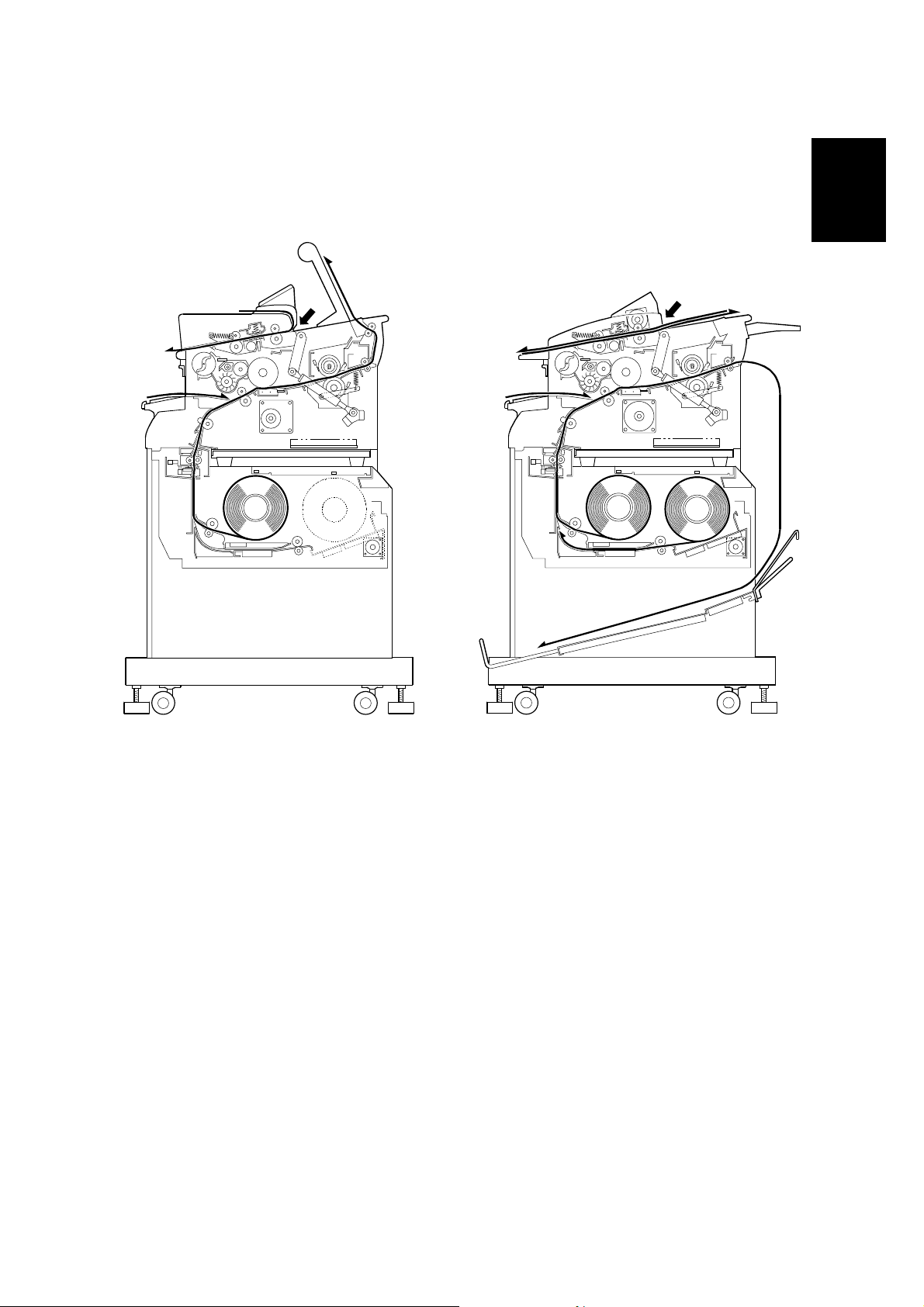
11 May, 2001 PAPER PATH
1.2 PAPER PATH
- B047 copier -
- B048 copier -
Overall
Information
A
B
C
B047V102.WMF
E
D
E
A
B
D
C
B048V102.WMF
A: Original Path
B: Manual Feed Path
C: Roll Feeder Path
D: Paper Exit
E: Original Path: Rear Feeder
There are two versions of this machine. The B047 is the basic version. It can only
make one copy at a time. The B048 is the multi-print version. It can make multiple
copies of an original (scanning and copying an original multiple times).
Both versions can be equipped with either a single or a double paper roll.
1-3
Page 14

MECHANICAL COMPONENTS 11 May, 2001
1.4 MECHANICAL COMPONENTS
14
13
19
18
17
16
15
20 21 22 1 2
3
4
5
6
7
8
9
10
11
1. 1st Original Feed Roller
2. 1st Press Rollers
3. Copy Tray
4. Exit Rollers
5. Fusing Exit Rollers
6. Hot Roller
7. Pressure Roller
8. Gas Spring
9. OPC Drum
10. T/S Corona Unit
11. Main Drive Unit
12
B047V101.WMF
12. Roll Feed Unit (1 roll or 2 rolls)
13. Roll Paper
14. Paper Registration Rollers
15. Manual Feed Table
16. Development Unit
17. Toner Cartridge
18. 2nd Original Feed Roller
19. Original Table
20. 2nd Original Press Roller
21. Exposure Lamp
22. Fiber Optic Array
1-4
Page 15

11 May, 2001 MECHANICAL COMPONENTS
27
28 29
26
25
23
Overall
Information
23. Original Guide
24. Optional Copy Tray
25. Original Entrance Roller
26. Original Entrance Press Roller
24
B048V101.WMF
27. Original Roller Feed Motor
28. Original Rear Press Roller
29. Original Rear Roller
1-5
Page 16

ELECTRICAL COMPONENTS 11 May, 2001
1.6 ELECTRICAL COMPONENTS
Refer to the electrical component layout on the reverse side of the Point to Point
index (Water proof paper).
Name Function Index. No.
Motors
Main Drives all mechanical components except the fans
(DC Motor).
Exhaust Fan Removes the ozone built up around the drum
section to the ozone filter (DC Motor).
Original Feed
(B048 only)
Magnetic Clutches
Registration Drives the registration rollers. 30
Toner Supply Turns on to supply toner to the development unit. 31
Solenoids
Pick-off Pawl Moves the pick-off pawls against the drum. 6
Drives the original feed motor (DC Motor).
32
5
45
Switches
Main Supplies power to the copier. 17
Original & Paper
Feed Safety
Fusing Exit Safety Cuts AC power when the fusing exit unit is opened. 12
Used Toner Cover “Door Open” is displayed on the operation panel
Sensors
Door Open Indicates “Door Open” on the operation panel and
Toner Density Detects the density of toner in the developer. 26
Original Registration Activates when the leading edge of the original
Light Measures the intensity of the exposure lamp’s
Entrance Feed Activates when copy paper is inserted (jam
Registration
Exit Detects jams through the fusing exit unit. 7
Original Entrance
(B048 only)
Original Rear
(B048 only)
Exit Cover Open Indicates “Door Open” in the operation panel and
Toner Overflow Detects whether the used toner tank is full or not. 46
Cuts AC power when the original or paper feed unit
are opened.
when the used toner cover is open.
prevents operation.
passes the front of the exposure glass.
output.
detector).
Activates when copy paper arrives at the
registration rollers (jam detector).
Measures the original length and detects jams. 43
Detects original jams. 44
prevents operation.
18
48
29
4
27
24
25
47
1-6
Page 17

11 May, 2001 ELECTRICAL COMPONENTS
Name Function Index. No.
Printed Circuit Boards
Main Controls all copier functions both directly and
through other PCBs.
22
PSU Converts t h e voltag e from AC to DC voltage. 21
AC Drive Provides AC power to the fusing lamp and PSU. 15
FL Regulator Stabilizes power to the exposure lamp. 23
Operation Panel Controls the operation panel display. 10
Lamps
Exposure Provides light to reflect the original’s image onto
the drum (fluorescent lamp).
2
Fusing Provides heat to the fusing unit. 3
Pre-Transfer (PTL) Reduces the charge on the drum surface prior to
image transfer.
Quenching (QL) Neutralizes any charge remaining on the drum
surface after cleaning.
20
1
Power Packs
Charge/Bias/
Grid Power Pack
Transfer/Separation Provides high voltage power for the transfer corona
Provides high voltage power for the charge corona,
charge grid, and development bias.
and separation.
19
16
Overall
Information
Thermistors
Hot Roller Monitors the hot roller’s surface temperature. 8
Pressure Roller Monitors the pressure roller’s surface temperature. 11
Thermofuses
Fusing Protects the fusing unit against overheating. 9
Heaters
Anti-condensation Keeps m oistur e from forming inside the copier
(option).
13
Others
Total Counter Keeps track of the total length of copies made
(Europe) or the total copies made (U.S.A.).
Circuit Breaker
Guards against voltage surges in the input power.
(Europe, Asia)/
28
14
Fuse (U.S.A.)
1-7
Page 18
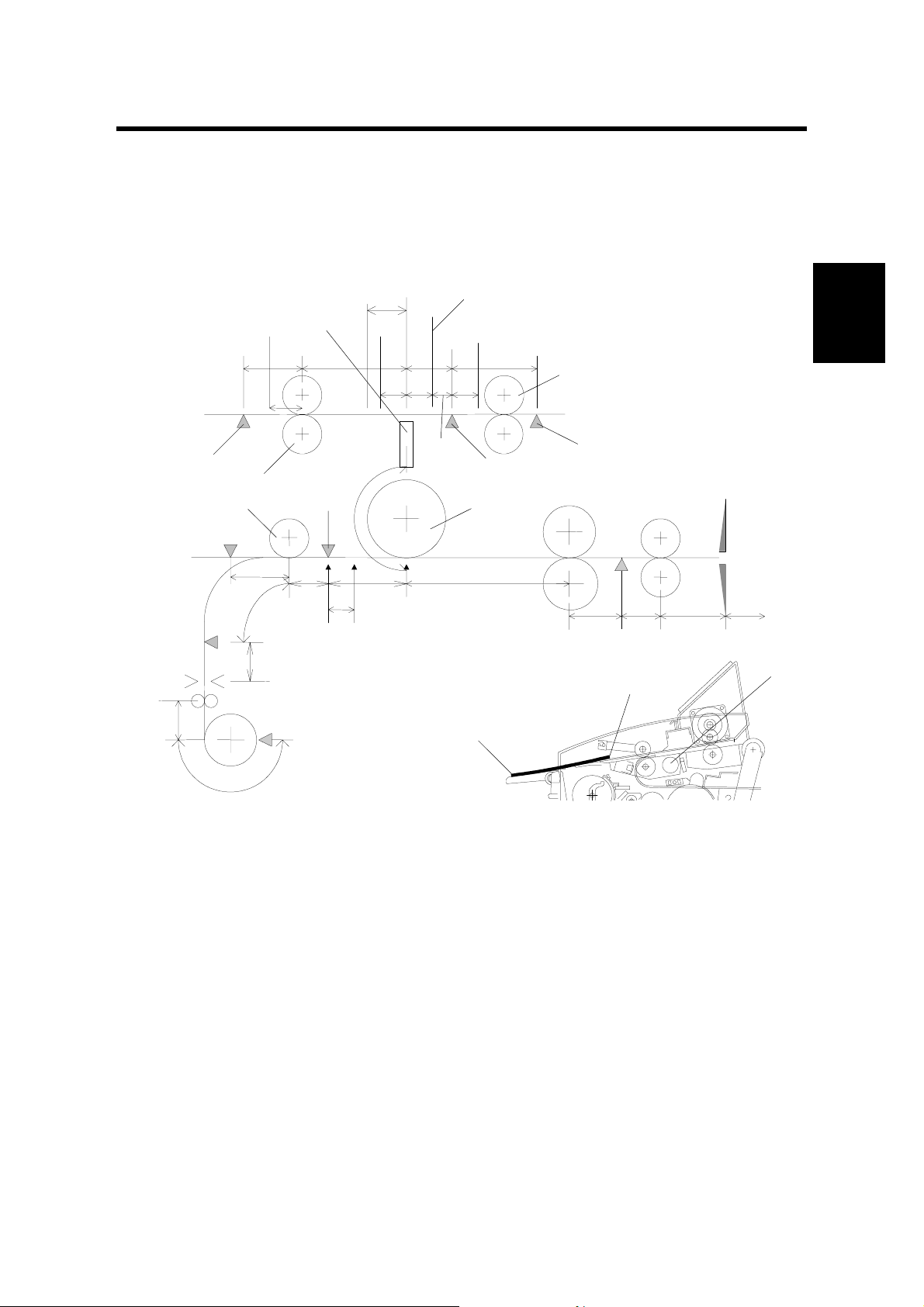
11 May, 2001 EXPOSURE
2. DETAILED SECTION DESCRIPTIONS
2.3 EXPOSURE
2.3.2 PAPER AND ORIGINAL FEED (B048 ONLY)
[E]
[C]
[G]
[D]
[L]
26 mm
[F]
[H]
10 mm
[I]
J: Original Rear Roller
K: Original Rear Sensor
L: Fiber Optics Array
[B]
[J]
[K]
[A]
Detailed
Descriptions
[M]
B047D500.WMF
B047D501.WMF
NOTE: For clarity’s sake, the following description will ref er to the paper’s edges
as edge [A] (furthest edge from the operator) and edge [B] (closest to the
operator).
Original Positioning
In the B048 copier, edge [A] of the original is placed onto the original table. This
activates the original entrance sensor [C].
The main motor turns the original entrance rollers [D]. The quenching lamp,
development bias and PTL also turn on.
For proper feeding (especially for a thin original), the original entrance rollers rotate
backwards (feeding towards the operator) for 300 ms. This ensures that the original
is gripped firmly by both of the original entrance rollers [D], feeding it evenly.
2-1
Page 19

EXPOSURE 11 May, 2001
4 seconds after the sensor is activated, the original feed motor starts rotating. This
delay gives the user time to align edge [A] against the original entrance rollers [D].
This helps prevent skew.
The original is fed through the machine to the scanning start position [E]. This
machine scans the original backwards, starting with edge [B] and scanning towards
edge [A]. The original is now ready to scan.
Scanning
The original is scanned, moving back towards the operator.
When edge [ A] activates the original registration sensor [F], the roll paper feed
motor turns on. Copy paper begins to feed, and the registration clutch is activated.
When edge [B] reaches the original feed start posi tion [E] (26 mm ahead of the
original registration sensor [F]), the original feed motor stops to wait for the copy
paper.
In the copy section, the registration clutch turns off once the copy paper’s leading
edge is 10 mm past the registration sensor [H]. The voltage is now applied to the
charge coro na.
The original feed motor begins rotating towards the operator again at 60 mm/s, and
the original is delivered to the exposure glass. Light from the exposure lamp [M] is
reflected off the paper to the fiber optics array [L].
Once the original’s edge [B] passes the original entrance sensor, the registration
clutch and roll paper feed motor turn on agai n. The pap er feed res ume s and the
copy paper is transported to the drum [I].
To measure the original length for cutting, the copier’s CPU measures the time
from when the original registration sensor detects edge [A] until the original
entrance sensor detects edge [B].
The copy paper length is measured by counting the number of steps as the roll
paper feed motor (a stepper motor) turns. Just before the paper is cut, the feed
motor speed doubles. This creates a buckle at the trailing edge of the copy paper.
The feed motor then stops as the cutter unit cuts the paper. Copying, however,
continues. The buckle provides the necessary slack while cutting.
When making duplicate copies, the original feed motor pauses, then changes
directions again, and the original is fed back to the scanning position 200 mm/s.
Once previous paper exits out of the roll feeder, the roll paper feed starts as well,
and the process repeats.
After all copies are made, the original is delivered to the original table. If original
hold mode is enabled (SP16), the original will stop with edge [A] caught by the
original entrance rollers. The original can be fed out by pressing the ! key. If
original hold mode is not enabled, the original feeds out completely, and is not
caught.
2-2
Page 20

11 May, 2001 EXPOSURE
Start Key Enable
When the start key enabled (SP34) is set, the start key acts as a starting trigger. In
this mode, when the original activates the original registration sensor, edge [B] is
delivered to the original registration sensor position. Everything pauses until the
user presses the start key. Original feed and paper feed then resume.
Detailed
Descriptions
2-3
Page 21

DEVELOPMENT 11 May, 2001
2.4 DEVELOPMENT
2.4.4 TONER DENSITY CONTROL
The toner supply amount ratio is determined by the following conditions.
N
L
H
TS
Level
0
1
2
3
4
5
0
1
2
3
4
5
0
1
2
3
4
5
201 ~ 250
sheets
(120 ~ 150 m)
<
2.25 ≤ V
2.70
<
2.70 ≤ V
3.15
<
3.15 ≤ V
3.60
<
3.60 ≤ V
3.90
3.90 ≤ V
<
3.25 ≤ V
3.50
<
3.50 ≤ V
3.80
<
3.80 ≤ V
4.00
<
4.00 ≤ V
4.35
4.35 ≤ V
<
2.00 ≤ V
2.40
<
2.40 ≤ V
2.80
<
2.80 ≤ V
3.20
<
3.20 ≤ V
3.60
3.60 ≤ V
TS
TS
TS
TS
TS
TS
TS
TS
TS
TS
TS
TS
<
<
<
<
TS
<
<
<
<
TS
<
<
<
<
TS
(30 ~ 60 m)
<
3.50 ≤ V
<
3.80 ≤ V
<
4.10 ≤ V
<
4.20 ≤ V
<
4.30 ≤ V
<
4.33 ≤ V
<
4.36 ≤ V
<
4.40 ≤ V
<
3.00 ≤ V
<
3.50 ≤ V
<
4.00 ≤ V
<
4.20 ≤ V
51 ~ 100
sheets
3.80
4.10
4.20
4.35
4.35 ≤ V
4.33
4.36
4.40
4.43
4.43 ≤ V
3.50
4.00
4.20
4.30
4.30 ≤ V
TS
TS
TS
TS
TS
TS
TS
TS
TS
TS
TS
TS
TS
TS
TS
0 ~ 50 sheets
(~ 30 m)
TS
V
< 4.00 VTS < 3.50 VTS < 3.00 VTS < 2.50 VTS < 2.25 VTS < 2.00
4.00 ≤ V
TS
4.10
4.10 ≤ V
TS
4.20
4.20 ≤ V
TS
4.30
4.30 ≤ V
TS
4.40
4.40 ≤ V
TS
V
4.35 ≤ V
TS
< 4.35 VTS < 4.30 VTS < 4.25 VTS < 3.75 VTS < 3.25 VTS < 2.75
TS
4.38
4.38 ≤ V
TS
4.40
4.40 ≤ V
TS
4.42
4.42 ≤ V
TS
4.45
4.45 ≤ V
TS
V
4.00 ≤ V
TS
< 4.00 VTS < 3.00 VTS < 2.50 VTS < 2.25 VTS < 2.00 VTS < 1.80
TS
4.10
4.10 ≤ V
TS
4.20
4.20 ≤ V
TS
4.30
4.30 ≤ V
TS
4.40
4.40 ≤ V
TS
(60 ~ 90 m)
<
3.00 ≤ V
<
3.50 ≤ V
<
4.00 ≤ V
<
4.20 ≤ V
<
4.25 ≤ V
<
4.30 ≤ V
<
4.33 ≤ V
<
4.36 ≤ V
<
2.50 ≤ V
<
3.00 ≤ V
<
3.50 ≤ V
<
4.00 ≤ V
101 ~ 150
sheets
TS
3.50
TS
4.00
TS
4.20
TS
4.30
4.30 ≤ V
TS
4.30
TS
4.33
TS
4.36
TS
4.40
4.40 ≤ V
TS
3.00
TS
3.50
TS
4.00
TS
4.25
4.25 ≤ V
(90 ~ 120 m)
<
2.50 ≤ V
<
3.00 ≤ V
<
3.50 ≤ V
<
4.00 ≤ V
TS
<
3.75 ≤ V
<
4.00 ≤ V
<
4.10 ≤ V
<
4.20 ≤ V
TS
<
2.25 ≤ V
<
2.70 ≤ V
<
3.15 ≤ V
<
3.60 ≤ V
TS
151 ~ 200
sheets
TS
3.00
TS
3.50
TS
4.00
TS
4.25
4.25 ≤ V
TS
4.00
TS
4.10
TS
4.20
TS
4.38
4.38 ≤ V
TS
2.70
TS
3.15
TS
3.60
TS
3.90
3.90 ≤ V
TS
TS
TS
251 sheets ~
(150 m ~)
TS
2.00 ≤ V
<
2.40
TS
2.40 ≤ V
<
2.80
TS
2.80 ≤ V
<
3.20
TS
3.20 ≤ V
<
3.60
TS
TS
<
3.60 ≤ V
2.75 ≤ V
3.20
TS
3.20 ≤ V
<
3.60
TS
3.60 ≤ V
<
3.90
TS
3.90 ≤ V
<
4.30
TS
TS
<
4.30 ≤ V
1.80 ≤ V
2.00
TS
2.00 ≤ V
<
2.50
TS
2.50 ≤ V
<
3.00
TS
3.00 ≤ V
<
3.50
3.50 ≤ V
TS
TS Level (Toner Supply Ratio)
0: No supply 1: 7.5% 2: 7.5% 3: 7.5% 4: 15% 5: 100%
Toner density control table has been changed for B047/B048 copiers.
2-4
Page 22

11 May, 2001 DEVELOPMENT
Recovery from Toner End Condition
After replacing the toner cartridge (opening and closing the original feed unit), the
main motor rotates the development unit for 60 seconds. During the first 30
seconds, toner is supplied at 100% of the supply amount until TS level reaches 3.
The main motor continues to rotate the development unit for another 30 seconds.
Then copies can be made.
If the TS level does not reach 3, the CPU stops the machine and displays the toner
end condition. This prevents the operator from resetting the toner end condition by
simply opening and closing original feed unit.
Detailed
Descriptions
2-5
Page 23
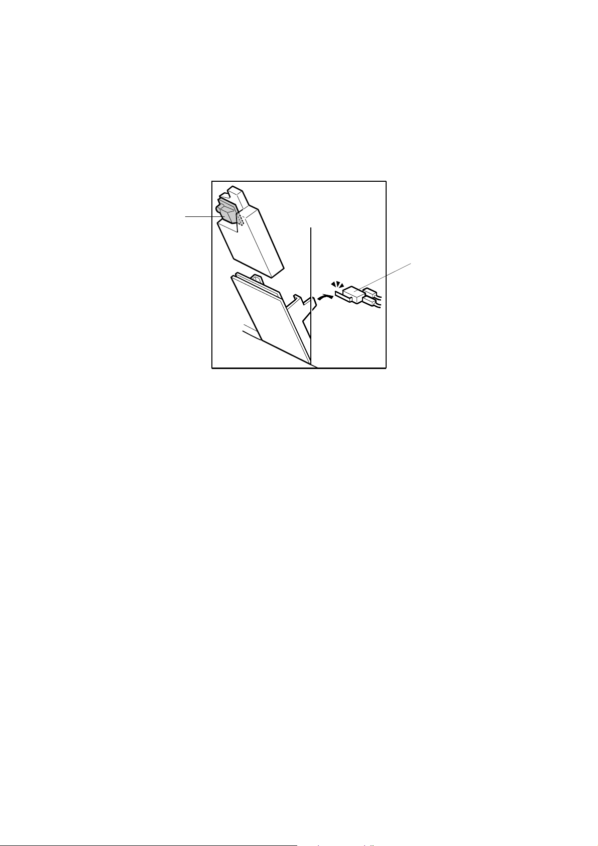
CLEANING 11 May, 2001
2.6 CLEANING
2.6.2 USED TONER COLLECTION
[A]
[B]
B047D101.WMF
B047/B048 copiers have a used toner overflow sensor [A] and a used toner cover
switch [B].
When the used toner overflow sensor detects that the used toner tank is full, the
overflow indicator begins blinking on the operation panel. 30 more meters (A1/D
size: 50 copies, SP51) can be copied. After that, the used toner overflow indicator
stays ON, and the machine will not operate.
The used toner cover switch detects when the used toner cover is open. “Door
open” is displayed on the operation panel, and the start key is disabled.
2-6
Page 24
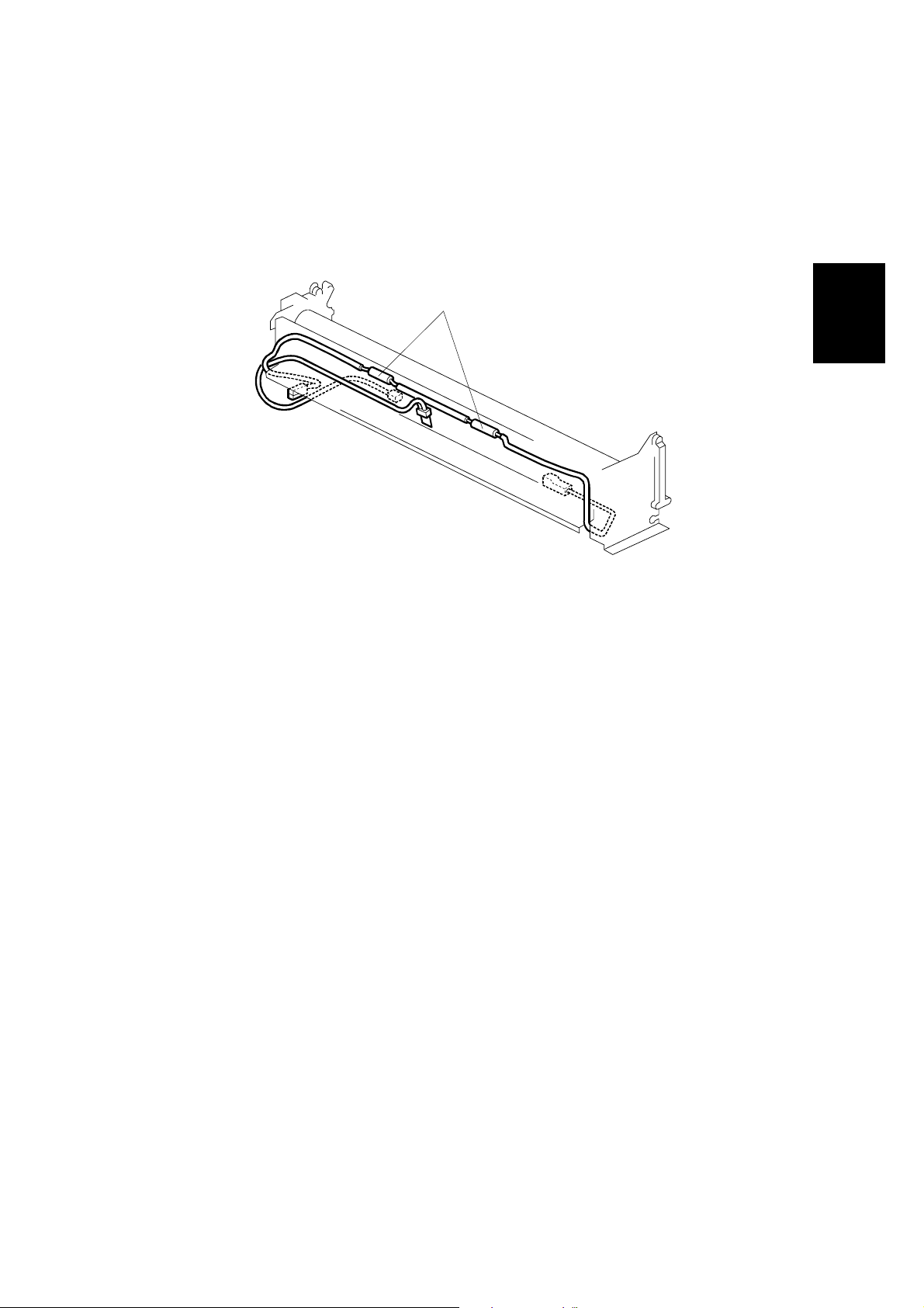
11 May, 2001 FUSING AND PAPER EXIT
2.8 FUSING AND PAPER EXIT
2.8.1 OVERVIEW
[A]
Detailed
Descriptions
B047D102.WMF
Two thermofuses [A] (184°C, 192°C) keep the fusing unit from overheati ng .
Two thin-film thermistors measure the hot roller and pressure roller’s temperature.
The hot roller is a thin-shell, Teflon coated roller. The thinne r roller allows a much-
shorter warm-up time. However, extra care should be taken while working around
the hot roller. It is very easy to damage.
Like the A163/A251/A252 copiers, if the fusing temperature is lower than 60°C
when the main switch is turned on, the machine assumes that it has not been used
recently, and the main motor must rotate to generate the necessary triboelectric
charge on the toner and developer.
In the A163/A251/A252 copiers, the main motor begins rotating immediately.
However, the B047/B048 copiers have a thin shell hot roller and a contact
thermistor. When cold, the thermistor is hard and might damage the roller. The
machine waits until the hot roller temperature reaches 80°C. At that temperature
the thermistor softens and the hot roller can rotate safely.
Except for the differences listed above, the B047/B048 copiers are identical to the
A251 and A252 copiers. Please refer to A163/A251/A252 copier service manual for
additional details.
2-7
Page 25
FUSING AND PAPER EXIT 11 May, 2001
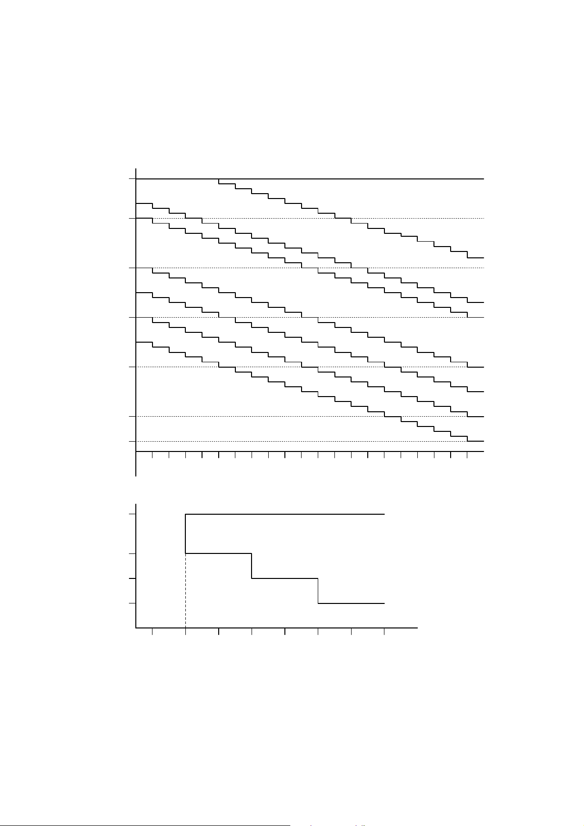
2.8.3 TEMPERATURE CONTROL
Hot Roller Temperature Control
Hot Roller Temp. (°C)
198
190
180
170
160
150
142
Mode 8
Mode 7
Mode 6
Mode 5
Mode 4
Mode 3
Mode 2
Mode 1
~60
63 66 69 72 75 78 81 84 87 90 93 96 99 102105108111 114 117 120~
Pressure Roller Temp. (°C)
198
190
185
180
110 115 120 125 130 135 140 145
Lower Limit
Mode 8
Operating Temperature
Lower Limit
B047D001.WMF
The relationship between the hot roller and pressure roller temperatures has been
changed due to the thin-shell, Teflon coated roller.
2-8
Page 26
11 May, 2001 ENERGY STAR COMPLIANT MACHINES (ALL THE DESTINATION)
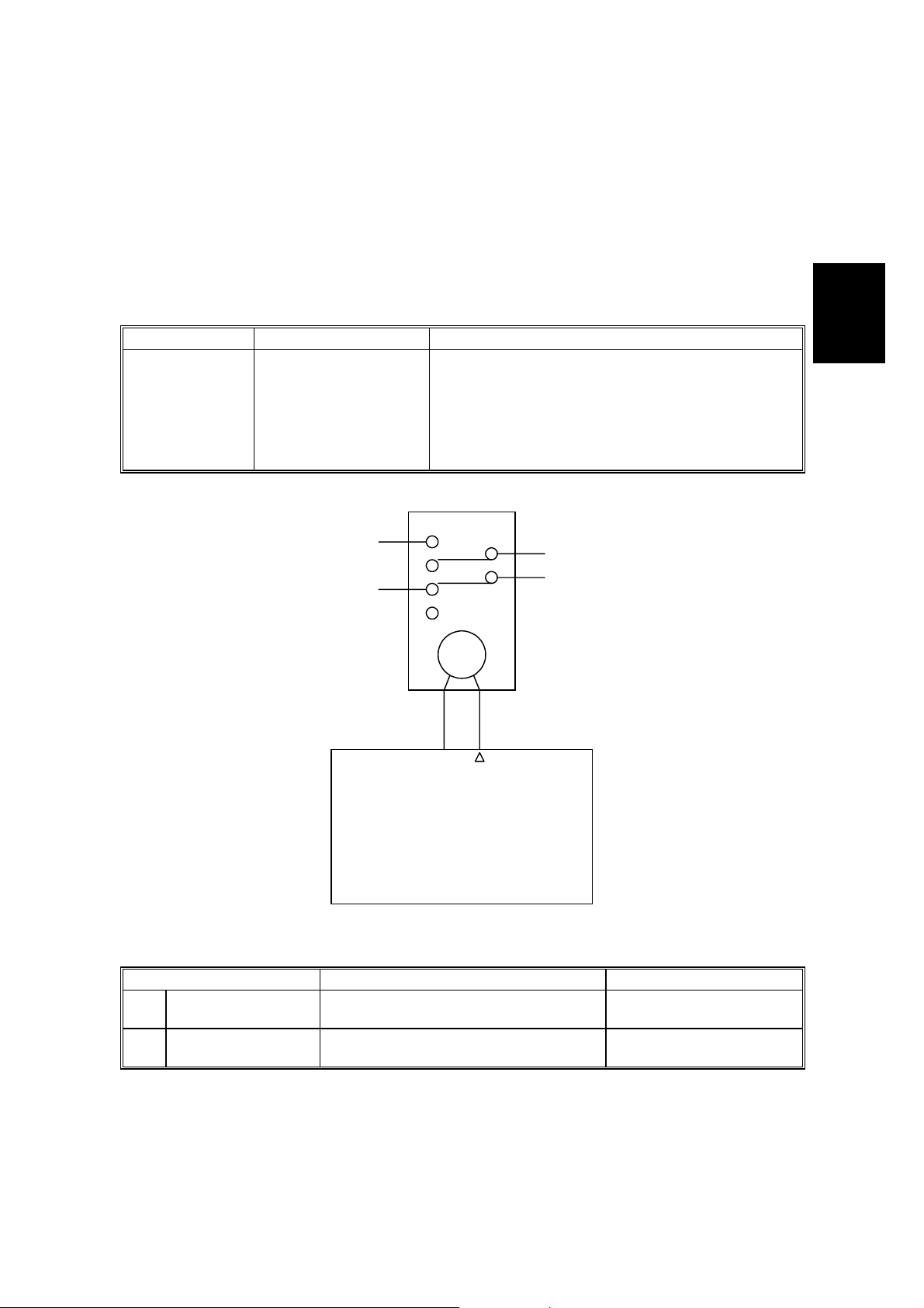
2.10 ENERGY STAR COMPLIANT MACHINES (ALL THE DESTINATION)
In conjunction with the modification for the Energy Star compliance, field
technicians need to understand the new operation modes, and must be able to
configure the machine for the customer’s specific environment/requirements. This
section lists all the differences between the Energy Star compliant machines and
the previous models.
Mode Non-Energy Star Energy Star
Starts timing once the last copy job is
complete. When the specified time has
Auto Off Mode Not available
passed, the copier turns off.
The time can be adjusted from 1 to 240
minutes.
Default: 30 minutes
RA
CN102
-A3
-B13
24]
[24]
!
AA
V
Detailed
Descriptions
Power Relay [
B047D002.WMF
Mode No. Function Data
Auto Shut-off Time
*15
Setting
AOF Auto off enable. 0: Disable
*33
Determines the auto shut-off time.
2-9
1 ← 30 → 240
1: Enable
Page 27

11 May, 2001 INSTALLATION REQUIREMENTS
3. INSTALLATION
3.1 INSTALLATION REQUIREMENTS
3.1.1 ENVIRONMENT
1. Temperature Range:
2. Humidity Range: 20% to 80% RH
3. Ambient Illumination: Less than 1,500 lux (do not expose to direct
4. Ventilation: Room air should turn over at least 3 times per hour.
5. Ambient Dust: Less than 0.10 mg/m3 (2.7 x 10⁻⁶ oz/yd3)
6. If the location is air-conditioned or heated, place the machine as follows:
a) Where it will not be subjected to sudden temperature changes from low to
high, or vice versa.
b) Where it will not be directly exposed to cool air from an air conditioner in
the summer.
c) Where it will not be directly expos ed to heat.
7. Avoid exposure to corrosive gases.
8. Avoid installing anywhere higher than 2,000 m (6,500 ft) above sea level.
9. Place the machine on a strong and level base.
10. Avoid any area where the machine may be subjected to frequent, strong
vibration.
15°C to 30°C (50°F to 86°F)
sunlight).
Installation
3-1
Page 28
INSTALLATION REQUIREMENTS 11 May, 2001
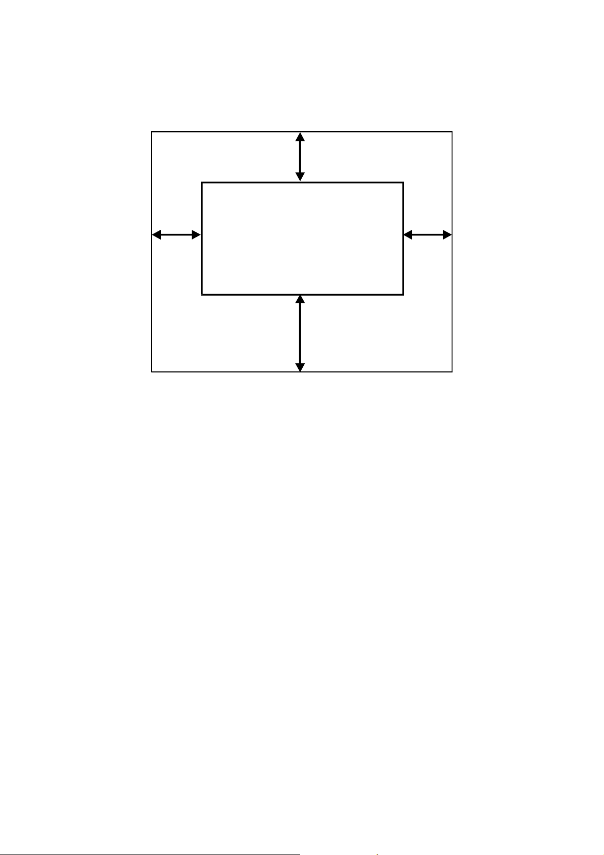
3.1.2 MINIMUM SPACE REQUIREMENTS
Back 600 mm
Left
600 mm
1. Front: 1,000 mm (39 in)
2. Back: 600 mm (24 in)
3. Right: 600 mm (24 in)
4. Left: 600 mm (24 in)
3.1.3 MACHINE LEVEL
Right
600 mm
Front 1,000 mm
B047I505.WMF
1. Front to back: Within 5 mm (0.2") of level
2. Right to left: Within 5 mm (0.2") of level
Make sure that the machine is level using a carpente r’s level.
3-2
Page 29

11 May, 2001 INSTALLATION REQUIREMENTS
3.1.4 POWER SOURCE
Important:
The machine must be installed in a building/facility equipped with a protective
device such as a circuit breaker, as the machine relies on such devices for
protection against over-current and short circuits.
1. Input Voltage Level: 120 V, 60 Hz
More than 12 A (for U.S.A. version)
220 ~ 240 V, 50/60 Hz
More than 7 A (f or European version)
2. Permissible Voltage
±10%
Fluctuation:
3. Do not set anything on the power cord.
NOTE: 1) Make sure the plug is firmly inserted in the outlet.
2) Avoid multi-wiring.
Installation
3-3
Page 30

INSTALLATION PROCEDURE 11 May, 2001
3.2 INSTALLATION PROCEDURE
3.2.1 COPIER
Accessory Check
Check the accessories and their quantities according to the following list:
- B048 copier -
Original Guides........................................................................ 6 pcs
Operating Instruction Holder.................................................... 1 pc
Operating Sheet ...................................................................... 1 pc
Caution Decal (-27 only).......................................................... 1 pc
Operating Instructions (-17 only).............................................. 1 pc
Original Guide Wire................................................................. 1 pc
- B047 copier -
Guide Wires............................................................................. 2 pcs
Copy Tray................................................................................ 1 pc
Copy Guide.............................................................................. 1 pc
Operating Instruction Holder.................................................... 1 pc
Operating Sheet ...................................................................... 1 pc
Caution Decal (-27 only).......................................................... 1 pc
Operating Instructions (-17 only).............................................. 1 pc
3-4
Page 31

11 May, 2001 INSTALLATION PROCEDURE
[D]
[A]
[B]
[C]
B047I024.WMF
Preparation for the B047 copier on the roll feeder.
When B047 copier is placed on the roll feeder, first remo ve the lower front cover [A]
and the manual feed table [B] for installatio n.
1. Remove the lower front cover [A] (2 screws), reinforcement plate [C] (1 screw),
bracket [D] (4 screws) (which is hung by the harness), and the manual feed
table [B].
2. Put back the bracket and reinforcement plate.
Installation
3-5
Page 32

INSTALLATION PROCEDURE 11 May, 2001
- B047 model -
[E]
[B]
- B048 model -
[F]
[F]
[C]
B047I500.WMF
[A]
[F]
[B]
[E]
[F]
[D]
[A]
B048I502.WMF
NOTE: The installation procedures are not shipped with the copier, always bring
this manual with you.
!
CAUTION
1. Unplug the power cord before performing the following procedures.
2. Before starting the installation, make sure the machine is level.
3. The copier is very heavy (85 kg, 187 lbs). To avoid serious injury, make
sure that you have a sufficient number of people to assist you. It takes
at least two people to lift the copier safely.
4. Please be careful not to get your hand caught under the copier as you
place the copier onto the table or roll feeder.
NOTE: Keep the shipping retainers after installing the machine. They will be
reused if the machine is moved to another location in the future.
1. For either the table or the roll feeder, lower the feet [A] (table: 2 feet, roll feeder:
4 feet) so that it does not move while the copier is being installed.
2. Place the copier [B] on the table [C] or roll feeder [D] (Place the copier feet [E]
into the table holes [F]).
!
WARNING
The copier is not attached to the table. Pushing the copier too hard may
cause it to fall. While moving the copier, always push the table.
3-6
Page 33

11 May, 2001 INSTALLATION PROCEDURE
B047I001.WMF
[A]
[J]
[C]
[D]
[A]
[B]
[L]
[K]
[J]
[F]
[I]
[D]
[E]
[L]
B047I103.WMF
Installation
[G]
B047I104.WMF
[H]
B047I105.WMF
3. Remove all the tape strips [A] as shown.
4. Open the original feed unit [B].
5. Remove the cushion [C] and close the original feed unit.
6. Release the lock levers [D] and open the paper path section [E].
7. Remove the right upper cover [F] (2 screws).
8. Remove the drum protection sheet [G] and remove the screw [H]. This applies
cleaning blade pressure to the drum.
NOTE: Be sure to remove the protective sheet before removing the pressure
screw. Otherwise, the cleaning blade will clamp the sheet to the drum,
and the drum may be damaged.
9. Open the fusing exit section [I]. Remove the two strips of shipping tape [J] and
the protection sheet [K].
10. Remove two strips of shipping tape [L]. Close the paper path section and fusing
exit section.
3-7
Page 34

INSTALLATION PROCEDURE 11 May, 2001
[A]
[E]
[C]
[B]
B047I503.WMF
[D]
B047I504.WMF
11. Open the original feed unit [A], manual feed table [B], and toner supply cover
[C]. Remove the sheet [D] covering the developer entrance. Pour 1 kg of the
developer [E] into the development unit evenly across its width as shown.
NOTE: Close the paper path section before opening the toner supply cover. If
the paper path section is open, the toner supply cover could fall off.
12. Plug in the power supply cord and turn on the main switch.
3-8
Page 35
11 May, 2001 INSTALLATION PROCEDURE
[A]
[C]
Installation
[B][D]
[E]
B435I508.WMF
NOTE: If the fusing temperature is lower than 60°C when the main switch is turned
on, the main motor must rotate to generate a triboelectric charge on the
developer and toner. However, to prevent damage to the hot roller, the
main motor will wait until the hot roller’s temperature reaches 80°C before
rotating. This may take a few minutes.
In this case, it is not necessary to use the SP mode to load the developer.
Skip steps 13 to 16. After the developer is loaded from the development
entrance, turn off the main switch to stop the main motor. Pour in the
second 1 kg of developer.
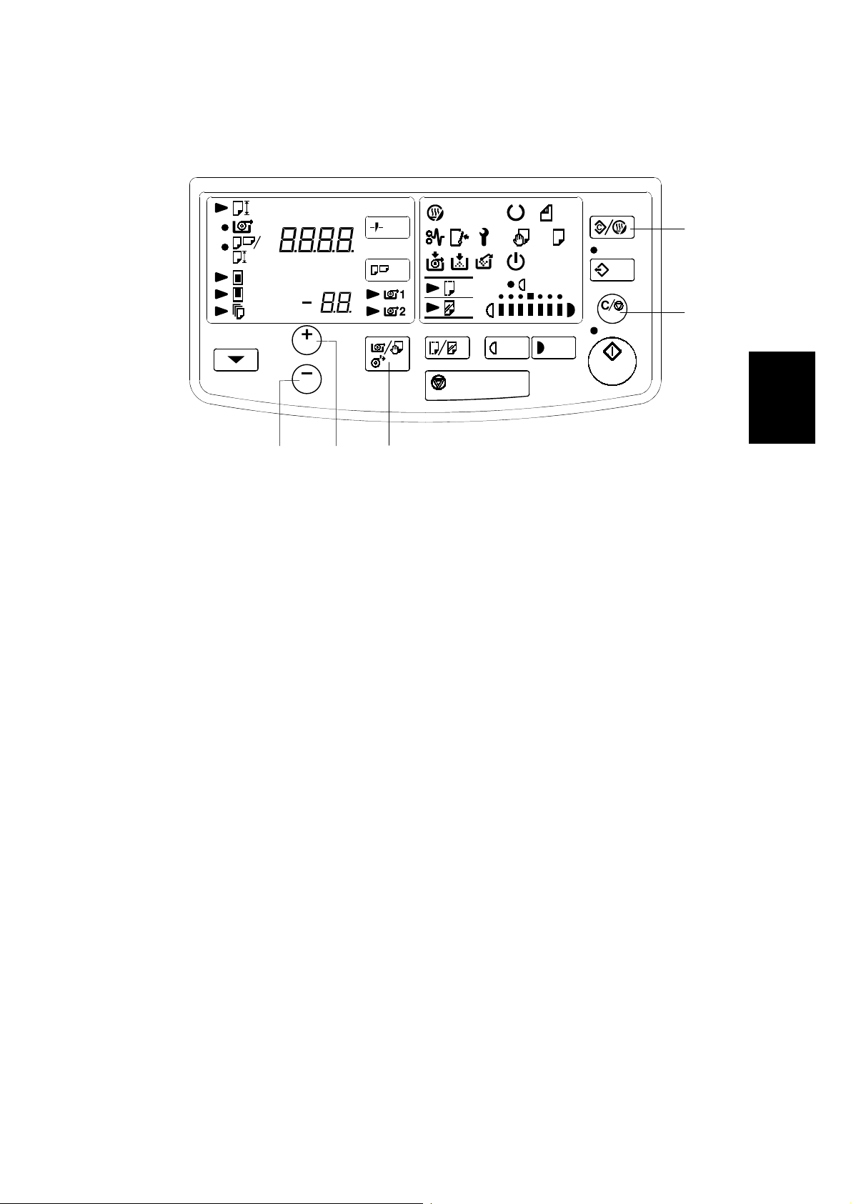
13. To begin main motor rotation, enter the SP INPUT/OUTPUT mode by pressing
the following keys on the operation panel:
Clear Mode key [A]
+ key [B]
+ key [B]
Clear/Stop key [C]
Clear/Stop key [C] again and hold for at least 3 seconds.
14. After 3 seconds, the wrench and toner end indicators will blink (SP
INPUT/OUTPUT mode).
15. Use the + and – keys [D] to select 23, then press the RF Select key [E]. The
main motor will begin rotating.
16. Press the RF Select key to stop the main motor once the developer is loaded
from the development entrance. Pour in the second 1 kg of developer into the
development unit evenly across its width (Total: 2 kg). Press the Clear
Modes/Stand by key 3 times to leave the SP mode.
3-9
Page 36

INSTALLATION PROCEDURE 11 May, 2001
[A]
[D]
[B][C][E]
[F]
B435I508.WMF
17. To enter the SP mode, press the following keys on the operation panel:
Clear key [A]
+ key [B]
– key [C]
Clear/Stop key [D]
Clear/Stop key [D] again and hold for at least 3 seconds.
18. After 3 seconds. The roll paper end and call se rvice in dicators will blink (SP
mode).
19. Using the + and – keys, select 36. Enter “1” by pressing the following keys.
Function Select key [E]
+ key
RF Select key [F]
This begins the developer initialization. Initialization takes about five minutes,
after which the copier will automatically retu rn to the normal operation mode.
3-10
Page 37

11 May, 2001 INSTALLATION PROCEDURE
[A]
[B]
[C]
B047I507.WMF
20. Install the toner cartridge [A] as shown.
1) Shake the cartridge 5 to 10 times and insert it into the toner hopper.
2) Peel off the green tape [B] from right to left to expose the clear tape and
toner supply holes.
3) Rotate the knob [C] of the cartridge clockwise until it stops.
Installation
3-11
Page 38

INSTALLATION PROCEDURE 11 May, 2001
[B]
[A]
B047I506.WMF
B048 copier only (step 21)
[C]
[E]
[D]
B047I509.WMF
21. Install the original guides [A] and original guide wire [B].
B047 copier only (step 22 and 23)
22. Attach the guide wires [C] to the copy tray [D].
23. Install the copy tray [D] and copy guide [E].
Both copiers (step 24 and 25)
24. Reinstall all the covers.
25. Check the copy quality and copier operation.
26. Install the optional roll feeder. (Refer to the Roll Feeder 1 and 2 Installation
procedures)
NOTE: While the roll feeder is optional for the B047, it is required for the B048.
You must install a roll feeder for the B048 to function properly.
3-12
Page 39

11 May, 2001 INSTALLATION PROCEDURE
3.2.2 TABLE (B439)
Accessory Check
Check the accessories and their quantities according to the following list:
Top Plate ................................................................................ 1
Left Side Plate ........................................................................ 1
Right Side Plate ...................................................................... 1
Middle Plate ............................................................................ 1
Rear Cover ............................................................................. 1
Screws with Spring Washers – M4x8 .....................................14
Installation
3-13
Page 40

INSTALLATION PROCEDURE 11 May, 2001
[C]
[B]
[F]
[A]
B439I500.WMF
[A]
[E]
[B]
[D]
B439I551.WMF
1. Loosely install the top plate [A], left [B], and right side plate [C] (6 screws).
2. Turn the table up-side down. Be sure to ro tate it as shown in the illustration.
[C]
3. Install the middle plate [D] and rear cover [E] (4 screws each).
4. Tighten all the screws until the spring washers [F] are completely flat.
5. Turn the table right-side up.
3-14
Page 41

11 May, 2001 INSTALLATION PROCEDURE
3.2.3 COPY TRAY (B440)
Accessory Check
Check the accessories and their quantities against the following list:
Copy Tray Stay........................................................................ 1
Copy Tray Support................................................................... 1
Copy Tray Guides.................................................................... 2
Copy Tray Sheets (with rubber pads)...................................... 3
Rear Copy Trays...................................................................... 3
Copy Tray Stoppers................................................................. 2
Stepped Screws – M4.............................................................. 2
Screws with Flat Washers – M4x6........................................... 6
Tray Sheet Guides................................................................... 3
Rear Copy Tray Sheets (no rubber pads)................................ 3
NOTE: The copy tray is an option for the B048 copier. When the copy tray is
installed on the copier, the roll feeder (B435/B436) is required.
Installation
3-15
Page 42

INSTALLATION PROCEDURE 11 May, 2001
[C]
[D]
[A]
B440I117.WMF
[E]
[F]
[G]
B440I121.WMF
[A]
1. Place the copy tray stay [A] under the copy tray as shown.
[B]
B440I118.WMF
[H]
B440I119.WMF
2. Adhere the copy tray sheets (the Mylar strips with rubber pads) [B] to the
table’s middle plate [C]. Make sure the center copy tray sheets is positioned
between the screw holes [D] on the copy tray as shown. The left and right copy
tray sheets should be positioned over the screw holes.
3. Lift the copy tray stay and install the two stepped screws [E] to the left and right
side plates [F, G]. After the screws are in place, hook the copy tray stay [A] on
the screws. Then secure it to the left and right side plates (2 screws for each:
M4x6 with flat washers).
NOTE: Be careful when installing the copy tray stay. Do not scratch the
surface of the table.
4. Install the copy tray support [H] (2 screws: M4x6 with flat washers).
3-16
Page 43

11 May, 2001 INSTALLATION PROCEDURE
[B]
[A]
B440I113.WMF
B440I115.WMF
0±2mm
0±2mm
[C]
10±5mm
0±5mm
[C]
B440I114.WMF
B440I116.WMF
10±5mm
Installation
5. Remove the rear cover [A] (2 screws).
6. Attach the rear copy tray sheets [B] and the tray sheet guides [C] to the rear
cover as shown.
7. Install the rear cover (2 screws).
3-17
Page 44

INSTALLATION PROCEDURE 11 May, 2001
[A]
[B]
B440I120.WMF
[C]
60±10mm
[D]
60±10mm
80±10mm
B440I123.WMF
8. Hook the rear copy trays [A] onto the copy tray stay [B].
9. Attach the copy tray stoppers [C] onto the bottom of the middle plate [D].
3-18
Page 45

11 May, 2001 INSTALLATION PROCEDURE
3.2.4 ROLL FEEDER1 AND 2 (B435/B436)
Accessory Check
Check the accessories and their quantities according to the following list:
Harness Covers....................................................................... 2 pcs
Ground Plates.......................................................................... 2 pcs
Roll Feeder Drive Board.......................................................... 1 pc
Left Joint Bracket..................................................................... 1 pc
Right Joint Bracket................................................................... 1 pc
Screws – M4x8 (Blue).............................................................. 4 pcs
Screws – M4x8 (Silver)............................................................10 pcs
Screws with Flat Washers – M4x10......................................... 2 pcs
Screw with a Spring Washer – M4x8....................................... 1 pc
Screws with Flat Washers – M3x6........................................... 2 pcs
Installation
Left Joint Cover........................................................................ 1 pc
Right Joint Cover..................................................................... 1 pc
Harness Clamp........................................................................ 2 pcs
Paper Holder
1 Roll................................................................................... 2 pcs
2 Roll................................................................................... 4 pcs
Guide Plate.............................................................................. 1 pc
Front Joint Cover..................................................................... 1 pc
Cutter Blade Caution Decal (-27 only)..................................... 1 pc
Joint Harness........................................................................... 1 pc
3-19
Page 46

INSTALLATION PROCEDURE 11 May, 2001
[D]
[A]
[B]
[C]
B047I024.WMF
Preparation for the B047 copier on the roll feeder.
When B047 copier is placed on the roll feeder, first remo ve the lower front cover [A]
and the manual feed table [B] for installatio n.
1. Remove the lower front cover [A] (2 screws), reinforcement plate [C] (1 screw),
bracket [D] (4 screws) (which is hung by the harness), and the manual feed
table [B].
2. Put back the bracket and reinforcement plate.
3-20
Page 47

11 May, 2001 INSTALLATION PROCEDURE
[C]
[E]
[D]
[E]
[B]
Installation
[A]
!
CAUTION
1. Unplug the main machine’s power cord before starting the following
procedure.
2. Before starting the installation, make sure the machine is level.
3. The copier is very heavy (85 kg, 187 lbs). To avoid serious injury, make
sure that you have a sufficient number of people to assist you. It takes
at least two people to lift the copier safely.
4. Please be careful not to get your hand caught under the copier as you
place the copier onto the roll feeder.
1. Lower the feet [A] (4 feet) so that the roll feeder [B] does not move while the
copier [C] is being installed.
!
CAUTION
Do not open the paper tray until the copier is placed on top of the roll
feeder. The paper tray drawer is very heavy. Without the copier weight to
hold it down, the roll feeder will fall over. The tray is shipped with a safety
latch holding the drawer shut.
B436I102.WMF
2. Place the copier on the roll feeder. Fit the copier feet [D] into the roll feeder
holes [E].
!
WARNING
The copier is not attached to the roll feeder. Pushing the copier too hard
may cause it to fall. While moving the copier, always push the roll feeder.
3-21
Page 48

INSTALLATION PROCEDURE 11 May, 2001
[B]
[A]
[C]
B435I507.WMF
[B]
[F]
[A]
[D]
B435I506.WMF
3. Release the lock lever [A] and open the copier paper path section [B].
[E]
4. Remove the copier’s left lower cover [C] (2 screws), lower right front cover [D]
(2 screws), lower right middle cover [E], and toner collection bottle [F] (1
connector).
3-22
Page 49

11 May, 2001 INSTALLATION PROCEDURE
[A]
[E]
[B]
B435I105.WMF
B435I101.WMF
Installation
[C]
B435I104.WMF
[D]
B435I127.WMF
5. Pull out the paper tray [A] and install the left [B] and right [C] joint brackets (2
screws each: blue).
6. Remove the paper tray stopper [D] (1 screw).
NOTE: After the copier has been placed on the roll feeder, the paper tray can
be pulled out and the paper tray stopper can be removed.
7. If necessary, adhere the appropriate language cutter blade caution decal [E]
over the English decal on the paper tray as shown (-27 only).
3-23
Page 50

INSTALLATION PROCEDURE 11 May, 2001
B435I106.WMF
[A]
[G]
[B]
[F]
[B]
[C]
B435I122.WMF
[D]
B435I124.WMF
[E]
[I]
B435I110.WMF
B435I108.WMF
[D]
8. Remove the roll feeder’s rear cover [A] (6 screws).
9. Remove the copier’s rear cover [B] (2 screws).
10. Remove the small caps [C] from the copier’s rear cover using cutting pliers.
11. Install the roll feeder drive board [D].
12. Connect the following harness connectors as shown.
DC harness [E] — Roll Feeder Drive board
Joint harness [F] — Roll Feeder Drive board
Joint harness [G] — Copier Main Control board (3 clamps)
AC harness [H] — AC Drive board [I]
[H]
3-24
Page 51

11 May, 2001 INSTALLATION PROCEDURE
[B]
[A]
[C]
[A]
B435I107.WMF
[C]
Installation
B435I109.WMF
B435I125.WMF
13. Install the grounding plates [A] (1 screw for each: M4x8).
14. Secure the grounding wire [B] (1 screw: M4x8 with a spring washer) to the
copier.
NOTE: To ensure proper grounding, tighten the ground wire’s screws until the
spring washer is completely flat.
15. Install the harness covers [C] (1 screw for each: M4x10 with flat washers).
NOTE: Fold the harness covers around the harness, then attach with a single
screw.
16. Reinstall the rear cover of the roll feeder (6 screws).
17. Clamp the power cord to the rear cover of the roll feeder (2 screws: M4x8).
18. Put back the copier’s rear cover.
3-25
Page 52

INSTALLATION PROCEDURE 11 May, 2001
[A]
B436I103.WMF
[B]
B435I111.WMF
[C, D]
B435I112.WMF
19. Hook the guide plate [A] on the copier and then secure it (2screws: M4x8).
20. Install the front joint cover [B] (2 screws: M3x6 with flat washers).
21. Reassemble the copier.
22. Install the left and right joint covers [C, D] (2 screws for each: M4x8 each).
3-26
Page 53

11 May, 2001 INSTALLATION PROCEDURE
[A]
[G]
[D]
[B][C][E]
Length
Temperature
NORMAL XX 42 XX 45
[F]
300
PRG.
NO.
1100
B435I508.WMF
PRG.
NO.
23. Plug in the power supply cord and turn on the main switch.
24. To enter the SP mode, press the following keys on the operation panel:
Clear Modes key [A]
+ key [B]
– key [C]
Clear/Stop key [D]
Clear/Stop key [D] again and hold it for at least 3 seconds.
25. After 3 seconds, the roll paper end and ca ll service indicators will blink (SP
mode).
26. Select 40 using the + and - keys. Enter “1” (B435: 1 roll) or “2” (B436: 2 rolls)
by pressing the following keys.
Function Select key [E]
+ key
RF Select key [F].
Installation
27. To set the paper cut length adjustments, input values into SP modes 42 and 45
as listed on the decal attached to the right side plate.
NOTE: 1) When the values for SP modes 42 and 45 are set, the paper cut
length adjustment values for vellum and film are automatically
entered (SP modes 43, 44, 46 and 47).
2) In the case of the 2 roll feeder, you must enter values for both the
1st and 2nd roll. The value for the 1st roll can only be entered when
the corresponding indicator [G] is blinking (same for 2nd roll). Use
the Function Select Key to switch between the two rolls.
28. Press the Clear Modes key 3 times to leave the SP mode.
29. Check the roll feeder operation.
3-27
Page 54

INSTALLATION PROCEDURE 11 May, 2001
3.2.5 ROLL CUTTING RAIL (B437)
The installation is identical to that of the A163 copier’s roll cutting rail (A570).
Please refer to the A163 service manual for details. The roll cutting rail and the roll
feeder cannot both be installed on the same machine at the same time.
3-28
Page 55

11 May, 2001 SERVICE TOOLS
4. SERVICE TABLES
4.3 SERVICE TOOLS
4.3.1 SERVICE PROGRAM MODE
Service Program Mode Table
1. A “*” before the mode number means that the mode can be accessed by
customers or sales representative.
2. In the data column, the default value is printed in bold letters.
The default settings for se veral items depend on the machine destination (ref er
to page 4-28.).
Mode No. Function Data
Fusing
Temperature 1
(Normal)
*1
Fusing
Temperature 2
*2
(High)
Fusing
Temperature 3
*3
(Low)
Copy Count
*4
Up/Down
Beeper On/Off Turns the beeper on and off. 0: On
*5
Paper Feed Out
Waiting Time
Setting
*6
Manual Feed Start
Time Setting
*7
Selects the fusing temperature for
plain paper.
Selects the fusing temperature for
translucent paper.
Selects the fusing temperature for
translucent film.
Select weather the user displa y panel
counts up or down.
Sets the copy time-out. Begins timing
when a sheet of copy paper has been
manually fed, or if the Roll Feed Select
key is pressed. If a copy is not made
within the specified time limit, the copy
paper is ejected.
Sets the manual feed delay. The timer
begins when the entrance sensor
detects the paper’s leading edge.
Once the specified time has passed,
the registration rollers start rotating.
0: Mode 1
1: Mode 2
2: Mode 3
3: Mode 4
4: Mode 5
5: Mode 6
6: Mode 7
0: Mode 5
1: Mode 6
2: Mode 7
3: Mode 8
0: Mode 2
1: Mode 3
2: Mode 4
3: Mode 5
0: Up
1: Down
1: Off
2: Turn the beeper off
when holding the button
down to rapidly change
the edge margin or
paper length.
0: 2 minutes
1: 1 minute
2: 3 minutes
3: 4 minutes
4: 5 minutes
0: 2 seconds
1: 0.7 second
2: 1 second
3: 3 seconds
4: 4 seconds
5: 5 seconds
Tables
Service
4-1
Page 56

SERVICE TOOLS 11 May, 2001
Mode No. Function Data
Leading Edge
Increase/Decrease
Speed Setting
*8
Auto Reset Time
Setting
*9
Auto Energy Saver
Mode
*10
Screen Message
Setting
*11
Leading Edge
Increase/Decrease
Adjustment
Preliminary Interval
*12
This sets the speed at which the
leading edge setting increases or
decreases.
When the customer holds down the +
or – key, there is a brief pause. After a
selected number of 0.25 second
intervals (See SP 12), the values begin
to change at the selected speed.
Sets the delay for the auto reset. After
finishing a copy job, the machine will
wait the specified amount of time. If no
other jobs are begun, it will then
automatically reset the copy settings to
its default values.
Enables and disables the auto energy
saver mode. If enabled, the machine
will automatically go into energy saver
mode after it auto resets.
Selects one of the options indicated on
the display in the energy saver mode.
When the user hold downs the + or –
key to change the leading edge
margin, print number or paper length,
there is a pause before the values
begin to change rapidly.
This paused is measured in 0.25
second intervals.
Changes every:
0: 0.1 second
1: 0.50 second
2: 0.25 second
3: 0.05 second
4: 0.02 second
0: 2 minutes
1: 1 minutes
2: 3 minutes
3: 4 minutes
4: 5 minutes
5: No auto reset
0: No
1: Auto Energy Saver
Mode
0: None
1: Pre-HEAt
2: Hello i lovE yoU
3: 0 1 2 3 4 5 6 7 8 9
4: SLEEPinG
5: HavE A Good dAy.
0: 3 intervals
1: 1 intervals
2: 2 intervals
3: 10 intervals
Original Feed Out
Waiting Time
Setting
*13
Original Feed Start
Time Setting
*14
Auto Shut-off Time
*15
Setting
Original Hold Mode
*16
Sets the original time-out. The timer
begins when an original is placed on
the original table in manual feed mode
(B048 copiers only). After the selected
time, the original is automatically
ejected.
Sets the delay between when the
original entrance sensor or original
rear sensor is actuated, and when the
original feed roller begins rotating
(B048 copier only).
Determines the auto shut-off time.
After original scanning is finished, the
original exit roller stops before
completely feeding out the original.
This prevents the original from falling
onto the floor after scanning.
The original is fed out when the !
key is pressed or when the next
original is inserted into the rear feed.
(B048 copier only).
0: 2 minutes
1: 1 minute
2: 3 minutes
3: 4 minutes
4: 5 minutes
5: No auto feed out
0: 1 second
1: 2 seconds
2: 3 seconds
3: 4 seconds
4: 5 seconds
5: 6 seconds
6: 7 seconds
1 ← 30 → 240
0: No
1: Original Hold mode
4-2
Page 57

11 May, 2001 SERVICE TOOLS
Mode No. Function Data
Length Size
Magnification
*17
Semi-synchro Cut
Original Scannin g
Mode
*18
Synchro-cut Length
Adjustment
*19
Paper Length
Count Up/Down
*20
Setting
Paper Length
Up/Down Speed
Setting
*21
Fixed Paper Size
*22
Pattern Setting
Optional Paper
*23
Size Setting
to
*32
AOF Auto off enable.
*33
Start Key Enable
*34
All Indicators ON Turns ON all indicators on the
35
Adjusts the speed of the original feed
motor (B048 copier only).
The setting can be changed by the key
operation.
Sets the cutting method for semisynchro cut mode (B047 copiers only).
When using the default method, the
user must manually press the roll
paper cut key as the trailing edge of
the original passes the table’s edge.
When using the alternate method, the
user feeds the original once, and the
original length is measured. The user
then feeds the original a second time,
and it is scanned and copied. The copy
is automatically cut to the appropriate
length.
Adjusts the cut length in the semisynchro cut mode (B047 copier).
Adjusts the cut length in the synchro
cut, preset cut, and variable cut modes
(B048 copier). The setting can be
changed by a key operation.
Determines weather the paper length
cycles down (to smaller sizes) or up (to
larger sizes) when the preset cut ke y is
pressed.
This sets the speed at which the paper
length setting increases or decreases.
When the customer holds down the +
or – key, there is a brief pause. After a
selected number of 0.25 second
intervals (See SP12), the values begin
to change at the selected speed.
Selects the fixed paper size pattern
chosen when the “Preset Cut” key is
pressed.
Up to 10 different paper size can be
stored in SPs 23 to 32. If “19” is
selected in SP No. 22, these values
are used when the “Preset Cut” key is
pressed.
Select whether the start key can be
used as a start trigger.
operation panel when the Roll Feed
Select key is pressed.
–1.0 ← 0.0 → 1.0
Shorter Longer
0: Pressing the roll
paper cut key
1: Inserting the original
again
–25 ← 0 → 25
Shorter Longer
1 mm/step
0: Down
1: Up
0: 0.10 second
1: 0.5 second
2: 0.25 second
3: 0.05 second
4: 0.02 second
5: 0.01 second
Refer to page 4-24.
UdEF: Undefined
0: Disable
1: Enable
0: Disable
1: Enable
0: No
1: All indicators on
Tables
Service
4-3
Page 58

SERVICE TOOLS 11 May, 2001
Mode No. Function Data
New Developer
Initialization
36
Darker Image
Density
Carries out the new developer
initialization for 5 minutes. The
machine counts down the remaining
time on the display. After the
initialization, the machine automatically
adjusts the toner sensor output to 4.0 ±
0.1 V. During the toner sensor
adjustment, “Adj” is displayed. When
the adjustment is completed, the
machine automatically returns to
normal operating mode.
Sets the range of the ID density control
to give finer control over darker
images. Default level 3 shifts to new ID
level 7 (see the chart for the new
levels). ID level 8 to 14 cannot be
shifted.
If the initialization is
canceled before returning
to the normal operating
mode, do it again from the
beginning. If the machine
fails to adjust the toner
sensor output, “E = 11” is
displayed.
0: Standard Density
1: Darker Image Density
*37
Release Fusing
Unit Service Call
38
39 Not Used
Roll Feeder
Identification
40
Roll Feeder Speed
Setting
41
(Factory Use)
The light sensor output and
development bias will change as
follows:
ID level 7654321
Default ID level 3 2.5 2 1.5 1 — —
Light Sensor Output 0.9 0.9 0.88 0.84 0.8 0.8 0.8
Development Bias 160 140 120 120 120 80 60
Recovers from the fusing unit SC
condition. After it has been recovered,
0: Release SC
1: SC condition
the machine returns to its initial (power
on) condition.
Sets up the installed roll feeder.
0: No
1: Roll Feeder Installed
When this value is changed, the
settings in SP42 and SP45 are set to
0. These SPs then update the SPs
(1 roll)
2: Roll Feeder Installed
(2 rolls)
linked to them. SP42 updates SP43
and SP44. SP45 updates SP46 and
SP47. Each SP mode setting (SP43,
44, 45, and 47) can be changed
independently in the appropr iat e SP
mode.
Adjusts the roll paper’s feed speed.
0: Standard
–50 ← 0 → 50
Faster Slower
4-4
Page 59

11 May, 2001 SERVICE TOOLS
Mode No. Function Data
Roll Feeder Cutting
Length Adjustment
(300 mm, Plain
Paper)
42
Roll Feeder Cutting
Length Adjustment
(300 mm,
Translucent Paper)
43
Roll Feeder Cutting
Length Adjustment
(300 mm,
translucent Film)
44
Adjusts the cutting length of 300 mm in
the plain paper mode.
When this value is changed, the values
for SP43 and SP44 are automatically
changed according to the following
table:
Inch versions Meter versions
SP42 X SP42 X
SP43 X SP43 X – 0.4
SP44 X + 0.5 SP44 X + 0.5
If the settings in SP43 or SP44 exceed
the maximum and/or minimum values,
the maximum or minimum values are
used instead.
Note:
The value for the 1st roll feed can only
be input when the corresponding
indicator is blinking (same for 2nd roll
feed). Use the Function Select Key to
switch between the two indicators.
To adjust the cutting length of 300 mm
in the translucent paper mode.
Note:
The value for the 1st roll feed can only
be input when the corresponding
indicator is blinking (same for 2nd roll
feed). Use the Function Select Key to
switch between the two indicators.
To adjust the cutting length of 300 mm
in the translucent film mode.
Note:
The value for the 1st roll feed can only
be input when the corresponding
indicator is blinking (same for 2nd roll
feed). Use the Function Select Key to
switch between the two indicators.
0: Standard
–9.9 ← 0 → 9.9 mm
Longer Shorter
Tables
Service
4-5
Page 60

SERVICE TOOLS 11 May, 2001
Mode No. Function Data
Roll Feeder Cutting
Length Adjustment
(1,100 mm, Plain
Paper)
45
Roll Feeder Cutting
Length Adjustment
(1,100 mm,
Translucent Paper)
46
Roll Feeder Cutting
Length Adjustment
(1,100 mm,
Translucent Film)
47
Semi-synchro-cut
Length Adjustment
48
Main Motor Speed
Adjustment
49
Toner End
Detection Setting
50
Adjusts the cutting length of 1,100 mm
in the plain paper mode.
When this value is changed, the values
for SP46 and SP47 are automatically
changed according to the following
table:
Inch versions Meter versions
SP45 X SP45 X
SP46 X – 1.0 SP46 X – 2.4
SP47 X + 0.8 SP47 X + 0.8
If the settings in SP46 or SP47 exceed
the maximum and/or minimum values,
the maximum or minimum values are
used instead.
Note:
The value for the 1st roll feed can only
be input when the corresponding
indicator is blinking (same for 2nd roll
feed). Use the Function Select Key to
switch between the two indicators.
To adjust the cutting length of 1,100
mm in the translucent paper mode.
Note:
The value for the 1st roll feed can only
be input when the corresponding
indicator is blinking (same for 2nd roll
feed). Use the Function Select Key to
switch between the two indicators.
To adjust the cutting length of 1,100
mm in the translucent film mode.
Note:
The value for the 1st roll feed can only
be input when the corresponding
indicator is blinking (same for 2nd roll
feed). Use the Function Select Key to
switch between the two indicators.
Adjusts the cut length in the semisynchro cut mode (B047 copier only).
Changes the main motor speed.
Determines the maximum number of
copies (when A1 paper is used) that
can be made after the toner near end
condition has been detected.
0: Standard
–50 ← 0 → 50 mm
Longer Shorter
–10 ← 0 → 10
Shorter Longer
0.1 %/step
0: Standard
–9 ← 0 → 11
Slower Faster
When making long
copies, if the main motor
speed is incorrect, rJ98 or
rJ99 error messages will
be displayed. Use this SP
to make the necessary
adjustments.
0: 27 sheets
1: 9 sheets
2: 18 sheets
3: 36 sheets
4-6
Page 61

11 May, 2001 SERVICE TOOLS
Mode No. Function Data
Toner Overflow
Detection Setting
51
Used Toner
Counter
52
Used Toner
Counter Clear
53
Developer
Warm-up Setting
54
Paper Length Limit
Setting
55
Copy Number Limit
Setting
56
Determines the maximum copy length
that can be made after the toner near
overflow condition has been detected.
Indicates the maximum copy length
that can be made before the used
toner near overflow condition is
triggered
This counter is automatically cleared
when the toner overflow condition is
cleared after emptying the used toner
in the bottle.
Manually clear the used toner counter.
Sets the developer agitation time.
If the fusing temperature is lower than
60°C when the main switch is turned
on, the main motor rotates for the set
amount of time, generating a
triboelectric charge on the developer
and toner.
Determines the maximum paper
length.
Note:
If paper longer than 2,000 mm is used,
you may experience skewed or
creased copies, poor fusing, or
damage to the original.
Determines the maximum number of
copies. The default settings for the
B047 and B048 copiers are different.
0: 30 m
1: 6 m
2: 53 m
3: 77 m
4: 100 m
5: 142 m
tF=XX,XXX (Beeper)
0: Full toner condition
is not detected
1: Full toner condition
is detected.
To clear the counter, input
“0” even if “0” is already
indicated.
0: 50 seconds
1: 2 minute
2: 3 minute
3: None
(In mm mode)
0: 3,000 mm
1: 3,600 mm
2: 5,200 mm
3: 6,800 mm
4: 8,400 mm
5: 9,999 mm
(In inch mode)
0: 118.0 inch
1: 160.0 inch
2: 240.0 inch
3: 320.0 inch
4: 400.0 inch
5: 480.0 inch
0: 99 sheets (B047)
1: 10 sheets (B048)
2: 20 sheets
3: 30 sheets
4: 40 sheets
5: 50 sheets
6: 60 sheets
7: 70 sheets
8: 80 sheets
9: 90 sheets
Tables
Service
4-7
Page 62

SERVICE TOOLS 11 May, 2001
Mode No. Function Data
Emergency Stop
Key Function
Setting
57
Repeat Copy
Length Limit Setting
58
Misfeed Special
59
Recovery Mode
Fixed Paper Length
Special Mode
60
Fixed Paper Length
Special Mode
61
Determines how the emergency stop
key functions.
When set to 0, the emergency stop key
only stops the original drive.
When set to 1, it stops the original
drive, main motor drive, and roll feed
drive (B048 copier only).
When a roll runs out of paper, if a layer
of white paper remains wrapped
around the core, the machine might
not detect the paper end condition.
This can cause a noise or a Wrong
Paper Feed error. If this SP is set to 1,
you can use the emergency stop key
to recover from this error.
Determines the maximum copy length
for multiple copies (B048 copier only).
While the Emergency Stop key is held
down, power is still supplied to the
main motor and registration clutch.
Adjusts the size of the selected preset
paper size.
Each time the +/– keys are pressed
while holding down the Preset Cut key,
the preset paper size is adjusted by
the amount selected in SP 61.
Selects the interval of each step for
SP60.
0: Only original drive
1: Original, main motor,
roll feed drives.
0: 1,200 mm/48 inch
1: The maximum paper
length determined by
SP55.
0: No
1: Misfeed Special
Recovery Mode
0: Normal
1: Fixed Paper Length
Special Mode
(In mm mode)
0: 100 mm
1: 50 mm
2: 60 mm
3: 120 mm
4: 200 mm
5: 240 mm
6: 250 mm
7: 500 mm
8: 600 mm
(In inch mode)
0: 10.0 inch
1: 5.0 inch
2: 6.0 inch
3: 12.0 inch
4: 20.0 inch
5: 24.0 inch
6: 25.0 inch
7: 50.0 inch
8: 60.0 inch
4-8
Page 63

11 May, 2001 SERVICE TOOLS
Mode No. Function Data
Special Toner
Supply Mode
62
63 Not Used
SP Mode Display
Speed Setting
64
ROM Version
Display
In the energy saver mode, 10% toner
supply is done while the “Emergency
Stop” key is pressed. Toner sensor
voltage is displayed on the “Paper
Length” indicator. If the voltage is
lower than 1 V, toner is not supplied.
Sets the display speed.
Indicates the ROM version. Example:
0: No
1: Special Toner Supply
Mode
0: 300 ms/letter
1: 100 ms/letter
2: 200 ms/letter
3: 400 ms/letter
4: 500 ms/letter
vEr_1994_06_06_01
Year Date
65
RAM Abnormal
Condition Check
66
Machine Operation
67
Counter
The value is set based on the RAM
check. Shows the condition of the
back-up RAM.
Displays the total time (hours) that the
machine has been in operation (tot al
time the motor has been rotating).
68 Not Used
Total Copy Length/
Number Display
69
Displays the total copy length in feet.
(Feet)
Total Copy
Length/Number
Display
70
to
75
Displays the total copy length/number
according to the following units.
SP70 = Yard
SP71 = meter
SP72 = 100 inches
SP73 = 50 inches
SP74 = A1 length (594 mm)
SP75 = sheet (any size)
OPC Counter Displays the total length of copies (in
meters) on the current OPC drum.
76
Developer Counter
Display
Displays the total length of copies (in
meters) on the current developer.
77
Month
Suffix
0: No, 1: A, 2: B,
3: C … 9: J
Internal Use Only
The condition of the RAM
is checked when the
machine is powered on.
0: Normal
1: Abnormal
dc = X,XXX
SP69: t6 =XXX,XXX
0
SP70: t
SP71: t
SP72: t
SP73: t
SP74: t
SP75: t
O
d
= XXX,XXX
1
= XXX,XXX
2
= XXX,XXX
3
= XXX,XXX
4
= XXX,XXX
5
= XXX,XXX
= XX,XXX
This counter should be
cleared when the OPC
drum is replaced.
(SP#-1)
E
= XX,XXX
d
This counter is
automatically cleared
when new developer is
initialized.
Tables
Service
4-9
Page 64

SERVICE TOOLS 11 May, 2001
Mode No. Function Data
Toner Counter
Display
78
Toner Supply Level
Indication
79
Developer
Initialization
Number Counter
80
Toner End Number
Counter
81
Toner Near End
Counter
82
Roll Feed Speed
83
Adjustment
(translucent paper)
Roll Feed Speed
84
Adjustment (film)
Number of
Misfeeds by
Location
85
Displays the total length of copies (in
meters) on the current toner cartridge
Indicates the present toner sensor
level.
Displays the total number of times the
developer has been initiali zed (SP36).
Also displays the value of the
developer counter (SP77) when the
last developer initialization was
performed.
Displays the total number of toner end
conditions (dtE). Also, displays the
toner counter (SP78) at the last toner
end condition (Hdt).
Displays the total number of toner near
end conditions (dtn). Also, displays the
toner counter (SP78) when the last
toner end condition was triggered
(Hdt).
Adjust the roll feed speed for
translucent paper.
Adjust the roll feed speed for film.
Displays the total number of jams by
location.
T
d
= XX,XXX
This counter is
automatically cleared
when a new toner
cartridge is installed.
L
d
= ab - - c
a: Toner density setting
n, H, L
b: TS level
0 ~ 5
c: Copy number step
0: ~ 30 m
1: ~ 60 m
3: ~ 90 m
4: ~ 120 m
5: ~ 150 m
6: 150 m ~
dnF = XX (total number
of developer
initializations)
Hde = XX,XXX
(developer
counter at the
last developer
initialization
dtE = XX
Hdt = XX,XXX
dtn = XX
Hdt = XX,XXX
–50.0 ← 0 → 50.0
10 steps = 0.09%
–50.0 ← 0 → 50.0
10 steps = 0.09%
Jt = X,XXX (Total Jam)
J1 ∼∼∼∼ J8 (initial jam)
J10 ∼∼∼∼ J45 (original jam)
J51 ∼∼∼∼ J72 (copy paper
jam)
J80 ∼∼∼∼ J99 (roll feeder
paper jam)
4-10
Page 65

11 May, 2001 SERVICE TOOLS
Mode No. Function Data
Misfeed Record
Display
86
Preset Cut
Adjustment (3,000
87
mm, plain paper)
Preset Cut
Adjustment (3,000
88
mm, translucent
paper)
Preset Cut
Adjustment (3,000
89
mm, film)
Number of Service
Call by Location
90
Service Call
Records
91
Not Used
92
to
99
Displays the locations of the last five
misfeeds. Locations are displayed one
at a time.
Adjust the cutting length of 3,000 mm.
Adjust the cutting length of 3,000 mm.
Adjust the cutting length of 3,000 mm.
Displays the total number of service
calls (SC) and lists the SCs by
location.
Displays the last five service calls. SCs
are displayed one at a time.
J1 = XX (Last jam)
↓
J2 = XX (1 before the
last jam)
↓
J3 = XX (2 before the
last jam)
↓
J4 = XX (3 before the
last jam)
↓
J5 = XX (4 before the
last jam)
↓
Beeper
(XX = Jam Location)
–20 ← 0 → 20
1 step = 1 mm
–20 ← 0 → 20
1 step = 1 mm
–20 ← 0 → 20
1 step = 1 mm
Et = X,XXX (total SCs)
E1 ∼∼∼∼ E15 (each SC)
E1 = XX (The last SC
Xcode)
E2 = XX (1 before the
last SC code)
E3 = XX (2 before the
last SC code
E4 = XX (3 before the
last SC code
E5 = XX (4 before the
last SC code
Beeper (XX = SC code)
Tables
Service
4-11
Page 66

SERVICE TOOLS 11 May, 2001
Mode No. Function Data
RAM Clear Clears selected data items from the
RAM.
To clear the memory, input the number
of the item you want to delete, then
press the " key.
Note:
If all the memory is cleared (if a
number from 20 to 28 is selected), you
must reenter the roll cutter settings
from the decal attached inside the
upper right cover.
Please refer to page 4-14 for the
default settings for each destination.
(When No. 10 to 26 is selected.)
-1
0: Not Used
1: Machine Operation
(The memory for
SP67)
2: Copy Length Counter
(SP69 to 75)
3: OPC Counter (SP76)
4: Developer Counter
(SP77)
(*Note1)
/
Developer Initialization
Number (SP80)
5: Toner Counter (SP78)/
Toner End Number
(SP81)/Toner Near
End Number (SP82)
6: Counter for toner
density step.
(*Note2)
7: Clear data No.1 to 9
and 53.
8: SC Counter
(SP90 to 91)
9: Jam Counter
(SP85 to 86)
10: Change the settings to
the Japan version
11: Change the settings to
the U.S.A. version
12: Change the settings to
the Europe version
13: Change the settings to
the Asia version
14: Change the settings to
the NRG version
15: Change the settings to
other version 1
16: Change the settings to
other version 2
17: Change the settings to
other version 3
18: Not Used
19: Not Used
20: Clear all the memory
and change the
settings to the
Japanese version
*Note1:
This counter is not used for the toner density step control (described on page 2-16 in the A163
manual).
*Note2:
For the toner density step control, this counter counts down from 150 (m) to 0 (m) after the
developer initialization. When the developer initialization is done, this counter is set to 150 and after
150 m of copies, the counter stays at 0. If this counter is cleared, the counter is set to 0.
4-12
Page 67

11 May, 2001 SERVICE TOOLS
Mode No. Function Data
RAM Clear Clears selected data items from the
RAM.
To clear the memory, input the number
of the item you want to delete, then
press the " key.
Note:
If all the memory is cleared (if a
number from 20 to 28 is selected), you
must reenter the roll cutter settings
from the decal attached inside the
upper right cover.
Please refer to page 4-25 for the
default settings for each destination.
(When No. 10 to 26 is selected.)
-1
Total Counter Unit
Setting
-2
Inch/mm Exchange Selects the unit in which the edge
-3
-4 Not Used
Registration
Adjustment
-5
Light Sensor
Adjustment
-6
Selects the unit which the total counter
counts by.
margin and paper length is indicated
by.
Adjusts the paper registration for the
by-pass feed. When this setting is
changed, the same setting will be set
for SP#-45 (Roll Feeder Registration).
Change the settings for the light
sensor.
While in this mode, the exposure lamp
can be turned ON and OFF using the
Copy Media key.
21: Clear all the memory
and change the
settings to the U.S.A.
version
22: Clear all the memory
and change the
settings to the Europe
version
23: Clear all the memory
and change the
settings to the Asia
version
24: Clear all the memory
and change the
settings to the NRG
version
25: Clear all the memory
and change the
settings to other
Other 1 version
26: Clear all the memory
and change the
settings to other
Other 2 version
27: Clear all the memory
and change the
settings to other
Other 3 version
28: Not Used
29: Not Used
30: Clear all the memory
0: 1 yard
1: 1 m
2: 100 inches
3: 50 inches
4: A1 length (594 mm)
5: Sheet (Any size)
6: 1 foot
0: mm
1: Inch
0: Standard
–9.9 ← 0 → 9.9 mm
Advance Delay
50: Standard
0 ← 50 → 99
Darker Lighter
Tables
Service
Tracing paper: ON
Film: OFF
4-13
Page 68

SERVICE TOOLS 11 May, 2001
Mode No. Function Data
Hot Roller
Temperature
-7
Adjustment
Pressure Roller
Temperature
-8
Adjustment
Hot Roller/
Pressure Roller
Temperature
Display
-9
Drum Charge
Setting
-10
Copy Grid Setting Determines the copy grid voltage.
-11
Change the hot roller temperature
setting.
Change the pressure roller
temperature setting.
Displays the hot roller temperature and
pressure roller temperature.
Even after the SP mode is canceled,
the temperature will be displayed
during the copy cycle and in standby
mode
To stop this, turn the main switch off
and on.
Determines the drum charge voltage.
In this mode, the charge corona can be
turned on and off using the Copy
Media key.
Translucent paper = ON
Translucent Film = OFF
In this mode, the grid voltage can be
turned on and off using the Copy
Media key.
0: Standard
–9 ← 0 → 9°C
Decrease Increase
0: Standard
–9 ← 0 → 9°C
Decrease Increase
Fu = XXX
Pr = XXX
Fu: Hot roller
temperature
Pr: Pressure roller
temperature
If the hot roller
temperature is lower than
80°C (pressure roller
temperature is lower than
50°C), “LLL” is displayed.
If the hot roller
temperature is higher than
220°C (pressure roller
temperature is higher than
180°C), “HHH” is
displayed.
200: Standard
150 ← 200 → 249
Low High
9: Standard
0 ← 13 → 15
Low High
Transfer Corona
Voltage Setting
-12
Transfer Voltage at
the Paper’s Trailing
Edge
-13
Translucent paper = ON
Translucent Film = OFF
Determines the transfer corona
voltage.
In this mode, the transfer corona can
be turned on and off using the Copy
Media key.
Translucent paper = ON
Translucent Film = OFF
To facilitate setting SP modes, when
SP#-12 is entered, SP#-13 will be
automatically set to (SP#-12’s value X
1.5)
Determines the transfer corona voltage
at the paper trailing edge.
In this mode, the transfer corona can
be turned on and off using the Copy
Media key.
Translucent paper = ON
Translucent Film = OFF
4-14
80: Standard
40 ← 80 → 120
Low High
120: Standard
40 ← 120 → 249
Low High
Page 69

11 May, 2001 SERVICE TOOLS
Mode No. Function Data
Separation AC
Voltage setting
Determines the AC separation corona
voltage.
In this mode, the separation corona
can be turned on and off using the
Copy Media key.
170: Standard
130 ← 170 → 220
Low High
-14
Separation AC
Voltage at the
Paper’s Leading
Edge
-15
Separation DC
Voltage setting
-16
Separation DC
Voltage at the
Paper Leading
Edge
-17
Translucent paper = ON
Translucent Film = OFF
To facilitate setting SP modes, when
SP#-14 is entered, SP#-15 will be
automatically set to (SP#-14’s value X
1.12).
Determines the AC separation corona
voltage at the paper’s leading edge.
In this mode, the separation corona
can be turned on and off using the
Copy Media key.
Translucent paper = ON
Translucent Film = OFF
Determines the DC separation
corona’s voltage.
In this mode, the separation corona
can be turned on and off using the
Copy Media key.
Translucent paper = ON
Translucent Film = OFF
To facilitate setting SP modes, when
SP#-16 is entered, SP#-17 will be
automatically set to (SP#-16’s value X
1.5)
Determines the DC separation
corona’s voltage at the paper leading
edge.
In this mode, the separation corona
can be turned on and off using the
Copy Media key.
190: Standard
130 ← 190 → 220
Low High
200: Standard
0 ← 200 → 249
Low High
200: Standard
0 ← 200 → 249
Low High
Tables
Service
Not Used
-18
to
-19
Bias Voltage for the
Image Area
-20
Translucent paper = ON
Translucent Film = OFF
Determines the development bias
voltage for the image area.
In this mode, the bias voltage can be
turned on and off using the Copy
Media key.
Translucent paper = ON
Translucent Film = OFF
4-15
3: Standard
0 ← 3 → 8
Low High
Page 70

SERVICE TOOLS 11 May, 2001
Mode No. Function Data
Bias Voltage for
Non-image Area
Setting
-21
Toner Density
Setting
Determines the development bias
voltage for the non-image area.
In this mode, the bias voltage can be
turned on and off using the Copy
Media key.
Translucent paper = ON
Translucent Film = OFF
Selects the toner density setting. The
toner density changes according to the
copy length after the develop er is
replaced.
4: Standard
0 ← 4 → 8
Low High
0: Standard
1: Low
2: High
-22
Toner Supply
Periods in Toner
-23
End Condition
Original Feed Motor
Speed Adjustment
-24
Original Repeat
Skew Check Mode
Copy Length
(A4 size)
~ 30m
(~ 50 sheets)
~ 60m
(~ 100 sheets)
~ 90m
(~ 150 sheets)
~ 120m
(~ 200 sheets)
~ 150m
(~ 250 sheets)
150m ~
(251 sheets ~)
Std. Low High
4.00V 4.35V 4.00V
3.50V 4.30V 3.00V
3.00V 4.25V 2.50V
2.50V 3.75V 2.25V
2.25V 3.25V 2.00V
2.00V 2.75V 1.80V
Selects the length of time that the
machine adds toner after clearing the
toner end condition.
Adjusts the speed of the original feed
motor (B048 copier only).
Used to check skew when printing
multiple copies (B048 only).
When using this mode to make
multiple copies, only the first and last
copies are actually printed. The other
copies are just scanned. By comparing
the two copies, you can check for
skew.
0: 60 s
1: 70 s
2: 80 s
3: 90 s
–50 ← 0 → 50
Faster Slower
0.030%/step
0: Off
1: On
-27
Procedure
1. Select 1 in this mode.
2. Exit from SP mode.
3. Select the manual feed and enter
the copy quantity to 3 or more.
4. Place the sheet on the manual feed
table and place the original on the
original table.
5. After all the copies are made,
change SP#-27 to 0 or turn the main
switch off and on. (This mode will be
canceled.)
4-16
Page 71

11 May, 2001 SERVICE TOOLS
Mode No. Function Data
Length Size
Magnification
Compensation on
Leading Edge
-28
Registration
Adjustment for the
Rear Feed
-29
Toner Density
Sensor Voltage
Setting
-30
The fusing roller’s speed is slightly
higher than the drum speed.
The speed of the copy paper transport
will increase slightly after the leading
edge of the copy paper enters the
fusing unit.
To compensate for this, the speed of
the original feed motor is corrected
from the leading edge to 183 mm
(B048 copier only).
Adjusts the paper registration for the
rear original feed (B048 only).
If the setting of SP#-74 is 1, this setting
is used for the paper registration for
the front original feed as well as the
rear original feed. In this case, this
adjustment is automatically set for the
SP#-5 adjustment.
Changes the toner density sensor
voltage. Normally, the value is
automatically adjusted when the new
developer initialization (SP36) is done.
In this mode, PTL, main motor, QL and
the bias voltage for non-image area
can be turned or and off using the
Copy Media key.
–100 ← 10 → 100
Shorter Longer
–2.5% +2.5%
0: Standard
–9.9 ← 0 → 9.9 mm
Advance Delay
80: Standard
50 ← 80 → 120
Low High
Tables
Service
Toner Sensor
-31
Voltage Display
(Last Copy)
Toner Sensor
Voltage Display
(Real Time)
-32
-33
Not Used
to
-34
Translucent paper = ON
Translucent Film = OFF
Displays the toner sensor output
voltage for the last copy.
Displays the real time toner sensor
output voltage.
In this mode, the PTL, main motor, QL
and the bias voltage for non-image
areas can be turned on and off using
the Copy Media key.
Translucent paper = ON
Translucent Film = OFF
When this SP mode is canceled, the
voltage will be continually displayed
during the copy cycle and in standby
mode (the toner sensor output voltage,
paper length and copy counter are
displayed one at a time).
To stop this, turn the main switch off
and on.
A = X,XX
(Beeper)
A = X,XX
A = Toner Sensor Voltage
During the stand-by
condition, and copy
cycling the following data
is displayed.
A = X,XX
↓
LE = X,XXX
↓
CO = XX
↓
(Beeper)
LE = Paper Length
(ex. 297 mm: LE=0.297
12 inch: LE=0.120)
CO = Copy counter
4-17
Page 72

SERVICE TOOLS 11 May, 2001
Mode No. Function Data
Synchro-cut Length
Auto Adjustment
(297 mm)
-35
Synchro-cut Length
Auto Adjustment
(1,189 mm)
-36
Adjusts the original cut length in
Synchro Cut mode based on a 297
mm sheet (standard length). Insert the
297 mm length original five times (this
number displayed on the copy number
indicator can be changed : 1 to 10). If
the actual original length is different
from the standard length, input the
following value in the cut length
indicator before inserting the original:
Actual Length - Standard Length
Then the machine automatically
calculates the correct value, and the
value of SP#-38 is changed.
Adjusts the original cut length in
Synchro Cut mode at 1,189 mm.
Insert the 1,189 mm length original five
times (this number displayed on the
copy number indicator can be
changed: 1 to 10). If the actual original
length is different from the standard
length, input the following value in the
cut length indicator before inserting the
original:
–9.9 ← 0 → 9.9
1 step = 0.1 mm
–50 ← 0 → 50
1 step = 0.1 mm
Actual Length - Standard Length
Then the machine automatically
calculates the correction value. The
data is overwritten on SP#-39.
-37 Not Used
Synchro-cut Length
Manual Adjustment
(297 mm)
-38
Synchro-cut Length
Manual Adjustment
(1,189 mm)
-39
Not Used
-40
to
-44
Roll Feeder
Registration
-45
Forced Ready
Condition
(Factory Use)
-50
Lamp Off Mode Fluorescent lamp does not turn on
-51
Adjusts the synchro cut length for a
297 mm original. Increasing the
number will shorten the paper cut
length.
Adjusts the synchro cut length for a
1,189 mm original. Increasing the
number will shorten the paper cut
length.
Adjusts the paper registration from the
roll feederS. When SP#-5 (Registration
Adjustment) is carried out, this data will
be automatically set with that data.
Forces the machine into the “Ready”
condition regardless of the fusing
temperature. This mode cannot be
used during the start-up development
agitation.
during the copy cycle.
–9.9 ← 0 → 9.9
1 step = 0.1 mm
(This value is over written
when SP#-35 is
performed.)
–50.0 ← 0 → 50
1 step = 0.1 mm
(This value is over written
when SP#-36 is
performed.)
0: Standard
–9.9 ← 0 → 9.9
Delay Advance
0: Normal
1: Forced Ready
Condition
0: Normal
1: Lamp off
4-18
Page 73

11 May, 2001 SERVICE TOOLS
Mode No. Function Data
No Misfeed
Detection Mode
-52
Free Run Mode The machine caries out copy operation
-53
-54 Not Used
Toner End
Recovery
-55
Used Toner Full
Condition Detection
-56
Roll Feed Speed
Correction
-57
(Plain Paper)
Roll Feed Speed
Correction
(Translucent Paper)
-58
Ignores jam error signals, except for
initial jams. The setting automatically
resets to “0” when the main switch is
turned off.
without an original. This mode can be
used if the optional roll feeder is
installed and selected paper length is
more than 594 mm.
The machine starts operation when the
roll feed select key is pressed, and
stops when the Emergency Stop key is
pressed.
Sets the process for toner end
recovery. When set to the default
value, the toner density is checked as
described in the Toner Density Control
section 2.4.2.
Forced recovery skips this testing
procedure, and just clears the toner
end condition.
When the toner overflow counter is
used, this sets the maximum copy
length. Once the counter reaches this
value, the used toner full condition is
triggered.
Not used. Do not change this setting
The fusing section’s transport speed is
slightly faster than the roll feeder’s.
This is done to stretch the copy paper.
However, due to over-stretching,
creases may develop along the trailing
edge when the copy paper is longer
than 1,200 mm. To prevent this, the
roll feeder’s speed is increased slightly
every second once the paper feed
length exceeds 1,200 mm. The speed
is changed 5 times.
0: Normal
1: No Misfeed Detection
0: Normal
1: Next Paper is fed
when the fusing exit
sensor is deactivated.
2 ~ 250:
Next paper is fed (X-
1) seconds after the
fusing exit sensor is
deactivated.
X = Input Number
0: Normal
1: Forced recovery
0: Toner overflow
sensor
1: 840 m
2: 480 m
3: 1,180 m
0 ← 5 → 10
Slower Faster
0 ← 5 → 10
Slower Faster
Tables
Service
Roll Feed Speed
Correction
-59
(Film)
Fluorescent Lamp
Abnormal Time
Check 1
-60
5 in this SP can be used to set the final
roll feed speed equal to the fusing
section’s. Do not change this value in
the field. It is for designer use only.
Not used. Do not change this setting.
Tracks the amount of time that the
exposure sensor is more than 1 V
higher than the target value.
4-19
0 ← 5 → 10
Slower Faster
0 ~ 250:
The total time
(seconds) that the lamp
voltage is more than 1
volt higher than the
target value.
Page 74

SERVICE TOOLS 11 May, 2001
Mode No. Function Data
Fluorescent Lamp
Abnormal Time
Check 2
-61
Light Sensor
Voltage Display
(Factory use)
Tracks the amount of time that the
fluorescent lamp is at full power during
the copy cycle.
Displays the real time light sensor
output voltage.
In this mode, the PTL, main motor, QL
and the bias voltage for non-image
areas can be turned on and off using
the Copy Media key.
0 ~ 250:
The total time
(seconds) that the
fluorescent lamp is at
full power.
Fd = X,XX
Fd = Light Sensor Voltage
-62
-63 Factory Use Only
Manual Feed
Attention Mode 1
-64
Manual Feed
Attention Mode 2
-65
Partial copy
Leading Edge
Margin
-66
Toner Full Supply
Mode
-67
Combine Originals
Mode
-68
-69 Not Used
Synchro-cut Rear
Feed Mode
-70
Translucent paper = ON
Translucent Film = OFF
Even if the SP mode is canceled, the
voltage is displayed while copying and
when in standby mode.
To stop this, turn the main switch off
and on.
Beeper sounds if a sheet is set on the
manual feed table before the “Set
Paper” indicator comes on.
Beeper sounds when the manual table
is ready to accept the next sheet.
Allows the user to set a larger or
smaller leading edge margin in partial
copy mode.
B047 can only increase the margin,
while B048 can both increase and
decrease it.
In the Special Toner Supply mode
(SP62), if both the clear/stop key and
the Emergency Stop key are pressed,
toner is supplied at 100%.
Normally the copy process stops at the
trailing edge of paper or original which
ever comes first. If this mode is
selected, copy process continues to
the copy’s trailing edge even if the
original trailing edge comes first.
Use this mode to combine several
originals onto a single copy.
Normally, an original cannot be
inserted into the rear feeder while in
Synchro-cut mode. If 1 is selected, an
original can be inserted from the rear
side even if Synchro-cut mode is used.
This cannot be used with the trailing
edge margin function.
In this mode, the copy will be about
200 mm longer than the original (B048
copier only).
0: No
1: Manual Feed
Attention Mode 1
0: No
1: Manual Feed
Attention Mode 2
0: No
1: A new margin can be
set in the partial copy
mode
0: No
1: Toner Full Supply
Mode
0: Normal
1: Combine Originals
Mode
0: Normal
1: Synchro-cut Rear Feed
Mode
4-20
Page 75

11 May, 2001 SERVICE TOOLS
Mode No. Function Data
Cut Length Display
Mode
-71
Original Feed Motor
Returning Speed
-72
Setting
Roll Feeder Start
Timing
-73
Original Transport
Mode
-74
In semi-synchro cut mode, the
machine stores the 1st original cut
length and displays it in the paper
length counter.
The paper cut mode will automatically
be changed to the Preset/Variable cut
mode.
For the 2nd copy, it is not necessary to
press the cut key at the trailing edge of
the original. Also, before the 2nd
original is inserted, the cut length in the
cut length counter can be changed
using the “+”/“–” keys. The value can
be changed within the normal range of
the semi-synchro cut (410 mm ~
3,000, 16.5' ~ 118.0') (B047 copier
only).
Selects the speed of the original feed
motor in returning original mode. A
slower speeds may be necessary for
thinner originals (B048 copier only).
Determines the timing of the roll
feeder.
The default value begins the roll feeder
just after the original registration
sensor is activated.
It can also be set to start after the
trailing edge passes the original
entrance sensor.
The default value provides a faster first
copy and increases 1 to 1 CPM.
If the emergency stop key is pressed
while the original is being transported
to the scanning start position, copy
paper is cut and fed out of the copier.
Whichever setting is selected, the first
copy and 1 to 1 CPM are within
specification.
Select whether the origin al is
transported from the original table to
the scanning start position directly, or
whether the original is returned to the
scanning start position after the trailing
edge of the original passes through the
original registration sensor (B048
copier only).
The default setting (= 0) handles
curled originals better. If the setting is
changed from 0 to 1, perform the
synchro-cut length auto adjustment
(SP#-35, #-36).
0: Non-Length Display
1: Length Display
0: 200 mm/s
1: 150 mm/s
2: 100 mm/s
0: Trailing edge is
detected.
1: Original insertion
0: Original is
transported directly
to the start position.
1: Original is returned to
the start position after
the original passes
through the original
registration sensor.
Tables
Service
4-21
Page 76

SERVICE TOOLS 11 May, 2001
Mode No. Function Data
Fusing
Temperature
Recovery Setting
-75
Original Transport
Torque Down
-76
Determines how the machine recovers
when the fusing temperature drops
below the target value. This is only
triggered when making multiple copies
using fusing mode 8 (highest
temperature mode) (B048 copier only).
Sets the operation of the original
transport torque.
0: No recovery
(The machine simply
continues copying,
ignoring the fusing
temperature.)
1: Stops copying and
feeds out the
original.
2: Stops copying but the
original is not fed out.
Copying starts again
after the fusing
temperature recovers.
0: No
1: Down during transport
forward
2: Down during transport
both forward and
backwards
4-22
Page 77

11 May, 2001 SERVICE TOOLS
4.3.2 INPUT/OUTPUT CHECK MODE
Input Check Mode Table
The on/off status of the selected electrical component is displayed in the paper
length indicator (“ON” or “OFF” is displayed). If the selected program number is not
used, “NOT” is displayed.
Program No. Sensor/Switch/Signal
-1 Registration Sensor
-2 Exit Sensor
-3 Original Registration Sensor
-4 Entrance Sensor
-5
-6
-7 Original Entrance Sensor (B048 copier only)
-8 Original Rear Sensor (B048 copier only)
-9 Not Used
-10 R/F Leading Edge Sensor
-11 Roll Feeder Door Switch
-12 Right Cutter Switch
-13 Left Cutter Switch
-14 Paper End Sensor (1st Roll)
-15 Paper End Sensor (2nd Roll)
-16
-17 Used Toner Cover Switch
-20 Toner Overflow Sensor
-21 Toner Overflow Sensor Connection
-24 Total Counter
-26 Fusing SC Detection
Main Motor LOC Signal
(Status is “ON” when the main motor is rotating normally.)
Door Switch
(Status is “ON” when the door is open.)
Exit Cover Open
(Status is “ON” when the door is open.)
Tables
Service
Output Check Mode Table
Press the " key to turn on the selected electrical component. The status of the
component is displayed in the paper length indicator.
To turn off the component, press the " key again.
Program No. Electrical Component Note
0Main Motor
1 Toner Supply Clutch
2 Pick off solenoid
3 Registration Clutch
4 Total Counter
5 Pre-transfer Lamp
6 Quenching Lamp
7 Fusing Lamp
4-23
Page 78

SERVICE TOOLS 11 May, 2001
Program No. Electrical Component Note
8 Exposure Lamp (100% duty ratio)
9 Exposure Lamp (selected ID level)
10 Main Charge Corona
11 Grid Voltage
12 Tr ansfer Charge Corona
13 Not Used
14 Separation Charge Corona
15 Exhaust Fan
16 to 19 Not Used
20 Bias Voltage for the Image Area
21 Bias Voltage for the Non-image Area
22 Main Charge Corona + Grid Voltage
23
24
25
Main Motor + PTL + Bias Voltage for the
Non-image Area + Quenching Lamp
Original Feed Motor (Forward)
(B048 copier only)
Original Feed Motor (Reverse)
(B048 copier only)
26 Roll Feeder Dehumidity Heaters
27
Roll Feeder Cutter Motor
*Note
28 Roll Feeder Paper Feed Motor (Forward)
29 Roll Feeder Paper Feed Motor (Reverse)
30 Roll Feed Clutch 1
31 Roll Feed Clutch 2
32 Fusing SC Release
Original Feed Motor
(Forward and Reverse)
(B048 copier only)
33
Original feed motor
operation changes every
time the roll feed key is
pressed.
1st time: Forward
2nd time: Stop
3rd time: Reverse
4th time: Stop
34 Main Switch OFF (Energy Star) Turn off the main switch.
NOTE: The cutter unit continuously moves between the left and right cutter
switches. The number of the movements (0 ~ 9999) is displayed in the
paper length indicator. When the roll feeder is pulled out during this
operation, the operation will stop.
4-24
Page 79

11 May, 2001 JAM CODE LIST
4.4 JAM CODE LIST
4.4.2 JAM CODE TABLE
Code Cause of Jam Remarks
dJ01 I n it ial m isfeed at the original entrance sensor. B048 only
dJ02 I n it ial misfeed at the original registration sensor.
dJ03 I n it ial misfeed at the original rear sensor. B048 only
dJ05 I nitial misfeed at the entrance sensor.
dJ06 I n it ial m isfeed at the registration sensor.
dJ07 I n it ial misfeed at the exit sensor.
dJ08 I n it ial misfeed at the leading edge sensor of the roll feeder.
dJ10
dJ11
dJ17
dJ18
dJ21
dJ22
dJ23
dJ25
dJ26
dJ27
dJ28
dJ32
dJ33
dJ35
dJ36
dJ40 Em erg ency stop key pressed
dJ41
dJ42
dJ43
Original entrance sensor OFF check during the original
scanning process.
Original entrance sensor ON check during the original
scanning process.
Original entrance sensor OFF check during the original
returning process.
Original entrance sensor ON check during the original
returning process.
Original registration sensor leading edge ON check during
the original scanning process.
Original registration sensor trailing edge OFF check during
the original scanning process.
Original registration sensor trailing edge ON check during
the original scanning process.
Original registration sensor leading edge OFF check during
the original returning process.
Original registration sensor leading edge ON check during
the original returning process.
Original registration sensor trailing edge OFF check during
the original returning process.
Original registration sensor trailing edge ON check during
the original returning process.
Original rear sensor trailing edge OFF check during the
original scanning process.
Original rear sensor trailing edge ON check during the
original scanning process.
Original rear sensor leading edge OFF check during the
original returning process.
Original rear sensor leading edge ON check during the
original returning process.
Original registration sensor OFF during the original scanning
process.
Original rear sensor OFF during the original returning
process.
Original rear sensor ON when clearing the original hold
mode by pressing the ! key.
B048 only
B048 only
B048 only
B048 only
B048 only
B048 only
B048 only
B048 only
B048 only
B048 only
B048 only
B048 only
B048 only
B048 only
B048 only
B048 only
B048 only
B048 only
Tables
Service
4-25
Page 80

JAM CODE LIST 11 May, 2001
Code Cause of Jam Remarks
dJ45
pJ51
pJ52
Original registration sensor does not turn off after paper is
fed 3,500 mm.
Registration sensor OFF is detected just after starting the
copy process.
Registration sensor OFF is detected before starting the roll
feeder again.
B047 only
pJ53 Ent r ance sensor ON is detected during roll feeding.
pJ55
pJ60
pJ61
pJ62
pJ63
Registration sensor does not turn off after paper is fed
3,500 mm.
Registration sensor OFF is detected at the paper leading
edge.
Registration sensor ON is detected at the paper leading
edge.
Registration sensor OFF is detected at the paper trailing
edge.
Registration sensor ON is detected at the paper trailing
edge.
pJ70 Exit sensor OFF is detected at the paper leading edge.
pJ71 Exit sensor ON is detected at the paper leading edge.
pJ72 Exit sensor OFF is detected at the paper trailing edg e.
rJ80
rJ81
Leading edge sensor OFF is detected at the paper leading
edge.
Leading edge sensor ON is detected at the paper leading
edge.
rJ90 Paper cutter failure
rJ91 Door open during roll feeding
Roll feeder.
rJ95
rJ98
rJ99
Motor does not turn off after paper is fed 600 mm more than the
maximum paper length.
Leading edge sensor ON is detected at the paper trailing
edge during roll feeding.
Leading edge sensor OFF is detected at the paper trailing
edge during roll feeding.
4-26
Page 81

11 May, 2001 JAM CODE LIST
Fixed Paper Size Pattern Data (SP No. 22)
In mm Mode
0: 1189, 841, 594, 420, 297
1: 3000, 2000, 1189, 841, 594, 420, 297, 280
2: 3000, 2400, 2000, 1900, 1800, 1700, 1600, 1500, 1400, 1300, 1200, 1100, 1000,
900, 800, 700, 600, 500, 400, 300, 280
3: 3000, 2400, 2000, 1900, 1800, 1700, 1600, 1500, 1400, 1300, 1200, 1189, 841,
594, 420, 297, 280
4: 3000, 2400, 2000, 1800, 1456, 1189, 1030, 841, 728, 594, 515, 420, 364, 297, 280
5: 3000, 2500, 2000, 1500, 1230, 880, 625, 450, 330, 280
6: 1456, 1030, 728, 515, 364
7: 3000, 2000, 1456, 1030, 728 515, 364, 280
8: 3000, 2500, 2000, 1500, 1189, 1100, 841, 594, 420, 300, 297, 280
9: 3000, 2400, 2000, 1456, 1200, 1189, 1091, 1085, 1030, 1016, 1000, 939, 900, 880,
841, 813, 788, 765, 762, 758, 728, 679, 636, 625, 594, 591,546, 515, 508, 420,364,
297, 280
10: 3000, 2400, 2000, 1800, 1600, 1400, 1200, 1000, 800, 600, 400, 280
11: 3000, 2400, 2000, 1750, 1500, 1250, 1000, 750, 500, 280
12: 3000, 2400, 2000, 1950, 1900, 1850, 1800, 1750, 1700, 1650, 1600, 1550, 1500,
1450, 1400, 1350, 1300, 1250, 1200, 1150, 1100, 1050, 1000, 950, 900, 850, 800,
750, 700, 650, 600, 550, 500, 450, 400, 350, 300, 280
13: 3000, 2400, 2000, 1800, 1500, 1189, 1100, 1050, 1000, 950, 900, 841, 800, 750,
700, 650, 594, 550, 500, 420, 297, 280
14: 3000, 2400, 1800, 1456, 1200, 1189, 1085, 1030, 900, 880, 841, 765, 728, 625,
594, 515, 420, 364, 297, 280
15: 3000, 2400, 2000, 1800, 1500, 1200, 1189, 594, 280
16: 3000, 2400, 2000, 1800, 1500, 1200, 1000, 841, 420, 280
17: 3000, 2400, 2000, 1800, 1500, 1220, 1189, 915, 841, 610, 594, 458, 420, 305, 297,
280
18: 3000, 2400, 2000, 1800, 1500, 1189, 1118, 864, 841, 594, 559, 432, 420, 297, 280
19: The data stored in SP23 to 32
Tables
Service
In inch Mode
0: 48.0, 42.0, 36.0, 24.0, 18.0, 12.0
1: 44.0, 42.0, 34.0, 22.0, 17.0, 11.0
2: 118.0, 96.0, 80.0, 72.0, 64.0, 48.0, 42.0, 36.0, 24.0, 18.0, 12.0, 11.0
3: 118.0, 96.0, 80.0, 72.0, 64.0, 44.0, 42.0, 34.0, 22.0, 17.0, 11.0
4: 118.0, 96.0, 80.0, 72.0, 64.0, 48.0, 44.0, 36.0, 34.0, 24.0, 22.0, 18.0, 17.0, 12.0,
11.0
5: 118.0, 96.0, 80.0, 70.0, 60.0, 50.0, 40.0, 30.0, 20.0, 11.0, 10.0
6: 118.0, 96.0, 80.0, 75.0, 70.0, 65.0, 60.0, 55.0, 50.0, 45.0, 40.0, 35.0, 30.0, 25.0,
20.0, 15.0, 11.0, 10.0
7: 118.0, 96.0, 80.0, 75.0, 70.0, 65.0, 60.0, 55.0, 50.0, 48.0, 42.0, 36.0, 24.0, 18.0,
12.0, 11.0
8: 118.0, 96.0, 80.0, 75.0, 70.0, 65.0, 60.0, 55.0, 50.0, 44.0, 42.0, 34.0, 22.0, 17.0,
11.0
9: 118.0, 96.0, 80.0, 75.0, 70.0, 65.0, 60.0, 55.0, 50.0, 48.0, 44.0, 42.0, 36.0, 34.0,
24.0, 22.0, 18.0, 17.0, 12.0, 11.0
4-27
Page 82

JAM CODE LIST 11 May, 2001
10: 118.0, 96.0, 80.0, 77.5, 75.0, 72.5, 70.0, 67.5, 65.0, 62.5, 60.0, 57.5, 55.0, 52.5,
50.0, 47.5, 45.0, 42.5, 40.0, 37.5, 35.0, 32.5, 30.0, 27.5, 25.0, 22.5, 20.0, 17.5, 15.0,
12.5, 11.0, 10.0
11: 118.0, 96.0, 80.0, 77.5, 75.0, 72.5, 70.0, 67.5, 65.0, 62.5, 60.0, 57.5, 55.0, 52.5,
50.0, 48.0, 42.0, 36.0, 34.0, 24.0, 22.0, 18.0, 17.0, 12.0, 11.0
12: 118.0, 96.0, 80.0, 77.5, 75.0, 72.5, 70.0, 67.5, 65.0, 62.5, 60.0, 57.5, 55.0, 52.5,
50.0, 48.0, 42.0, 36.0, 24.0, 18.0, 12.0, 11.0
13: 118.0, 96.0, 80.0, 77.5, 75.0, 72.5, 70.0, 67.5, 65.0, 62.5, 60.0, 57.5, 55.0, 52.5,
50.0, 44.0, 42.0, 34.0, 22.0, 17.0, 11.0
14: 118.0, 96.0, 80.0, 78.0, 76.0, 74.0, 72.0, 70.0, 68.0, 66.0, 64.0, 62.0, 60.0, 58.0,
56.0, 54.0, 52.0, 50.0, 48.0, 46.0, 44.0, 42.0, 40.0, 38.0, 36.0, 34.0, 32.0, 30.0, 28.0,
26.0, 24.0, 22.0, 20.0, 18.0, 16.0, 14.0, 12.0, 11.0, 10.0
15: 118.0, 96.0, 80.0, 72.0, 60.0, 48.0, 36.0, 24.0, 12.0 11.0
16: 118.0, 96.0, 80.0, 78.0, 72.0, 66.0, 60.0, 50.0, 54.0, 48.0, 42.0, 36.0, 30.0, 24.0,
18.0, 12.0 11.0
17: 118.0, 96.0, 80.0, 78.0, 75.0, 72.0, 69.0, 66.0, 63.0, 60.0, 57.0, 54.0, 51.0, 48.0,
45.0, 42.0, 39.0, 36.0, 33.0, 30.0, 27.0, 24.0, 21.0, 18.0, 15.0, 12.0 11.0
18: 118.0, 96.0, 80.0, 72.0, 64.0, 57.3, 48.0, 46.8, 42.0, 40.6, 36.0, 34.0, 33.1, 28.7,
24.0, 23.4, 22.0, 20.3, 18.0, 17.0, 16.6, 14.4, 12.0, 11.7, 11.0, 10.1
19: The data stored in SP23 to 32
Default Settings for Each Destination (SP#-1)
SP. No. Japan U.S.A. Europe Asia NRG Other 1 Other 2 Other 3 Other 4
#112222221
#200000000
#311111111
#400000100
#522222222
#600000000
#700000000
#800000004
#900000000
#1000000000
#1300000000
#1400000000
#15 30 30 30 30 30 30 30 30
#17 0.0 0.0 0.0 0.0 0.0 0.0 0.0 0.0
#19 0 0.0 0 0 0 0 0.0 0.0
#2001000010
#2100000005
#2200000000
#3311111111
#-216111161
#-301000010
#-65050505050505050
#13, #14, #17: B048 only
4-28
Page 83

11 May, 2001 SERVICE REMARKS
4.6 SERVICE REMARKS
4.6.12 AC DRIVE BOARD
Noise Filter
AC Drive Board
TB201TB202
B047S500.WMF
Service Remark for 220
∼∼∼∼
240 V Version
Make sure that the harnesses are connected to the noise filter and ac drive board
as shown.
1. Set the power supply cord hot line (brown wire) connector to terminal 1 on the
noise filter.
2. Set the power supply cord neutral line (blue wire) connector to terminal 2 on the
noise filter.
3. Set the noise filter harness hot line (black wire) yellow connector to terminal 3
on the noise filter.
4. Set the noise filter harness neutral line (white wire) white connector to terminal
4 on the noise filter
Tables
Service
5. Set the noise filter harness hot line (black wire) yellow connector to TB201 on
ac drive board.
6. Set the noise filter harness neutral line (white wire) white connector to TB202
on ac drive board.
4-29
Page 84

SERVICE REMARKS 11 May, 2001
AC Drive Board
TB201TB202
B047S501.WMF
Service Remarks for 120 V Version
Make sure that the harness is connected to the ac drive board as shown correctly
1. Set the power supply cord harness hot line (black wire) white connector to
TB201 on ac drive board.
2. Set the power supply cord harness neutral line (white wire) white connector to
TB202 on ac drive board.
4-30
Page 85

11 May, 2001 DRUM UNIT
5. REPLACEMENT AND ADJUSTMENT
5.4 DRUM UNIT
5.4.2 DRUM REPLACEMENT
[D]
[E]
[C]
[F]
[B]
[A]
1. Remove the drum unit.
2. Remove the pulley [A] (1 C-ring).
[B]
[G]
B047R539.WMF
[H]
Adjustment
Replacement
3. Remove the 2 bearing holders [B] (2 screws each).
NOTE: Be careful not to scratch the drum with the pick-off pawls when
removing or reinstalling the drum.
4. Remove the drum [C] with the drum shaft.
5. Loosen the drum knob [D] by turning it clockwise as shown.
6. Remove the drum flange [E].
7. Replace the drum with new one.
NOTE: 1) When reinstalling the gear [F], make sure that the direction of the
projection of the gear is on the drum side.
2) When re -installing the bear ing holders, make sure th at the right
bearing holder [G] has two mylar seals [H] attached. The mylar seals
determine the position between the drum unit and copier side plate.
This also helps to ensure an even image density on the copy.
5-1
Page 86

FUSING 11 May, 2001
5.5 FUSING
[B]
[A]
B047R101.WMF
5.5.7 HOT ROLLER THERMISTOR REPLACEMENT
1. Remove the fusing unit.
2. Remove the hot roller thermistor [A] (1 screw, clamps).
5.5.8 FUSING THERMOFUSE REPLACEMENT
1. Remove the fusing unit.
2. Remove the fusing thermofuse [B] (2 screws, 6 clamps, and 2 connectors).
5-2
Page 87

11 May, 2001 FUSING
5.5.9 FUSING TEMPERATURE ADJUSTMENT
[A]
[B]
B047R538.WMF
!
CAUTION
When the main switch is turned on, the machine will suddenly start to drive
the fusing section. However, this does not occur immediately. The machine
waits until the hot roller is heated to above 80°°°°C. Keep your hands away
from any mechanical and electrical components during this period.
This procedure is required only when the hot roller thermistor is replaced.
Adjustment standard: Mode 1 (165°C), Mode 2 (170°C), Mode 3 (175°C), Mode 4
(180°C), Mode 5 (190°C), Mode 6 (193°C), Mode 7 (198°C)
1. Turn off the main switch.
2. Remove the copier rear cover.
3. Remove the pressure roller thermistor screw and hang the thermistor by the
harness.
4. Actuate the fusing exit safety switch [A].
5. Turn on the main switch, select the normal fusing temperature mode, and wait
for at least 10 minutes.
6. Using a digital thermometer and probe [B], measure the temperature at the
middle of the hot roller.
Adjustment
Replacement
7. If the actual temperature is different from the value for the mode being used
(use SP#1 to find out the current mode), adjust the temperature using SP#-7.
8. Repeat steps 5 to 7 and confirm the temperature.
9. Reassemble the machine.
5-3
Page 88

COPY QUALITY ADJUSTMENT 11 May, 2001
5.8 COPY QUALITY ADJUSTMENT
5.8.4 REGISTRATION ADJUSTMENT
When:
Purpose:
Registration
Tolerance:
Perform:
How:
Registration is not within the registration tolerance.
To maintain proper registration.
0±3 mm (0±0.12
SP#-5 (by-pass feed), SP#-29 (B048 rear original feed), SP#-45 (roll
feed)
Change the start timing of the registration roller using SP#-5, SP#-27,
and/or SP#-45
")
1. Make several copies using manual feed or the roll feeder and check the
registration.
2. If the registration is not within the registration tolerance, adjust the registration
using SP#-5, SP#-29 and/or SP#-45.
NOTE: When SP#-5 is changed, the data in SP#-45 will be automatically set to the
same value. To adjust SP#-45 separately, you must change it after
adjusting SP#-5.
5-4
Page 89

11 May, 2001 SERVICE CALL CONDITIONS
6. TROUBLESHOOTING
6.2 SERVICE CALL CONDITIONS
When a service call condition occurs, the Call Service indicator ! and SC codes
are displayed.
SC Codes E2, E3, E4, E5, E6, E7, E8, E15, E17 and E18 cannot be cleared by
simply turning the main switch off and on. For safety reasons, you must set SP38
from “1” to “0” to clear these.
6.2.1 SC CODE DESCRIPTIONS
SC Code E-1: Exposure Lamp Abnormal
Definition
The light sensor voltage is less than 0.4 volts for 10 seconds.
Points to Check
• Exposure lamp
• Light sensor
• FL regulator (CN402-1,2,4, and 5, CN401-1, -2, -3)
• Main board (CN103-7, and CN105-A13, -A14, -B17, -B18)
SC Code E-2: Fusing Thermofuse Open
Definition
After turning on the machine, the temperature detected by the hot roller
thermistor does not reach 100°C within 4 minutes and 30 seconds.
Points to Check
• Fusing thermofuse
• Hot roller thermistor
• AC drive board
• Main board (CN102-A3, -B11, -B13, -B14)
SC Code E-3: Hot Roller Thermistor Open
Definition
After turning on the machine, the temperature detected by the hot roller
thermistor does not reach 50°C within 3 minutes.
Points to Check
• Hot roller thermistor
• AC drive board
• Fusing thermofuse
• Main board (CN102-A5, -B11, -B13, -B14)
Trouble-
shooting
6-1
Page 90

SERVICE CALL CONDITIONS 11 May, 2001
SC Code E-4: Hot Roller Thermistor Short
Definition
The resistance of the hot roller thermistor is less than 0.11 KΩ.
Points to Check
• Hot roller thermistor
• Main board (CN102-A5, -B11, -B13, -B14)
SC Code E-5: Pressure Roller Thermistor Open
Definition
The resistance of the pressure roller thermistor is more than 0.53 MΩ.
Points to Check
• Pressure roller thermistor
• Main board (CN102-A4, -B12, -B13, -B14)
SC Code E-6: Pressure Roller Thermistor Short
Definition
The resistance of the pressure roller thermistor is less than 0.55 KΩ.
Points to check
• Pressure roller thermistor
• Main board (CN102-A4, -B12, -B13, -B14)
SC Code E-7: Fusing Overheat
Definition
The temperature detected by the hot roller thermistor exceeds 250°C.
Points to Check
• Hot roller thermistor
• Fusing thermofuse
• AC drive board
• Main board (CN102-A1, -B13, -B14)
6-2
Page 91

11 May, 2001 SERVICE CALL CONDITIONS
SC Code E-8: Fusing Warm-up Error
Definition
After turning on the machine, the temperature detected by the hot roller
thermistor does not reach the target ready temperature within 12 minutes.
Points to Check
• Hot roller thermistor
• Fusing lamp
• Fusing thermofuse
• AC drive board
• Main board (CN102-A3, -A5, -B11, -B13, -B14)
• AC harness
SC Code E-9: Toner Density Sensor Abnormal
Definition
The toner density sensor voltage is less than 0.5 volts or more than 4.5 volts.
NOTE: After initializing the developer, this condition cannot be triggered until at
least 251 copies are made.
Points to Check
• Toner density sensor
• Flow of the developer at the toner density sensor area
• Main board (CN105-A5, -A6, -B25, -B26)
SC Code E-10: Main Motor Abnormal
Definition
The main motor is on, but the main board does not receive a signal from the
motor for two seconds.
Points to Check
• Main motor
• Mechanical interference of the main motor drive
• Main board (CN103-1, -2)
SC Code E-11: Toner Density Sensor Adjustment Error
Definition
The new developer initialization process cannot adjust the toner density sensor
voltage to its standard range (4.1± 0.1 volts).
NOTE: After clearing the SP code, the previous data of SP#-30 will continue to
be used until the next toner initialization.
Points to Check
• Toner density sensor
• Developer
• Flow of the developer at the toner density sensor area
• Main board (CN105-A5, -A6, -B25, -B26)
Trouble-
shooting
6-3
Page 92

SERVICE CALL CONDITIONS 11 May, 2001
SC Code E-13: Total Counter Abnormal
Definition
Total counter does not operate.
Points to Check
• Main board
• AC Drive board
SC Code E-14: Zero Cross Signal Detection Abnormal
Definition
The zero cross signal is not detected within 0.5 second of turning on the main
switch.
Point to Check
• Main board
• AC Drive board
SC Code E-15: Main Switch Abnormal
Definition
After sending the reset signal, the main switch does not turn off within 0.45
second.
Point to check
• Main switch
• Main board
SC Code E-17: Unstable Fusing Temperature
Definition
While in the copy ready state, the machine detects 3 or more hot roller
temperature changes within 60 seconds, or 2 or more within 2 seconds. The
change must be greater than 20°C in 1 second.
Point to Check
• The thermistor is out of position
SC Code E-18: Fusing Lamp Continuous Light
Definition
In the copy ready condition, the fusing lamp turns on at full power continuously
for more than 120 seconds while the hot roller is not rotating.
- Point to check -
• Poor thermistor cable connection
• Poor fusing unit connection
6-4
Page 93

11 May, 2001 BLOWN FUSE TABLE
6.3 BLOWN FUSE TABLE
6.3.1 POWER SUPPLY UNIT
Europe Version
Fuse No. Specification Symptom
FU301 250 V 3.15 A No power.
FU302 250 V 6.3 A
FU303 250 V 6.3 A
FU304 250 V 6.3 A
U.S.A. Version
Fuse No. Specification Symptom
FU301 125 V 6.3 A No power.
FU302 250 V 5 A
FU303 250 V 5 A
FU304 250 V 5 A
No indication. Beeper sounds.
This symptom will occur when all of three
fuses are open.
No indication. Beeper sounds.
This symptom will occur when all of three
fuses are open.
AC Drive Board
Fuse No. Specification Symptom
FU201
FU202 250 1 A
CB201
125 V 15 A
(U.S.A. version only)
250 V 8 A
(Europe version only)
No power.
No power is supplied to the de-humidify
heater.
No power.
Trouble-
shooting
6-5
Page 94

ABCDEFGH I JKLMNOPQ
12
AC Drive Board
Circuit Breaker
(220V~240V version)
EU 8A
AC : H
TB201
11
Eath
Noise Filter
AC : N
(220V~240V version)
TB202
NA 15A
Fuse
(120V version)
Lightening
CB1
Surge Protector
CN202-2
CN202-1
10
9
8
7
Operation
Panel
(PCB1)
6
CN801CN802
10
10
11
12
13
1
2
3
4
5
6
7
8
9
1
2
3
4
5
6
7
8
9
CN104-A1
-B13
CN104-A10
-A11
-B12
-B11
-B10
[5] V
[!5 → 0]
-A2
["!24] SCAN 1
-A3
["!24] SCAN 2
-A4
["!24] SCAN 3
-A5
["!24] SCAN 4
-A6
["!24] SCAN 5
-A7
["!24] SCAN 6
-A8
["!24] SCAN 7
-A9
["!24] SCAN 8
["0 → 0/24] K RET 1
["0 → 0/24] K RET 2
[!24 → 0/24] SEG 1
[!24 → 0/24] SEG 2
[!24 → 0/24] SEG 3
-B9
[!24 → 0/24] SEG 4
-B8
[!24 → 0/24] SEG 5
-B7
[!24 → 0/24] SEG 6
-B6
[!24 → 0/24] SEG 7
-B5
[!24 → 0/24] SEG 8
-B4
[!24 → 0/24] SEG 9
-B3
[!24 → 0/24] SEG 10
-B2
[!24 → 0/24] SEG 11
5
From AC Drive
Board
4
From AC Drive
Board
3
Dehumidity Switch
A
B
SW7
TB901TB900
CN920
H3
R/F Drive Board
BM901
BM902
1
22
11
22
CN921
1
H2
2
123
CN918
S12
R/F Dehumidity
R/F Dehumidity
Heater: Rear
Heater: Front
Paper End
Sensor 2
1
(PCB2)
1A 1B 1A 1B
CN211
CN210
SW3 SW1
2A 2B 2A 2B
Original & Paper Feed Safety Switch
CC
(PCB6)
TB906
123
CN917
Paper End
Sensor 1
TB204
CN203-1
Fusing Exit Safety Switch
CC
[0] C.GND
[5] V
-3
CN108-4
CN109-B7
-3
CN901-4
CN902-B7
-A11
CN903-B12
321514313029281627
BM905
TB907
S15S13
Door Sensor
A CN206-1
Power Rely
CN205-3
CN102-B13
24]
!
Power Relay [
CN203-2
TB203
CN204-1
CN204-2
TH1 TH2
Hot Roller
Thermistor
CN281
1
3
-B11
CN102-A5
[5]
CC
A.V
Hot Roller Thermistor [0~5]
TB223(W)
Thermistor
Pressure Roller
CN282
1
2
-B12
CN102-A4
[5]
CC
A.V
21
SW2
54
Pressure Roller Thermistor [0~5]
3
6
-10
CN103-11
24]
[24]
!
AA
V
Main Switch OFF [
TB227(B)
TB221(Y)TB220(W)
TB228(B)
TB228(Y)
Main Switch
Main Charge
Grid
Dev. Roller
CN282
1
1
2
2
Anti-Condensation Heater
(Option)
C
Charge/Bias/Grid
G
Power Pack
B
(PP2)
CN340
123456789
-A7
-B9
-B10
CN102-A6
[24]
0/5]
0/5]
AA
→
→
V
5
5
A.GND [0]
!
"
C Drive [
G Drive [
H1
Separation Charge
-B8
-A8
-A9
-A10
0/5]
→
5
G Detect
A.GND [0]
"
B Drive [
CN301-1
AC : H
CN301-2
AC : N
Transfer Charge
T
T&S Power Pack
D
(PP1)
CN300
1
2
3
4
-B7
B Detect
C.GND [0]
CN102-B6
[24]
AA
V
-A11
0/5]
0/5]
→
→
5
5
A.GND [0]
!
!
T Drive [
S: AC Drive [
-B5
-A12
0/5]
→
5
!
S: DC Drive [
CN205-1
CN201-7
CN102-A1
CN102-B15
[24]
AA
V
+–
Zero Cross Detection
CN201-6
CN102-A2
0/5]
→
5
A.GND [0]
!
Zoero Cross [
~
Fusing Control
~
CN206-2
1A
CN201-1
CN102-B14
24]
!
Fusing Lamp [
RA
CN201-2
CN102-A3
[24]
AA
Fusing V
Main Board
(PCB4)
_
0/5] Paper End Sensor 2
0/5] Paper End Sensor 1
0/5] Leading Edge Sensor
0/5] Door Open
→
5
!
[
-B1
→
→
5
5
!
!
[
[
-A1
-B9
-B6
-A1
-B9
-B6
-A9
-B3
-A10
-A12
10
321
123
321
CN916
S14
Leading Edge
Sensor
0/5] Left Cutter SW
→
→
5
5
!
!
[
[
-B6
9
12 -B4 -A2 -A2
BM904
1
CN915
2
(N.O) (COM) (COM)(N.O)
Left Cutter
Switch
[0] C.GND
-B2
-B2
-B8
24
2
1
-B8
-B8
-B5
11
1
CN915
2
Right Cutter
Switch
0/5] Right Cutter SW
→
5
!
[0] C.GND
[
-B3
-B3
-B7
25
2
2
CN914
1
1
SW5SW6
Roll Feed
Clutch 2
24] Roll Feed Clutch 2
!
[
-A10
-A10
-B11
19
1
2
2
CN913
1
Roll Feed
Clutch 1
5] Cutter Direction: Left
5] Cutter Direction: Right
24] Roll Feed Clutch 1
"
"
!
[
[
[
-A9
-A3
-B10
-A9
-A3
-B10
Motor
Driver
-A8
-B12
182120
1
2
CN912
2
1
Cutter
Motor
-A7
1
2
Roll Feeder (Option) Drum Unit
_
5] B1
5] B1
!"
!"
[
[
-A7
-A6
-A5
-A7
-A6
-A5
Motor Driver
-A6
-A5
-A4
543
65432
CN901
Roll Feed
Motor
5] A1
5] A1
!"
!"
[
[
-A4
-A4
-A3
CN910 32P
2
M5MC3MC4 SOL1M4
-A8
-A8
5] Power Down
!
[
1
CN108-2
CN901-2
BM903
AA
[0] C.GND
[24] V
-1
AA
24] Pick-off Pawl
!
[
-1
-A2
-A1
1
17
[24] V
-B30
CN105-A1
14
23
CN490
12
21
CN472
Pick-off Pawl
Solenoid
1
3
1
CN431
CN432
3
1
3
QL1 QL2 QL3
5
-B4
3
1
AAVAAVAA
V
CN304-2
CN304-4
-2-3-4-5-6-7-8
CN101-1
[24]
[24]
AA
AA
V
V
24] QL
!
[24] VAA[
-A3
-B27
3
4
2
1
1
3
CN433
3
1
Fusing Thermofuse:
184°C
CN277 CN276
TF1 TF2
PSU
(PCB3)
A.GND
A.GND
A.GDN
VCCVCCC.GND
CN305-1
CN304-8
CN305-4
CN303-1
CN303-4
CN303-6
CN304-10
-9
[24]
[24]
AA
V
[24]
CC
CC
V
V
A.GND [0]
A.GND [0]
A.GDN [0]
C.GND [0]
TS Control
[12] +12V
TS_FB
[0] A.GND
-A6
-B26
-B25
CN105-A5
123
CN491
141312
432
1
123
4
CN495(R)
432
1
CN450
123
4
S5
Toner Density
Sensor
Development Unit
Fusing Thermofuse:
192°C
C.GND
CN303-9
-10
CN103-3
[24]
AA
V
C.GND [0]
Original Registration
Sensor
24] Toner Supply Clutch
!
[24] VAA[
-A7
-B24
411
10 5
2
1
CN470
1
2
MC2
Toner Supply
Clutch
Expsure Lamp
2
1
Left Right
Main Motor
M2
CN260
-4-5-6-1-2
5]
[5]
!
CC
V
A.GND [0]
C.GND [0]
Main Motor [
214
Regulator
0/5]
→
5
!
Main Motor Lock [
B047 Copier
S1 S1
0/5] Entrance Feed Sensor
AA
→
0
"
[0] C.GND
[24] V
[24] VCC[
-A8
-A9
-B23
-B22
6
7
8
9
10
9
8
7
6
5
876
5
CN492
123
4
321
CN460
123
13321
CN440
PTL1
Entrance
Feed Sensor
Paper Transport Unit
FL1
CN402
FL
(PCB5)
CN401
123
-9
CN103-8
[24]
AA
V
24] PTL
!
[
-A10
11
4
4
5
Fusing Lamp
L1
5
-7
5]
!
A.GND [0]
Fusing Lamp [
2
5
3
4
1
3
CN500
0/5] Registration Sensor
→
5
!
[5] VCC[
-B21
-A11
121314
321
321
678
CN461
S4S3
Registration
Sensor
CN510
[0] C.GND
-B20
2
1
Exhaust Fan
1
CN255
2
CN102-A13
[24]
AA
V
4
5
6
3
2
1
Motor
M1
2
1
-B3
CN105-B7
-A24
CN105-A23
-A22
[24] VAA[
-A12
21
CN471
MC1
Registration
Clutch
POINT-TO-POINT DIAGRAM
(B047/B048)
SYMBOL TABLE
DC Line
AC Line
Pulse Signal
Signal Direction on
"
3
4
5
6
1
2
5
4
3
6
7
8
3
2
1
4
2
1
V
V
"
!
[ ]
CC
AA
!
Active High
Active Low
Voltage
5Volts
24Volts
3
2
1
CN500
3
2
S9
1
CN511(Y)
3
2
S8
1
CN512(B)
1
2
S2
3
CN462CN463CN496
1
2
S7
3
1
2
S11
3
B048 Copier
Original Feed Motor
M3
Toner Overflow
Sensor
S10
12345
CN481
54321
-8-7-6
-4
CN110-9
24]
!
Fan Control [
-B8
-B9
[5]
[5]
0/5]
0/5]
CC
CC
→
→
V
V
5
0
C.GND [0]
!
"
Toner Overflow Sensor [
Toner Overflow Sensor Open [
Original Registration ["0 → 0/5]
Original Rear ["0 → 0/5]
Original Entrance ["0 → 0/5]
Door Open Sensor ["0 → 0/5]
24] Registration Clutch
!
Exit Cover Open Sensor [!5 → 0/5]
-B19
CC
Light Sensor VR
Light Sensor OUT
[5] A.V
-B18
-A14
CN105-A13
12
123
CN410
S6
Light Sensor
Used Toner Cover
Switch
SW4
CN480
2
1
-1
CN110-3
[5]
0/5]
CC
→
V
5
!
A1 ["!24]
_
A1 ["!24]
B1 ["!24]
_
B1 ["!24]
V
AA
Used Toner Cover open [
V
[24]
AA
C.GND [0]
V
CC
C.GND [0]
V
CC
C.GND [0]
V
CC
V
24] To tal Counter
!
[
-A15
1
CN310
3
TC1
Total
Counter
C.GND [0]
V
C.GND [0]
V
C.GND [0]
AA
[24] V
-B16
3
1
CC
CC
CC
Exit Sensor ["0 → 0/5]
[0] A.GND
-B17
4
[24]
[5]
[5]
[5]
[5]
[5]
[5]
CN106-3
CN105-B7
-A24
CN105-A23
-A22
CN105-B10
-A21
-B11
CN105-A19
-B12
-A20
CN105-B14
-A18
-B13
CN105-A16
-A17
CN506
4
-4
3
-5
2
-6
1
-1
5
-2
6
CN510
4
5
-B8
6
3
-B9
2
1
CN493
1
2
3
CN494(R)
1
-B9
3
4
Original Registration
Sensor
Original Rear Sensor
Original Entrance
Sensor
Exit Sensor
Door Open Sensor
Exit Cover Open
Sensor
12
11
10
9
8
7
6
5
4
3
2
1
ABCDEFGH I JKLMNOPQ
Page 95

ELECTRICAL COMPONENT LAYOUT
30
29
28
27
26
31
25
1
24
23
22
32
4
21
20
B047D900.WMF
19
5
18
6
7
46
48
8
9
10
B047D101.WMF
11
12
13
14
15
16
17
44
45
23
47
B047D903.WMF
59
58
57
60
56
61
62
55
49
54
43
4
B436D101.WMF
B047D902.WMF
50
51
52
53
Page 96

Symbol Name Index No. P to P
Motors
M1 Exhaust Fan 5 M10
M2 Main 32 K10
M3
M4 Cutter 59 G2
M5 Roll Feed 61 G2
Original Feed
(B048 only)
45 P7
Symbol Name Index No. P to P
Printed Circuit Board
PCB1 Operation Panel 10 A7
PCB2 AC Drive 15 D12
PCB3 PSU 21 J11
PCB4 Main 22 I7
PCB5 FL Regulator 23 L9
PCB6 RF Drive 49 D4
Magnetic Clutch
MC1 Registration 30 M2
MC2 Toner Supply 31 K2
MC3 Roll Feed 1 56 F2
MC4 Roll Feed 2 60 F2
Solenoids
SOL1 Pick-off Pawl 6 I2
Switches
SW1 Fusing Exit Safety 12 D11
SW2 Main 17 F11
SW3
SW4 Used Toner Cover 48 N10
SW5 Right Cutter 54 E2
SW6 Left Cutter 57 E2
SW7 Dehumidity 62 B4
Sensors
S1 Origin al Reg is tr ati on 4 P7, L7
S2 Exit 7 P5
S3 Entrance Feed 24 L2
S4 Registration 25 L2
S5 Toner Density 26 J2
S6 Light 27 N2
S7 Door Open 29 P5
S8
S9
S10 Toner Overflow 46 M10
S11 Exit Cover Open 47 P4
S12 Paper End 2 50 C2
S13 Paper End 1 51 C2
S14 Leading Edge 55 E2
S15 Door 58 D2
Original & Paper
Feed Safety
Original Entrance
(B048 only)
Original Rear
(B048 only)
18 C11
43 P6
44 P6
Lamps
QL1~3 Quenching (QL) 1 I2
FL1 Exposure 2 L10
L1 Fusing 3 L12
PTL1 Pre-Transfer (PTL) 20 L2
Power Packs
PP1 Transfer/Separation 16 I10
PP2
Thermistors
TH1 Hot Roller 8 E9
TH2 Pressure Roller 11 F9
Thermofuses
TF1~2 Fusing 9 K12, L12
Heaters
H1 Anti-condensation 13 H11
H2
H3
Others
CB1
TC1 Total Counter 28 N2
Charge/Bias/
Grid Power Pack
RF Dehumidity
Heater 2
RF Dehumidity
Heater 1
Circuit Breaker
(Europe, Asia)/Fuse
(U.S.A.)
19 G10
52 B2
53 B2
14 B12
 Loading...