

Page 1

GROUP 3
FACSIMILE
Page 2

CONTENTS
INTRODUCTION
SECTION 1. FAX MACHINE OVERVIEW
1-1. FACSIMILE PROCESS . . . . . . . . . . . . . . . . 1-1-1
1-1-1. What is a Fax Machine? . . . . . . . . . . . . . . . 1-1-1
1-1-2. Thermal Paper Fax Terminals . . . . . . . . . . . . . 1-1-2
1. Transmitting . . . . . . . . . . . . . . . . . . . . 1-1-2
2. Receiving . . . . . . . . . . . . . . . . . . . . . 1-1-3
1-1-3. Plain Paper Fax Terminals . . . . . . . . . . . . . . 1-1-4
1. Transmitting . . . . . . . . . . . . . . . . . . . . 1-1-4
2. Receiving . . . . . . . . . . . . . . . . . . . . . 1-1-4
1-2. OVERALL SYSTEM CONTROL . . . . . . . . . . . . . 1-2-1
1-2-1. Thermal Paper Fax Machines . . . . . . . . . . . . . 1-2-1
1-2-2. Plain Paper Fax Machines . . . . . . . . . . . . . . 1-2-5
1-2-3. Communication Between CPU’s . . . . . . . . . . . 1-2-7
1. Serial Interface . . . . . . . . . . . . . . . . . . . 1-2-7
2. Parallel Interface . . . . . . . . . . . . . . . . . . 1-2-7
1-3. VIDEO DATA PATH . . . . . . . . . . . . . . . . . . 1-3-1
1-3-1. Transmission . . . . . . . . . . . . . . . . . . . 1-3-1
1. Scanning . . . . . . . . . . . . . . . . . . . . . 1-3-1
2. Data Processing . . . . . . . . . . . . . . . . . . 1-3-2
1-3-2. Reception . . . . . . . . . . . . . . . . . . . . 1-3-5
1. Thermal Printers . . . . . . . . . . . . . . . . . . 1-3-5
2. Laser Printers . . . . . . . . . . . . . . . . . . . 1-3-7
1-3-3. Copying . . . . . . . . . . . . . . . . . . . . . 1-3-10
1. Thermal Printers . . . . . . . . . . . . . . . . . . 1-3-10
Single Copy . . . . . . . . . . . . . . . . . . . . 1-3-10
Multi-page Copying . . . . . . . . . . . . . . . . . 1-3-10
2. Laser Printers . . . . . . . . . . . . . . . . . . . 1-3-11
Single Copy . . . . . . . . . . . . . . . . . . . . 1-3-11
Multi-page Copying . . . . . . . . . . . . . . . . . 1-3-11
1-4. POWER DISTRIBUTION . . . . . . . . . . . . . . . . 1-4-1
1-4-1. Typical Power Distribution Circuits . . . . . . . . . . . 1-4-1
1. Thermal Printer Fax . . . . . . . . . . . . . . . . . 1-4-1
2. Laser Printer Fax . . . . . . . . . . . . . . . . . . 1-4-2
1-4-2. Power Supply Activation . . . . . . . . . . . . . . . 1-4-3
1-4-3. Memory Back-up . . . . . . . . . . . . . . . . . 1-4-4
1-4-4. Interlock Switch Safety Circuits in Laser Faxes . . . . . . 1-4-7
Page 3

SECTION 2. TRANSMISSION
2-1. DOCUMENT DETECTION . . . . . . . . . . . . . . . 2-1-1
2-1-1. Document Table Mechanism . . . . . . . . . . . . . 2-1-1
1. Sensors . . . . . . . . . . . . . . . . . . . . . 2-1-1
2. Document Guides . . . . . . . . . . . . . . . . . 2-1-3
3. Shutter . . . . . . . . . . . . . . . . . . . . . . 2-1-4
2-1-2. Scanner Lamp . . . . . . . . . . . . . . . . . . 2-1-5
2-2. DOCUMENT FEED AND SEPARATION . . . . . . . . . . 2-2-1
2-2-1. Pick-up and Feed . . . . . . . . . . . . . . . . . 2-2-1
1. Overview . . . . . . . . . . . . . . . . . . . . . 2-2-1
2. Electromagnetic Clutch Mechanism . . . . . . . . . . . 2-2-3
Prefeed . . . . . . . . . . . . . . . . . . . . . 2-2-4
Scanning . . . . . . . . . . . . . . . . . . . . . 2-2-5
Feed-out and Stamping . . . . . . . . . . . . . . . 2-2-6
3. Mechanical Clutch Mechanism . . . . . . . . . . . . . 2-2-8
3. Electrical Components . . . . . . . . . . . . . . . . 2-2-11
4. Resolution . . . . . . . . . . . . . . . . . . . . 2-2-12
5. Document Jam Conditions . . . . . . . . . . . . . . 2-2-13
2-2-2. Separation Mechanism . . . . . . . . . . . . . . . 2-2-13
2-2-3. Manual Feed . . . . . . . . . . . . . . . . . . . 2-2-15
2-3. VIDEO PROCESSING . . . . . . . . . . . . . . . . . 2-3-1
2-3-1. Outline . . . . . . . . . . . . . . . . . . . . . 2-3-1
1. Principle . . . . . . . . . . . . . . . . . . . . . 2-3-1
2. Optic Path . . . . . . . . . . . . . . . . . . . . . 2-3-2
3. Scan Line . . . . . . . . . . . . . . . . . . . . . 2-3-3
4. Scanning . . . . . . . . . . . . . . . . . . . . . 2-3-4
5. Signal Processing . . . . . . . . . . . . . . . . . . 2-3-6
2-3-2. CCD Drive . . . . . . . . . . . . . . . . . . . . 2-3-7
2-3-3. Data Correction . . . . . . . . . . . . . . . . . . 2-3-8
1. Overview . . . . . . . . . . . . . . . . . . . . . 2-3-8
2. DC Filtering and Amplification . . . . . . . . . . . . . 2-3-10
3. Auto Shading and A/D Conversion . . . . . . . . . . . 2-3-10
4. Peak Hold . . . . . . . . . . . . . . . . . . . . . 2-3-11
5. Correction for Scanner Irregularities . . . . . . . . . . . 2-3-11
2-3-4. Digital Data Processing Steps . . . . . . . . . . . . 2-3-12
1. Overview . . . . . . . . . . . . . . . . . . . . . 2-3-12
2. Gamma Correction . . . . . . . . . . . . . . . . . 2-3-14
3. MTF . . . . . . . . . . . . . . . . . . . . . . . 2-3-14
4. Thresholding . . . . . . . . . . . . . . . . . . . 2-3-15
5. Background Detection . . . . . . . . . . . . . . . . 2-3-15
6. OR Processing . . . . . . . . . . . . . . . . . . . 2-3-16
Page 4

7. Reduction . . . . . . . . . . . . . . . . . . . . . 2-3-17
Main Scan Reduction . . . . . . . . . . . . . . . . 2-3-17
Sub-Scan Reduction . . . . . . . . . . . . . . . . 2-3-18
8. Edge Detection . . . . . . . . . . . . . . . . . . . 2-3-19
9. Halftone . . . . . . . . . . . . . . . . . . . . . 2-3-19
Basic Halftone Process . . . . . . . . . . . . . . . 2-3-19
Error Diffusion Halftone Process . . . . . . . . . . . . 2-3-20
10. Image/Text Detection and Process Selection . . . . . . . 2-3-21
11. Storage in SAF Memory . . . . . . . . . . . . . . . 2-3-21
2-4. CALL COLLISION PREVENTION . . . . . . . . . . . . 2-4-1
2-4-1. Overview . . . . . . . . . . . . . . . . . . . . . 2-4-1
2-4-2. PSTN Circuit . . . . . . . . . . . . . . . . . . . 2-4-2
1. DC Loop - Overview . . . . . . . . . . . . . . . . . 2-4-2
2. DC Loop through Telephone . . . . . . . . . . . . . 2-4-3
3. DC Loop through Fax Machine with External Telephone . . . 2-4-4
2-4-3. Call Collision Prevention in Fax Machines . . . . . . . . 2-4-5
2-5. DC LOOP CLOSURE AND LINE MONITORING . . . . . . . 2-5-1
2-5-1. DC Loop Closure . . . . . . . . . . . . . . . . . 2-5-1
2-5-2. Line Monitoring . . . . . . . . . . . . . . . . . . 2-5-3
1. Line Current Monitoring . . . . . . . . . . . . . . . 2-5-3
2. Dial Tone Monitoring . . . . . . . . . . . . . . . . . 2-5-4
3. Switching Line Monitoring On/Off . . . . . . . . . . . . 2-5-5
2-6. DIALLING . . . . . . . . . . . . . . . . . . . . . . 2-6-1
2-6-1. Pulse Dialling . . . . . . . . . . . . . . . . . . . 2-6-1
2-6-2. Tone Dialling . . . . . . . . . . . . . . . . . . . 2-6-4
2-6-3. Pauses . . . . . . . . . . . . . . . . . . . . . 2-6-6
2-7. SIGNAL DETECTION . . . . . . . . . . . . . . . . . 2-7-1
2-7-1. Busy Tone Detection . . . . . . . . . . . . . . . . 2-7-2
2-7-2. Ringback Tone Detection . . . . . . . . . . . . . . 2-7-4
2-7-3. CED Detection . . . . . . . . . . . . . . . . . . 2-7-5
2-8. DATA TRANSMISSION . . . . . . . . . . . . . . . . 2-8-1
2-8-1. Processing in the CPU . . . . . . . . . . . . . . . 2-8-1
1. Compression . . . . . . . . . . . . . . . . . . . 2-8-2
2. Data Transfer to the Modem . . . . . . . . . . . . . . 2-8-3
Without ECM . . . . . . . . . . . . . . . . . . . 2-8-3
With ECM . . . . . . . . . . . . . . . . . . . . . 2-8-4
2-8-2. Modulation . . . . . . . . . . . . . . . . . . . . 2-8-4
2-8-3. Attenuation . . . . . . . . . . . . . . . . . . . . 2-8-5
2-8-4. Exit to the Network . . . . . . . . . . . . . . . . . 2-8-6
2-9. RETURN TO STANDBY . . . . . . . . . . . . . . . . 2-9-1
Page 5

2-10. OTHERS . . . . . . . . . . . . . . . . . . . . . . 2-10-1
2-10-1. Manual Dialling . . . . . . . . . . . . . . . . . . 2-10-1
2-10-2. Immediate Transmission . . . . . . . . . . . . . . 2-10-3
2-10-3. Redialling . . . . . . . . . . . . . . . . . . . . 2-10-3
2-10-4. International Dialling . . . . . . . . . . . . . . . . 2-10-4
2-11. AUTO DIALLING FROM BEHIND A PABX . . . . . . . . 2-11-1
2-11-1. Outline . . . . . . . . . . . . . . . . . . . . . 2-11-1
2-11-2. Line Monitoring . . . . . . . . . . . . . . . . . . 2-11-2
1. Line Current . . . . . . . . . . . . . . . . . . . . 2-11-2
2. Dial Tone . . . . . . . . . . . . . . . . . . . . . 2-11-2
3. Busy Tone Detection . . . . . . . . . . . . . . . . 2-11-2
4. Ringback Tone Detection . . . . . . . . . . . . . . . 2-11-2
2-11-3. Access to the PSTN . . . . . . . . . . . . . . . . 2-11-3
1. Loop Start . . . . . . . . . . . . . . . . . . . . 2-11-3
2. Ground Start . . . . . . . . . . . . . . . . . . . 2-11-4
3. Flash Start . . . . . . . . . . . . . . . . . . . . 2-11-4
4. Pauses . . . . . . . . . . . . . . . . . . . . . . 2-11-5
SECTION 3. RECEPTION - THERMAL PRINTER MODELS
3-1. RINGING SIGNAL DETECTION . . . . . . . . . . . . . 3-1-1
3-1-1. Monitoring the Line . . . . . . . . . . . . . . . . . 3-1-1
3-1-2. Signal Analysis . . . . . . . . . . . . . . . . . . 3-1-2
3-2. DC LOOP CLOSURE . . . . . . . . . . . . . . . . . 3-2-1
3-3. DATA RECEPTION . . . . . . . . . . . . . . . . . . 3-3-1
3-4. PAPER FEED . . . . . . . . . . . . . . . . . . . . 3-4-1
3-4-1. Mechanism . . . . . . . . . . . . . . . . . . . . 3-4-1
1. Overview . . . . . . . . . . . . . . . . . . . . . 3-4-1
2. Procedure . . . . . . . . . . . . . . . . . . . . 3-4-2
3. Resolution . . . . . . . . . . . . . . . . . . . . 3-4-3
3-4-2. Jam Detection . . . . . . . . . . . . . . . . . . 3-4-4
3-4-3. Paper Width Detection . . . . . . . . . . . . . . . 3-4-5
3-4-4. Paper Near-end Detection . . . . . . . . . . . . . . 3-4-6
3-4-5. Paper End Detection . . . . . . . . . . . . . . . . 3-4-6
3-4-6. Printer Cover Switch . . . . . . . . . . . . . . . . 3-4-6
Page 6

3-5. PRINTING . . . . . . . . . . . . . . . . . . . . . . 3-5-1
3-5-1. Data Processing . . . . . . . . . . . . . . . . . . 3-5-1
1. Reduction . . . . . . . . . . . . . . . . . . . . 3-5-1
2. Smoothing . . . . . . . . . . . . . . . . . . . . 3-5-2
3-5-2. Thermal Head . . . . . . . . . . . . . . . . . . . 3-5-3
3-5-3. Printing at the Different Resolutions . . . . . . . . . . 3-5-5
3-5-4. Overheat Protection . . . . . . . . . . . . . . . . 3-5-6
3-6. CUTTING . . . . . . . . . . . . . . . . . . . . . . 3-6-1
3-6-1. Cutter Mechanism . . . . . . . . . . . . . . . . . 3-6-1
3-6-2. Cutter Jam Detection . . . . . . . . . . . . . . . . 3-6-2
3-7. OTHERS . . . . . . . . . . . . . . . . . . . . . . 3-7-1
3-7-1. Voice Message . . . . . . . . . . . . . . . . . . 3-7-1
1. Storing the Voice Message . . . . . . . . . . . . . . 3-7-2
2. Playing Back the Voice Message . . . . . . . . . . . . 3-7-2
3. Voice Message Transmission . . . . . . . . . . . . . 3-7-2
3-7-2. Remote Control . . . . . . . . . . . . . . . . . . 3-7-3
SECTION 4. RECEPTION - LASER PRINTER MODELS
4-1. PRINTING - MASTER . . . . . . . . . . . . . . . . . 4-1-1
4-1-1. Overview . . . . . . . . . . . . . . . . . . . . . 4-1-1
4-1-2. Master Units . . . . . . . . . . . . . . . . . . . 4-1-2
1. Overview . . . . . . . . . . . . . . . . . . . . . 4-1-2
2. Master Belt . . . . . . . . . . . . . . . . . . . . 4-1-3
3. Master Unit Interlock Switch . . . . . . . . . . . . . . 4-1-3
4. Master Home Position Sensor . . . . . . . . . . . . . 4-1-4
5. Master Belt Drive . . . . . . . . . . . . . . . . . . 4-1-5
Master Belt Rotation Timing . . . . . . . . . . . . . . 4-1-7
- Masters with bond seams - . . . . . . . . . . . . 4-1-7
- Masters with no bond seam - . . . . . . . . . . . 4-1-7
4-2. PRINTING - CHARGE . . . . . . . . . . . . . . . . . 4-2-1
4-2-1. Outline . . . . . . . . . . . . . . . . . . . . . 4-2-1
4-2-2. Charge Corona Unit . . . . . . . . . . . . . . . . 4-2-1
4-2-3. Ozone Fans . . . . . . . . . . . . . . . . . . . 4-2-2
Page 7

4-3. PRINTING - EXPOSURE . . . . . . . . . . . . . . . . 4-3-1
4-3-1. Outline . . . . . . . . . . . . . . . . . . . . . 4-3-1
4-3-2. The Latent Image . . . . . . . . . . . . . . . . . 4-3-2
4-3-3. Optical Path . . . . . . . . . . . . . . . . . . . 4-3-3
1. Laser Diode Unit . . . . . . . . . . . . . . . . . . 4-3-4
2. Cylindrical Lens . . . . . . . . . . . . . . . . . . 4-3-4
3. Polygonal Mirror . . . . . . . . . . . . . . . . . . 4-3-5
4. Fθ Lenses . . . . . . . . . . . . . . . . . . . . . 4-3-7
5. Second Mirror . . . . . . . . . . . . . . . . . . . 4-3-8
6. Focusing Lens . . . . . . . . . . . . . . . . . . . 4-3-8
7. Main Scan Start Detector . . . . . . . . . . . . . . . 4-3-9
4-3-4. Electronic Control . . . . . . . . . . . . . . . . . 4-3-10
1. Polygonal Mirror Motor Drive . . . . . . . . . . . . . 4-3-10
2. Laser Diode Drive . . . . . . . . . . . . . . . . . . 4-3-11
3. Laser Diode Power Control . . . . . . . . . . . . . . 4-3-13
4. Laser Main Scan Synchronization . . . . . . . . . . . 4-3-15
4-3-5. Data Signal Generation . . . . . . . . . . . . . . . 4-3-17
1. Data Path . . . . . . . . . . . . . . . . . . . . . 4-3-17
2. Smoothing . . . . . . . . . . . . . . . . . . . . 4-3-19
3. Laser Signal Profile . . . . . . . . . . . . . . . . . 4-3-20
4. Page Separation and Reduction of Received Data . . . . . 4-3-22
4-4. PRINTING - DEVELOPMENT . . . . . . . . . . . . . . 4-4-1
4-4-1. Outline . . . . . . . . . . . . . . . . . . . . . 4-4-1
4-4-2. Development Unit Components . . . . . . . . . . . . 4-4-3
- Development Roller - . . . . . . . . . . . . . . . . 4-4-3
- Toner Metering Blade - . . . . . . . . . . . . . . . 4-4-3
4-4-3. Development Bias . . . . . . . . . . . . . . . . . 4-4-4
4-4-5. Development Drive . . . . . . . . . . . . . . . . . 4-4-9
4-5. PRINTING - PAPER FEED . . . . . . . . . . . . . . . 4-5-1
4-5-1. Outline . . . . . . . . . . . . . . . . . . . . . 4-5-1
4-5-2. Paper Lift . . . . . . . . . . . . . . . . . . . . 4-5-2
4-5-3. Pick-up and Feed Mechanism . . . . . . . . . . . . 4-5-4
4-5-4. Separation Mechanism . . . . . . . . . . . . . . . 4-5-7
4-5-5. Registration . . . . . . . . . . . . . . . . . . . 4-5-10
4-5-6. Jam Detection . . . . . . . . . . . . . . . . . . 4-5-10
4-5-7. Paper Size Detection . . . . . . . . . . . . . . . . 4-5-11
4-5-8. Paper End and Near-end Detection . . . . . . . . . . 4-5-12
4-5-9. Paper Size Selection . . . . . . . . . . . . . . . . 4-5-13
4-6. PRINTING - TRANSFER AND SEPARATION . . . . . . . . 4-6-1
4-6-1. Overview . . . . . . . . . . . . . . . . . . . . . 4-6-1
4-6-2. Transfer Corona Unit . . . . . . . . . . . . . . . . 4-6-2
Page 8

4-7. PRINTING - FUSING . . . . . . . . . . . . . . . . . 4-7-1
4-7-1. Outline . . . . . . . . . . . . . . . . . . . . . 4-7-1
4-7-2. Fusing Unit Drive . . . . . . . . . . . . . . . . . 4-7-2
4-7-3. Pressure Roller . . . . . . . . . . . . . . . . . . 4-7-2
4-7-4. Fusing Lamp Control Circuit . . . . . . . . . . . . . 4-7-3
1. Standby Mode . . . . . . . . . . . . . . . . . . . 4-7-3
2. Printing . . . . . . . . . . . . . . . . . . . . . . 4-7-3
3. Control Circuit . . . . . . . . . . . . . . . . . . . 4-7-4
4-8. PRINTING - FEED-OUT . . . . . . . . . . . . . . . . 4-8-1
4-9. PRINTING - CLEANING . . . . . . . . . . . . . . . . 4-9-1
4-10. PRINTING - QUENCHING . . . . . . . . . . . . . . . 4-10-1
APPENDIX
A. FACSIMILE SPECIFICATIONS AND FEATURES
B. PROTOCOL
C. TROUBLESHOOTING TECHNIQUES
D. COMMONLY-USED COMPONENTS
E. COMPRESSION TECHNIQUES
F. MODULATION TECHNIQUES
G. TABLE OF MODEL NAMES
H. FACSIMILE HISTORY AND BACKGROUND
Page 9

INTRODUCTION
This is a reference book containing general descriptions of the mechanisms,
circuits, and data processing techniques that are common to most Group 3
facsimile machines.
Details such as the timing of various mechanical operations, error conditions,
and the types of adjustment available differ widely from model to model. Because of this, the descriptions in this book are general. For more specific details concerning a particular model, the reader must refer to the Service
Manual for that model.
However, in some cases, it is possible to be more comprehensive, and this
has been done wherever possible. For example, the operation of the relays
and the other components in the network interface hardware have to meet local governmental requirements. These requirements are different for each
country, but each model has to operate in the same way.
Future Service Manuals will not contain extensive descriptions of theory,
processes, or circuits. They will only contain machine-specific field service related information. There will be some short descriptions to outline important
points and to explain any variations in standard processes. In addition, as
scanner and printer mechanisms often vary widely from model to model,
Service Manuals will illustrate these. Important mechanisms and circuits,
such as those related to safety in laser printers, will be covered. Wherever
necessary, the Service Manuals will contain references to this book so that
the reader can pick up background information.
New models often employ new techniques, so updates and addenda to this
book will be issued to cover these in the future as they arise. New pages will
be issued in the form of a technical bulletin. Recipients of these pages will be
able to add them to the relevant sections of this manual.
This book consists of the following sections.
Section 1. Fax Machine Overview
This section outlines the processes used in thermal and laser faxes.
Section 2. Transmission
This section explains how a fax machine scans and transmits a fax message.
Section 3. Reception - Thermal Printers
This section explains how a thermal printer based fax machine receives and
prints a fax message.
Section 4. Reception - Laser Printers
This section explains how a laser printer based fax machine receives and
prints a fax message.
Page 10

Appendix A. Facsimile Specifications and Features
This section briefly explains each of the specifications and features that are
quoted at the front of each Service Manual.
Appendix B. Protocol
This section outlines the protocol signalling between two fax terminals. It explains how features such as Turnaround Polling and Transfer Request are
executed. ECM is also explained.
Appendix C. Troubleshooting Techniques
This section describes general troubleshooting techniques, including communication troubleshooting.
Appendix D. Commonly-used Components
This section gives a little theoretical background on components such as
CCDs, thermal heads, and motors.
Appendix E. Compression Techniques
This section explains the data compression techniques used by fax machines.
Appendix F. Modulation Techniques
This section explains modulation techniques used by fax modems.
Appendix G. Table of Model Names
This is a table of the model names used in various regions.
Appendix H. Facsimile History and Background
This section supplies some information concerning the history of the development of the facsimile machine.
Page 11

SECTION 1. FAX MACHINE OVERVIEW
This section outlines the facsimile processes used in thermal and laser faxes.
The following sections are included.
Section 1-1. Facsimile Process
This section explains what a fax machine is and briefly outlines the major mechanical processes involved in transmitting and receiving a fax message.
Section 1-2. Overall Machine Control
This section describes how a typical fax machine is controlled. The functions
of major electronic components and memory units are explained. The various methods of communication between cpu’s are also outlined.
Section 1-3. Video Data Path
This section shows the path of facsimile data through the machine. The
paths for transmission and reception are explained.
Section 1-4. Power Distribution
This section shows how power is distributed through a typical fax machine.
Memory back-up circuits and safety features are also described.
Page 12
1-1. FACSIMILE PROCESS
This section has two purposes.
• To briefly explain what a fax machine is.
• To broadly outline each phase of the transmission and reception proc-
esses (each step is explained in more detail in sections 2, 3, and 4). For
each machine, there will be slight differences but the basic steps are the
same. Examples are given for thermal and plain paper fax terminals.
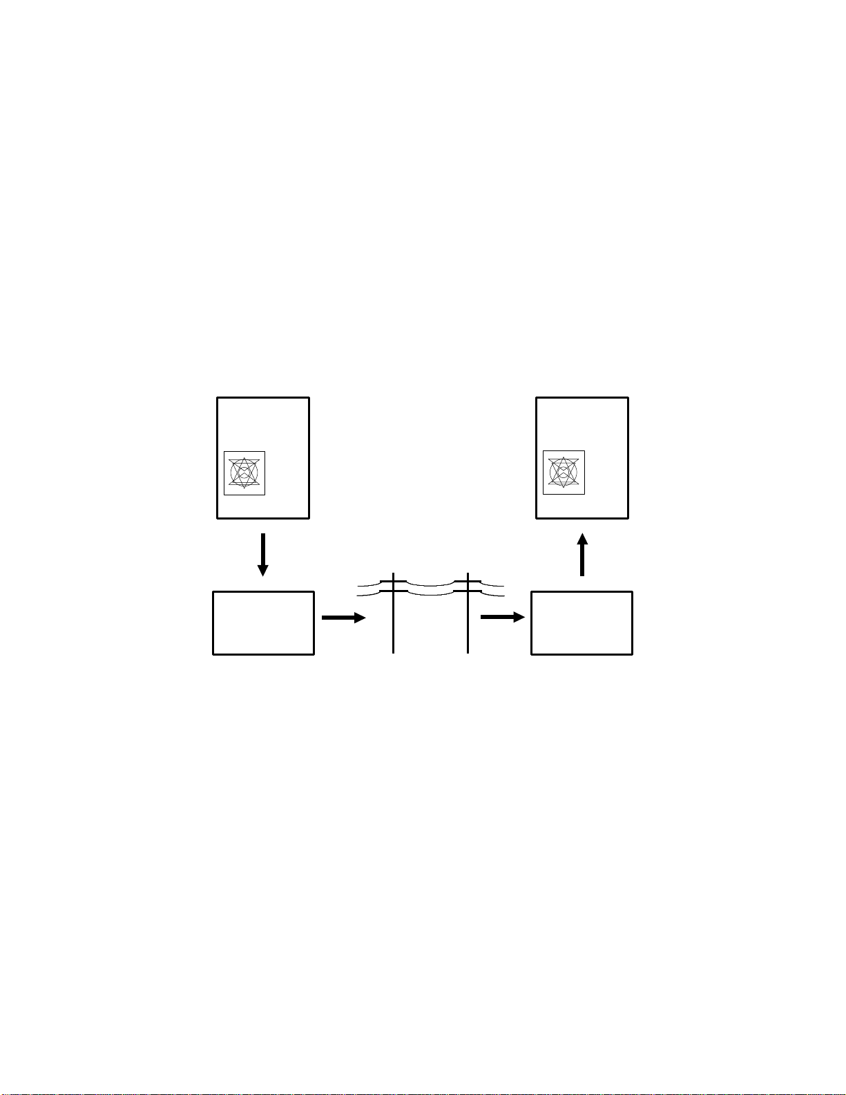
1-1-1. What is a Fax Machine?
Facsimile, commonly known as fax, is used for sending written, printed, or
graphic information from one location to another. The communication can be
across the room or across the world. A simple block diagram of fax operation
is shown below.
ORIGINAL
RECEIVED
FAX MESSAGE
--- ---- -- ---- -
------ --- ---- --
---- --- - - --- -
-- -- -
- -- --
-- -- -
- --- -
-- ---- -- --- --
SCANNING
CONVERSION
TRANSMITTING
FAX MACHINE
TELEPHONE LINE
--- ---- -- ---- -
------ --- ---- --
---- --- - - --- -
-- -- -
- -- --
-- -- -
- --- -
-- ---- -- --- --
PRINTING
CONVERSION
RECEIVING
FAX MACHINE
Facsimile machines combine scanner and printer technology with telephone
equipment to send copies to a remote location. There are three basic steps
in a facsimile transmission.
• A light source scans the writing and drawings on the original, and con-
verts the information into an electrical signal.
• This signal is sent over the telephone line to a receiving fax machine.
• The receiving machine converts the incoming signal into a copy of the
original.
Facsimile machines can transmit alphanumeric and graphic characters. Anything that can be put on paper, from handwritten notes to photographs, can
be sent by fax.
1-1-1
Page 13
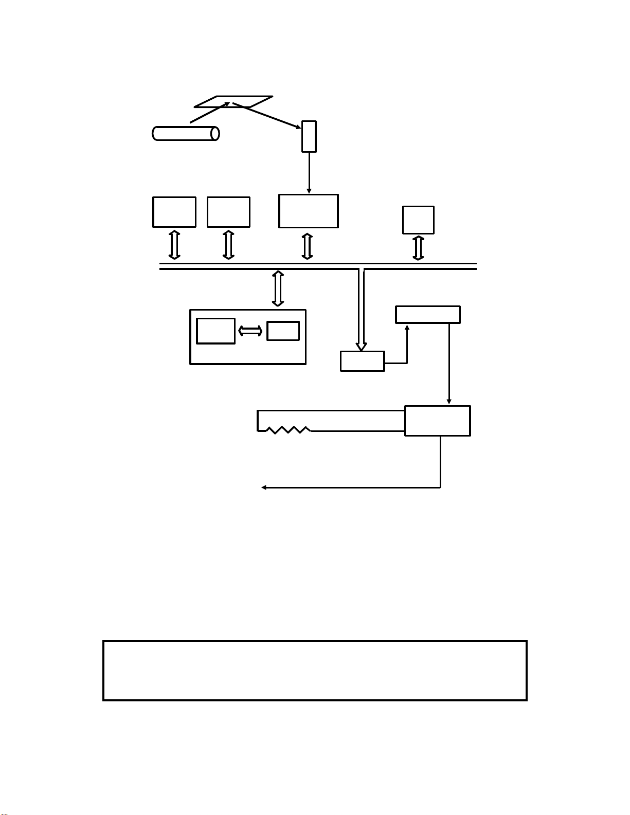
1-1-2. Thermal Paper Fax Terminals
These machines contain a thermal printer.
1. Transmitting
Exposure
[B]
Document Feed
[A]
[C]
1. Document Feed
The original (also known as the document) is fed into the scanner [A] one
page at a time.
2. Exposure
A fluorescent lamp or xenon lamp [B] illuminates the document as it passes
the exposure glass. Light reflected from the document passes to the CCD
(Charge Coupled Device). The CCD [C] converts the light reflected from the
document into an analog electrical signal.
3. Transmission
Other circuits inside the machine take the output from the CCD and convert it
into a data signal for transmission over the telephone network.
1-1-2
Page 14
2. Receiving
[C]
Cutting
[D]
Printing
[A]
Paper Feed
[B]
1. Reception of Data
Circuits inside the machine take the signal from the telephone line and convert it into a series of black and white dots for printing.
2. Paper Feed
The rx motor drives the platen roller [A], which feeds the thermal paper [B]
past the thermal head [C].
3. Printing
To print the data, the machine uses a thermal head. The thermal head consists of a line of heating elements. The paper is specially treated to make it
turn dark when heated. The received data is reproduced one line at a time as
the paper is fed past the thermal head; a black dot on the line currently being
printed is reproduced by heating the element at the appropriate location on
the thermal head.
4. Cutting
After printing, the cutter [D] automatically cuts off the received page from the
paper roll. Some machines do not have a cutter.
1-1-3
Page 15
1-1-3. Plain Paper Fax Terminals
These machines contain a laser printer. Two types of printer mechanism are
commonly used; one uses positively-charged toner, and one uses negativelycharged toner. Note the differences in charge polarities in some of the printing processes. The master unit is the centre of the printer, as shown below.
1. Transmitting
This is exactly the same as for thermal paper fax terminals.
2. Receiving
[O]
Quenching
[N]
Cleaning
Fusing
[M]
[L]
Charge
Transfer
[A]
Exposure
[C]
[J]
Registration
[K]
[D]
[E]
[B]
[G]
[F]
Development
[H]
Paper Feed
[I]
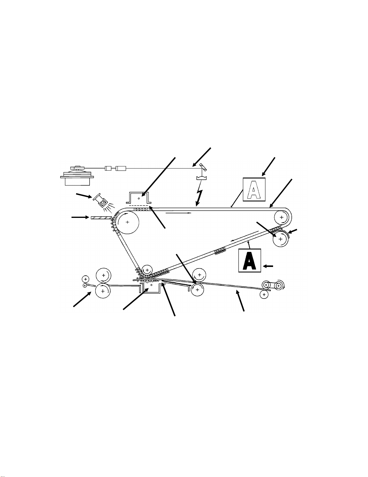
1. Reception of Data
Circuits inside the machine take the signal from the telephone line and convert it into a series of black and white dots for printing.
2. Charge
In the dark, the charge corona wire [A] gives a negative charge to the master
[B]. The grid plate [C] under the charge corona wire ensures that the charge
is applied uniformly. The negative charge remains on the surface of the master because the master has a high electrical resistance in the dark.
1-1-4
Page 16

3. Exposure
The received data signal is converted into a series of black and white dots for
printing.
Write-to-white (positive toner): To print the data, a laser beam [D] scans
across the master, switching on to make a white dot on the copy, and switching off to make a black dot.
Write-to-black (negative toner): The laser beam switches on to make a
black dot on the copy, and switches off to make a white dot.
Both types: The charge on the master goes to ground in areas exposed to
the beam, thus producing an electrical latent image [E] on the master surface.
4. Development
Write-to-white (positive toner): A thin layer of positively charged toner [F]
on the development roller [G] comes into contact with the latent image on
the master surface. Toner particles are attracted to the negatively charged areas of the master belt surface [H].
Write-to-black (negative toner): A thin layer of negatively charged toner on
the development roller comes into contact with the latent image on the master surface. Toner particles are attracted to the least negatively charged areas
of the master belt surface.
5. Paper Feed
Paper [I] is fed from the cassette. The paper is plain paper, as used in a photocopier.
6. Registration
The registration roller [J] stops the paper momentarily to correct skew, and it
allows the paper into the image transfer area [K] at the correct time.
7. Image Transfer
Copy paper is fed to the master surface while the transfer corona wire [L] applies a strong charge to the back of the paper; the charge is of opposite sign
to that of the toner. This charge pulls the toner particles from the master surface onto the paper. The paper then separates from the master and passes
into the fusing unit.
8. Fusing
In the fusing unit [M], the image is fused to the copy paper by two rollers
which apply heat and pressure.
9. Cleaning
In preparation for the next copy, the cleaning blade [N] removes any remaining toner from the master surface.
10. Quenching
The light from the quenching lamp [O] electrically neutralizes the master surface.
1-1-5
Page 17
1-2. OVERALL SYSTEM CONTROL
This section shows how a fax machine is organized and controlled. The responsibilities of each cpu and major control component are described.
The internal organization of most fax machines is very similar. Typical examples are given below. Note that the diagrams show only how the machine is
controlled; the path of video data is not explained in this section.
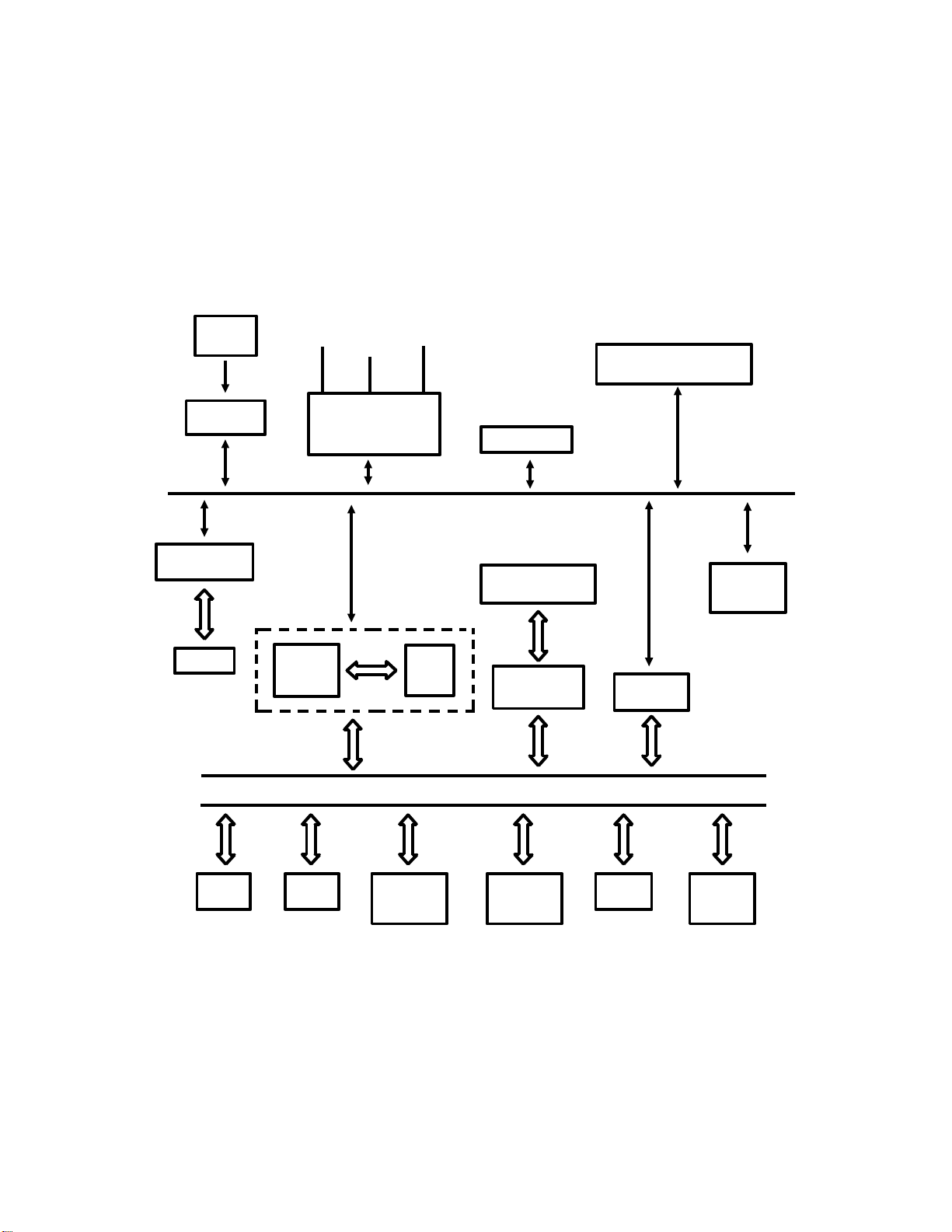
1-2-1. Thermal Paper Fax Machines
Scanner
Sensors
Operation
Panel CPU
Voice Message
Processor
Memory
External
Line Handset
Tel
Network
Interface
Circuits
CPU
CONTROL SIGNALS
I/O
Port
SBU (CCD)
Video Processing
Memory
Video
Processor
Scanner and Printer Drive
Components and Sensors
Thermal
Head
THERMAL
PRINTERS
ONLY
Modem
DATA AND ADDRESS BUS
RAMROM
SAF
Memory
ECM
Memory
FIFO
Line
Buffer
The centre of the machine is the cpu. This controls the machine. (In machines that have more than one major cpu, the controlling cpu is called the
Main CPU.) An LSI gate array called the I/O Port controls much of the machine in conjunction with the cpu. So, to simplify the diagram, the cpu and
the I/O Port are considered to be one unit.
1-2-1
Page 18

Data and address buses link the cpu to the major data processing and storage components of the machine. Control signals drive the mechanical and
electrical components of the scanner, network interface, and printer.
The components shown on the diagram on the previous page are explained
below.
ROM (Read Only Memory)
This contains the system software, which controls all aspects of the machine’s operation.
RAM (Random Access Memory)
This contains work areas for the cpu, and programmable system parameters
(such as bit switches). If the main power is switched off, the RAM is not
erased. This is because a battery supplies back-up power to the RAM if the
main power is off (see section 1-4-3 for more details on battery back-up).
Static RAM ( SRAM), Pseudo-static RAM (PSRAM), and Dynamic RAM ( DRAM)
SRAM can be connected to a battery, which provides back-up power if the main power
switch is turned off. (In some cases, a capacitor with a high charge capacity is used to
supply back-up power to the SRAM.) The power from the battery prevents the data from
being erased. SRAM is commonly used for storing vital system parameters, but may also
be used as SAF memory. However, the high cost of SRAM prevents its use as SAF
memory in low-cost fax machines.
Recently developed types of DRAM can also be backed up by a battery. However, unlike
SRAM, it needs a periodic refresh from a DRAM controller or the contents are erased. The
SAF memory in most fax machines is DRAM.
PSRAM, like SRAM, can be backed up by a battery and does not need periodic refresh.
However, PSRAM is more like DRAM in its internal structure.
SAF Memory (Store And Forward Memory)
When a user stores a fax message in the memory for sending later or broadcasting, the message goes into the SAF memory. Also, incoming confidential
messages and ’substitute’ receptions are held in this memory.
Not all fax machines have this memory. In some models with no or low SAF
memory capacity, the ECM memory may be used as a SAF memory. The exact method of use and the limitations on use differ from machine to machine.
However, generally, battery back-up is disabled while the memory is being
used for ECM.
SAF memory is usually DRAM, but the small SAF/ECM memory is usually
PSRAM.
1-2-2
Page 19

Line Buffer
This memory buffer ensures synchronization of video data transfer between
different components of the circuit (see section 1-3). If the line buffer is too
small, the scanner mechanism will have to keep stopping and starting, leading to excessive noise. A line buffer size of four or eight lines is typical.
ECM Memory (Error Correction Mode Memory)
ECM is an optional extension to Group 3 protocol that provides a more reliable way to send data over noisy lines. Using ECM, data is assembled into
protocol frames. ECM requires RAM for assembly into and extraction from
protocol frames. This memory is the ECM memory; it is normally PSRAM,
without battery back-up.
With ECM, image data is arranged in protocol frames (256 bytes in each
frame), and transmitted in blocks made up of 256 frames. Therefore, each
block is 64 kbytes. Normally, one page of compressed image data can be
sent in one block, but more than one may be needed if halftone mode was
used when scanning the original.
Single Buffer and Double Buffer ECM Memory
Single Buffer (64 kbytes): This memory is only large enough to hold one block. After
receiving a block of compressed facsimile data from the remote terminal into ECM
memory, the data is reconstructed and printed. The next block cannot be received until
printing has finished. The first block is deleted from memory after printing.
Double Buffer (128 kbytes): This memory can hold two blocks. While one block is being
printed, the next block can be received into the other half of the double buffer memory.
This ensures continuous operation, saving time and overall communication charges.
In some machines with a single buffer only, SAF memory or hard disk memory are used
to provide double buffer capability.
ECM is explained in more detail in Appendix B. For full details, see a recent
version of CCITT recommendation T.30.
FIFO Memory (First-In First-Out Memory)
The FIFO synchronizes the transfer of video data to the modem (transmission) or from the modem (reception). It also acts as a buffer, ensuring that
there is always some data for the modem to pick up, modulate, and send
out. The FIFO also has some unique functions, in addition to synchronizing
data transfer from the cpu to the modem, as explained in section 2-8.
The actual use of the FIFO and Line Buffer in each communication mode is
outlined in section 1-3.
CCD (Charge Coupled Device)
The CCD generates the video image signal. This is an analog signal.
1-2-3
Page 20

Modem
During transmission, the modem converts the data into a form that can be
sent out on the telephone line in accordance with the appropriate CCITT V-series recommendations; this process is called Modulation. During reception,
the modem converts incoming data into a form that the machine can work
with; this process is called Demodulation. The term ’modem’ is derived from
these two processes; MOdulation/DEModulation. The different types of
modulation encountered in fax machines are described in appendix F (for full
details see the CCITT V-series recommendations).
Video Processor
This contains circuits that process the output of the CCD. Using digital techniques, the quality of the image can be improved before transmission.
Video Processing Memory
Some of the digital video processing techniques require a work area.
Scanner and Printer Drive Components and Sensors
Every machine has motors, lamps, solenoids, electromagnetic clutches, sensors, and switches.
Thermal Head
This prints received images on the thermal paper.
Network Interface Circuits
The filters, relays, attenuators and other components in these circuits interface the machine with the public telephone network. These circuits ensure
that the machine connects to the line and dials in the correct way. They also
ensure that the machine and the network equipment do not damage each
other.
Voice Message Processor
This converts voice messages from analog (audio) to digital for storage in the
memory. It also retrieves the message for memory when it is needed for sending out over the telephone line.
Operation Panel
This is the ’user-machine interface’. The operation panel may have one or
two cpu’s to control the LCD, and the keys and indicators. In many models,
the operation panel cpu’s monitor the sensors in the scanner mechanism.
The operation panel may contain a microphone for storing the voice message and for making telephone conversations as part of a speakerphone;
however, the handset is normally used for these purposes.
1-2-4
Page 21
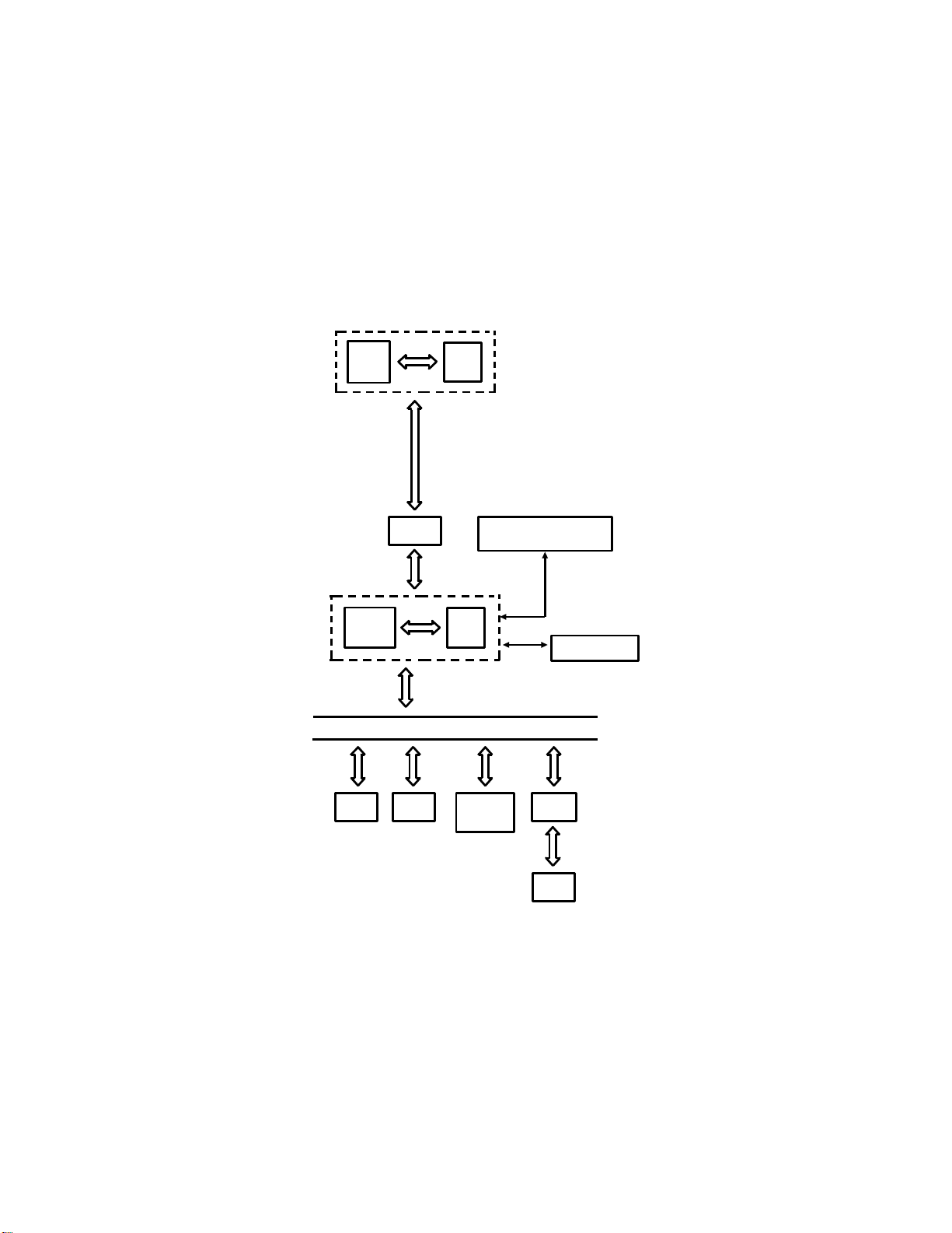
1-2-2. Plain Paper Fax Machines
Plain paper fax machines, having a laser printer engine, are more complex,
and often require more than one major cpu. The cpu that controls the machine overall is called the Main CPU (see section 1-2-1).
The areas directly controlled by the main cpu are the same those controlled
by the cpu in thermal faxes (this is the basic facsimile engine, minus thermal
head and printer components). The difference is that the printer components
are often controlled through another major cpu, known as the slave cpu, as
shown below.
Main
CPU
Slave
CPU
I/O
Port
Buffer
DATA AND ADDRESS BUS
RAMROM
Printer Drive Components
I/O
Port
Page
Memory
and Sensors
Laser Diode
LIF
RAM
The additional components are as follows.
Slave CPU
This cpu controls the laser printer engine, under the control of the main cpu.
It is assisted by an I/O Port, which is similar in function to that of the main
cpu. (In some laser faxes, some of the scanner components are also controlled by the slave cpu.)
1-2-5
Page 22

Buffer
This is an interface for commands, responses, and data passing between the
two cpu’s.
Page Memory
This memory holds one page of data for printing. Printing does not begin until the complete page has been assembled here. Data from the network
comes into the page memory through the modem (or from the SAF memory
in the case of substitute or confidential reception), under the control of the
main cpu.
LIF (Laser Interface)
When a complete page has been assembled in the page memory, it passes
to the LIF. The LIF controls transfer of data from the page memory to the laser diode. It also contains data processing circuits, including those for
smoothing the data to 16 x 15.4 dots/mm before printing.
RAM
The LIF uses this memory as a work area for data processing.
ROM
This contains printer control software.
Laser Diode
The machine writes the image on the master by switching a laser beam
on/off. A laser diode generates this laser beam.
Printer Drive Components and Sensors
A laser printer mechanism is more complex than a thermal printer. The components of a laser printer will be explained in section 4.
Hard Disk
Some machines have a hard disk instead of a RAM SAF memory. The hard disk may also
store system parameters, Quick Dial Codes and so on.
1-2-6
Page 23
1-2-3. Communication Between CPU’s
Most machines have more than one cpu, but most of these are of minor importance, controlling certain areas of the machine, such as the operation
panel. The major cpu’s control the machine, but delegate responsibilities to
the other cpu’s. In thermal fax machines, there is one major cpu (called the
cpu). Laser fax machines often have two major cpu’s; the overall controlling
cpu is called the main cpu, and the other is called the slave cpu.
The number of cpu’s and their areas of responsibility vary from model to
model, so descriptions of circuits in this manual will be very generalized.
Communication between cpu’s is normally done in one of two ways; a serial
interface or a parallel interface. These are outlined below.
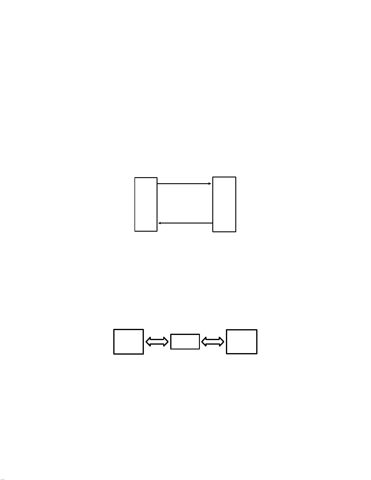
1. Serial Interface
COMMANDS
Main
CPU
RESPONSES
Slave
CPU
The serial interface most commonly used between two cpu’s consists of a
command line from the main cpu, and a response line from the slave cpu.
There may also be a clock signal to synchronize the interface, and a reset signal.
Serial interfaces are often used when the slave cpu shown in the diagram is a
minor cpu for monitoring sensors and controlling mechanical components.
2. Parallel Interface
Main
CPU
Buffer
Slave
CPU
A parallel interface typically has 8 or 16 wires for carrying data between the
two cpu’s. Data can pass in either direction on these wires. A buffer is normally included between the two cpu’s.
A parallel interface is normally used when the cpu is receiving and processing video data, as well as controlling mechanical components. A typical example would be between the main and slave cpu’s in a laser fax machine.
1-2-7
Page 24
1-3. VIDEO DATA PATH
This section outlines the path of video data through the machine in transmission, reception, and copying modes.
1-3-1. Transmission
This section explains the path of data through the machine during transmission. The main description is for memory transmission with ECM. Following
this main description are diagrams showing the differences between memory
transmission with ECM and the following:
• Memory transmission without ECM
• Immediate transmission with ECM
• Immediate transmission without ECM
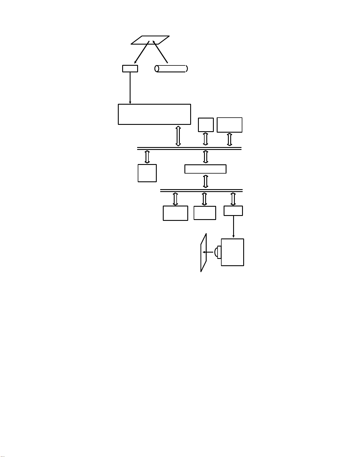
1. Scanning
Scanner
Fluorescent Lamp
Shading Plate
Shading Plate
CCD
Lens Block
Profile
When the user presses the Start key on the operation panel, the original
(also known as the document) passes into the scanner, where it is illuminated
by the fluorescent lamp.
Light is reflected from the document through a shading plate, which allows
more light to pass through from the ends of the lamp than from the centre;
this compensates for the fact that the ends of the lamp are not so bright as
the centre.
Other types of lamp
Xenon lamp : If a xenon lamp is used, the difference in brightness is smaller than with a
conventional fluorescent lamp, and the xenon lamp is brighter, but this problem still exists.
LED array: This is a strip of photodiodes. As all the diodes are equally bright, a shading
plate is not needed.
After passing through the shading plate, the light is focused by the lens block
onto the CCD.
1-3-1
Page 25
2. Data Processing
Fluorescent
Lamp
Original
CCD
Analog Signal
ECM
Memory
SAF
Memory
Line
Buffer
To the
Network
Processor
FIFO
RAM
Variable Resistor
Video
CPU
8-bit
Attenuator
Modem
Gain Control
Circuit
CCD and Analog Video Processing
The CCD (Charge Coupled Device) is a row of photoelectric elements. It generates an analog video signal from the light reflected from the document. This
signal passes to the Video Processor, which corrects the data for scanner irregularities and converts it to digital (the signal from each element of the
CCD is typically represented by four bits).
For more about CCDs, see Appendix D.
Contact Image Sensor
In some cheaper models, a contact image sensor (CIS) is used instead of a CCD. The
image sensor is directly below the exposure glass; no mirrors, lenses, or shading plates
are used (the image sensor elements are self-focusing).
1-3-2
Page 26

Digital Video Processing
The Video Processor also does digital video data processing (e.g., halftone,
MTF), and converts the data to eight-bit parallel.
If the original is wider than the paper in the printer at the other end, data will
be deleted in the main scan and sub-scan directions to make the data fit on
the paper at the other end. This process is known as reduction.
After video processing, the signal from each CCD element is represented by
one bit (unless reduction was done).
See section 2-3 for full details on video data processing.
Storage to SAF Memory
After leaving the Video Processor, the data is compressed and then stored in
the SAF memory. The compression method used varies from model to
model. A simple compression technique such as MH gives fast data storage,
but the data takes up more room in the memory. More complex compression
techniques such as MR or MMR compress the data more effectively so that
less memory space is used, but they increase the scanning time.
Retrieval from SAF Memory
When it is time to send the data, the data comes out of the memory into the
cpu. The cpu reconstructs the raw data, and passes it to the line buffer.
(Lines of data that were stored as uncoded data go from the memory straight
to the line buffer.)
Compression
The cpu then compresses the data in accordance with the method agreed in
the set-up protocol that was exchanged between the two machines.
ECM Data Frame Assembly
Using the ECM memory, the cpu assembles the data into ECM data frames,
which are sent to the modem and the line.
Modulation
The modem converts the data to serial and modulates it.
Attenuation
The data then passes through an attenuator, which adjusts the tx level (this is
the output power of the data signal). It then passes through a variable resistor on the NCU, which can be used to adjust the tx level. The data then
passes to the network.
Flow charts for the different transmission modes are given on the next page.
1-3-3
Page 27
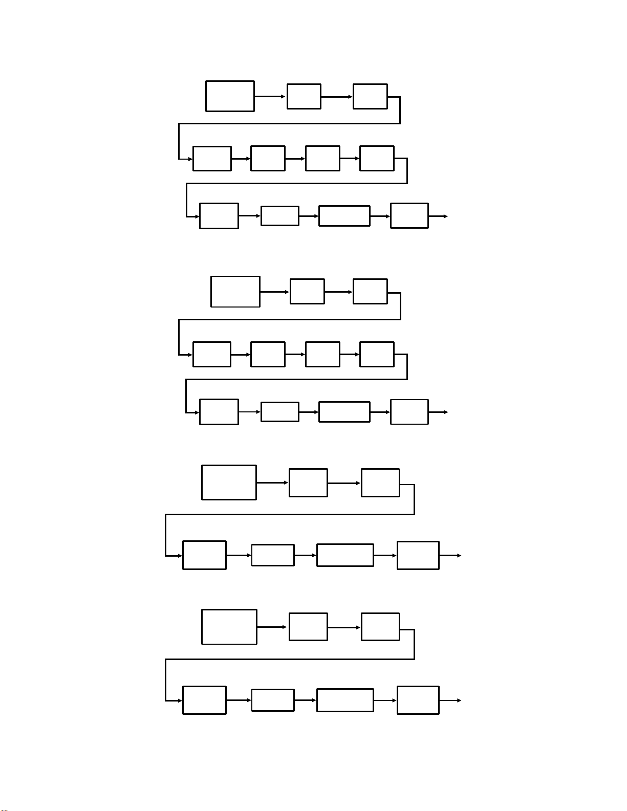
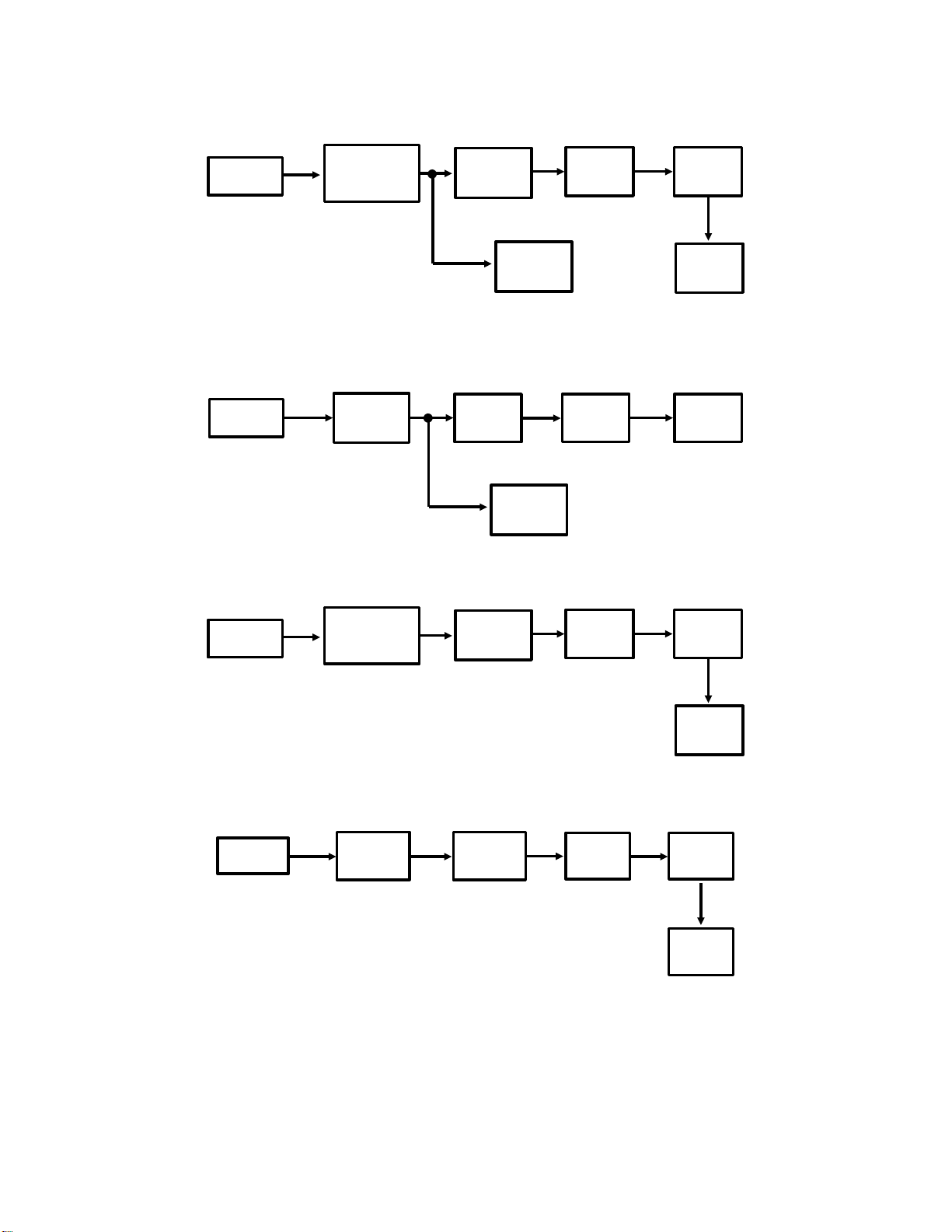
1. Memory Transmission, with ECM
Video
Processor
Reconstruction Compression
SAF
Memory
Line
Buffer
Line
Buffer
Compression
CPU
CPUCPU
ECM
Memory
Modem Attenuator
2. Memory Transmission, without ECM
Video
Processor
Reconstruction Compression
SAF
Memory
FIFO
Memory
CPU CPU
Modem Attenuator
3. Immediate Transmission, with ECM
Video
Processor
Line
Buffer
Buffer
Line
Buffer
Gain
Control
Compression
CPU
Line
Gain
Control
Compression
CPU
ECM
Memory
Modem Attenuator
4. Immediate Transmission, without ECM
Video
Processor
FIFO
Memory
Modem Attenuator
Line
Buffer
1-3-4
Gain
Control
Compression
CPU
Gain
Control
Page 28
1-3-2. Reception
This section explains the path of data through the machine during reception.
The data paths for thermal printers and laser printers are explained separately.
The main description is for basic reception without ECM. Following this main
description are diagrams showing the differences between basic reception
with ECM and the following:
• Basic reception without ECM
• Memory reception without ECM
• Memory reception with ECM
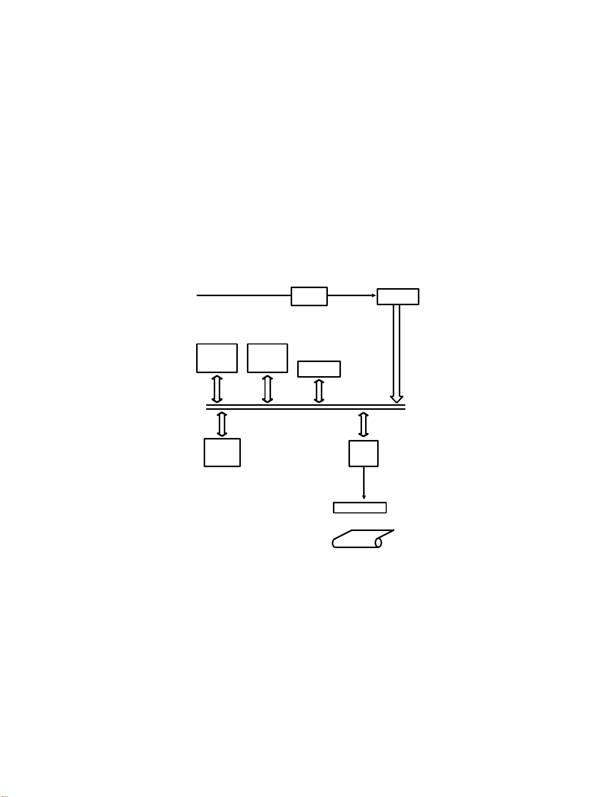
1. Thermal Printers
From the
Network
SAF
Memory
Line
Buffer
ECM
Memory
Filter
I/O Port
Thermal
Head
Modem
CPU
Thermal
Paper
Data from the line passes through a filter to remove unwanted frequencies.
Then it goes to the modem, which demodulates the data and converts it to
parallel.
1-3-5
Page 29

Reconstruction
The data coming from the modem is compressed data. This data passes
from the modem through the FIFO memory to the cpu where it is decoded,
using the line buffer.
Note: In machines with SAF memory, the data is also stored in the memory
in case the printer jams or runs out of paper; after the user corrects
the fault, the message will be printed out from the memory and no
data will be lost. However, in some models, if the paper ends but the
paper end sensor did not detect a black stripe at the end of the roll,
the page being printed will be lost.
Smoothing
The cpu then smooths the data, to remove jagged edges from the data. The
resolution of the received data is upgraded into the highest that the printer
can print; this is typically 8 x 7.7 dots per mm.
Printing
The cpu converts the data to serial, and passes it to the thermal head
through the line buffer.
1-3-6
Page 30
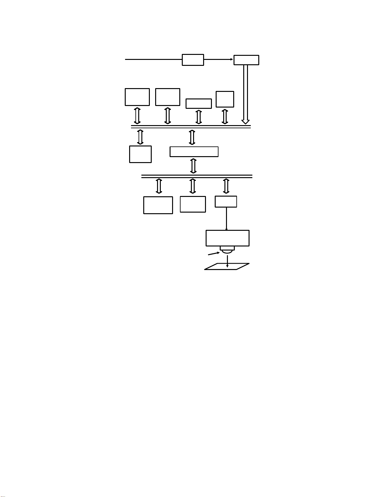
2. Laser Printers
From the
Network
SAF
Memory
Line
Buffer
ECM
Memory
Page
Memory
Filter
I/O Port
Buffer
Slave
CPU
Modem
Main
CPU
LIF
Laser Diode
Driver
Laser Diode
Copy Paper
Data from the line passes through a filter to remove unwanted frequencies.
Then it goes to the modem, which demodulates the data and converts it to
parallel.
Reconstruction
From the modem, the data goes to the SAF memory, where it is held in case
the printer jams or runs out of paper or toner; after the user corrects the fault,
the message will be printed out from the memory and no data will be lost.
The data coming from the modem is compressed data. From the SAF memory, the data passes to the cpu where it is decoded using the line buffer.
1-3-7
Page 31

Page Assembly
The data then goes through the slave cpu to the page memory. When a full
page of data has been assembled in the page memory, the data goes to the
LIF (Laser Interface). If the page is too long for the paper in the cassette, the
data is split into two pages and/or reduced in the page memory.
Smoothing
The LIF smooths the data. Smoothing removes jagged edges, converting the
resolution of the received image into the highest resolution that the printer
can accept. This is typically 8 x 15.4 dots per mm or 16 x 15.4 dots per mm
for a laser printer.
The LIF converts the data to serial before passing it to the laser diode.
Printing
The laser beam switches on/off in accordance with the data signal, and forms
a latent image on the master surface. This latent image is developed with
toner, the toner is transferred to copy paper, and finally the toner is fused to
the copy paper.
Flow charts for the different reception modes are on the next page.
1-3-8
Page 32
1. Basic Reception with ECM
Reconstruction
Modem
ECM Data
Extraction
2. Basic Reception without ECM
Modem
FIFO
Memory
3. Memory Reception with ECM
ECM
Memory
SAF
Memory
Reconstruction
Main
CPU
SAF
Memory
Main
CPU
Line
Buffer
Reconstruction
Line
Buffer
Printer
Engine
Printer
Engine
Modem
ECM Data
Extraction
4. Memory Reception without ECM
Modem
FIFO
Memory
SAF
Memory
SAF
Memory
Main
CPU
Reconstruction
Main
CPU
Line
Buffer
Printer
Engine
Line
Buffer
Printer
Engine
1-3-9
Page 33

1-3-3. Copying
Basically, the data path for copying is a hybrid of the scanner and printer circuits. The data paths for thermal printers and laser printers are shown below.
1. Thermal Printers
Original
CCD
Fluorescent
Lamp
Video
Processor
SAF
Memory
Line
Buffer
Thermal
Head
CPU
Thermal
Paper
Single Copy
The data from the Video Processor passes to the cpu. The cpu converts the
data to serial and passes it to the thermal head.
Multi-page Copying
This can only be done in machines with SAF memory (it may be disabled in
the factory, because this function can cause stress to the thermal head).
Data from the Video Processor passes to the cpu where it is compressed
and stored in the SAF memory. To print the page, the data comes out of the
SAF into the cpu, which decodes the data and sends it to the thermal head.
1-3-10
Page 34
2. Laser Printers
CCD
Fluorescent
Video
Processor
Lamp
Original
Main
CPU
SAF
Memory
Line
Buffer
Page
Memory
Copy Paper
Buffer
Slave
CPU
LIF
Laser
Diode
Driver
Single Copy
The data from the Video Processor passes to the cpu. The cpu converts the
data to serial and passes it to the page memory and the laser printer.
Multi-page Copying
Data from the Video Processor passes to the cpu where it is compressed
and stored in the SAF memory. To print the page, the data comes out of the
SAF into the cpu, which decodes the data and sends it to the page memory
and the laser printer circuit.
1-3-11
Page 35
1-4. POWER DISTRIBUTION
This section explains power distribution in a typical fax machine. It also explains features such as battery back-up, power supply activation in standby
mode, and safety measures such as interlock switches.
1-4-1. Typical Power Distribution Circuits
Fax machines require a main power supply of 230 ±10V, 50 Hz.
The Power Supply Unit (PSU) generates the voltages needed by the machine
from the ac main power supply and passes them to the main PCB, which is
commonly called the FCU. There may be some regulators on the FCU to generate additional power supplies, as shown in the following example. The FCU
distributes the voltages to the components of the machine. However, the supplies to the thermal head (thermal printers) and the fusing unit and PSU fan
(laser printers) normally come straight from the PSU.
The following diagrams show some typical circuits. The components used differ from model to model.
1. Thermal Printer Fax
Thermal
Head
+24VD
PSU
+5V
Printer
Sensors
+5V
+24VS
+24VD
-12V
+5V
Tx Motor
Rx Motor
ADF Clutch
Document Feed-out Clutch
Stamp Solenoid
Fluorescent Lamp Driver
Cutter Motor
+24VD
Modem
+5V
- 12V
+12V
+5V
Regulator
+24VD
Regulator
+24VS
FCU
+24VS
- 12V
NCU
+12V
- 5V
- 5V+5V
+5V
MBU
+5V
- 5V
SBU
OPU
+5V
Scanner
Sensors
+12V
+5V
1-4-1
Page 36

2. Laser Printer Fax
Tx Motor
Master Belt Drive Motor
ADF Clutch
Document Feed-out Clutch
Stamp Solenoid
Quenching Lamp
Fluorescent Lamp
Pentagonal Mirror Motor
PSU Fan
+24VS
AC Main
Power
Fusing
Lamp
Thermistor
+5V
+24VD
PSU
Master Unit
Interlock Switch
+24VD
+5V
+24VS
+24VD
-12V
+24V
+5VS
+5V
Modem
- 12V
+5V
+12V
+5V
+24VD
Laser Diode
S5V
+24VD
+5V
Regulator
Regulator
LDDR
S5V
-12V
UIB
+24VS
FCU
+24VS
- 12V
LSD
NCU
+12V
- 5V
+5V
-12V
- 5V+5V
Sensors:
Document
Document Width
+5V
Scan Line
Scanner Cover Switch
Toner Overflow Sensor
+5V
MBU
+5V
- 5V
SBU
OPU
Power Pack
+12V
+5V
+24VD
Upper Unit
Interlock Switch
Right Cover
Interlock Switch
+5VS
+24VD
Registration Sensor Board
+24VD
Charge and Transfer Corona Fans
Registration Clutch
Upper Paper Feed Solenoid
Upper Paper Lift Solenoid
+5V
+24VD
1-4-2
+24VD
Main Motor
+5V
Fusing Unit Fan
Sensors:
Copy Feed-out
Right Cover Switch
Paper End
Paper Near-end
Paper Height
Toner End
Paper Size
Page 37

1-4-2. Power Supply Activation
In most models, the motors, solenoids, and electromagnetic clutches need a
+24V supply. When the machine is on standby, this power supply is not
needed. However, +24V is needed during standby mode, (see section 2-10-
1). So, in most fax machines (but not all), the +24V supply is divided into two
channels. The +24VS channel supplies the power needed during standby
mode, and the +24VD supply powers the motors and so on.
Note
In some models, the +24VD supply is kept on permanently, and there is no +24VS power
supply.
PSU
+24V
+24VD
A
+24VD
CPU
B
During standby, +24VD is switched off. When the cpu detects an incoming
call, or a document being placed in the feeder, the cpu turns on +24VD. It
does this by sending the +24VD activation signal [A] high.
The cpu switches off +24VD when the machine returns to standby. In some
models, the cpu will also switch +24VD off when it detects that certain covers
are open; this avoids exposing a user or technician to hazardous voltages.
In some laser printers, the machine also switches on +24VD when the fusing
lamp temperature falls below a certain level (e.g., 65 °C) in standby mode;
the fusing lamp is kept at a fairly high temperature during standby so that the
warm-up time is kept to a minimum. The +24VD supply drives the ac switching circuit that transfers power to the fusing lamp; see section 4-7 for details.
1-4-3
Page 38

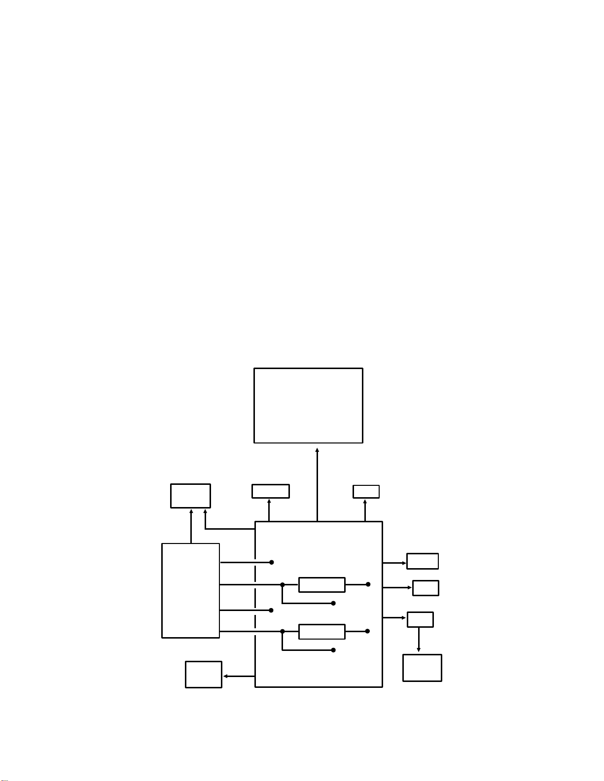
1-4-3. Memory Back-up
Circuit Type 1: SRAM SAF and Parameter Memory
+5V
Switching
Voltage
Detector
+5V
Circuit
Real Time Clock,
RAM,
Voice Message
Memory, and
DRAM Controller
Battery
Switch
Battery
1
+24V
Battery
Switch
Switching
Circuit
Regulator
Voltage
Detector
Battery
2
[A]
Memory
Monitor
SAF
Memory
[B]
To avoid loss of data when the power is switched off, there are back up circuits for the SAF memory, the voice message memory, the system parameter
RAM, DRAM controller, and the real time clock in the cpu. Battery 1 backs up
the system parameter RAM and voice message memory, and keeps the real
time clock going. Battery 2, which is rechargeable, backs up the SAF memory.
The DRAM controller periodically refreshes the contents of the DRAM, even
while the main power is off, so that data is not lost.
1-4-4
Page 39

When the main power is on, +5V powers the memories, the DRAM controller,
and the real time clock. The +24V supply keeps Battery 2 fully charged. The
cpu keeps the SAF memory back-up circuit off while there is no data in the
SAF memory. The cpu controls the SAF back-up circuit through a memory
monitor device, which also operates when the main power has been
switched off.
When the main power is switched off, the function of the back-up circuit depends on whether there is any data in the SAF memory.
If there is no data in the SAF, the memory monitor disables SAF memory
back-up [A]. However, battery 1 backs up the parameter RAM, clock, and
voice message memory.
If there is data in the SAF, the memory monitor enables SAF memory back-up
[A] and Battery 2 backs up the SAF memory. Battery 2 also backs up the
RAM, clock, DRAM controller, and voice message memory; this increases the
lifetime of battery 1, which is not rechargeable. If the back-up voltage at the
SAF falls below 4.5 Volts, signal [B] to the memory monitor changes state.
The memory monitor then disables SAF memory backup (signal [A] in the
diagram on the previous page), and battery 1 will start to back up the RAM,
clock, DRAM controller, and voice message memory. The battery cannot reliably back up the SAF memory if the voltage falls below 4.5 V.
Battery Switches
During operation, the battery switches must always be on. If the switches are not kept on,
the contents of the memory will be lost if the main power is turned off. When the PCB
with the battery is removed, the battery switch can be turned off.
In some models, there is only a small SAF memory (normally a PSRAM),
which also acts as an ECM memory. If ECM data enters the SAF memory,
the cpu will instruct the memory monitor to disable SAF memory back-up (signal [A] in the diagram on the previous page).
1-4-5
Page 40
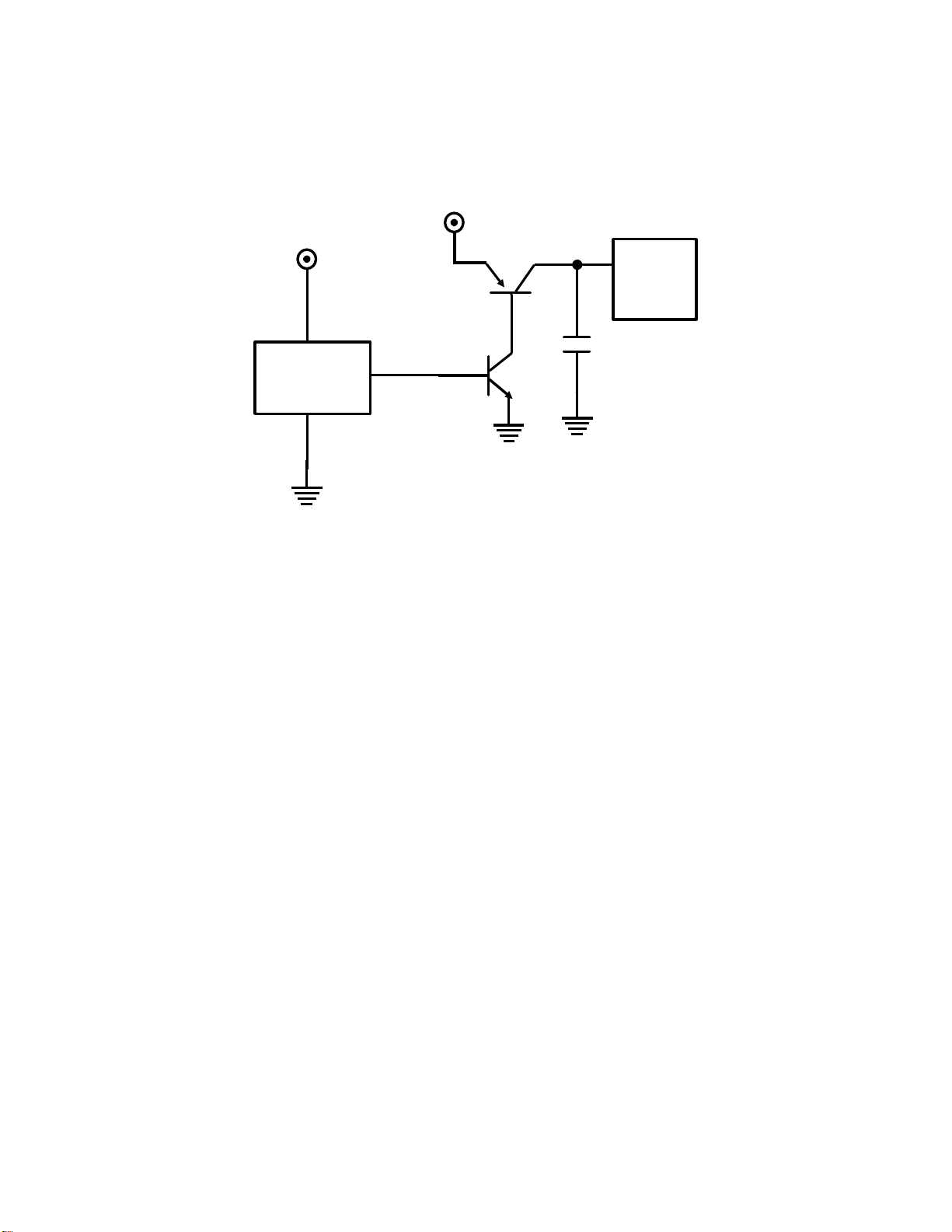
Circuit Type 2: Capacitor Back-up for Small SAF Memories
Some models that only have a small SAF memory. This memory also func-
tions as the ECM memory. In many cases, this small SAF memory is backedup by a charged capacitor instead of a battery.
+5V
+5V
Small
SAF
Q2
+
Memory
Voltage
Detector
A
Q1
When the main power is on, signal A from the voltage detector is high. Q1
and Q2 turn on, and the +5V supply powers the small SAF memory. At the
same time, the +5V supply charges the capacitor. The power must be on for
a certain time (typically about 10 minutes) before the capacitor is fully
charged.
If the main power goes off, the charge in the capacitor can back up the small
SAF memory for about 5 minutes.
As explained for Circuit Type 1, back-up is disabled when the small SAF memory is being used for ECM.
1-4-6
Page 41
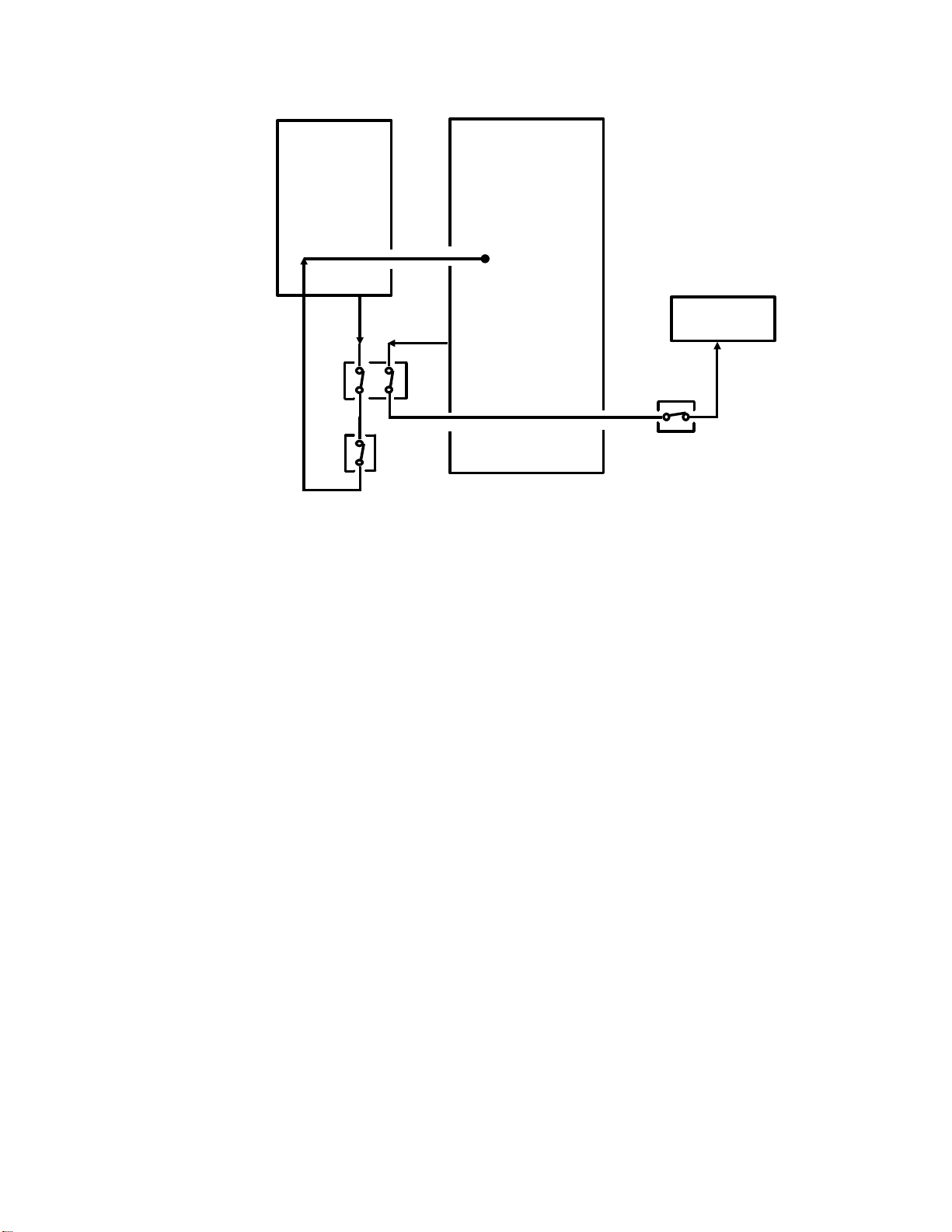
1-4-4. Interlock Switch Safety Circuits in Laser Faxes
FCU
Laser Diode
Driver
+5VLD
+5VS
Master Unit
Interlock Switch
+24VD
Upper Unit
Interlock Switch
Right Cover
Interlock Switch
PSU
+24VD
+24V
+5V
In laser fax machines, the +24VD supply powers the high voltage components of the machine. Because of this, interlock switches or microswitches
are installed to break the +24VD supply if any of the covers are opened. This
prevents the user from becoming exposed to high voltages at the charge and
transfer coronas and the development unit if the covers are opened.
The interlock switches are safety features, cutting off +24VD (for the power
pack and other components) and +5VLD (for the laser diode). In the example shown above, the switches operate as follows; some models are simpler.
• Upper unit interlock switch: Open when either the upper unit or the
copy exit cover are open; breaks the +24VD and +5VS supplies.
• Right cover interlock switch: Open when the right cover (by the develop-
ment unit) is open; breaks the +24VD supply.
• Master unit interlock switch: Open when the upper unit is open or when
there is no master unit; breaks the +5VLD supply.
Note that power to the laser diode driver is cut if the user opens the upper
unit or removes the master; these actions open the master unit interlock
switch, and cut the power to the laser diode driver.
If the scanner cover is opened, the +24VD supply is cut by the cpu in some
models; the +24VD supply does not usually pass through the scanner cover
switch. If the machine has a lower cassette installed, the cover switches in
the lower cassette do not usually affect the +24VD supply.
1-4-7
Page 42

SECTION 2. TRANSMISSION
This section explains how the machine sends a fax message. It covers document feed and scanning, video data processing, and the communication control circuits for transmission.
When they leave the factory, most machines that have memory are set up for
automatic dialling and transmission from memory. Sections 2-1 to 2-9 are
based on the steps taken by this type of machine. Other modes, such as
transmission without memory, send later, automatic dialling from behind a
PABX, and manual dialling will be explained separately in sections 2-10 and 2-
11.
Below, there follows a brief outline of the individual steps for memory trans-
mission with automatic dialling. These steps are basically the same for most
machines.
Document Detection (Section 2-1) - The user places the document in the
feeder, and the cpu turns on the fluorescent lamp when it detects the document.
Document Feed (Section 2-2) - The machine feeds the document through
the scanner.
Video Processing (Section 2-3) - The machine scans the document, converts the scanned data to digital, and passes it through the video processing
circuits.
Call Collision Prevention (Section 2-4) - After the document has been
scanned, the machine checks whether a fax message is coming in. (The machine cannot dial while a message is coming in.)
DC Loop Closure and Line Monitoring (Section 2-5) - If there is no incoming call, the machine closes the circuit between itself and the telephone exchange. The machine will monitor the line for dial tone and/or line current if
required by local conditions (this is required in some European countries).
Dialling (Section 2-6) - The machine dials the other party.
Signal Detection (Section 2-7) - The machine then waits for a signal from
the other party before going into tx mode, if required by local conditions (this
is required in some European countries).
Data Transmission (Section 2-8) - The data passes from the memory out to
the line through the modem and network interface circuits.
Return to Standby (Section 2-9) - The machine returns to standby mode.
Page 43
2-1. DOCUMENT DETECTION
2-1-1. Document Table Mechanism
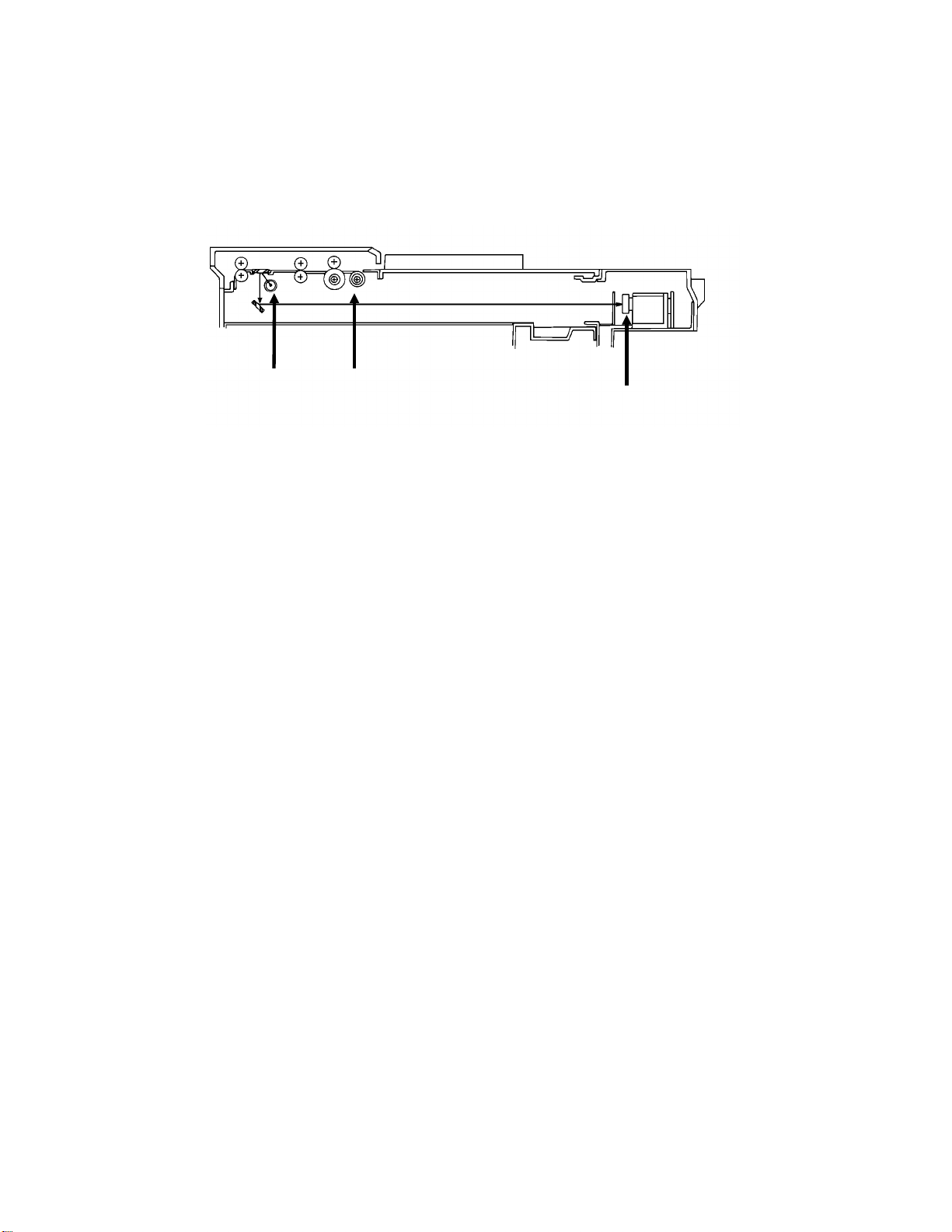
1. Sensors
The first step in sending a fax message is to place the document in the document feeder. This section explains how the machine detects when the user
has placed a document in the feeder.
The following diagram shows a typical document table mechanism.
[B]
[C]
[A]
The document feeder entrance has sensors to detect the document.
Machines that only accept A4-width [8.3"] paper only have one sensor. This
is the document sensor [A].
Machines that accept B4-width [10.1"] paper also have a B4-width document
sensor [B]. Machines that accept A3-width [11.7"] paper have a B4 document sensor and an A3-width document sensor [C].
2-1-1
Page 44

[B]
[A]
[C]
The document sensor is usually a photointerrupter. When a document is
placed in the feeder, the document pushes the document sensor actuator [A].
The B4-width document sensor and the A3-width document sensor are also
usually photointerrupters. Documents B4 width or wider push the B4-width
document sensor actuator [B] and documents A3 width or wider push the B4width and A3-width [C] document sensor actuators.
Why is document width detection necessary?
Document width detection is necessary in machines with document feeders that can
accept wide originals. This is because some machines cannot print received documents
that are wider than A4-width [8.3"]. If such a machine receives a page wider than this,
only the central A4-width would be printed. Clearly, this is not acceptable, so the
message width must be reduced to fit on the paper in the printer.
The cpu in the sending machine determines the type of reduction that is needed by
comparing the outputs of the document width sensors with the width of copy paper in the
remote terminal (this is informed in the protocol exchanged between the two terminals at
the start of communication). The sending machine normally does the reduction.
For more on reduction, see section 2-3-7.
2-1-2
Page 45

2. Document Guides
[A]
The document guides [A] are connected to each other by a rack and pinion
system. If one is moved, the other moves. The document guides ensure that
the pages are fed in without skewing.
2-1-3
Page 46

3. Shutter
[A]
[C]
[D]
[B]
Some machines, especially those with a high-capacity document feeder,
have a shutter mechanism. This mechanism prevents the user from forcing a
document too far into the feeder, which could lead to double feeding. When
the machine is in standby mode, the shutter [A] is down, preventing the user
from pushing paper into the scanner past the pick-up roller [B]. When the
pick-up roller lifts up, the shutter lifts to allow paper past the pick-up roller.
In this typical example, a tab [C] on the document feed roller shaft [D]
pushes up the shutter as the pick-up roller lifts up. When the pick-up roller
drops, the shutter blocks the document feed path again. See section 2-2 for
details about the document feed mechanism and the pick-up roller.
2-1-4
Page 47

2-1-2. Scanner Lamp
Fluorescent Lamp Driver
A B
+24VD
CPU
FCU
When the cpu detects a document at the document sensor, it turns on the
+24VD supply as explained in section 1-4.
At about the same time, it turns on the lamp, which illuminates the document
(the scanner reads the document by converting the light reflected from the
document into a video signal).
When a fluorescent lamp is used, the cpu drops pin A to low to preheat the
fluorescent lamp. After 2 s, the cpu drops pin B to low to light the lamp.
Instead of a fluorescent lamp, a xenon lamp or LED array may be used. Xenon lamps and LED arrays do not need preheating. Document feed usually
begins shortly after the lamp is switched on.
The different types of lamp used in fax machine scanners are briefly discussed in Appendix D.
Cross-references
Photointerrupters: Appendix D
LED arrays, Xenon lamps, Fluorescent lamps: Appendix D
+24VD power supply: section 1-4-2 Document feed mechanism: section 2-2
Reduction: section 2-3-7. Protocol: Appendix B
2-1-5
Page 48

October 15th, 1991
2-2. DOCUMENT FEED AND SEPARATION
Memory transmission: After the user presses Start, the document is fed in.
It stops at the auto shading position, and is then scanned and stored into
memory.
Immediate transmission: After dialling and handshaking with the other terminal, the machine starts to feed the document into the scanner. The document
is scanned and transmitted. Immediate transmission is outlined in section 210-2.
Memory transmission is the default mode of most machines, and this will be
described below in detail.
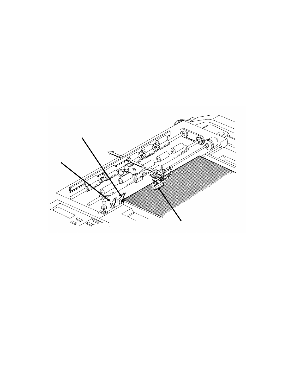
2-2-1. Pick-up and Feed
1. Overview
After the user has pressed the Start key, the machine starts to feed the document into the scanner. The pick-up and feed mechanism must feed the document into the scanner one page at a time. The mechanism must also
minimize the gap between pages during scanning, to reduce the user’s communication costs (immediate transmission) or the time needed for scanning
(memory transmission).
Document feed mechanisms have at least the following components.
• Tx motor - This stepper motor drives the scanner.
• Scan line sensor - This detects when the leading edge of the docu-
ment is approaching the auto shading position.
• Document pick-up roller - This picks up the first page of the document
and passes it to the document feed roller.
• Document feed roller - This feeds the page into the scanner.
• Document separation roller - This makes sure that only one page at a
time goes into the scanner.
• Marker (Stamp) - This makes a mark on the reverse side of the docu-
ment to inform the user of successful scanning or storing of the page.
Not all models have this component.
Some mechanisms are more complex, and have more components, as will
be seen in the following pages.
The surfaces of the document feed path are treated with antistatic material to
prevent dust from accumulating, which would lead to errors such as nonfeed.
2-2-1
Page 49

October 15th, 1991
There are some other terms to understand.
• Auto shading position - When the leading edge of the document
reaches this location (a short distance before the scan line), the scanner stops and the machine scans a white strip which is directly above
the scan line. The white level scan line taken here is used to correct the
scanned image data for scanner irregularities (see section 2-3-3).
• Scan line - This is directly above the CCD. The image data is read here.
Pick-up Rollers
Rubber pick-up rollers harden when they feed documents that have traces of silicone oil
on them (some photocopiers use silicone oil in their fusing units). Because of this, some
models are supplied with two pick-up rollers; the rubber roller, and a metallic roller with a
rough surface.
The metallic roller is not affected by silicone oil. However, it may lead to document
damage if the user pulls documents out of the feeder without opening the cover. Also, in
some models, the metallic pick-up roller leads to a drop in the number of sheets that can
be placed in the feeder.
There are two basic types of document feed mechanism.
• Mechanical clutch mechanism
• Electromagnetic clutch mechanism
2-2-2
Page 50
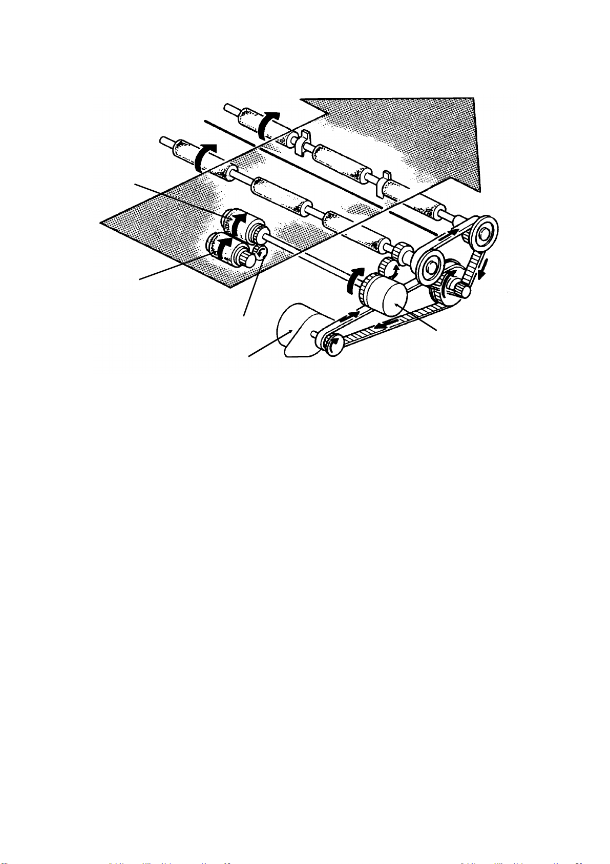
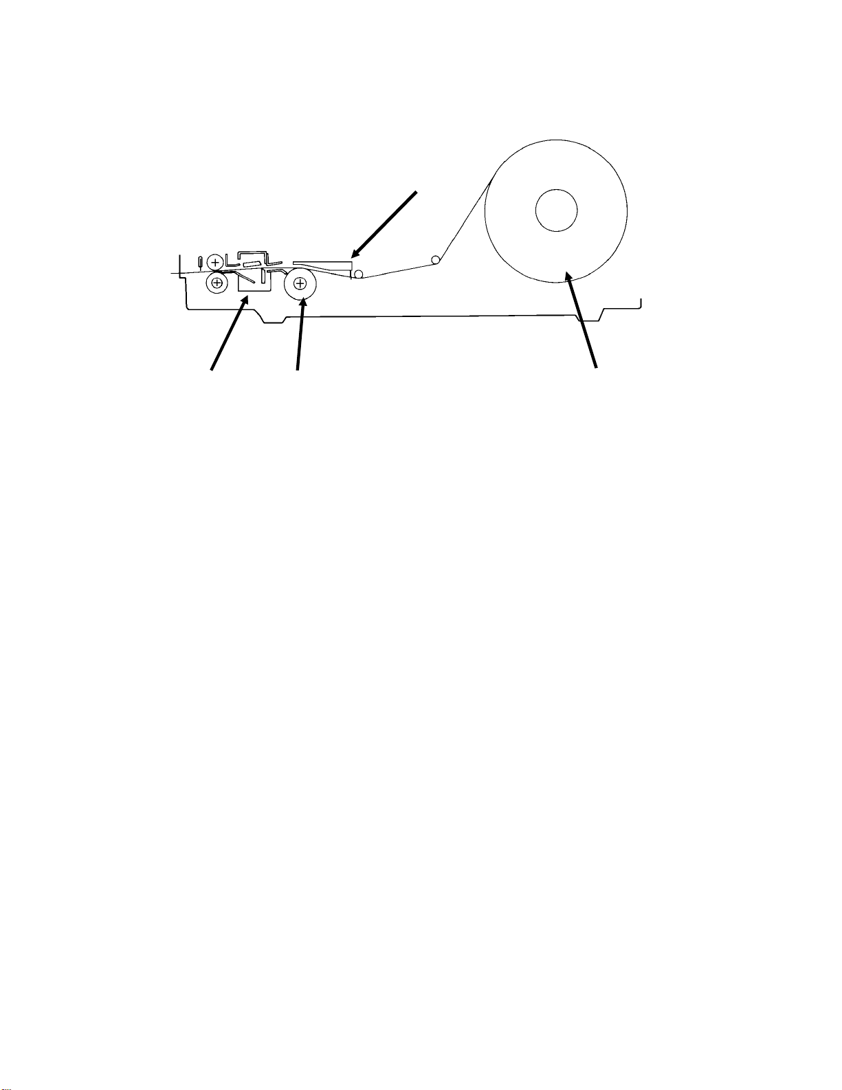
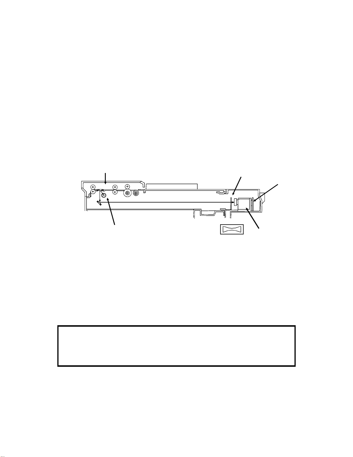
2. Electromagnetic Clutch Mechanism
Separation
Roller
Pick-up
Roller
Feed Roller
October 15th, 1991
ADF Clutch
Tx Motor
A typical electromagnetic clutch mechanism is shown above. In addition to
the major components listed on page 2-2-1, a mechanism of this type will
contain an ADF clutch and possibly one of the other two components in the
following list. The sensors are not shown in this diagram.
• ADF clutch - This electromagnetic clutch transfers tx motor drive to the
document feed and pick-up rollers. The clutch is turned on to drive the
document pick-up roller when a new page is required.
• Trailing edge sensor - This informs the cpu that it is time to start feed-
ing the next page. Not all models have this sensor.
• Document feed-out clutch - This holds the page at the stamping posi-
tion while the document feed roller is feeding the next page into the
scanner. Not all models have this component.
Either the trailing edge sensor or the document feed-out clutch will be used
to minimize the time between pages, as will be seen in the following pages.
2-2-3
Page 51

October 15th, 1991
The details of the document feed process differ from model to model (there is
a timing chart in the Service Manual for each model which illustrates the procedure). However, it is possible to provide a brief overview.
Prefeed
After the Start key is pressed, the document is fed to the auto shading position (this is known as prefeed).
1. The tx motor starts and the ADF clutch turns on. The ADF clutch transfers
tx motor drive to the feed roller and lifts the pick-up roller until it touches
the bottom page of the document.
2. The pick-up roller feeds the page to the feed and separation rollers. The
separation pressure plate above the separation roller spreads out the
edges of the pages of the document. The separation roller only allows
one page into the scanner. The one-way clutch on the feed roller shaft
prevents backward rotation of the separation roller from driving the feed
roller backwards.
3. When the leading edge of the document reaches the auto shading position (below the white strip on the upper scanner guide plate, just before
the scanning position), the tx motor and ADF clutch stop and auto shading is done.
Note: The auto shading position is at or slightly after the scan line sen-
sor. Depending on the model, auto shading is done either:
• When the document’s leading edge activates the scan line sen-
sor
• A short while after the scan line sensor is activated
In some models, the scanner continues to feed the paper during auto
shading (auto shading only takes about 20 ms, and the document is still
a short distance away from the scan line). However, for immediate transmission, the tx motor has to stop at about this time so that protocol can
be exchanged between the two terminals. The motor starts up again only
when connection with the other end and protocol compatibility have been
assured.
4. The machine then scans the white pressure plate for auto shading (see
section 2-3-3 for details on auto shading).
2-2-4
Page 52

October 15th, 1991
Scanning
1. When auto shading has finished, the tx motor feeds the page into the
scanner.
Note: The R1 and R2 rollers, driven by the tx motor, feed the page
through the scanner. The ADF clutch is switched off when these
rollers can feed the page without help from the feed roller. In
some machines, the ADF clutch does not turn back on at all after
auto shading, as the R1 rollers already have the leading edge of
the document. However, if there is a document feed-out clutch,
this must be switched on to allow the tx motor to drive the R2
roller.
2. When the leading edge reaches the scan line (a short distance past the
auto shading position), scanning begins.
Note: The cpu will start the CCD when the page has been fed the cor-
rect distance from the auto shading position. This ensures that
the start of scanning is correctly synchronized.
3. Scanning continues until the trailing edge of the first page has turned off
the trailing edge sensor (or, if there is no trailing edge sensor, until the tx
motor has fed a few steps since the scan line sensor turned off).
Note: The cpu will stop the CCD when the trailing edge has been fed
the correct distance from the sensor. This ensures that the end of
scanning is correctly synchronized.
2-2-5
Page 53

October 15th, 1991
Feed-out and Stamping
The details of this process differ widely from model to model.
Recent designs have attempted to reduce communication costs by reducing
the gap between the end of one page and the beginning of the next. The
document feed-out clutch and trailing edge sensor have helped in this respect, and the latest models have either one or the other of these parts.
The document feed-out clutch allows the first page to be held at the stamping
position while the tx motor is feeding in the next page.
The trailing edge sensor allows the leading edge of the next page to be
scanned almost immediately after the trailing edge of the first page. If there is
no trailing edge sensor, the scan line sensor triggers feed-in of the next page,
so there is a bigger gap between the two pages.
The feed-out procedure is as follows. Typical scanner layouts are shown for
reference.
1. The ADF clutch turns back on (if the cpu detects that there is another
page present), and feeds the next page into the scanner.
Without trailing edge sensor - The feed roller prefeeds the next page while or just after
the end of the first page is passing the scan line.
With trailing edge sensor - The feed roller prefeeds the next page while the last part of
the first page is being scanned. The gap between pages is reduced.
16 mm 22 mm 16 mm 20 mm 10 mm
Feed
Roller
No Trailing Edge Sensor
Trailing Edge
Sensor
Feed Direction
R1 Rollers
Scan Line
Sensor
Exposure
Glass
Scan
Line
Stamp
R2 Rollers
PAGE 2
38 mm gap
With Trailing Edge Sensor
PAGE 2
16 mm
gap
PAGE 1
PAGE 1
2-2-6
Page 54

October 15th, 1991
2. If the page was transmitted without error (immediate transmission) or
stored successfully (memory transmission), the stamp marks the page
with a small red dot on the reverse side.
Without document feed-out clutch - The tx motor stops when the first page reaches
the stamping position. After the stamp turns off, the tx motor feeds out the page while it
feeds the next page to the auto shading position.
With document feed-out clutch - The document feed-out clutch switches off to stop the
first page at the stamping position. However, the tx motor stays on, the ADF clutch
switches on (if the cpu detects that there is another page present), and the second page
is fed to the auto shading position while the first page remains at the stamping position.
R1 Rollers
38 mm
Feed
Roller
Feed Direction
No Document Feed-out Clutch
With Document Feed-out Clutch
Exposure
Glass
16 mm 20 mm 10 mm
Scan Line
Sensor
Scan
Line
38 mm gap
38 mm gap
Stamp
R2 Rollers
Document
Feed-out
Clutch
PAGE 1PAGE 2 (Not moving)
PAGE 1PAGE 2 (Still moving forwards)
3. If the page at the stamp is the final page, the tx motor feeds the page out
of the scanner immediately after stamping.
If there are more pages, auto shading takes place when the next page
reaches the auto shading position. The procedure continues from step 1
of "Scanning", and the cycle continues until all pages have been scanned.
2-2-7
Page 55
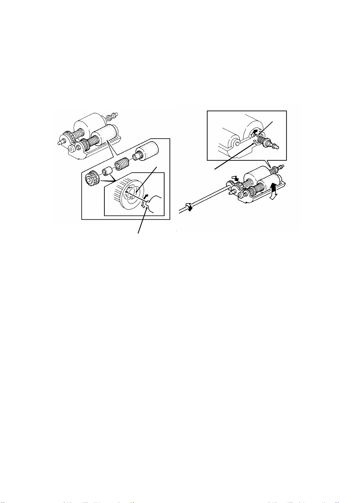
October 15th, 1991
3. Mechanical Clutch Mechanism
The following clutch gear mechanism is an attempt to minimize the amount of
time between pages without using extra electrical components and sensors.
In addition, this type of scanner does not require an electromagnetic ADF
clutch. Another feature of this type of scanner is that the R1 and R2 rollers rotate faster than the feed and pick-up rollers.
[C]
[B]
[D]
[A]
The pick-up and feed rollers both contain a mechanical clutch. The clutch
consists of two sleeves, one with a tab on it, and one with a notch in it (instead of a notch, there may be a ridge).
In the pick-up roller clutch (left hand drawing), the tab [A] is attached to the
roller and travels at the same speed as the roller. However, the notch sleeve
[B] is connected to the pick-up clutch drive gear, which is driven by the tx motor. (When the R1 and R2 rollers take the paper, they will pull the paper faster
than the speed of the drive from the pick-up clutch gear. At this time, the
roller will be pulled by the paper, and it will rotate faster.)
In the feed roller clutch (right hand drawing), the tab [C] is connected to the
spring clutch on the roller, which is rotated by the tx motor. The notch [D] is
directly attached to the feed roller bracket and cannot be moved.
Spring clutches inside the roller drive mechanisms allow each roller to rotate
in the paper feed direction even if the tab inside the roller is pushing against
the notch. The clutch in the pick-up roller controls the interval between
pages, and the clutch in the feed roller controls mechanism resetting after all
pages of the document have been scanned. See the following pages for a full
description of a typical mechanism.
2-2-8
Page 56

October 15th, 1991
- Pick-up Roller Clutch -
[A]
[B]
Figure 1
[C]
[D]
[E]
Figure 2
In standby mode (figure 1), the pick-up roller clutch tab [A] is positioned at
the mid point of the notch [B].
When the tx motor starts (figure 2), the pick-up roller sleeve moves in the paper feed direction. However, the pick-up roller [C] does not start to rotate until the notch sleeve contacts the tab. While the roller is stationary, the shutter
[D] lifts out of the paper feed path to allow a sheet of paper to be fed (see
"Shutter", section 2-1-1). See the next page for details on the feed roller [E].
[F]
[G]
Figure 4Figure 3
The pick-up roller feeds a page into the scanner (figure 3). When the leading
edge of the page reaches the R1 rollers [F], the page is pulled through the
scanner faster. The page pulls the feed and pick-up rollers, so that they now
rotate at the same speed as the R1 and R2 rollers. The pick-up roller is now
moving faster than the drive gear [G], so the tab moves across to the other
side of the notch, and pushes against the side of the notch.
When the trailing edge of the page leaves the pick-up roller (figure 4), the
roller is no longer being pulled at the same speed as the R1 and R2 rollers.
The tab stops moving until the other side of the notch, driven by the tx motor,
rotates across to contact it. While the notch sleeve is moving across, the pickup roller does not rotate. However, when the notch catches up with the tab
(figure 5, on the next page), the roller starts to rotate, and the next page is
fed into the scanner.
2-2-9
Page 57

October 15th, 1991
The gap between the first and second pages is determined by the time that
the roller stops. This time is very short. In fact, in some models, the tx motor
has to be slowed down when the trailing edge passes the scan line sensor. If
this is not done, the next page follows too quickly, and the sensor never turns
off, rendering document jam detection ineffective.
Figure 5
Figure 6
If no more pages remain in the feeder (figure 6), the tx motor reverses briefly
so that the shutter can come down and so that the pick-up clutch mechanism
returns to the standby position (same as in figure 1). The pin in the feed roller
clutch limits how far the tx motor can reverse the pick-up and feed rollers, so
the pin in the pick-up roller clutch can be positioned precisely.
- Feed Roller Clutch -
[B]
Figure 1[A]
Figure 2
In standby mode (figure 1), the tab [A] in the feed roller clutch is touching the
end of the notch [B]. When the tx motor starts (figure 2), the tab starts to
move, until it contacts the other side of the notch.
[C]
Figure 3
This continues until after the final
page has been scanned (figure 3).
At this time, the tx motor reverses
briefly. When the tab contacts the
other side of the notch, back at its
original position, gear [C] does not
move any more. In this way, the tab
in the pick-up clutch is positioned
accurately at the centre of its notch.
2-2-10
Page 58

October 15th, 1991
4. Electrical Components
Sensors
The scan line and trailing edge sensors are both photointerrupters, with actuators across the document feed path.
Clutches
The ADF and document feed-out clutches are usually electromagnetic
clutches. Electromagnetic clutches are more reliable and more compact than
solenoid mechanisms.
Tx Motor
The tx motor is a stepper motor.
Stepper Motors
Stepper motors are used because they allow the cpu to know the position of paper in the
scanner accurately. Note that there is no end-to-end synchronization between the stepper
motors in the communicating fax machines, and there is no relation between stepper
motor operation and I/O rate.
The accuracy of stepper motors means that they are preferentially used in scanner and
printer mechanisms in fax machines. However, they are not strong enough to drive laser
printer mechanisms, so brushless dc motors are used for this purpose.
For a discussion of different types of motor, see Appendix D.
Cross-references
Motors, photointerrupters, and clutches: Appendix D
2-2-11
Page 59

October 15th, 1991
5. Resolution
There are up to three resolution settings on the operation panel (the operation panel controller informs the cpu of the resolution selected by the user).
The settings are as follows.
Setting Sub-scan Resolution
Standard 3.85 lines/mm
Detail 7.7 lines/mm
Fine 15.4 lines/mm
The scanner mechanism operates differently for each of these resolutions.
However, the method used by each model is different, so a generalized description will be given here.
- Standard and Detail Resolution -
The page is scanned at 7.7 lines/mm.
In Detail mode, the data is transmitted as it is. However, in Standard mode,
transmission must take place at 3.85 lines/mm down the page. To change the
7.7 line/mm data into 3.85 line/mm data, the number of lines of scanned image data must be halved before transmission. There are two common ways
to do this.
• Skip alternate lines of data
• OR process consecutive lines
- Fine Resolution -
The page is scanned at 15.4 steps/mm.
However, in most machines, the data is converted to 7.7 lines/mm before
transmission. This conversion is made in a similar way to the conversion
made in Standard mode described above.
Fine resolution is reproduced at the other end if the receiving machine can
understand from the transmitted NSS signal that the message is in fine resolution, and if it can do detail resolution to fine resolution smoothing. If the receiving machine cannot print at fine resolution, it will print the message using
detail resolution.
Cross-references
Resolution: section 2-3-1
OR processing: section 2-3-4
Smoothing: sections 3-5-1 and 4-3-5
2-2-12
Page 60

October 15th, 1991
6. Document Jam Conditions
The cpu detects document jams by monitoring the sensors in the scanner
mechanism, and by keeping track of whether the amount of document fed so
far has exceeded the maximum document length limit.
Document jam detection timing conditions vary from model to model.
Note
The maximum document length can be adjusted by bit switch. The normal maximum is
0.6 m or 1.2 m. However, higher settings or unlimited length are often available. Long
documents have to be manually supported by the user.
The longer length settings are useful for those who have to send long documents such as
well logs (geological survey data from oil wells or other boreholes).
2-2-2. Separation Mechanism
ADF Clutch
Separation
Roller
Separation Pressure
Feed
Roller
Pick-up Roller
Plate
When a multi-page document is placed in the feeder, the separation pressure
plate spreads out the leading edges of the document. The pick-up roller
picks up the bottom sheet and feeds it to the feed roller, which feeds the
page into the scanner. The separation roller prevents more than one sheet of
paper from feeding into the scanner at once. The roller’s torque must be high
enough to prevent double feeds, such as those caused by the user inserting
a document into the feeder forcefully.
Springs compress the separation roller along the shaft, and force it downward towards the paper. (The spring mechanism differs from model to model,
so the springs are not shown here.)
2-2-13
Page 61

October 15th, 1991
A certain torque (F1) is required before the roller can move.
When the torque is less than F1 (see below), the separation roller resists mo-
tion in the paper feed direction. When torque on the separation roller exceeds F1, the separation roller rotates with the feed roller.
Separation
Roller
F1
Feed
Roller
F2
F2
F1
Separation
Roller
F1
Feed
Roller
F1F3
F3
F2
The direction that the separation roller turns depends on the friction forces
that act on it. When there is only one sheet of paper between the rollers, friction between the feed roller and the paper (F2) is greater than F1. So the
separation roller turns in the paper feed direction.
If two or more sheets are fed, the forward force on the second sheet (F3) is
less than F1 because friction between sheets of paper is low. So the force of
the springs is not overcome and the separation roller prevents the extra
sheets from entering the scanner.
Note
If there are double feed or non-feed problems, the separation roller torque and/or
pressure can be adjusted. The method varies from model to model, but the principles are
the same.
Double feed: Either increase the torque or reduce the pressure.
Non-feed: Either reduce the torque or increase the pressure.
Some models do not have these adjustments.
2-2-14
Page 62

2-2-3. Manual Feed
Separation
Roller
October 15th, 1991
Manual Feed Button
Feed
Roller
Pick-up Roller
When the manual feed button is pushed, the separation roller lifts away from
the feed roller, so that thicker pages than normal can be fed through the scanner. The user can transmit A2 [16.5" x 23.4"] originals using manual feed by
folding them in half and sending each half separately.
In some models, the line is disconnected after each page if manual feed is
used in this way. In other models, the user has a few seconds to feed the second half in after the first half has been fed out.
Manual Feed Switch
Separation
Roller
Manual Feed
Button
Manual Feed
Switch
Some models have a sensor, usually a microswitch, attached to the manual
feed mechanism. When the user presses the manual feed button, the separation roller assembly lifts up, and the microswitch, (known as the manual feed
switch) opens. After this, when the document sensor detects a document,
the tx motor turns on to feed the page part-way into the scanner, using the
R1 roller (this does not happen during automatic feed). Also, the display
panel informs the user that manual feed is in use.
2-2-15
Page 63

2-3. VIDEO PROCESSING
2-3-1. Outline
1. Principle
This section deals with the processing of scanner data from its generation by
the CCD until its output to the modem as eight-bit digital data.
After the user presses Start, document feed and scanning begin.
When a digital fax machine scans an original, it treats it as a matrix of black
and white dots. Each dot is known as a picture element (pel or pixel for
short).
2-3-1
Page 64

The size of the dots depends on the resolution selected by the user.
Standard Detail Fine Super-fine
Across the
page
Down the
page
8 dots/mm 8 dots/mm 8 dots/mm 16 dots/mm
3.85 dots/mm 7.7 dots/mm 15.4 dots/ mm 15.4 dots/ mm
In machines designed for Group 4 communication, the page is scanned on a
dot per inch (dpi) basis.
Standard Detail Fine Super-fine
Across the
page
Down the
page
200 dpi 200 dpi 200 dpi 400 dpi
200 dpi 200 dpi 400 dpi 400 dpi
2. Optic Path
Exposure Glass
Shading Plate
CCD
Lamp
Lens Block
Shading Plate
Profile
To convert a document into picture elements, the scanner must illuminate it,
and focus the reflected light onto a light-sensitive device. This device will convert the reflected image into an electrical signal, one line at a time.
A lamp (normally a fluorescent lamp or xenon lamp) illuminates the document
as it passes over the exposure glass. White areas on the original reflect light
from the lamp, and black areas absorb the light. The light reflected from the
document passes through a shading plate, which allows more light to pass
through from the ends of the lamp than from the centre; this corrects for the
relative dimness of the ends of the lamp. The lens block then focuses the image onto the light-sensitive device, which is normally a CCD (Charge Coupled Device).
2-3-2
Page 65

3. Scan Line
The CCD is a line of photosensitive elements. Light from one line across the
document is focused onto this line of elements.
This line across the document is called the ’main scan’ or the ’scan line’. The
width of the scan line depends on the resolution selected by the user, as follows.
Standard Detail Fine Super-fine
1/3.85 mm 1/7.7 mm 1/15.4 mm 1/15.4 mm
In machines designed for Group 4 communication, the page is scanned on a
dot per inch (dpi) basis.
Standard Detail Fine Super-fine
1/200 inch 1/200 inch 1/400 inch 1/400 inch
2-3-3
Page 66
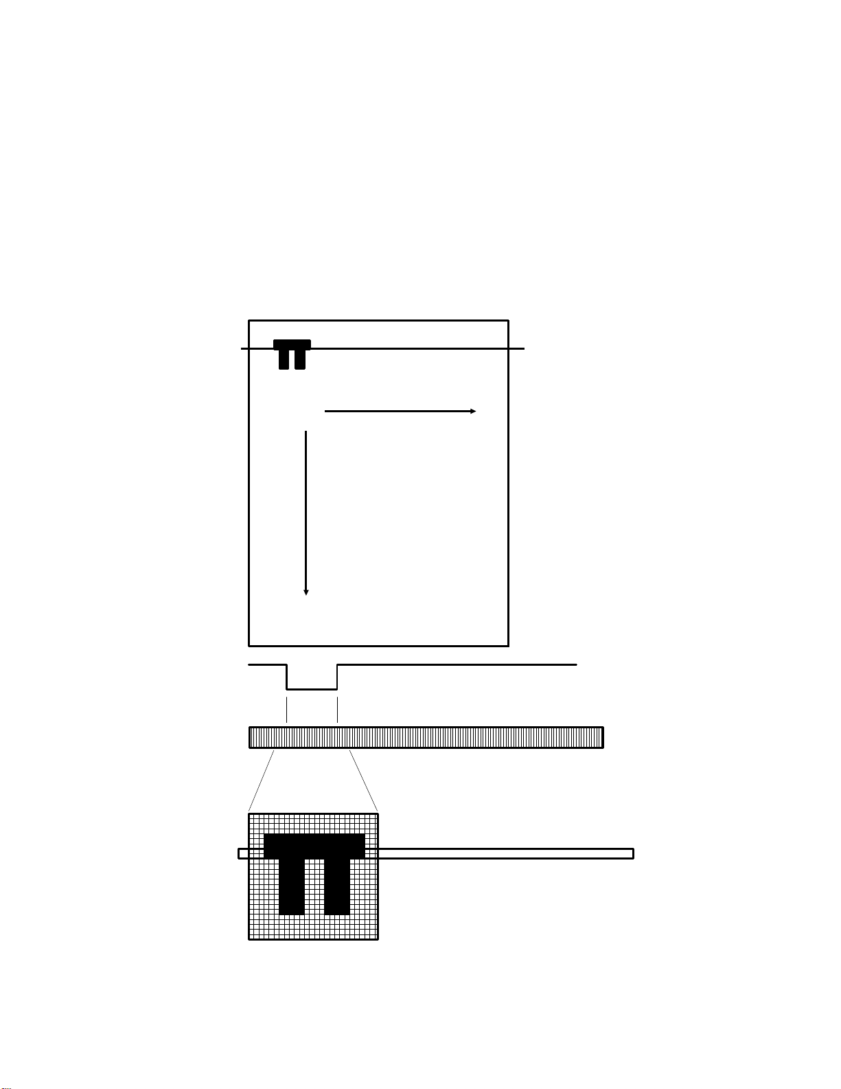
4. Scanning
Each element of the CCD scans one picture element on the line.
CCDs usually scan across the document at 8 dots per mm. CCDs used in
high-cost fax machines may scan at up to 16 dots per mm, and those used
in Group 4 based fax machines may scan at up to 400 dots per inch.
Each element of the CCD generates a voltage which represents the intensity
of the light reflected onto it from the document. The signals from all the elements are output in sequence, to generate an analog signal that represents
the line that is currently being scanned.
ORIGINAL
SCAN LINE
MAIN SCAN
CCD
Output
SUB
SCAN
White
Black
CCD
SCAN LINE
2-3-4
Page 67
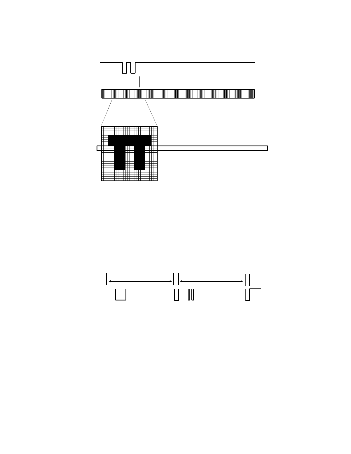
After one line has been scanned, the scanner moves the document forward
one scan line width to move the next scan line into position. Then, the CCD
reads the next scan line.
CCD
Output
White
Black
CCD
SCAN LINE
The movement of the document forward through the scanner is called the
’sub-scan’. The tx motor controls scanner movement very accurately.
The signals from each consecutive scan line are strung together end to end,
and sent out as an analog signal. The following diagram shows what the
video signal would be like for the two consecutive scan lines shown in the
previous two diagrams.
VIDEO SIGNAL
White
Black
One scan line
2-3-5
One scan line
Etc
Page 68

5. Signal Processing
Coupled Device)
CCD (Charge
SBU
Video
Processor
CPU
Modem
Memory
Line Buffer
FIFO
FCU
The signal is inverted and amplified before it passes to the video processor.
The video processor converts the CCD output from analog to digital, then
processes the digital data; some of the processes require a memory work
area.
After data processing, each element on the original is represented by one bit
(0: White, 1: Black), unless reduction was done (see section 2-3-7 for details
on reduction).
Then the cpu compresses the data and sends it to the SAF memory.
Contact Image Sensors
Some low-price compact models use a contact image sensor (CIS) instead of a CCD. A
CIS consists of a strip of phototransistors covered by a row of self focusing lenses. If a
CIS is used, the lenses, mirrors, and shading plate are not needed because the CIS
contacts the document directly, so the size of the scanner can be greatly reduced.
However, the built-in image processing circuits in CIS assemblies are inferior to the Video
Processors of mainstream fax machines.
Cross-references
Data circuit for various modes of transmission: section 1-3-1
CCD: Appendix D
2-3-6
Page 69

2-3-2. CCD Drive
The CCD (Charge Coupled Device) consists of a row of photosensitive elements. (Details about how a CCD works can be found in Appendix D.)
The CCD scans the original one line at a time, and outputs an analog signal
for each line. The analog signal is made up from the voltages generated by
the row of elements.
The voltage from each element depends on the intensity of the light reflected
from the original onto the element; the intensity of the light depends on the
darkness of the area of the document it was reflected from.
FCU
Video
Processor
E
XVIDEO
CPU
A
B C
Driver
CCD
+12V
+12V
0 V
+
Emitter
Follower
D
0 V
Inverter
Amplifier
SBU
The CCD output (also known as XVIDEO) is inverted and amplified before it
passes to the video processor. The emitter follower ensures that the impedance is low. In some models, there is a bias controller which automatically adjusts the black level voltage.
The cpu generates the CCD drive clocks [A - D]. The driver IC on the CCD
board drives the CCD using the clocks from the cpu.
In Group 4 terminals, the CCD may be 8 dots/mm or 16 dots/mm. However,
the optics of the scanner are laid out so that the image data is 200 dpi or 400
dpi in accordance with CCITT recommendations for Group 4.
2-3-7
Page 70
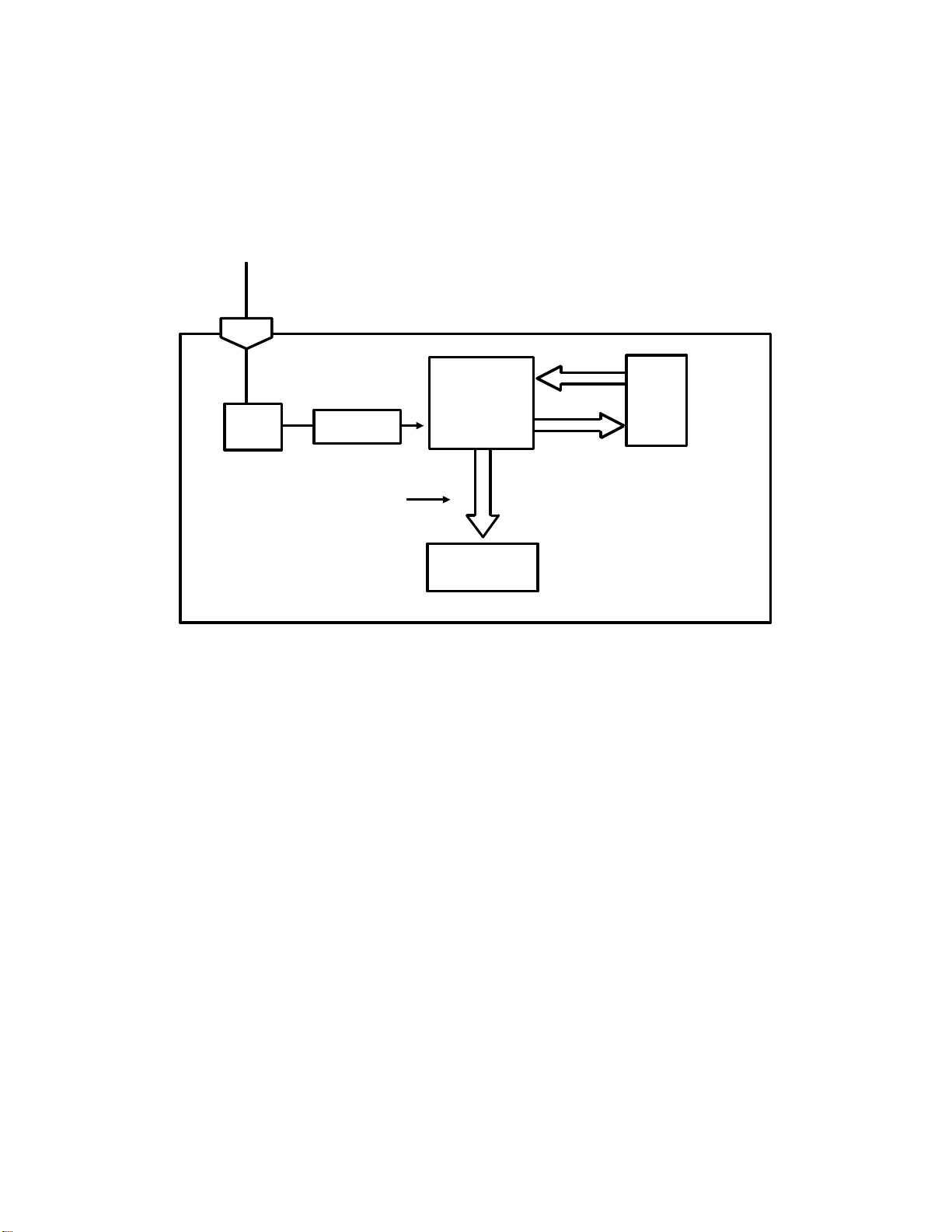
2-3-3. Data Correction
1. Overview
Video processing has two steps: auto shading, and scanning.
- Auto Shading -
Output
from
the CCD
A
FEEDBACK
Peak
Hold
VIDEO
PROCESSOR
DC
Filter
ONE SCAN LINE
(WHITE WAVEFORM)
Amplifier
A/D
Converter
Auto Shading
Memory
In auto shading, the machine scans a white strip opposite the exposure glass
to make a white waveform; this is done before each page is scanned.
The video signal from the CCD enters the Video Processor at pin A. First, the
dc filter removes the dc component of the CCD output. The resulting signal is
then amplified.
The output from each element of the CCD is converted to digital and passed
to the auto shading memory as a four-bit signal (in some models, this is an
eight-bit signal). The analog to digital (A/D) conversion is done using the
peak value of the signal as 0000 and the half-peak value as 1111. (The peak
value is taken using the peak hold circuit as explained later.)
Auto shading is necessary because of the following scanner irregularities:
• Irregularities in sensitivity between elements of the CCD
• Different effects on image brightness between the lens centre and pe-
riphery
• Differences in reflectivity across the length of the mirror
• Loss of brightness at the ends of fluorescent or xenon lamps with age,
or variations in brightness along the LED array
2-3-8
Page 71

- Scanning -
A
Output
from
the CCD
Auto Shading
Memory
WHITE
WAVEFORM
FEEDBACK
Peak
Hold
DATA
DC
Filter
VIDEO
PROCESSOR
A/D
Converter
Amplifier
CORRECTED
Data Processing
Circuits
To the CPU
and Modem
After auto shading, the machine scans the page of data.
Data from the document pass through the dc filter and amplifier in the same
way as for auto shading. The machine then uses the white waveform to correct the data for scanner irregularities.
The data is then processed (as described in section 2-3-4) and sent to the
cpu, which compresses the data and sends it to the SAF memory.
2-3-9
Page 72

2. DC Filtering and Amplification
0 V
DC FILTERED AMPLIFIED
The dc filter in the Video Processor removes the dc component of XVIDEO.
The resulting signal is then amplified.
The next step depends on whether the machine is doing auto shading (scanning the white plate opposite the exposure glass) or scanning the document.
3. Auto Shading and A/D Conversion
Half Peak Level (Black)
Example
Element
Peak Level (White)
Half Peak Level (1111)
All-white Waveform Element
(Becomes 0100)
Peak Level (0000)
Before scanning each page, auto shading is done. The machine reads an allwhite waveform from the white plate that is attached to the document guide,
directly opposite the exposure glass. The output from each element of the
CCD is converted to digital and passed to the auto shading memory as a
four-bit signal. The A/D conversion is done using the peak value of the signal
as 0000 and the half-peak value as 1111.
During scanning, the Video Processor A/D converts (converts from analog to
digital) the video signal one scan line at a time, using the peak hold value at
the time of scanning the scan line as 0000 (100% white) and black as 1111.
Each element of the analog video scan line becomes a four-bit digital signal.
At the same time, the scanned data is corrected for scanner irregularities as
outlined on the next page.
Note: The above diagram shows conversion to a 4-bit digital signal. Some
machines use an 8-bit digital signal.
2-3-10
Page 73

4. Peak Hold
Peak hold is done to correct for variation in background density down the
page. If there is no correction for this, background may be transmitted with
the data, making it difficult to read.
The peak hold circuit holds the maximum voltage encountered while scanning the page. If a higher voltage is found further down the page, this voltage
will replace the voltage currently held in the peak hold circuit. The peak hold
voltage is reset at the start of each new page.
The peak hold circuit only takes data from the central part of each scan line.
This is to avoid readings from the white plate when scanning a narrow original.
The peak value is converted from analog to digital and held in a register. If
the voltage from the CCD is higher than the previous peak, the new maximum is converted to digital and stored in the register. Otherwise, the register
value is unchanged until it is reset at the start of a new page.
5. Correction for Scanner Irregularities
When the document is scanned, the white waveform is read back in from the
auto shading memory. The comparator in the auto shading circuit uses the
white level signal to correct the video data signal. In effect, each element of
the scan line is amplified by an amount that depends on the voltage of the
same element in the white level signal.
Example:
Element 500
1
0.8
0
500
White Waveform
Scan Line
0.6
500
0
Video Image
Scan Line
Assume that the white level peak value is 1, and that the level of the 500th element of the white waveform is 0.8 (i.e., not perfectly white). Element 500 in
the video signal has a value of 0.6; it would be higher if there were no scanner irregularities. So, element 500 in the video signal is corrected as follows:
0.6/0.8 = 0.75. Each element in each video signal scan line is corrected in
this way. The corrected scan line is passed to the peak hold circuit.
2-3-11
Page 74
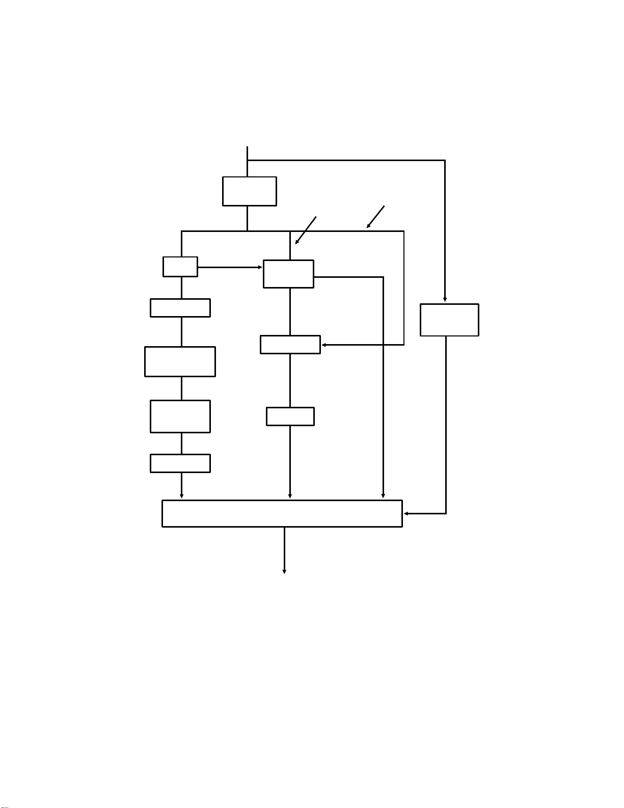
2-3-4. Digital Data Processing Steps
1. Overview
Corrected Data
from the
Auto Shading Circuit
MTF
Comparator
Background
Detection
OR
Processing
Reduction
A
Gamma
Correction
See Note 1.
Edge
Detection
NON-EDGE
ELEMENTS
Reduction
Halftone
B
Basic
Halftone
Process
EDGE
ELEMENTS
Error
Diffusion
Halftone
Process
Image/Text
Detection
B’
Process Selector
To CPU and Modem
The corrected data from the auto shading circuit must be converted to onebit data (0: White, 1: Black) before it can be sent to the cpu and modem.
The machine is equipped with processes such as halftone and MTF to make
sure that the one-bit signal represents the original as closely as possible. The
above diagram shows the flow of data through the various processes. Each
process is outlined in the following pages.
2-3-12
Page 75

There are two basic processes: MTF (left side of the diagram) and edge detection/halftone (centre of the diagram). Each picture element undergoes
both processes at the same time. Each process produces two results for the
same picture element (A and B, or A and B’). If the basic halftone process is
being used, B is generated if the element is not on the edge of a white or
black area, and B’ is generated if the element is on an edge.
The output of the image/text detector determines which result to send on to
the cpu. If the element is in a block of text, the output of the MTF process (A)
is selected. If the element is in a photograph, the output of the edge detection/halftone process (B or B’) is selected.
MTF, halftone, and the other processes treat each picture element in the image in relation to the picture elements adjacent to it. For example, each video
data element (X) is processed in relation to adjacent bits (a, b, c, and d in the
following diagram); reproduction of the original is more accurate than if the
adjacent bits are not used.
a
b X c
d
Line just processed
Line now being processed
Line to be processed next
Notes
1. If halftone is used, MTF and halftone will both be carried out on the data.
Outputs A and B (or A and B’) will be generated, and the Image/Text Detector has to select for each picture element which output goes forward
to the modem.
2. If MTF is switched off, the data will pass through the MTF circuit unchanged.
3. Not all models use OR processing to generate Standard mode data (see
section 2-2-1, "Resolution"). Some models skip alternate lines of data instead.
2-3-13
Page 76

2. Gamma Correction
Voltage
Shade
White
Black
Voltage
Shade
White
Black
This corrects the response of the CCD to the various shades in the gray
scale from black to white. For digital processing techniques to be most effective, the relationship between document contrast to CCD output voltage
should be constant, as shown in the diagram on the left. However, in reality,
the response is more like that shown in the diagram on the right. Gamma correction corrects the data for this deviation in CCD response.
3. MTF
MTF (Modulation Transfer Function) is necessary for transmission of details
such as thin lines, points, and complex characters. Without MTF, such details
may be lost, or only partly reproduced.
The MTF algorithm generates a new value for the density of the element, using an algorithm that uses the density values of neighboring elements in the
matrix register. The new density value for the element passes to the comparator for thresholding.
Note
MTF can usually be switched on/off by bit switch or RAM address adjustment.
2-3-14
Page 77

4. Thresholding
Black
1111
Four-bit Video
Signal
Threshold
White
0000
Black
1
White
0
One-bit Video
Signal
If halftone was not selected, each video data element is compared against
the threshold level, which depends on the contrast selected by the user. The
four-bit threshold level is stored in the system RAM, and is fed to a comparator, where thresholding is done.
If an element is lighter than the threshold level, it is converted to a 0 (white).
Otherwise, it becomes a 1 (black).
Note
There are RAM addresses for the threshold level for each of the contrast settings.
5. Background Detection
Background detection eliminates background markings, which are often reproduced by MTF. Each picture element is tested against the elements surrounding it to find out whether it is part of the background.
If an element is found to be background, it is corrected so that the background does not show up in the transmitted image. For example, if a black
dot is surrounded by nine white dots, it will be changed to a white dot.
If an element is found to be not background, it passes to the OR processing
circuit unchanged.
Note
Background detection can be switched on/off by bit switch or RAM address adjustment in
some models.
2-3-15
Page 78

6. OR Processing
The user may have selected a resolution that is less than the resolution used
by the scanner. If so, the machine will either do OR processing or skip alternate lines of data to convert the scanned resolution into the resolution required for transmission.
For example, assume that the thickness of a scanned line is 1/7.7 mm. However, for standard resolution it should be 1/3.85 mm. If the user selected
standard resolution for transmission, two consecutive lines are OR processed to make one line. (To reproduce standard resolution, the receiving terminal will print the line twice if it works at double the resolution.)
A similar principle can be applied for transmission at fine resolution, where
the 15.4 line/mm image is OR processed to 7.7 lines/mm.
The first two lines of a page are OR processed as shown below.
Line 1
Line 2
Result
Subsequent lines are processed in groups of two as follows.
A
B
C
D
A = The result of OR processing the previous two lines
B, C = The two lines now being OR processed
OR processing ensures that the resulting single line accurately reflects the
two consecutive lines that it is replacing.
Cross-reference
Scanner resolution: section 2-2-1, "Resolution"
2-3-16
Page 79

7. Reduction
Reduction is only done in machines with a document feeder that is B4-width
[10.1"] or wider.
Reduction is done if the paper at the other end is not wide enough to print
the message. The machine determines whether reduction is necessary by
comparing the received protocol signal with the document width sensor readings.
Main Scan Reduction
The machine does main scan reduction by systematically deleting elements
as follows.
Example: A3 to A4 reduction
[A] [B]
Cut
Out
Cut
Out
Cut
Out
Cut
Out
Cut
Out
Not
Cut
Out
Cut
Out
Instead
A3 [11.7"] to A4 [8.3"]: Data are treated in seven-element groups; every 3rd
and 7th element are deleted to achieve 5/7 reduction (see diagram).
A3 [11.7"] to B4 [10.1"]: Data are treated in eleven-element groups; every 7th
and 13th element are deleted to achieve 11/13 reduction.
B4 [10.1"] to A4 [8.3"]: Same as for A3 to B4.
There is one exception to this rule. If the element scheduled for deletion (A in
the above diagram) is darker than the element after it (B), (B) is deleted instead.
Cross-reference
Reduction: section 2-1-1 ("Document Detection Mechanism")
2-3-17
Page 80

Sub-Scan Reduction
Sub-scan reduction is reduction of data down the page.
The cpu does sub-scan reduction by cutting out the 3rd and 7th scan lines in
every 7 scan lines (for A3 [11.7" x 16.5"] to A4 [8.3" x 11.7"]) or the 6th and
13th scan lines in every 13 scan lines (for A3 [11.7" x 16.5"] to B4 [10.1" x
14.3"] and B4 [10.1" x 14.3"] to A4 [8.3" x 11.7"]).
Example: A3 to A4 reduction
1
2
3
4
5
6
7
1
2
3
4
5
6
1
2
3
4
5
Deleted
Deleted
Deleted
Deleted
7
Deleted
6
Deleted
7
1
2
4
5
6
1
2
4
5
6
1
2
4
5
6
Note
The reduction circuit is also capable of line/mm to dpi conversion, and dpi to line/mm
conversion. These features are necessary in models that are able to communicate both
on Group 3 and on Group 4 networks.
2-3-18
Page 81
8. Edge Detection
This process preserves the sharpness of image outlines. Each element is
tested to determine whether it is on a boundary of two areas of sharp contrast (such as the edge of a character on a white background). If the element
is on a boundary, it goes straight to the cpu as a black (1) element. (Halftone
processing on this element could lead to a fuzzy outline.)
Notes
Edge detection uses a threshold, which can be adjusted by RAM address in some models
if edges of characters appear fuzzy.
In some models, edge detection can be switched on/off by a RAM address adjustment.
9. Halftone
Basic Halftone Process
Each video signal element is converted from a four bit value (0 to 15) to a sixbit value (0 to 63) by an algorithm which uses the density of that element and
the densities of adjacent elements in the image. The six-bit value is sent to a
comparator.
In the comparator, each six-bit video data element is compared with the corresponding element in a dither matrix. The dither matrix is a 64-element matrix
of six-bit values.
If the value of the video data element is lower than the dither matrix element,
the data element becomes 0 (white). Otherwise, it becomes black (1). A simple example is given below.
Six-bit Video Dither Matrix Result
36 35 33 32 60 32 56 24 0 1 0 1
34 32 36 29 12 48 4 40 1 0 1 0
30 28 27 26 52 20 60 28 0 1 0 0
33 32 31 29 8 36 16 44 1 0 1 0
2-3-19
Page 82

The dither matrix shown on the previous page is only a typical example. The
actual matrix used varies from model to model, but they are usually either spiral or random matrixes. Matrixes with a spiral pattern are being increasingly
used. An example of each type is shown below for reference.
Spiral Matrix Random Matrix
62 58 54 50 60 32 56 24
18 14 10 46 12 48 4 40
22 2 6 42 52 20 60 28
26 30 34 38 8 36 16 44
Error Diffusion Halftone Process
Another type of halftone process is also available, in which the each element
is corrected using the differences between it and the surrounding elements.
The corrected elements are then compared with a dither matrix in a similar
way as for the Basic Halftone Process described above.
The Error Diffusion process reduces the difference in contrast between light
and dark areas of a halftone image. However, it increases the time required
for communication; this is because the image is more complex and more difficult to compress efficiently (often, the compressed data is longer than the
original data, so the original data has to be sent).
Note
The default halftone mode (basic process or error diffusion process) can be selected by a
RAM address adjustment.
There may be more than one dither matrix type available with each machine. The dither
matrix can be selected by a RAM address adjustment.
Halftone mode requires more processing, so scanning is slower. Also, image
data generated using halftone mode cannot be compressed so much as
other image data, so transmission will take longer, especially for the Error Diffusion process. See Appendix E for more about compression.
2-3-20
Page 83

10. Image/Text Detection and Process Selection
If halftone is selected, each element is tested against surrounding elements
to determine whether it is part of a block of text or part of a complex image
such as a photograph or a diagram containing various types of shading. The
result of the test is fed to the process selector.
If the element is found to be part of a block of text, the process selector selects the output of the MTF/background detection process, and discards the
output of the edge detection/halftone circuit.
If the element is found to be part of a complex image, the process selector
selects the output of the edge detection/halftone circuit, and discards the output of the MTF/background detection process.
To decide which process to select for an element, a threshold value is compared with an algorithm of the densities of the element being tested and the
surrounding elements.
Notes
In some models, the process selection threshold value can be changed by RAM address
adjustment. Experiment with this if reproduction of documents with photographs in
halftone mode is unsatisfactory.
11. Storage in SAF Memory
The output of the process selector is sent to the cpu. The cpu stores the data
in the SAF memory until the machine has successfully contacted the terminal
at the other end.
In some models, the data is compressed before storing. This is to conserve
memory space. If a line of data, when compressed, is longer than the original
line, the line is stored as uncoded data. This may often happen when halftone mode is being used.
At the time of transmission, the data comes out of the SAF memory. Further
processing is done before the data is transmitted. See section 2-8 for details.
2-3-21
Page 84

2-4. CALL COLLISION PREVENTION
2-4-1. Overview
After placing a document in the feeder, the user enters the telephone number
at the operation panel’s ten-key pad, then presses the Start key. The machine then scans the document and stores it in the SAF memory. The machine then prepares to dial.
Note: Remember that for transmission that does not use the memory, the
order of events is different. After the user presses Start, the document is fed partway into the scanner and the machine dials. Scanning and storing is done after the other end has been reached. See
section 2-10-2 for details.
However, before the machine dials, it must check whether another call is in
progress or not, to prevent a collision of incoming and outgoing signals. If
the machine detects that a call is already in progress, it will wait until the line
is clear before dialling.
There are two criteria for detecting whether a call is in progress.
1. Has a ringing signal been detected, or is a potential ringing signal still being analysed?
2. Is the local loop with the local telephone exchange closed?
To understand this, we need to understand how a fax machine connects to a
PSTN (Public Switched Telephone Network). This explanation begins on the
next page. The explanation is based on network conditions in the USA; details differ from country to country.
2-4-1
Page 85

2-4-2. PSTN Circuit
1. DC Loop - Overview
Every telephone or fax machine is connected to a local exchange of the
PSTN through a two-wire pair. One wire is called "Tip" and the other is called
"Ring"; these names refer to the tip and ring parts of the plugs used in manual switchboards (in Europe, L1 and L2 are often preferred). This two-wire circuit is known as the "dc loop", or "local loop".
Each telephone and fax machine contains a switch which opens and closes
the local loop. When the switch is closed, dc generated by the local exchange flows through the dc loop. The voltage on the dc loop varies from
area to area; for example, in the USA, it is about 48 V.
Fax or Telephone
Fax or Telephone
LOOP OPEN
Local Exchange
+
Local Exchange
LOOP CLOSED
+
2-4-2
Page 86

2. DC Loop through Telephone
Ringing
Signal
Generator
(20-47 Hz)
TELEPHONE (Simplified)
Dialing
Circuit
Hook
Switch
LOCAL EXCHANGE
Ringer
+
RING
TIP
When the telephone is on-hook, the hook switch connecting it to the local exchange is open, and dc from the local exchange cannot pass through the dc
loop. However, the telephone’s ringer is connected (the ringer does not allow
the dc from the exchange to pass, but allows the ac ringing signal to pass).
When the handset is picked up, pressure on the hook switch is released, and
the switch closes. Then, dc from the local exchange passes through the dc
loop.
2-4-3
Page 87

3. DC Loop through Fax Machine with External Telephone
To/From Fax Circuits
Line
Ds Relay
+24V
Current
Detector
Handset
Hook Switch
Oh Relay
FAX TERMINAL
(Simplified)
LOCAL EXCHANGE
Ringing
Signal
Generator
(20-47 Hz)
Ringing
Signal
Detector
+
Inside the fax machine, there are two components, called the Oh relay and
the Ds relay. These act as the fax machine’s hook switch.
When the machine is in standby mode (as shown above), the Oh relay is set
up so that the network is connected to the external telephone (commonly
known as the handset); in this set-up, the handset can be used as a normal
telephone, as explained on the previous page. The dc loop is open, because
the handset’s hook switch is open. However, the ringing signal detector in
the fax machine and the ringer in the handset are both connected to the line.
When the machine closes the dc loop, it switches over the Oh relay to disconnect the handset from the line. Then it closes the Ds relay to connect the fax
machine to the dc loop. The fax machine’s cpu will be able to detect the presence of dc by monitoring the line current detector.
2-4-4
Page 88

Note: In France, the Di switch is in series with the Oh relay instead of the
Ds relay, and the Di relay closes the dc loop.
2-4-3. Call Collision Prevention in Fax Machines
For 0.2 s after the user presses Start, the cpu monitors the ringing signal detector and the line current detector to check that the local loop has not already been closed (if the local loop has been closed, there will be current on
the telephone line). If a possible ringing signal is still being analyzed when the
user presses Start, the cpu will wait for 8 s, then check whether the signal is
still being analyzed.
The call collision prevention circuit is shown below. The circuit shown is for a
fax machine in standby mode.
L1
Network
L2
Line
Current
Sensor
T1
Handset
T2
LINE CURRENT
LINE CURRENT
CPU
RINGING SIGNAL
Ringing signal detector: This circuit consists of some zener diodes and a
photocoupler. It is adjustable, to allow for variations in ringing signals within
Europe. If the voltage of an incoming signal is high enough, it turns on the
photocoupler. Then, the cpu detects that its connection to the ringing signal
detector has been grounded.
Line current detector: This is a Hall effect sensor. The cpu detects line current when one of the sensor outputs is grounded; the output that is
grounded depends on the polarity of the dc on the loop.
Cross-references
Line current detection: section 2-5-2 Ringing signal detection: section 3-1
Dc loop closure: section 2-5-1 Document feed mechanism: section 2-2
Hall effect: Appendix D
2-4-5
Page 89

2-5. DC LOOP CLOSURE AND LINE MONITORING
After it has been confirmed that there is no possibility of call collision, the machine automatically closes the circuit between itself and the local exchange;
this circuit is commonly called the dc loop, or the local loop. Closing the dc
loop is the fax machine’s way of going off-hook before dialling.
In some areas, dialling cannot begin until the machine has checked for dial
tone and line current. This is known as "line monitoring".
2-5-1. DC Loop Closure
The fax machine closes the dc loop after checking for incoming calls. If there
is no incoming call, the cpu closes the dc loop by activating the Oh relay to
disconnect the handset from the line. Then, after 5 ms, it closes the Ds relay
to connect the fax machine to the line.
OH
Relay
Ds or Di
Relay
[A]
5 ms
Dialling
Only if pulse dialing
starts
is used
The cpu then waits for the ’PSTN wait interval’ [A] of about 2 s before starting
to dial.
Note
PSTN wait interval: This can normally be adjusted by RAM address.
On the circuit diagrams following, curved arrows show the relays switching
over from standby mode to close the dc loop.
2-5-1
Page 90
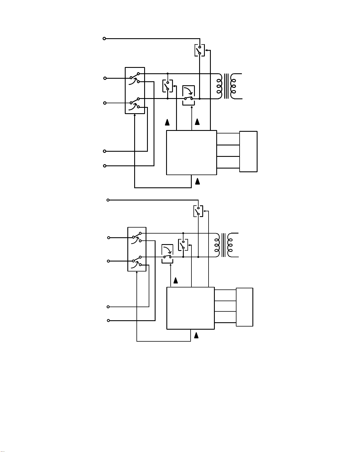
GS
Line
OH
Gs
Di
Ds
Handset
GS
Line
OH
Driver
Gs
5
OH
Di
Ds
CPU
Gs
5
OH
5
Ds
Di
5
Di
Ds
Handset
Driver
5
CPU
Gs
In most countries, the circuit is as shown in the top diagram (the Ds relay
closes the dc loop). In France, the circuit is as shown in the bottom diagram
(the Di relay closes the dc loop). The Gs relay is not used for dc loop closure; it is only shown for reference in these diagrams.
2-5-2
Page 91
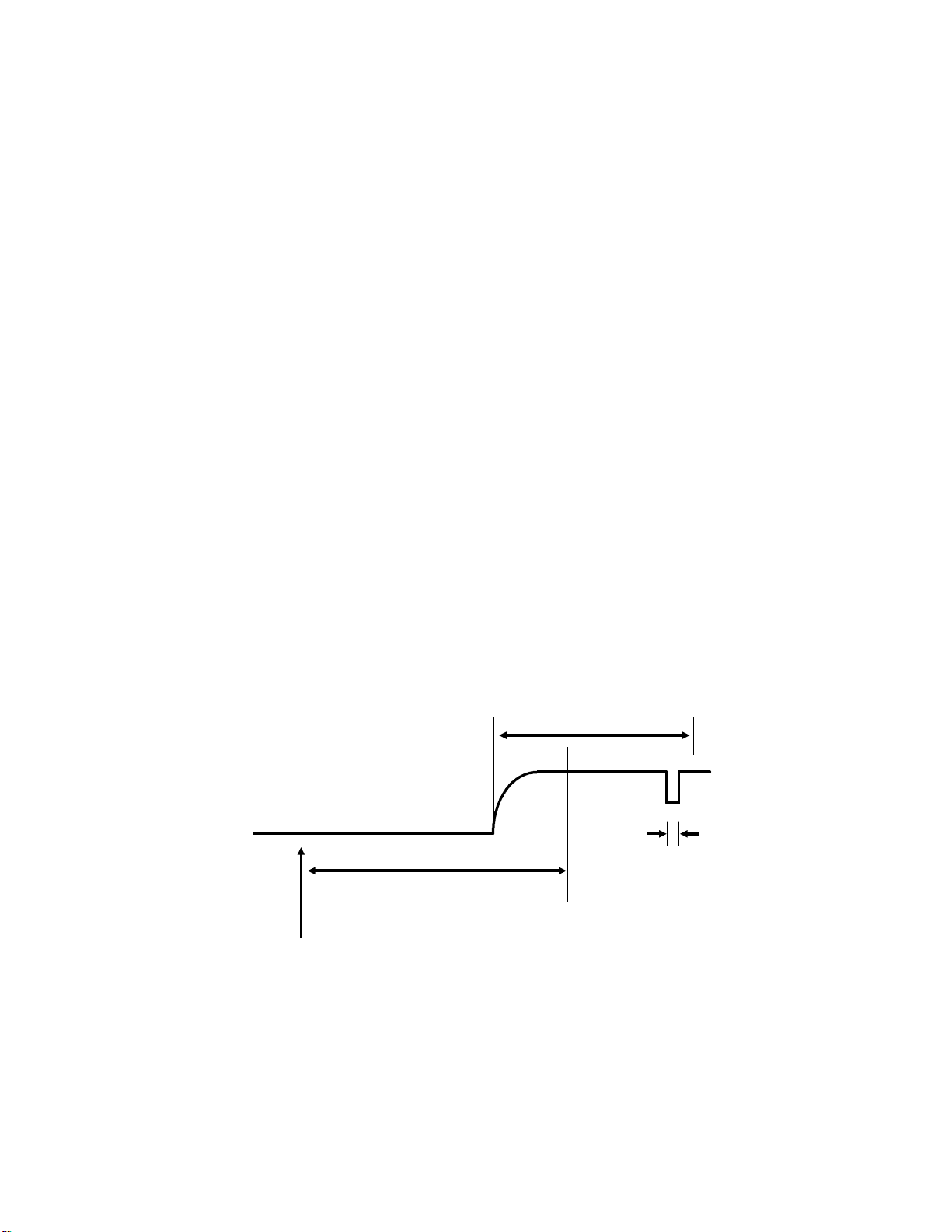
2-5-2. Line Monitoring
Before starting to dial, conditions in parts of Europe require that the machine
monitors the line current detector for line current, and signals on the line for
dial tone.
Therefore, in Europe/Asia models, the PSTN wait interval can be replaced by
dial tone and line current detection, if required by local conditions. (Dial tone
and line current detection are also available in USA versions of some of the
more complex models.)
1. Line Current Monitoring
Line current detection allows the machine to check whether the dc loop has
been closed. If there is no line current, the dc loop may still be open.
The machine uses the following parameters to detect line current.
• Line current wait time (A)
• Line current detection time (B)
• Line current drop detection time (C)
A starts when the dc loop closes. B starts when the line current first reaches
the machine.
The machine checks for line current during A. Line current must be on the
line for B or longer before it is recognized by the cpu. If the cpu has not recognized line current during the interval A, the machine disconnects. However,
if the line current has started but has not been on for B when A expires (as
shown below), detection continues until it has been on for B.
[B]
[C]
[A]
Line Current Monitoring
Starts Here
After starting B, the machine continually checks the line current for interruptions. If any single interruption lasts for C or longer, the line is cut, A and B
are reset, and the machine returns to standby.
2-5-3
Page 92

2. Dial Tone Monitoring
The local exchange sends a dial tone to inform the user that the exchange
can accept a telephone number. Dial tone monitoring allows the fax machine
to check for this tone before dialling; if there is no dial tone, the exchange
may not be ready to accept a telephone number.
The machine uses the following parameters to detect dial tone.
• Acceptable frequency range
• Dial tone detection time (A)
• Reset time (B)
• Continuous tone time (C)
• Permissible drop time (D)
B starts when the dc loop is closed. Dial tone must appear before B expires.
If dial tone appears just as B expires, detection continues and the deadline at
the end of B is ignored.
The machine detects a dial tone when the tone continues for C or longer without interruption. Also, A must have passed since the dial tone first appeared.
Interruptions shorter than D are ignored.
Dial tone
first appears
Dial Tone
DC Loop
Closure
<[C]
[A]
[C]
>=[D]
<[D]
Dial Tone
Detected
[B]
2-5-4
Page 93

3. Switching Line Monitoring On/Off
A nation that requires line monitoring has the necessary parameters programmed in the ROM; they are normally activated when the country code
(normally a bit switch setting) is set to the code for that nation.
However, if required, line current and dial tone can be disabled; the way to do
this varies from model to model.
Similarly, in countries which normally have line monitoring disabled, line current and dial tone detection can be enabled; however, the parameters for detection will have to be stored in the appropriate RAM addresses.
Dial Pulses or Tones
[A]
Loop
Closure
When line monitoring is disabled, the machine waits for the PSTN wait interval [A] before starting to dial.
Note
The following parameters can be programmed by RAM address.
Line Current Monitoring
Line current wait time Line current detection time
Line current drop detection time Line current monitoring on/off
Dial Tone Monitoring
Acceptable frequency range Dial tone detection time
Reset time Continuous tone time
Permissible drop time Dial tone monitoring on/off
Other
PSTN wait interval
Cross-references
Dc loop: section 2-4
Line current: section 2-4
2-5-5
Page 94

2-6. DIALLING
After the dc loop has been closed, the machine can dial. In automatic dialling
mode, the machine dials in accordance with the number entered by the user
at the operation panel, either in full, or as a Quick Dial or Speed Dial.
There are two types of dialling: pulse dialling, and tone dialling. The dialling
method must match the dialling mode that can be accepted by the local exchange, or the machine will not be able to dial out.
The dialling method can be chosen by a user function in most countries.
2-6-1. Pulse Dialling
Pulse dialling was originally developed to operate mechanical switching systems in the local exchanges.
The machine sends voltage pulses to the local exchange by interrupting the
dc loop. It does this by opening and closing the Di switch. Each digit is represented as a different number of pulses. For example, to dial a "2", the machine sends out 2 pulses.
The Oh relay remains fixed during dialling (it does not move until the machine
returns to standby mode). The Di switch is a relay. This is because of PTT requirements in some areas.
When the Di relay is opened and closed, there are sharp voltage peaks at the
leading and trailing edges of the dial pulses, which could damage circuits in
the machine. Because of this, a extra relay is added to the dialling circuit; this
relay is known as the Ds relay. The Ds relay is opened while the Di relay is dialling, to prevent voltage spikes from damaging the machine.
To the modem
and other data
circuits
Di
Line
OH
Di
Ds
5
5
Handset
2-6-1
Driver
Ds
CPU
Page 95

Each digit of the telephone number is sent out as a pulse train. The cpu
sends out the dial pulses by switching the Di and Ds relays in accordance
with the following timing.
Example: Dialling 32
[C]
Ds
[B] [B] [B]
Di
[D] [A]
[A] [A] [A] [A]
[D][E]
[E]
3 2
The time that the Di relay opens is called the break time [A] and the time that
it closes is called the make time [B]. Each pulse sent out on the line is made
by opening and closing the Di relay.
A minimum pause [C] is required between each digit, regardless of whether
the user pressed the pause key while dialling.
Notes
Most countries dial in the same way (the number of pulses sent out [P] is the same as the
number dialled [N]). However, some areas require different types of pulse dial signals. For
example, in Oslo, P must be 10 - N, and in Sweden, P must be N + 1. The required
mode can be selected by bit switch adjustment.
Pulse dialling can be done at two rates: 10 pulses per second (pps) or 20 pps. If the local
exchange can only handle 10 pps dialling, the machine must not be set to dial at 20 pps.
The dial pulse rate can usually be adjusted by bit switch.
Parameters A to E illustrated on the diagrams in this section are programmable.
For pulse dialling at 10 pps, the times stored in the NCU parameters are used as
explained in this section. However, at 20 pps, only half the values in parameters A, B, D,
and E are used, and three-quarters of the value in parameter C.
2-6-2
Page 96

In France, the relay circuit and the relay timing are different, as already mentioned in sections 2-4-2 and 2-5-1. The principle is the same, however.
To the modem
and other data
OH
Ds
Line
Di
55
circuits
Di
Handset
Ds
Di
[D] [A]
Driver
[C]
[B] [B] [B]
[A] [A] [A] [A]
[E] [D]
Ds
[E]
CPU
3 2
2-6-3
Page 97

2-6-2. Tone Dialling
Each dialled digit is sent out as a DTMF (Dual Tone Multi Frequency) tone,
which is a mixture of two frequencies. The following diagram shows what frequencies are generated for each digit on a typical telephone keypad. For example, a ’5’ is represented by a 770 Hz tone combined with a 1,336 Hz tone.
1209 1366 1477
697
770
852
941
2 31
5 64
8 97
0 #*
The DTMF tone frequencies are the same throughout the world. They were
carefully chosen so as not to coincide with other frequencies that may occur
on the line.
In some types of telephone equipment, the DTMF circuit remains on line after
the call has been connected. This allows the use of DTMF tones for giving orders to the remote terminal (e.g., extracting information from a remote database).
The advantages of using DTMF over pulse dialling are as follows.
• Dialling is faster
• DTMF tone generation circuits are compact solid-state circuits
• There can be end-to-end signalling after call connection, as mentioned
in the previous paragraph
Exchangers that use DTMF dialling are becoming more widespread.
2-6-4
Page 98

The following diagram shows how DTMF tones are generated in fax machines.
To the
Network
Filter
Adder
Filter
CPU
Attenuator
The cpu generates two square waves of the required frequencies. These
each pass through a low pass filter to remove noise, and are added together.
In the attenuator, the DTMF tone is attenuated. The attenuation value is different from that used for the attenuation of facsimile data.
The DTMF tone is then amplified to compensate for the signal loss between
the attenuator and the telephone line. The tone then passes to the line
through the Ds or Di relay and the Oh relay, which remain fixed during tone
dialling.
2-6-5
Page 99

- Attenuation of DTMF Tones -
A variable resistor can be used to adjust the signal level within a range of
about 2 dB.
Note
The DTMF tone attenuation value can be adjusted by RAM address. However, unlike the
attenuation value for facsimile data, it cannot be adjusted using dedicated transmission
parameters or bit switches.
- Timing -
DTMF tones are sent out in accordance with the following timing.
[A] [B]
Note
The DTMF tone on time [A] and off time [B] can be adjusted by RAM address.
2-6-3. Pauses
If the user dials a pause using the Pause key
, the machine waits for a pre-programmed interval before sending the next
tone or pulse.
Note
The pause interval can be changed using a RAM address adjustment.
2-6-6
Page 100
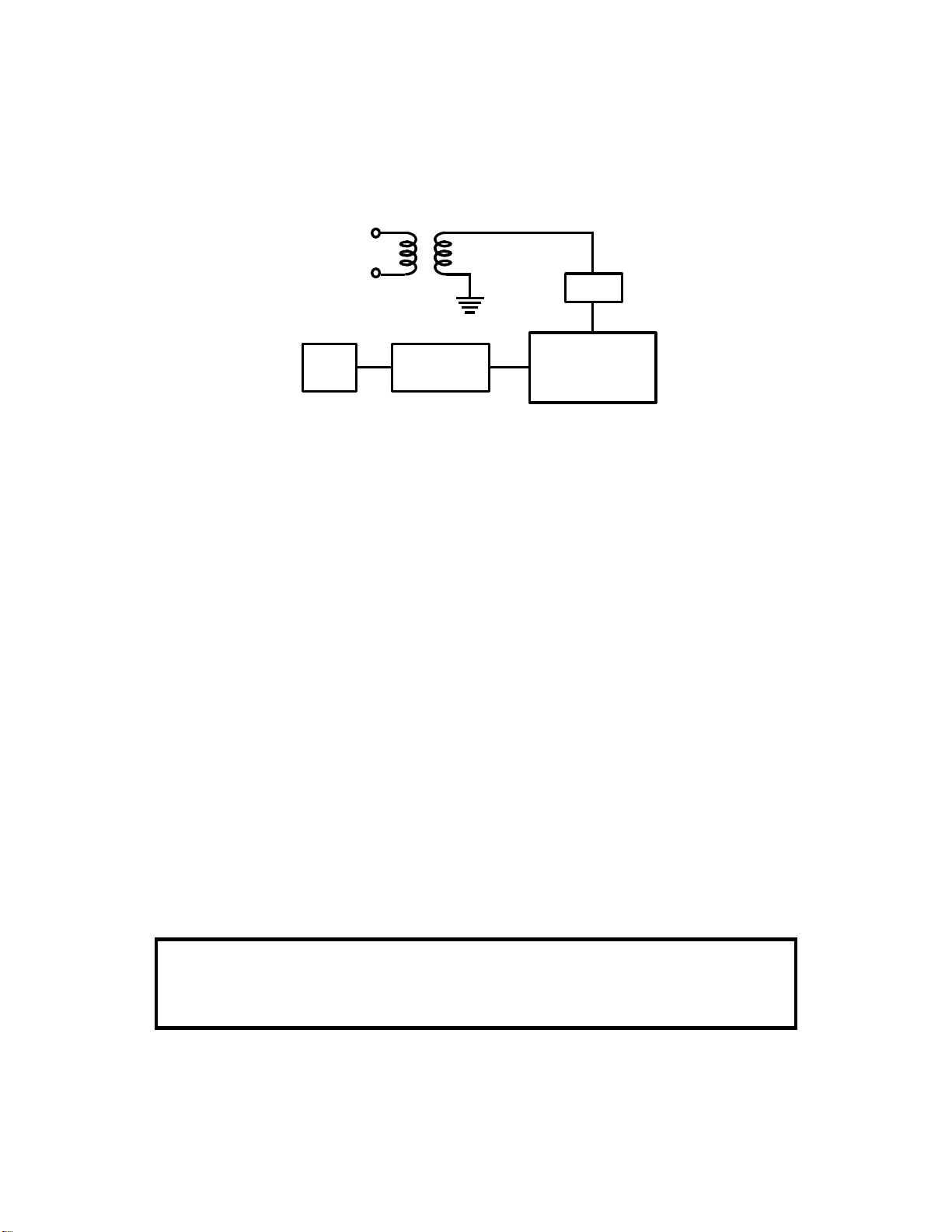
2-7. SIGNAL DETECTION
After dialling, the machine waits for the response from the other end. The response is usually either a CED tone, a busy tone, or a ringback tone. These
tones are known as progress tones. Instead of a progress tone, a protocol
signal such as NSF or DIS may be detected at this time.
From the
Network
Filters
Programmable
Gain
Amplifier
CPU
A/D
Converter
The received signal passes through two filters. A high pass filter (with a cut
off of about 300 Hz) removes low frequencies, such as noise from the fax machine’s power supply, and a low pass filter (with a cut off of about 2100 Hz)
removes high frequencies, such as noise from overhead railway power cables.
The signal then passes to a programmable gain amplifier, which raises the
signal level enough for the machine’s hardware to analyze it. The minimum
signal level on the line will vary from country to country, so the amplifier is programmable. For example, in typical USA models, the amplifier is set up so
that signals weaker than -53 dBm are not detected.
The amplified signal is converted to digital, then passed to the tone detector
in the cpu.
The incoming signal may determine whether or not the machine goes into
transmit mode. Most machines have bit switch or other settings to determine
when the machine goes into transmit mode. The choices are typically as follows:
• After dialling
• After receiving NSF or DIS
• After receiving CED
Note
The gain of the amplifier depends on the country code (the country code is selected by a
bit switch adjustment). However, the gain can be changed by a RAM address adjustment;
in most machines, there are 4 possible values to choose from.
2-7-1
 Loading...