


SECTION 1
OVERALL MACHINE INFORMATION

6 January 1990
1. SPECIFICATIONS
Configuration: Table top
Copy Process: Electrostatic transfer system
Original Feed: Sheet feed
Original Size: Maximum: 914 x 3,600 mm
Minimum: 182 x 257 mm (B5 lengthwise)
Copy Size: Same as "Original Size"
Copying Speed: Manual feed: 5 cpm (A1/D sideways)
Tray feed: 6 cpm (A1/D sideways)
First Copy: 22 seconds (A1 sideways)
Warm-up Time: Within 7 minutes (Room temperature 20
Copy Counter: 1 to 9
o
C)
Automatic Reset: 2 minutes after copying is finished (can be set
to 1, 3, 4, or 5 minutes or to no auto reset)
Photoconductor: Organic photoconductor drum
Drum Charge: Single-wire with grid plate (Negative Charge)
Reproduction Ratio: 1 : 1 (
±0.5%)
Exposure System: Slit exposure via fiber optic array
Exposure Lamp: Fluorescent lamp (65 W)
Development: Dual-component dry toner system
Toner Replenishment: Cartridge system (750 g toner/cartridge)
Toner Consumption: 1,600 A1 or D copies per cartridge (7% original)
Development Bias: Negative
Toner Density Control: Pattern density detection by photosensor and
direct toner density detection by induction
sensor
Image Density Adjustment: Development bias control + exposure control +
grid voltage control
Auto Image Density
Development bias control and exposure control
Control:
1-1

6 January 1990
Image Transfer: Single wire dc corona (negative charge) with
pre-transfer lamp
Paper Separation: Dual wire ac corona and pick-off pawls
Cleaning: Cleaning blade
Quenching: Photo quenching by LEDs
Paper Feeding: Manual feed (auto sheet feeder optional)
Image Fusing: Heat and pressure type, teflon (upper) and
silicone rubber (lower) rollers
Fusing Lamp: Halogen lamp (115 V: 1,100 W, 220/240 V:
1,100 W)
Self-diagnostic Codes: 14 codes, displayed in copy counter
Power Source: 115 V/60 Hz....12 A
220 V/50 Hz....7 A
240 V/50 Hz....7 A
Power Consumption: Maximum: 1.4 kW
Warm-up: 1.2 kW
Ready: 0.1 to 1.2 kW
Copy cycle: 1.4 kW
Ozone Output: Less than 0.1 ppm (1000 ft
at least 3 times per hour)
Dimensions (W x D x H): 1,410 x 800 x 600 mm
55.51 x 31.50 x 23.62 in
Weight: 180 kg, 397 lb
Optional Equipment: ---- Automatic sheet feeder
---- Roll cutter
---- Paper spool
3
room, air turnover
1-2

2. OPERATOR CONTROLS
2.1 OPERATION PANEL
6 January 1990
9
8
7
6
5
4
10
11
12
13
14
15
16
3
17
2
18
1
19
26
25
24
1. Manual Image Density
Indicators
Show the image density level
selected by the Lighter and Darker
keys.
20
21
22
23
2. Lighter Copy Indicator
There are 14 manual ID levels but
only 7 manual ID LEDs. The Lighter
Copy indicator lights when manual
ID levels from 8 to 14 are selected.
1-3

6 January 1990
3. Wait Indicator
Indicates that the machine is not ready
to copy.
4. Select Paper Key
Press to select manual feed or the auto
sheet feeder.
5. Ready Indicator
Lights when the machine is ready to
make copies.
6. Auto Sheet Feed Indicator
Lights when the auto sheet feeder is
selected.
7. Manual Feed Indicator
Lights when the manual paper feed
mode is selected.
8. Add Paper Indicator
Lights when the auto sheet feeder runs
out of paper.
9. Add Toner Indicator
Lights when it is time to install a new
toner cartridge.
10. Original Misfeed Indicator
Lights if an original misfeeds within the
copier.
11. Misfeed Indicator
Lights if paper misfeeds within the
copier.
12. Close Unit Indicator
Indicates that one of the copier’s units
is open. The copier will not operate until
it is completely closed.
13. Toner Collection Bottle Indicator
Lights when it is time to empty the toner
collection bottle.
15. Copy Counter
Displays the number of copies entered,
the number of copies made, and
service codes.
16. Copy Exit Way Key
Selects either upper or lower copy exit.
17. Lead Edge Erase Indicators
Shows the width of the leading edge
erase margin.
18. Lead Edge Erase Key
Selects the amount of leading edge
erase.
19. Clear Modes Key
Press to clear the copier of previously
entered settings.
20. Clear/Stop Key
Press to cancel the copy number
entered. While copying, press to stop
copy operation.
21. Plus Key
Press to increase the number of copies
to be made. (The maximum repeat
copies is 9.)
22. Minus Key
Press to decrease the number of
copies to be made.
23. Auto Image Density Indicator
Lights when the copier is automatically
controlling the image density.
24. Auto Image Density Key
Press to enter and exit the auto image
density mode.
25. Darker Key
Press to make copies darker
14. Call Service Indicator
Indicates that there are functional
problems within the copier.
26. Lighter Key
Press to make copies lighter.
1-4
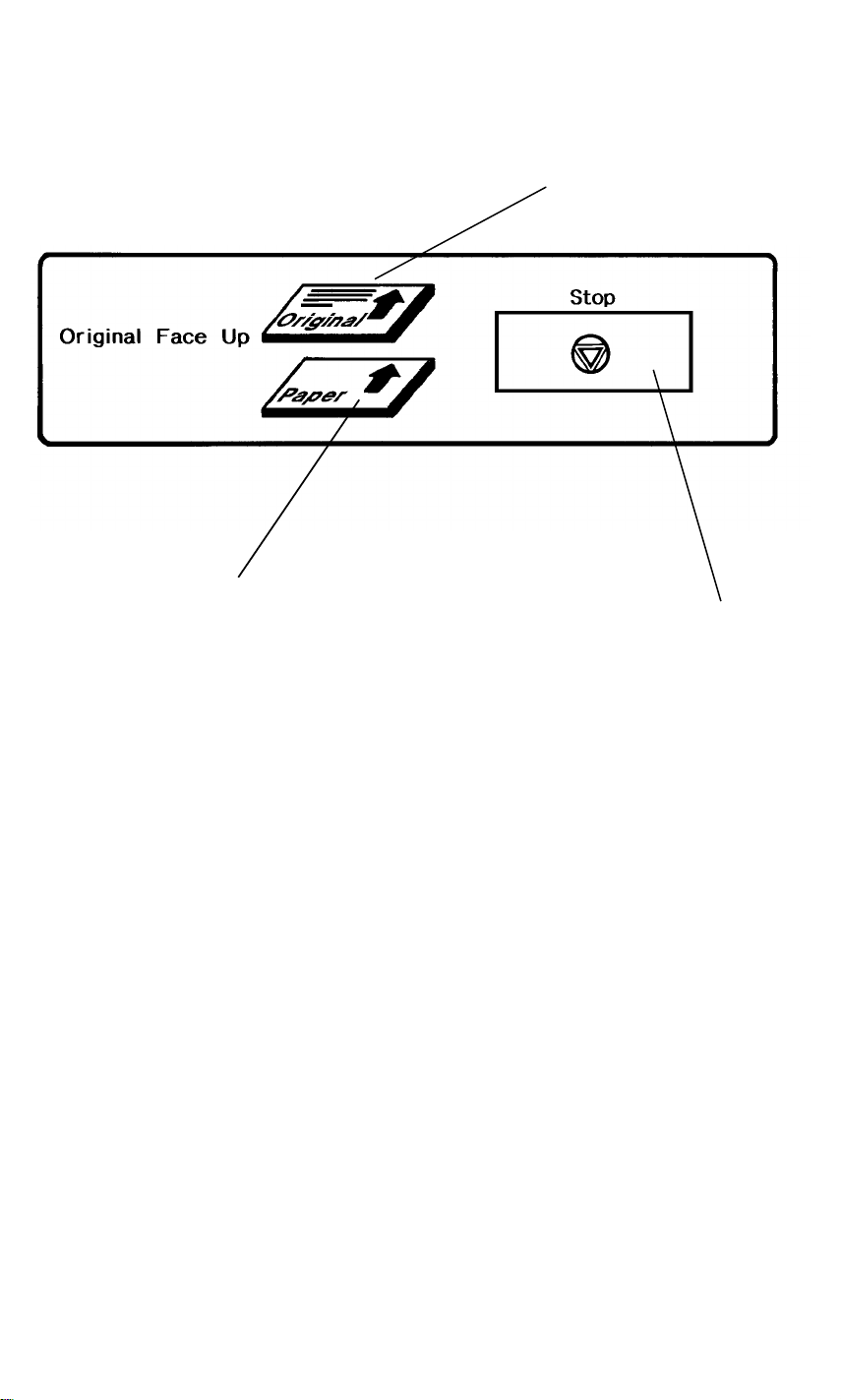
2.2 INDICATOR PANEL
6 January 1990
1
3
2
1. Insert Original Indicator
Lights when the machine is ready for an original to be inserted. Turns off
when an original is inserted.
2. Stop Key
Press to stop the copier during a copy cycle (emergency stop).
3. Insert Copy Paper Indicator
Lights when the machine is ready for a sheet of copy paper to be inserted.
Turns off when a sheet of copy paper is inserted.
1-5

6 January 1990
3. DRUM PROCESSES
12
8
3
7
4
5
6
1. Charge
In the dark the charge corona unit applies a negative charge to the drum.
The grid plate ensures the charge is applied uniformly. The charge remains
on the surface of the drum because the photoconductive drum has a high
electrical resistance in the dark.
2. Exposure
High intensity light from a fluorescent lamp is reflected from the moving
original through the fiber optic array. The charge on the drum surface is
dissipated in direct proportion to the intensity of the reflected light, thus
producing an electric latent image on the drum surface.
1-6

6 January 1990
3. Development
The magnetic developer brush on the development roller comes in contact
with the latent image on the drum surface. Toner particles are
electrostatically attracted to the negatively charged latent image areas.
4. Pre-Transfer Lamp
The pre-transfer lamp illuminates the drum prior to image transfer. This
reduces the attraction between the toner and the drum, thus making image
transfer easier.
5. Image Transfer
Copy paper is fed to the drum surface at the proper time to align the copy
paper and the developed image on the drum surface. Then a strong negative
charge is applied to the back side of the paper. The negative charge pulls
the toner particles from the drum surface onto the paper.
6. Paper Separation
A strong ac corona discharge is applied to the back side of the copy paper,
reducing the charge on the paper and breaking the electrostatic attraction
between the paper and the drum. Then, the stiffness of the copy paper
causes it to separate from the drum. The pick-off pawls help to separate
paper which has low stiffness.
7. Cleaning
The cleaning blade removes any toner remaining on the drum surface.
8. Quenching
The light from the quenching lamp electrically neutralizes the surface of the
drum.
1-7

6 January 1990
4. MECHANICAL COMPONENT LAYOUT
8
6
7
5
10
12
9
11
14
13
15
16
17
18
19
4
20
3
21
22
2
1
23
24
25
26
27
28
3940
1. 1st Feed Detector
2. 2nd Feed Detector
3. Toner Cartridge
4. 5th Press Roller
5. Original Recycle Gate
6. Original Set Detector
7. Front Original Feed Roller
8. 1st Press Rollers
9. Original Exit Detector
10. 1st Original Transport
Detector
11. Exposure Lamp
12. Platen Roller
13. Fiber Optic Array
14. Charge Corona Unit
38
36
34
37
15. 2nd Original Transport
Detector
16. Original Registration
Rollers
17. 4th Press Rollers
18. 2nd Press Rollers
19. Rear Original Feed Roller
20. 3rd Press Rollers
21. Quenching Lamp
22. Upper Exit Rollers
23. Upper Exit Sensor
24. Exit Rollers
25. Exit Gate
26. Exit Detector
27. Lower Exit Sensor
35
32
33
31
30
28. Hot Roller
29. Pressure Roller
30. Transport Belt
31. Transport Sensor
32. Cleaning Unit
33. Pick-off Pawls
34. OPC Drum
35. T/S Corona Unit
36. Paper Registration Rollers
37. Pre-Transfer Lamp
38. Registration Sensor
39. Development Unit
40. Manual Feed Rollers
29
1-8

5. DRIVE LAYOUT
6 January 1990
28
27
26
25
24
23
29
2
3
4
5
6
7
8
10
9
1
11
12
13
14
22
1. Original Drive Belt 2
2. Rear Original Feed Rollers
3. Original Drive Clutch
4. Main Drive Motor
5. Original Registration Rollers
6. Original Drive Belt 3
7. Platen Roller
8. Front Original Feed Rollers
9. Development Roller Gear
10. Auger Gear
21
19
11. Toner Supply Clutch
12. Development Motor
13. Paper Feed Clutch
14. Paper Feed Drive Chain
15. Development Drive Belt
16. Paddle Roller Gear
17. Registration Roller Clutch
18. Drum Drive Gear
19. Toner Collection Coil Gear
20. Feed/Fusing Drive Belt 2
1820
17
16
21. Fusing Drive Chain
22. Drum Drive Belt
23. Feed/Fusing Drive Belt 1
24. Transport Roller Sprocket
25. Hot Roller Sprocket
26. Lower Exit Roller Sprocket
27. Exit Roller Drive Chain
28. Upper Exit Roller Sprocket
29. Original Drive Belt 1
15
1-9

6 January 1990
6. ELECTRICAL COMPONENT LAYOUT
6.1 MIDDLE AND UPPER SECTIONS
1
43
7
5
3
4
2
6
8
10
9
11
12
14
13
16
15
17
18
19
20
42
40
39
41
37
38
36
35
34
33
32
31
1-10
30
29
28
27
26
25
21
22
23
24

6.2 LOWER AND FUSING SECTIONS
6 January 1990
44
65
45
46
47
48
49
50
51
52
53
54
55
56
57
64
63
62
1-11
61
60
59
58

6 January 1990
1. Development Motor
2. Development Motor
Capacitor
3. Charge/Bias PP
4. Lamp Regulator
5. Main Motor Capacitor
6. Light Sensor
7. Cooling Fan
8. Original Feed Clutch
9. Main Motor
10. Indicator Panel
11. 1st Original Transport
Detector
12. Original Registration
Sensor
13. 2nd Original
Transport Detector
14. Auto Density Sensor
15. Upper Exit Sensor
16. Exit Sensor
17. Lower Exit Sensor
18. Pattern Shutter SOL
19. Upper Safety Switch
20. Rear Safety Switch
21. Exit Gate SOL
22. Pulse Generator
23. Exhaust Fan
24. Toner Overflow
Sensor
25. Recycle Gate SOL
26. Main Board
27. Exposure Lamp
28. Recycle Gate
Detector
29. Operation Panel
30. Pre-Transfer Lamp
31. ID Sensor
32. Pick-off Pawl SOL
33. Registration Sensor
34. 2nd Feed Detector
35. 1st Feed Detector
36. Toner Density Sensor
37. Paper Stopper SOL
38. Original Exit Detector
39. Original Set Detector
40. Original Stopper SOL
41. Quenching Lamp
42. Toner Cover SW
43. Toner Supply SOL
44. Manual Feed SOL
45. Registration SOL
46. Fusing Lamp
47. Transfer/Separation
PP
48. DC Power Supply
49. Hot Roller Thermistor
50. AC Controller 2
51. AC Controller 1
52. Fusing Thermofuse
(x2)
53. Pressure Roller
Thermistor
54. Triac
55. Vacuum Fan
56. Circuit Breaker
57. Noise Filter
58. AC Terminal Block
59. Auto Feeder Safety
Switch
60. Main Switch
61. Total Counter
62. Lower Safety Switch
63. Vacuum Fan Motor
Capacitor
64. Transport Sensor
65. Anticondensation
Heater
1-12

6 January 1990
7. ELECTRICAL COMPONENT DESCRIPTIONS
SYMBOL NAME FUNCTION LOCATION
Motors
M1 Main Motor Drives all mechanical components
except the development unit and the
fans. (100 Vac)
M2 Development
Motor
M3 Exhaust Fan
Motor
M4 Cooling Fan Mo-
tor
M5 Vacuum Fan Provides suction so that paper is held
Magnetic Clutches
MC1 Original Feed
Clutch
MC2 Registration
Clutch
Solenoids
Drives the development unit. (100 Vac) 1
Removes heat from around the fusing
unit. (100 Vac)
Provides air flow to the optics cavity.
(100 Vac)
firmly on the transport belts and
rollers. (100 Vac)
Drives the original feed mechanism. 8
Drives the registration rollers. 45
9
23
7
55
SOL1 Toner Supply
Solenoid
SOL2 Pattern Shutter
Solenoid
SOL3 Exit Gate Sole-
noid
SOL4 Pick-off Pawl
Solenoid
SOL6 Paper Stopper
Solenoid
SOL7 Manual Feed
Solenoid
SOL8 Recycle Gate
Solenoid
Turns on to supply toner to the
development unit.
On ID check cycles, this solenoid
turns on to move the pattern plate into
the light path.
Controls the position of the exit gate.
(When ON, the paper exits downward;
when OFF, the paper exits upward.)
Moves the pick-off pawls against the
drum.
Moves the paper stopper down to
prevent paper from being inserted.
Turns ON to engage the manual feed
clutch.
Controls the position of the recycle
gate. (ON = recycle gate in down
position,
OFF = recycle gate in up position.)
1-13
43
18
21
32
37
44
19

6 January 1990
SYMBOL NAME FUNCTION LOCATION
SOL9 Original Stopper
Solenoid
SOL10 Auto Feeder So-
lenoid 1
SOL11 Auto Feeder So-
lenoid 2
Moves the original stopper down to
prevent an original from being inserted.
Turns the paper feed roller of the auto
sheet feeder.
turns the relay rollers of the auto sheet
feeder.
40
----
----
Switches
SW1 Main Switch Supplies power to the copier. 60
SW2 Upper Safety
Switch
SW3 Lower Safety
Switch
SW4 Rear Safety
Switch
SW5 Toner Cover
Switch
Cuts ac 100 volt power when the
upper unit is opened.
Cuts ac 100 volt power when the
middle unit is opened.
Cuts ac 100 volt power when the
paper exit unit is opened.
Cuts power to the toner supply
solenoid and the main motor when the
25
62
20
42
toner cartridge cover is opened.
SW6 Auto Feeder
Safety Switch
Prevents main motor operation when
the auto feeder is not set.
59
Sensors and Detectors
S1 Image Density
Sensor
S2 Toner Density
Sensor
S3 Toner Overflow
Sensor
S4 Pulse Generator Supplies timing pulses to the main
Detects the image density of the test
pattern on the drum.
Detects the density of toner in the
developer.
Detects when the used toner tank is
full.
31
36
24
22
board (photointerrupter).
S5 Original Set De-
Detects when an original is inserted. 39
tector
S6 1st Original
Monitors movement of the original. 11
Transport
Detector
S7 2nd Original
Monitors movement of the original. 13
Transport
Detector
S8 Original Regis-
tration Sensor
SYMBOL NAME FUNCTION LOCATION
Detects when the original lead edge
passes the original registration rollers.
12
S9
1-14

6 January 1990
Original Exit De-
Monitors movement of the original. 38
tector
S10 Recycle Gate
Detector
S11 1st Feed
Detects whether the recycle gate is in
the up or down position.
Detects when copy paper is inserted. 35
Detector
S12 2nd Feed
Detector
Monitors copy paper movement
between the manual feed rollers and
the registration rollers.
S13 Registration
Sensor
S14 Transport
Sensor
Detects when copy paper arrives at
the registration rollers.
Monitors paper movement between
the transfer/separation section and the
fusing unit.
S15 Exit Detector Monitors copy paper movement
through the exit unit.
S16 Upper Exit
Sensor
S17 Lower Exit
Sensor
S18 Auto Sheet
Feeder Sensor
Monitors copy paper movement
through the upper exit guides.
Monitors copy paper movement
through the lower exit guides.
Detects misfeeds in the auto sheet
feeder.
28
34
33
64
16
15
17
----
S19 Paper End De-
tector
Detects when the auto sheet feeder
runs out of paper.
Printed Circuit Boards
PCB1 Main Board Controls all copier functions both
directly and through other PCBs.
PCB2 DC Power
Supply
Provides dc power for all components
of the machine.
PCB3 AC Controller 1 Provides ac power to the fusing lamp
and triac.
PCB4 Lamp Regulator Provides power to the exposure lamp. 4
PCB5 AC Controller 2 Provides ac power to the main motor
and development motor.
PCB6 Indicator Panel Contains the paper and original
insertion indicators and the original
feed stop key.
PCB7 Operation Panel Contains the operator controls and
indicators.
----
26
48
51
50
10
29
1-15

6 January 1990
SYMBOL NAME FUNCTION LOCATION
Lamps
L1 Exposure Lamp Provides light to reflect the original’s
27
image onto the drum.
L2 Quenching
Lamp
Neutralizes any charge remaining on
the drum surface after cleaning.
41
L3 Fusing Lamp Provides heat to the fusing unit. 46
L4 Pre-Transfer
Lamp (PTL)
Reduces the charge on the drum
surface prior to image transfer.
30
Power Packs
P1 Charge/Bias
Power Pack
Provides high voltage power for the
charge corona, charge grid, and
3
development bias.
P2 Transfer/Sepa-
ration Power
Pack
Provides high voltage power for the
transfer corona and separation
coronas.
47
Thermistors
TH1 Hot Roller
Thermistor
TH2 Pressure Roller
Thermistor
Monitors the hot roller’s surface
temperature.
Monitors the pressure roller’s surface
temperature.
49
53
TH3 Exposure Lamp
Thermistor
Monitors the fluorescent lamp’s
temperature.
----
Thermofuses
TF1 Fusing
Thermofuse
TF2 Exposure Lamp
Thermofuse
Protects against fusing overheat. (Two
thermofuses in parallel.)
Protects against exposure lamp
overheat.
52
27
Heaters
H1 Lamp Heater Warms the scanning lamp. ---H2 Anticondensa-
tion Heater
Keeps moisture from forming inside
the copier.
65
1-16

6 January 1990
SYMBOL NAME FUNCTION LOCATION
Others
CO1 Total Counter Keeps track of the total length of
61
copies made.
NF Noise Filter Filters electrical noise on the ac power
57
input lines.
TR Transformer Steps down the line voltage to 100
----
Vac.
TR Triac Provides ac power to the fusing lamp. 54
1-17

6 January 1990
8. AC POWER DISTRIBUTION
Interlock Switches
SW3 SW4 SW2
Hot
C.B
Main Switch
(SW1)
Neutral
T304
N. F
T306
T307
T305
AC
Controller 1
(PCB3)
Thermofuse(x2)
T309 T1
T310 G
T308
Fusing Lamp(L3)
T2
CN3
-4
-5
Triac
Lamp
Regulator
(PCB4)
Exposure Lamp(L1)
Trans-
fomer
Anticondensation Heater
Exhaust
Fan
M3
Cooling
Fan
CN1
-1
M4
-2
CN3
-1
-2
Vacuum
Fan
Main
Motor
Develop-
ment
Motor
M1
M2
CN402
-1
-2
CN404
-1
-2
AC Controller 2(PCB5)
1-18
M5
CN401-1
CN401-2

6 January 1990
The preceding schematic shows how ac power is distributed in this machine.
The ac power from the wall outlet passes through the noise filter, circuit
breaker, and three interlock switches to the transformer and to ac controller
1.
AC controller 1 powers the fusing lamp with direct wall outlet ac power.
The main board controls the fusing lamp through the triac.
The transformer steps the ac power down to 100 volts and then provides it to
the main switch. If the main switch is off, power is applied only to the
anticondensation heater. If it is on, at 100 volts goes to the fan motors, ac
controller 2, and the lamp regulator.
AC controller 2 provides ac 100 volts power to the main motor and
development motor. RA401/402 turn the motors on and off.
1-19

6 January 1990
9. DC POWER SUPPLY
FU1
CN1-1
AC LINE
5A
ZNR
CN2-1
S
W
I
C
H
I
N
G
Vcc
C. GND
CN2-2
DC5V
C
O
N
T
CN1-3
AC NEUTRAL
R
O
L
FG
Vaa
FU2
8A
Above is a simplified schematic of the dc power supply.
The dc power supply provides +5 volts (Vc) and +24 volts (Va) from CN2-2
and CN2-7 respectively to the main board. Also +24 volts (Va) is provided to
the charge/bias power pack from CN2-6 and to the transfer/separation power
pack from CN2-8.
CN2-3,4,5
A. GND
CN2-6,7,8
DC24V
1-20

SECTION 2
DETAILED SECTION DESCRIPTIONS

6 January 1990
1. DRUM
1.1 DRUM CHARACTERISTICS
The organic photoconductor (OPC) drum has the following characteristics:
• It is able to accept a high negative electrical charge in the dark. (The elec-
trical resistance of the OPC drum is high in the absence of light.)
• The electric charge on the drum surface dissipates when the drum is ex-
posed to light. (The conductivity of the OPC drum is greatly enhanced by
exposure to light.)
• Dissipating an amount of charge in direct proportion to the intensity of the
light. That is, where stronger light is directed to the photoconductor surface, a smaller voltage remains on the selenium.
The OPC drum used in this model has high sensitivity, good color
reproduction, and good reproduction of low contrast originals (pencil originals,
etc.)
1.2 HANDLING THE DRUM
The organic photoconductor drum is very sensitive to light, temperature, and
corrosive gases. Please observe the following cautions when handling the
OPC drum.
1. Never expose the drum to sunlight.
2. Never expose the drum to light of more than 1000 Lux for more than a
minute.
3. Never touch the drum surface with bare hands. When the drum surface is
touched with bare hands or becomes dirty, wipe with a dry cloth or clean
with wet cotton. Wipe with a dry cloth after cleaning with wet cotton.
4. Never use alcohol when cleaning the drum. (Alcohol tends to dissolve the
OPC layer.)
5. Store the drum in a cool, dry place away from heat.
6. Take care not to scratch the drum as the OPC layer is thin and easily
damaged.
7. Never expose the drum to corrosive gases such as ammonia gas.
2-1

6 January 1990
1.3 DRUM DRIVE
[F]
[B]
[E]
[D]
[C]
[G]
[J]
[H]
[I]
[A]
The OPC drum [A] is 80 millimeters in diameter and 970 millimeters long. It
turns constantly when the main motor [B] is on.
When the main motor turns on, drive is transmitted to the drum as follows:
main motor drive gear [C] ⇒ idle gear [D] ⇒ main drive pulley gear [E] ⇒ drum
drive belt [F] ⇒ drum drive gear [G] ⇒ drum flange [H] ⇒ drum
When the drum knob [I] is tightened, the right flange [J] presses firmly against
the drum so that the drum is held tightly between the flanges. The drum and
flanges turn together when the main motor is on.
2-2

2. CHARGE
2.1 OVERVIEW
6 January 1990
P1
[A]
[B]
Charge
P1
Grid
This model uses a single wire corona unit [A] to charge the OPC (organic
photoconductor) drum [B]. The corona wire generates a corona of negative
ions when a high negative voltage is applied to it by the charge/grid power
pack [P1].
To make the negative corona uniform, a grid consisting of 8 wires is installed
on the charge corona unit between the corona wire and the drum. This grid
drains off any charge in excess of --940 volts, thus preventing fluctuation of
the charge potential.
2-3

6 January 1990
2.2 CHARGE CORONA CIRCUIT
Charge / Bias PP
DC/DC
Converter
DC/DC
Converter
CN1-1
CN1-2
CN1-3
CN1-6
CN1-10
CN2
-6
CN107
-B14
CN110
-1
-8
DC Power
24V Va
GND
Main Board
24
Charge
Grid Drive
0/5
Grid monitor
0
2.5
The main power supply board supplies +24 volts (Va) to the charge/bias
power pack as the power supply source. About 8 seconds after the Start key
is pressed, the CPU drops CN107-B14 from +24 volts to 0 volt. This actuates
the dc/dc converter within the power pack which applies a high negative
voltage of approximately --5.3 kV to the charge corona wire. The corona wire
then generates a negative corona charge.
The grid limits the maximum corona charge to --940 volts. This ensures that
the charge does not fluctuate and an even charge is applied to the drum
surface. When developing the test pattern for the image density sensor, the
grid charge is --460 volts.
The copy grid voltage, and ID sensor grid voltage amounts can be adjusted
using service program modes #23 and #22, respectively.
The grid drive signal applied to CN1-6 is a pulse width modulated signal. As
the width of the pulses applied increases, the strength of the grid charge also
increases. The main board monitors the grid charge at CN110-8 and controls
the width of the drive pulses based on this feedback.
2-4

3. EXPOSURE
3.1 OVERVIEW
[A]
6 January 1990
[D]
[F]
[E]
[B]
Light from the exposure lamp [A] reflects off the original and through the fiber
optics [B] to the OPC drum [C]. During exposure, the original moves across
the exposure glass at the same speed as the drum’s peripheral velocity.
The platen roller [D] presses the original [E] flat against the exposure glass [F]
just above the fiber optic array. This ensures that the image is properly
focused. (The original must be within 0.2 mm of the exposure glass surface.)
The exposure lamp is a 100 V, 65 W fluorescent lamp. This lamp has a heater
which prevents a reduction in light output due to low temperatures. The heater
maintains the lamp’s temperature at 40oC
[C]
2-5

6 January 1990
3.2 ORIGINAL FEED
3.2.1 Basic Operation
[G]
[F]
[I]
[B]
[A]
[C]
[H]
[L]
[J]
[K]
[E]
When the original is inserted on the original table [A], it activates the original
set detector [B]. The main motor then turns on. Two seconds later the original
feed clutch turns on to start turning the front original feed rollers [C], rear
original feed rollers [D], and original registration rollers [E]. The two second
delay allows time for the operator to align the lead edge of the original against
the first set of rollers to prevent skew.
[D]
The original is fed past the 1st and 2nd original transport detectors [F,G] and
around the rear original feed rollers to the original registration rollers. The
original feed clutch turns off 0.2 second after the original’s leading edge
activates the original registration sensor [H]. The original remains at this
position until a sheet of copy paper is fed.
Just before the copy paper reaches the registration sensor, the original feed
clutch turns on again and original feed resumes. The original passes between
the platen roller [I] and the exposure glass [J] and from there to the front
original feed rollers. The original’s image density is measured by the ADS at
this time. The original’s image is reflected through the fiber optic array to the
drum as it passes between the platen roller and the exposure glass.
If making a single copy, the original then exits the machine. However, if
making repeat copies, the recycle gate [L] directs the original around the front
original rollers to the upper part of the original transport mechanism. The
original transport cycle then repeats.
The maximum original length for repeat copying is 610 millimeters. If the
operator attempts repeat copying with an original longer than 610 millimeters,
it will automatically feed out after making a single copy.
2-6

3.2.2 Drive Mechanism
[A]
6 January 1990
[B]
[C]
Drive power from the main motor is provided to the original transport
mechanism from the original drive pulley through original drive belt 2 [A].
When the original drive clutch [B] is energized, original drive belt 3 [C] starts
turning the front original feed rollers and the original registration rollers. The
rear original feed rollers are driven directly by the original drive clutch.
2-7

6 January 1990
3.3 ORIGINAL STOPPER MECHANISM
[A]
[B]
Originals should not be inserted during a copy cycle. To prevent originals from
being inserted, the machine locks the feeler of the original set detector in the
down position while copying. This is accomplished by the original stopper
solenoid [A].
When the original stopper solenoid turns on, the stopper arm [B] rotates
against the feeler of the original set sensor. This locks the feeler in the down
position so that originals can only be inserted as far as the original set sensor.
2-8

3.4 EXPOSURE LAMP CONTROL
[PCB4]
6 January 1990
+5V
PWM
CN1-1
CN1-2
CN2-1
CN2-2
CN2-2
LAMP
REGULATOR
T
CN3-1
CN3-2
CN3-4
CN3-5
Lamp OFF (+5V)
Lamp ON (GND)
T = 1.0 ms
Duty = 15% to 100%
[L1]
Exp. Lamp
The lamp regulator receives 100 volts ac at CN1-1 and CN1-2. It also
receives +5 volts, which is used in the lamp regulator’s control circuit, from the
main board at CN2-1. The control signal, which is a pulse width modulated
(PWM) signal, is received at CN2-2. The PWM signal has a period (T) of 1
millisecond and a duty of 15% to 100%.
The basic light intensity level is determined either by the image density
selected from the operation panel (manual ID control) or by the original’s
background level as sensed by the ADS. The CPU uses the light sensor to
monitor the actual light intensity. The light sensor directly senses the lamp’s
light output and feeds a light intensity signal back to the main board. This
feedback allows the CPU to compensate for variations in light intensity due to
the lamp’s age or temperature.
2-9

6 January 1990
3.5 MANUAL ID CONTROL VS ADS
1.4
Light
Sensor
Output
(Volts)
1.2
1.0
0.8
0.6
1 2
3 4
6
5
7
9 10 11
8
12
13
14
Manual ID Level
Darker Lighter
3.5.1 Manual ID Control
When in manual image density mode, the user can select one of 14 manual
ID levels. For each level, the intensity of the light output by the exposure lamp
(as measured by the light sensor) is fixed. This is shown in the above graph.
For manual ID levels 2 through 7, the development roller bias also varies.
(See the section on development bias.)
2-10

Vod/Vsd VS [V]
0 ∼ 0.18 0.86
0.19 ∼ 0.46 1.74
0.47 ∼ 0.49 1.64
0.50 ∼ 0.53 1.54
0.54 ∼ 0.57 1.45
0.58 ∼ 0.61 1.37
0.62 ∼ 0.65 1.29
0.66 ∼ 0.69 1.21
0.70 ∼ 0.73 1.15
0.74 ∼ 0.77 1.05
0.78 ∼ 0.85 0.94
6 January 1990
0.86 ∼ 0.86
VS: Light Sensor Voltage
VOD: Original Density Detecting Voltage
VSD: Standard Pattern (White Plate) Density Detecting Voltage
3.5.2 ADS Control
When automatic image density sensing (ADS) is used, the exposure light
intensity varies depending on the background image density of the original.
The preceding table shows how the exposure light intensity changes
depending on the VOD/VSD ratio.
Use service program mode #10 to select the default ID setting. It can be set to
ADS or Manual ID level 4. The factory setting is ADS.
NOTE: If the exposure lamp cannot output sufficient light, service call
condition "E1" exists. However, copying is still possible. Refer to the
"SERVICE CALL CONDITIONS" table.
2-11

6 January 1990
3.6 AUTO DENSITY SENSOR (ADS)
[A]
Center Line
10mm
Sampled Area
33.5 mm
18 mm
The ADS [A] measures the reflectivity of the original’s background. Based on
the originals background image density, the CPU automatically adjusts the
development bias and exposure light intensity to achieve a good copy image.
The ADS is located at the original registration rollers. It reads the white plate
(standard white), which is located above the ADS, prior to the arrival of the
original. This standard white level (VSD) is used for comparison with the
background level of the original (VOD).
The ADS samples a 43.5 mm by 10 mm area near the leading edge of the
original. As shown in the above illustration, sampling starts 15 mm from the
leading edge.
The highest voltage detected by the ADS is held (peak hold) and used for the
exposure voltage adjustment.
2-12

3.6.1 ADS Circuit
6 January 1990
R404
PD-
401
6
5
LAMP401
IC401
D401
7
C404
C403
2
3
R403
R401
IC401
CN401-1
8
1
4
C401
R402
C402
CN401-3
CN401-5
CN401-2
CN401-4
CN401-6
CN401-7
Vcc(+5V)
ADS:OUT
ADS ADJUST
C-GND
ADS RESET
Vcc(+5V)
SENSOR LAMP
The ADS circuit is powered by +5 volts, which is provided at CN401-1 for the
detection circuit and CN401-6 for the lamp. The CPU resets the ADS by
dropping CN401-4 to 0 volt; this discharges C403 to reset the peak hold
function. The resistance of PD401 varies with the strength of the light striking
it. The two op-amps amplify the effect of the change in PD401 and output the
ADS signal at CN401-3.
2-13

6 January 1990
3.7 LAMP HEATER
[A]
[B]
This copier uses a fluorescent lamp [A] as the exposure light source. The
output of the exposure lamp varies depending on the temperature; low
temperatures especially degrade the light output. To prevent fluctuations in
temperature from affecting the copy image, the lamp heater [B] keeps the
lamp’s temperature at 40°C.
2-14

3.8 LAMP HEATER CONTROL CIRCUIT
6 January 1990
AC 100 V
PCB1
L. Heater ON
TH3
Short
TH3
Input
TH3
Open
Va2424
00/5
GND
00/5
00/5
PCB5
CN107
-A2
-B2
-A1
5Vc
-B3
-A3
-B1
-B4
CN407
-2
-1
CN408
-3
-2
-1
-5
-4
+
SSR
401
Comparator
Circuit
CN401
-2
~
~
-1
CN406-1
H1
CN406-2
CN407-4
TH3
CN407-3
The lamp thermistor, which is mounted together with the lamp heater,
monitors the lamp temperature. Based on the input from this thermistor at
CN107-B1, the CPU on the main board determines whether or not to turn on
the lamp heater. To turn on the lamp heater, the main board drops CN107-B2
to 0 volts. This turns on SSR401 on ac controller 2, which provides ac power
to the heater.
If the exposure lamp thermistor short circuits, the comparator circuit drops
CN107-B3 to LOW. The copier then stops operation, the Call Service
Indicator (wrench mark) lights, and "E" and "8" are alternately displayed in the
Copy Counter.
If there exposure lamp thermistor circuit becomes open, the comparator circuit
changes CN107-B4 from LOW to a 5 volt pulses. The copier then stops
operation, the Call Service Indicator (wrench mark) lights, and "E" and "7" are
alternately displayed in the Copy Counter.
2-15

6 January 1990
4. DEVELOPMENT
4.1 OVERVIEW
[C]
[A]
When the main motor turns on, the paddle roller [A] and development roller
[B] start turning. The paddle roller picks up developer in its paddles and
transports it to the development roller. Internal permanent magnets in the
development roller attract the developer to the development roller sleeve.
The turning sleeve of the development roller then carries the developer past
the doctor blade [C]. The doctor blade trims the developer to the desired
thickness and creates backspill to the cross-mixing mechanism.
[B]
The development roller continues to turn, carrying the developer to the
selenium drum. When the developer brush contacts the drum surface, the
negatively charged areas of the drum surface attracts and holds the positively
charged toner. In this way, the latent image is developed.
Negative bias is applied to the development roller to prevent toner from being
attracted to non-image areas on the drum that may have residual positive
charge. The bias also controls image density.
After turning about 100 degrees more, the development roller releases the
developer into the developer tank. The developer is agitated by the paddle
roller and the cross-mixing mechanism.
Also, in this machine, rotation of the paddle roller and development roller tend
to cause air pressure inside the unit to become higher than the air pressure
around the development unit. Therefore, a hole fitted with a filter, has been
added to the top of the unit to relieve air pressure and to minimize toner
scattering.
2-16

4.2 DRIVE MECHANISM
6 January 1990
[D]
[C]
[F]
[G]
[H]
[B]
[I]
[E]
[A]
To reduce load on the main motor, the development unit uses a separate
drive motor [A]. The development drive pulley turns the development drive
belt [B] which turns the development drive gear [C]. The development drive
gear turns the development roller gear [D] and the paddle roller gear [E]. The
auger gear [F] is engaged with the paddle roller gear. Thus, the development
roller, paddle roller, and auger all turn when the development drive motor is
on.
The toner agitator gear [H] is also turned by an idle gear [G], which is
engaged with the auger gear. However the toner agitator does not turn unless
the toner supply clutch [I] is engaged. It engages when the toner supply
solenoid turns on.
2-17

6 January 1990
4.3 CROSS MIXING
[C]
[B]
[E]
[F]
[A]
[D]
"Crossmixing" keeps the toner and carrier evenly mixed in the developer and
evenly distributes the developer within the development unit. Crossmixing
also agitates the developer to generate the necessary triboelectric charge on
the toner and carrier particles.
The arrows in the above illustration show the developer movement directions
within the machine. The developer that is attracted to the development roller
[A] is split into two parts by the doctor blade [B]. One part (the magnetic
brush) goes on to develop the latent image on the drum. However, the other
part is trimmed off by the doctor blade and directed to the backspill plate [C].
As the developer slides down the backspill plate to the screw roller [D], part of
the developer falls into the auger inlets [E] and is transported to the left side of
the unit by the mixing auger [F], where it drops onto the paddle roller. As the
paddle roller rotates, its blades move the developer to the right. The amount
of developer moved to the right by the paddle roller is equal to the amount
moved to the left by the mixing auger.
2-18

4.4 TONER DENSITY CONTROL
ID Sensor
Check
Toner Sensor
Check
6 January 1990
ID sensor
normal?
No
Toner
sensor
normal?
No
Service Call
indicator ON
Yes
Yes
Toner
density
low?
Yes
Toner supply
solenoid ON
Original
longer than
1200 mm?
Yes
Toner
density
low?
Yes
Toner supply
solenoid ON
No
No
No
The flow chart above illustrates how the copier determines whether or not to
add toner.
This copier uses a dual sensor system to control toner density. The primary
sensor is the ID sensor (image density sensor). This sensor is a photosensor
and directly measures the density of the image on the drum using a test
pattern. This is done just before making the copy. If the test pattern image
density is too low, toner is added.
The secondary sensor is the toner sensor. It measures the ratio of toner to
carrier in the developer. This sensor is used only if the output of the ID sensor
is abnormal or the original is longer than 1200 millimeters. (For very long
originals, it is possible for the toner density to change while the copy is being
made.)
2-19

6 January 1990
4.4.1 Image Density Sensor
5.0
4.0
3.0
Voltage
(V)
2.0
1.0
0.5
LED Light Intensity
Weak Strong
+
_
4.0 0.2V
Standard Intensity
V
Threshold
Level
SG
Toner is
V
SP
0
supplied
No toner
is supplied.
Toner density is detected by developing the sensor pattern and by checking its reflectivity with the image
density sensor (photosensor). Light
from the sensor’s LED reflects from
the drum and activates the phototransistor. The output of the phototransistor goes to CN102-15 of the main
board.
An average reference voltage (Vsg) is
calculated from eight samples of bare
drum reflectivity. After that, an average voltage is calculated from eight
samples of sensor pattern reflectivity.
These two values are then compared
to determine whether toner should be
added or not as follows.
No toner supply condition: Vsp/Vsg < 0.125
Toner supply condition: Vsp/Vsg > 0.125
ID Sensor [S2]
2
1
3
CN102
-14
-15
-12
Main PCB [PCB1]
+5V
CPU
5
CN104
-B10
+24 V
SOL 1
If Vsp/Vsg becomes greater than 0.225, the toner near end condition exists.
The Add Toner indicator then starts flashing. When in the toner near end con-
2-20

6 January 1990
dition, 5.49 meters (=610 mm x 9) can be copied. After that, the toner end
condition is reached. The Add Toner indicator will light and the machine will
not operate.
The ID sensor checks toner density every 1220 mm. If Vsp/Vsg becomes
greater than 0.125 (1/8), then it starts checking toner density every 610 mm.
(If service program mode #21 is set to "1", the toner density will be checked
every 610 mm regardless of Vsp/Vsg.)
The toner supply amount (%) can be adjusted using service program mode
#17.
Using service program #34, Vsp, Vsg, and Vsp/Vsg can be displayed in the
copy counter.
2-21

6 January 1990
4.4.2 Toner Density Sensor
Toner Density Sensor (S2) Main Board (PCB1)
Control
Circuit
1
2
3
4
Coils
CN101-1
[24V] Va
-2
-3
-4
Analog Input
[7.0V] (Control)
GND
The toner density sensor works in conjunction with the ID sensor to control
the amount of toner in the developer mixture. It has three basic functions.
First, it controls the upper and lower limits of toner density. For example, if the
amount of toner in the developer is greater than the upper limit (analog input =
1.9 V), toner supply is prohibited no matter what the ID sensor input is.
(Analog input of 3.5 V is the lower limit.) Second, it checks toner density if an
original larger than 1220 mm is copied. Third, it takes over toner density
control completely if the ID sensor becomes abnormal (=Vsp > 2.5 V or Vsg <
2.5 V).
The toner density sensor is powered by 24 volts from CN101-1 of the main
board. The sensor’s sensitivity is set by the control signal applied from
CN101-1. The input signal from the sensor is applied to CN101-2. This is an
analog signal. When the toner density is at the standard level, the analog
signal is approximately 2.1 volts.
The active sensing element is a very small transformer with three coils. When
iron ferrite (carrier) is near the sensing element, the inductance of the coils
changes, causing the current through the transformer to change. As the
amount of toner in the developer increases, the effect of the carrier particles
decreases and the voltage applied to CN101-2 decreases. Conversely, when
the toner concentration drops due to use, the effect of the carrier on the
sensor coils increases and the voltage at CN101-2 also increases.
Service call "Ed" lights if the toner sensor output becomes less than 1.6 V or
more than 4.7 V
2-22

6 January 1990
4.5 DEVELOPMENT BIAS
4.5.1 Basic Concept
When the drum is exposed, most of the negative charge is eliminated from the
areas where light strikes the drum. This leaves a negative charge pattern
corresponding to the dark areas of the original. After exposure however, a
small residual charge of about --100 volts (for white paper) remains in the
exposed areas. This residual charge could attract positively charged toner
from the development roller and result in dirty background on the copy.
The development bias prevents such dirty background. A negative bias a little
larger than the residual charge is applied to the development roller. This
prevents the positively charged toner from being attracted to the background
areas of the latent image.
Manual ID Bias
Bias
(Volts)
-280
-240
-200
-180
-160
-120
1 2 3 4 5 6 7-14
Manual ID Setting
4.5.2 Manual Image Density Bias
When in manual image density mode, the development bias is applied as
shown by the above chart.
In addition to the development bias, the image density is also controlled by
varying the exposure light intensity. (See the exposure section.)
2-23

6 January 1990
Lighter
ADS
-300
-260
-220
-200
Normal
ADS
-280
-240
-200
-180
0.18 0.85
0.77
0.73
0 0.1 0.2 0.3 0.4 0.5 0.6 0.7 0.8 0.9 1.0
Darker
ADS
-260
-220
-180
-160
ADS Vod/Vsd
Vod: Original Density Detecting Voltage (ADS out put voltage)
Vsd: Standard Pattern (White Plate) Density Detecting Voltage
4.5.3 Auto Image Density Bias
The above chart shows the development bias when in ADS mode. The ADS
can be switched to the "Darker" setting with service program mode #20.
In addition to the development bias, the image density is also controlled by
varying the exposure light intensity. (See the exposure section.)
4.5.4 Bias Adjustment
Bias
Adjustment
(Volts)
-40
-20
0
+20
+40
1 2 3 40
Program Mode #19
Using service program mode #19, the bias level can be increased or
decreased as shown in the above chart.
2-24

6 January 1990
4.6 IMAGE DENSITY SENSOR BIAS
The ID sensor bias is similar to the development bias; however, it is applied
only when developing the ID sensor pattern.
Basically, the ID sensor bias is fixed. The normal ID bias level is --240 volts,
but it can be changed using service program #18. The following table shows
the possible settings. You should clearly understand the effect of changing
the ID sensor bias. If the ID sensor bias is increased the sensor pattern will
become lighter. This will cause more toner to be added to the developer and
thus copy images will become darker and toner consumption will increase. If
the ID sensor bias is decreased, lighter images and less toner consumption
will result.
Service Program #18
Setting 0 1 2 3
ID Bias --240 --200 --280 --320
Factory Setting
A developer counter correction is applied to the ID sensor bias to compensate
for changes in the triboelectric properties of the developer as a new developer
mixture is broken in. The following table shows this correction. Notice that the
correction depends on the average Vsp/Vsg ratio as measured during initial
conditioning as well as on the developer counter. By factoring in the initial
conditioning Vsp/Vsg ratio, this correction compensates for slight variations
between different lots of developer as well as for changes in the developer
during the break-in period. After the initial conditioning, the copy counter will
display the density level (dL).
Developer Counter Correction
Initial Conditioning
dL
Vsp/Vsg
0--499 Copies 500--999 Copies More than 1000
Developer Counter
1 0--10 --40 V --20 V 0 V
2 10--15 --20 V 0 V 0 V
0 15--20 0 V 0 V 0 V
3 20--25 +20 V +20 V +20 V
4 >25 +40 V +40 V +40 V
NOTE: Perform the initial conditioning by SP#5 whenever the developer
mixture is replaced. Do not perform SP#5 when the drum is replaced.
There is a possibility of dLE being displayed. This means that there
was on ID sensor (Photo sensor) error during the initial conditioning.
2-25

6 January 1990
4.7 TONER SUPPLY
[C]
[B]
[A]
[B]
To allow a compact design, the toner supply mechanism is built into the toner
cartridge. An agitator [A] in the toner cartridge turns when the toner supply
solenoid is on (toner supply spring clutch engaged). As the agitator rotates,
mylar strips [B] on the ends of the agitator force toner through small holes (0.5
mm) in a plastic strip [C] along one side of the toner cartridge. The toner
particles thus ejected from the cartridge fall into the development unit and are
mixed into the developer. The toner agitator turns at 120 rpm and the toner
supply rate is approximately 36 grams per minute.
When supplying toner, the CPU turns on the toner supply solenoid the length
of time required to supply the amount of toner specified by service program
#17.
2-26

5. IMAGE TRANSFER AND PAPER SEPARATION
[A]
6 January 1990
[E]
[B]
[C]
[D]
5.1 PRE-TRANSFER LAMP (PTL)
After the latent image is developed but before the image is transferred to the
copy paper, the drum surface is illuminated by the pre-transfer lamp [A]. This
illumination reduces the negative potential on the drum surface. This prevents
the toner particles from being re-attracted to the positively charged drum
during the paper separation process. It also makes image transfer and paper
separation easier.
5.2 IMAGE TRANSFER
The registration rollers [B] feed the copy paper through the transfer entrance
guides to the transfer section. A high negative voltage (about --5.0 kV) is
applied to the transfer corona wire [C], and the corona wire generates
negative ions. These negative ions are applied to the copy paper, and the
negative charge attracts the positive charged toner away from the drum and
onto the paper. In addition, the paper is held against the drum by the positive
counter charge on the drum.
5.3 PAPER SEPARATION
After image transfer, the copy must be separated from the drum. To break the
attraction between the paper and the drum, the separation corona wires [D]
apply an ac corona (4.0 kV) to the reverse side of the paper. The stiffness and
weight of the paper causes it to separate from the drum.
The separation corona has a negative component of approximately --200
volts. This negative component holds the toner on the paper to prevent it from
being reattracted to the drum during paper separation. The two pick-off pawls
[E] ensure that thin paper, paper with low stiffness, or upward curled paper
separates completely from the drum.
2-27

6 January 1990
5.4 PICK-OFF MECHANISM
[E]
[B]
[A]
[C]
[D]
The pick-off pawl solenoid [A] is energized 12 pulses after the registration
solenoid turns on to feed the copy paper to the drum. The pick-off lever [B]
then rotates clockwise and pushes up the pawl holder [C]. This releases the
two pick-off pawls [D], allowing them to rotate against the drum.
Just after the leading edge of the copy paper passes the transport sensor, the
pick-off solenoid turns off again. The pick-off spring [E] then pushes down the
pawl holder, which moves the pick-off pawls away from the drum.
2-28

5.5 T/S CORONA CIRCUIT
6 January 1990
+24 (Va)
T
-5.0 kV
S
AC 4.0 kV
DC -200 V
[P2]
DC/DC
Converter
DC/DC
Converter
DC/AC
Inverter
CN1-2
A. GND
CN1-1
[PCB1]
CN107CN1
-3
-B12
24
-4
-A13
24
-5
-B13
24
-6
-B11
Not Used
The T/S power pack is powered by +24 volts (Va) from the dc power supply.
The dc/dc converters and dc/ac inverter change the +24 volts to the high
voltages used by the transfer and separation coronas.
T. Trig
T. Sel
S. Trig
The main board (PCB1) turns on the transfer corona by dropping CN107-B12
(T.Trig) from 24 volts to 0 volt. This turns on the dc/dc converter, which
applies a high voltage of approximately --5.0 kV to the transfer corona wire.
The main board turns on the separation corona by dropping CN107-B13
(S.Trig) to 0 volt. The dc/dc converter and dc/ac inverter circuits then apply
approximately ac 4.0 kV and --200 V to the separation corona wires.
Normally, T.Sel is not used. However, if the user presses the Auto Image
Density key for longer than 3 seconds, the CPU uses both T.Trig and T.Sel to
turn on the transfer corona. This increases the transfer corona current from
150 µA (the normal value) to 250 µA. The higher transfer current may be
useful under high humidity conditions (When the higher transfer corona
current is selected, the manual ID display function inverts.)
2-29

6 January 1990
6. CLEANING
6.1 OVERVIEW
[A]
[B]
The cleaning blade [A] removes any toner remaining on the drum after the
image is transferred to the copy paper. The toner that is wiped off by the
cleaning blade drops onto the toner collection coil [B], which then moves it to
the used toner tank.
The cleaning blade pressure spring applies pressure to the exact center of the
cleaning blade so that pressure is evenly applied across the entire length of
the cleaning blade. Blade pressure is applied constantly; however, the blade
pressure can be relieved manually for drum removal.
2-30

6.2 COLLECTION OF USED TONER
[A]
[C]
[E]
6 January 1990
[B]
[D]
The toner collection coil moves used toner from the cleaning unit through the
used toner pipe [A] to the used toner tank [B]. The used toner tank can hold
about 800 grams of toner. On average, about 10,000 A2 sized copies can be
made before the used toner tank needs to be emptied. (This assumes 7%
originals and 80% transfer efficiency.) The toner overflow sensor [C] detects
when the used toner tank is full.
The toner collection bottle is vibrated to prevent used toner from building up in
one place and activating the toner overflow sensor too early. The shaft of the
first set of transport rollers has a cam [D] on the end. This cam is in contact
with a projection [E] of the used toner bottle. It turns when the main motor is
on and moves the used toner tank up and down as shown above right.
2-31

6 January 1990
6.3 TONER OVERFLOW SENSOR
+5 (Vc)
3
Toner Overflow Sensor 3]
[A]
[B]
Main Board
[PCB1]
CN107
-B22
2
1
0/5
0
OSC
Freq.
Detec-
tion
Tr.
Rectifier
The toner overflow sensor [A] signals the CPU when the toner collection bottle
is full.
A small tuning fork [B] is used as the sensing element of the toner overflow
sensor. This tuning fork is a damping element in a multivibrator circuit. As long
as there is nothing in contact with the tuning fork, the vibrating frequency of
the circuit stays low and the transistor stays off.
When toner presses against the tuning fork, the resistance of the piezoelectric
elements that are in contact with the tuning fork changes and the vibrating
frequency increases. The frequency detection circuit passes the higher
frequency signal to the rectifier which activates the switching transistor. The
transistor sends a LOW signal to CN107-B22.
When the CPU detects this LOW signal, it stops the copier and lights the
Toner Collection Bottle indicator.
2-32

7. QUENCHING
[A]
6 January 1990
[B]
+24 V
Quenching Lamp [2]
Main Board
[PCB1]
CN104
-B8
(-B9)
24
After the drum is cleaned, light from the quenching lamp neutralizes any
charge remaining on the drum. The quenching lamp turns on and off at the
same time as the main motor.
The quenching lamp consists of two PCBs containing 49 LEDs (light emitting
diodes) each. The LEDs output light in the 660 nm to 700 nm (red) range. The
main board turns on the quenching lamp LEDs by dropping CN104-B8 and
CN104-B9 to 0 volts. The two PCBs have identical circuits (shown above).
2-33

6 January 1990
8. PAPER FEED AND REGISTRATION
8.1 OVERVIEW
[B]
[A]
[D]
[C]
In this copier, paper is fed either manually or by the auto sheet feeder
(option).
For manual feed, the copy paper is inserted until it contacts the manual feed
rollers [A]. At that time the paper turns on the 1st feed detector [B], which
causes the main motor to turn on. Two seconds after the main motor turns on,
the manual feed solenoid turns on and the manual feed rollers start turning to
feed the paper to the registration rollers [C]. If using the auto sheet feeder,
copy paper feeds through the manual feed rollers automatically after the
original is inserted.
Just before the paper reaches the registration rollers it activates the
registration sensor [D]. The manual feed solenoid turns off 0.4 second after
that. The 0.4 second delay allows the leading edge of the paper to align
against the registration rollers (which are not turning at this time) to eliminate
skew.
The registration clutch turns on to feed the paper to the drum. It is energized
at the proper time to align the leading edge of the paper with the leading edge
of the developed image on the drum.
Fine and coarse registration adjustments can be made using service program
modes #26 and #27 respectively.
2-34

8.2 DRIVE MECHANISM
[A]
[B]
[F]
6 January 1990
[C]
[E]
[D]
Drive power from the main motor is provided to the paper feed and
registration drive mechanism from feed/fusing drive belt 2 [A] through the
manual feed/registration sprocket [B].
When the manual feed solenoid [C] is energized, the paper feed drive chain
[D] drives the manual feed roller [E]. Once the paper reaches the registration
sensor, the registration clutch [F] turns on, thus the registration roller [G] starts
turning.
[H]
[G]
The manual feed/registration sprocket is in contact with the transport/fusing
sprocket [H] which drives the transport and fusing units.
2-35

6 January 1990
9. PAPER TRANSPORT
[A]
[C]
[B]
[C]
[A]
[B]
After separation from the drum, the copy paper rides on the transport belts [A]
and transport rollers [B] to the fusing unit.
Airflow directly from the vacuum fan [C] holds the paper firmly against the
belts so that there is enough friction between the paper and the belts for
smooth transportation of the paper. The transport belts and transport rollers
are directly driven by the fusing drive chain (no clutch or solenoid); so, they
turn constantly when the main motor is on.
2-36

10. FUSING AND PAPER EXIT
10.1 OVERVIEW
6 January 1990
[A]
[C]
[L]
[F]
[D]
[I]
[G]
[H]
[B]
[E]
Two rollers fuse the image to the copy paper by applying heat and pressure.
The hot roller [A] is made of carbon-teflon and the pressure roller [B] is made
of silicone rubber. Pressure is constantly applied by the pressure levers at the
ends of the fusing unit.
The fusing lamp [C], which is located at the hot roller axis, is turned on and off
to maintain the operating temperature. The temperature control circuit (on the
main board) monitors the surface temperature of the hot roller and the
pressure roller through thermistors [D and E respectively].
2-37
[J][K]

6 January 1990
The hot roller strippers [F] separate the copy from the hot roller and direct it to
the fusing exit rollers [G]. After the fusing exit rollers, the exit gate [H] directs
the copy to either the upper or lower exit rollers [I and J].
When the exit gate solenoid is on, the exit gate directs the copy paper down
through the lower copy exit path. If the exit gate solenoid is off, the paper
goes through the upper copy exit path. The exit direction is selected using the
Copy Exit Way key.
A steel cleaning roller [K] removes toner from the pressure roller. This
effectively cleans toner from both the hot roller and pressure roller because
toner on the teflon surface of the hot roller sticks preferentially to the rubber of
the pressure roller. Then, toner on the pressure roller sticks preferentially to
the steel cleaning roller.
Two thermofuses (wired parallel) [L] provide backup overheat protection. (See
the section on fusing temperature control.)
2-38

10.2 DRIVE MECHANISM
10.2.1 Fusing Drive
[A]
[C]
[D]
6 January 1990
[B]
[G]
[F]
[E]
The hot roller is turned by the fusing drive chain as shown. The pressure roller
is friction driven by the hot roller. The fusing rollers turn constantly when the
main motor [A] is on, driven via the gears [B], through feed/fusing drive belts 1
[C] and 2 [D], the sprockets [E] and the fusing drive chain [F], to the hot roller
sprocket [G].
2-39

6 January 1990
10.2.2 Exit Roller Drive
[C]
[E]
[A]
[B]
[D]
The upper [A] and lower [B] exit rollers are driven by the main motor [C] via a
set of gears [D]. Finally, the exit roller drive chain [E] drives the exit rollers
through a sprocket as shown above.
The exit rollers turn constantly when the main motor is on.
2-40
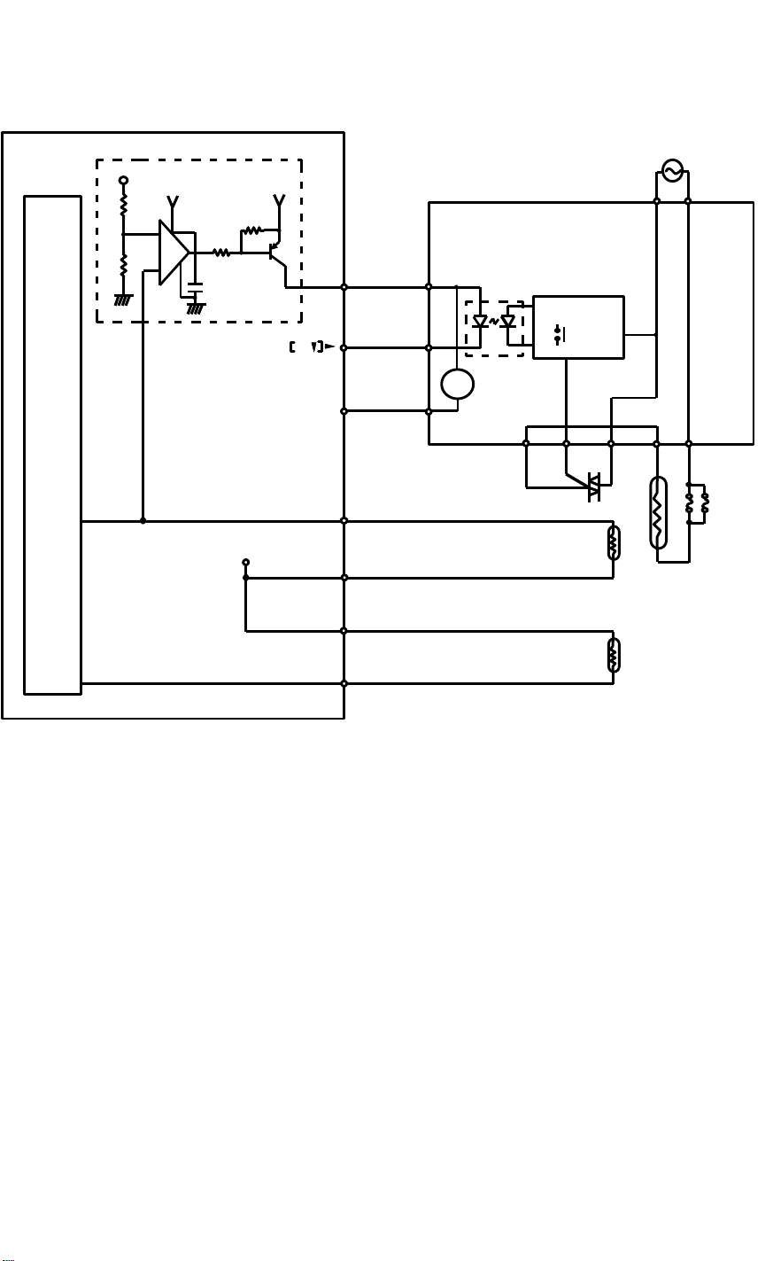
10.3 FUSING TEMPERATURE CONTROL
6 January 1990
Overheat Protection
+5
+24
1K
IC107
6
_
1.3K
7
5
+
C
Q101
+24
24
A.GND
CN301
CN107-A25
CN107-A15
CN107-B25
AC Controller 1 [PCB3]
-5
-6
-3
RA
301
PC301
Drive Circuit
RA301
AC115,220,240
T304 T306
P
U
CN110-12
+5
CN110-11
CN110-9
T309 T310 T308 T307 T305
G
TR
L3
TH1
TH2
TF1
CN110-10
10.3.1 Fusing Circuit Operation
The fusing lamp is powered by AC controller 1 and controlled by the main
board.
AC controller 1 receives direct wall voltage ac power (not stepped down) at
T304 and T306. It also receives +24 volts at CN301-5. The ac power is
applied to the drive circuit, the fusing lamp (L3), and the triac (TR). The dc
power drives PC301 and RA301.
To turn on the fusing lamp, the main board drops CN107-A15 to LOW. This
activates the photocoupler (PC301) which in turn energizes the drive circuit.
The drive circuit turns on the triac to complete the lamp circuit, thus turning on
the lamp.
RA301 guards against a failure of the +24 volt power supply. When +24 volts
is applied at CN301-5, RA301 is energized and its ac contacts stay open. If
the +24 volts power stops, the ac contacts of RA301 close, stopping the drive
circuit and turning off the fusing lamp.
2-41

6 January 1990
10.3.2 Overheat Protection
The overheat protection circuit on the main board turns off the fusing lamp if
the temperature goes too high.
The input from TH1 goes to pin 5 of IC107 as well as to the CPU. As the
temperature of TH1 increases, its resistance decreases and therefore the
voltage at pin 5 of IC107 increases. If this voltage becomes greater than the
voltage at pin 6, the output at pin 7 becomes HIGH. Q101 then turns off and
cuts the +24 volt supply to ac controller 2. The fusing lamp then turns off. The
overheat protection circuit becomes effective at about 220 degrees.
TF1 (2 thermofuses in parallel) provides overheat protection in case a short
bypasses the control and drive circuits. These two fuses will open if they
reach approximately 192 degrees.
2-42

10.4 TEMPERATURE CONTROL
Hot
Roller
Temp.
195
o
10
190
SP #28
185
6 January 1990
180
175
170
165
160
75 80 85 90 95 100 105 110 115
o
8
Pressure Roller Temp.
o
8
SP #29
10
o
120
The main board monitors the temperature of the hot roller through TH1 and
the temperature of the pressure roller through TH2. The CPU determines
whether or not to turn on the fusing lamp based on the combination of the
input from these two thermistors. If the pressure roller is cool, the CPU keeps
the hot roller temperature high. However, if the pressure roller is hot, the CPU
decreases the operating temperature of the hot roller. The above graph
shows the relationship between the temperatures of the hot and pressure
rollers.
The operating temperature of the hot roller and pressure roller can be
adjusted using service programs #28 and #29. These programs are used to
compensate for variations in the response of different thermistors. Service
program #28 adjusts the hot roller temperature and service program #29
adjusts the pressure roller temperature. Both of these service programs shift
the temperature in 2 degree increments. The maximum change is 10 degrees
or --8 degrees. The fusing temperature can be monitored using service
program #32.
Also. the setting for fusing warm-up cycle (after main switch on) can be
adjusted using service program mode #14 to off or from one to three minutes,
in one minute increments.
2-43

6 January 1990
11. OTHERS
11.1 PULSE GENERATOR
[S4]
CN112-1
Main Board [PCB1]
+5V
CPU
CN112-3
CN112-2
The CPU controls the timing of all machine operations based on the number
of pulses it receives from the pulse generator. Pulses are generated by
rotating a disk with slots in it within a photointerruptor. As the disk rotates,
light from the LED activates the phototransistor each time a notch comes
between them. The pulse interval is 3.125 milliseconds.
If no pulses are received for one second during the copy cycle, the machine
will stop and display "Eb" in the copy counter.
2-44

11.2 OPERATION PANEL
6 January 1990
MAIN BOARD (PCB1)
CN106
Scan1
Scan2
Scan3
Scan4
Scan5
Key 1
Key 2
Key 3
Seg a
Seg b
Seg c
Seg d
Seg e
Seg f
Seg g
Seg h
-A11
-A13
-B11
-B13
-A12
CN106
-B15
-B16
-A16
-B7
-B6
-B5
-B4
-B3
-B2
-B1
-A1
CN201
-1
-2
-3
-4
-5
OPERATION PANEL (PCB7)
Key
Matrix
CN202
-1
-3
-2
LED Matrix
-4
-5 -6 -7-9-8 -10 -11
The above illustration shows the copier’s operation panel circuit in block form.
The operation panel circuit is driven by five scan pulse lines. The copier uses
LEDs for displays elements. To light any particular LED, the CPU drops the
appropriate segment line to 0 volt at the same time that the scan line
connected to the LED is being energized.
The CPU monitors the KEY lines (KEY1 to KEY3) to determine if a key has
been pressed. Each KEY line is used to monitor up to four keys on the
operation panel. A specific scan pulse appears at the appropriate KEY line
when a key on the operation panel is pressed.
2-45

6 January 1990
11.3 SOLENOIDS
Main Board [PCB1]
CN-1
[ +24]
SOL
CN-2
[+24] Va
To energize a solenoid, the main board drops CN-1 from +24 volts to 0 volt.
The following table gives the main board connector numbers for the solenoids used in this machine.
Name Symbol CN-1 CN-2
Toner Supply SOL1 CN104-B10 CN104-A10
Pattern Shutter SOL2 CN104-B13 CN104-A13
Exit Gate SOL3 CN109-10 CN109-11
Pick-off SOL4 CN104-B11 CN104-A11
Paper Stopper SOL6 CN104-B12 CN104-A12
Manual Feed SOL7 CN107-B6 CN107-A6
Recycle Gate SOL8 CN106-B10 CN106-A10
Original Stopper SOL9 CN105-B7 CN105-A
2-46

11.4 PHOTOINTERRUPTORS
6 January 1990
Photointerrupter
Photo TR ON
Output LOW
CN-1
CN-3
CN-2
Actuator Plate
Main Board (PCB1)
[+5V]
+5V
0V
0V
GND
Photo TR OFF
Output OPEN
Photointerruptors consist of a plastic encapsulated LED and a phototransistor
separated by an open slot. When the slot is empty, light from the LED
activates the phototransistor, and the sensor outputs a low (0 volt) signal.
When an actuator plate enters the slot, light from the LED is blocked and the
output becomes open. In this machine a +5 volt pulse is present at CN-2
when the output is open.
This machine uses three different types of photointerruptor as shown above
right. However, they all function in the same way.
The following table lists the photointerruptors used in this copier.
2-47

6 January 1990
Name Symbol CN-1 CN-3 CN-2
Pulse Generator S4 CN112-1 CN112-3 CN112-2
Original Set Detector S5 CN105-B4 CN105-A5 CN105-B5
1st Original
S6 CN105-B2 CN105-A3 CN105-B3
Transport Detector
2nd Original
S7 CN105-A1 CN105-B1 CN105-A2
Transport Detector
Original Exit
S9 CN106-A17 CN106-B17 CN106-B18
Detector
Recycle Gate
S10 CN106-A17 CN106-B14 CN106-B18
Detector
1st Feed Detector S11 CN104-B5 CN104-A6 CN104-B6
2nd Feed Detector S12 CN104-A4 CN104-B4 CN104-A5
Exit Detector S15 CN109-7 CN109-8 CN109-9
2-48

6 January 1990
12. SERVICE CALL CONDITIONS
When functional problems occur within the copier, the Call Service indicator
( ) lights. At the same time, "E" and a code number blink alternatively in the
copy counter display.
CODE E1 (Abnormal Exposure Lamp)
Code E1 blinks if the output voltage of the light sensor drops below 0.45 volts
and this condition continues for 20 seconds or more after the exposure lamp
on signal is output.
CODE E2 (Fusing Thermofuse Open)
Code E2 blinks if the fusing temperature does not reach 100oC within 4
minutes after the main switch is turned on.
CODE E3 (Hot Roller Thermistor Open)
Code E3 blinks if the resistance of the thermistor (TH1) is 126.5 kΩ or more, 2
minutes after the fusing lamp turns on.
CODE E4 (Hot Roller Thermistor Short)
Code E4 blinks if the resistance of the thermistor (TH1) is 0.1 kΩ or less, 2
minutes after the fusing lamp turns on.
CODE E5 (Pressure Roller Thermistor Open)
Code E5 blinks if the resistance of the thermistor (TH2) is 1 mΩ or more, 2
minutes after the fusing lamp turns on.
CODE E6 (Pressure Roller Thermistor Short)
Code E6 blinks if the resistance of the thermistor (TH2) is 0.5 kΩ or less, 2
minutes after the fusing lamp turns on.
CODE E7 (Exposure Lamp Thermistor Open)
Code E7 blinks if the resistance of the thermistor becomes 248 Ω or more,
and if this condition continues for 20 seconds.
CODE E8 (Exposure Lamp Thermistor Short)
Code E8 blinks if the resistance of the thermistor becomes 2.4 Ω or less, and
if this condition continues for 20 seconds.
CODE E9 (Fusing Overheat)
Code E9 blinks if the hot roller temperature reaches 200oC.
2-49

6 January 1990
CODE EA (Ready Failure)
Code EA blinks if the machine does not reach the ready condition (Ready
indicator ON) within 14 minutes after the main switch is turned on.
CODE Eb (Abnormal Drive)
Code Eb blinks if the pulse generator does not generate pulses for 1 second
after the main motor turns on.
CODE Ec (Abnormal Total Counter)
Code Ec blinks if the relay in the counter does not turn on or off when the
counter counts up.
CODE Ed (Abnormal Toner Density Sensor)
Code Ed blinks if the sensor voltage (Vts) becomes less than 1.6 volts or
more than 4.7 volts for 1 minute.
CODE EF (Abnormal Condition in ID Sensor)
Code EF blinks if the ID sensor (photosensor) bare drum voltage (Vsg)
becomes less than 2.5 volts, or the sensor pattern voltage (Vsp) becomes
more than 2.5 volts.
NOTE: a) Codes E2, E3, E4, E5, E6, E8,E9, EA, Ec and Ed are indicated
immediately when the abnormal condition occurs and the machine
stops.
b) Codes E1, E7,Eb and EF are not displayed when the condition
occurs. Copies can be made, but image quality may be degraded.
Check for these conditions using service program #58 to #61.
2-50

SECTION 3
INSTALLATION

6 January 1990
1. ENVIRONMENT
1. Temperature Range: 10oC to 30oC (50oF to 86oF)
2. Humidity range: 15% to 90% RH
3. Ambient Illumination: Less than 1,500 Lux (do not exposure to direct sunlight).
4. Ventilation: Room air should turn over at least 3
times/hour.
5. Ambient Dust: Less than 0.15 mg/m3 (4 x 10
oz/yd3)
6. Room Size: More than 10 m3 (13.4 yd3)
7. If the installation place is air-conditioned or heated, place the machine as
follows:
a) Where it will not be subjected to sudden temperature changes
from low to high, or vice versa.
b) Where it will not be directly exposed to cool air from an air
conditioner in the summer.
c) Where it will be directly exposed to reflected heat from a space
heater in the winter.
8. Avoid placing the machine in an area filled with corrosive gases.
(Ammonia level should be less than 5 PPM.)
9. Avoid any area higher than 2,000 m (6,500 ft) above sea level.
-3
10. Place the machine on a strong and level base.
11. Avoid any area where the machine may be subjected to frequent strong
vibration.
3-1

6 January 1990
1.1 MINIMUM SPACE REQUIREMENTS
600 mm
600 mm
600 mm
1000 mm
1. Front: 1,000 mm (39.5 in)
2. Back: 600 mm (24 in)
3. Right: 600 mm (24 in)
4. Left: 600 mm (24 in)
3-2

1.2 POWER SOURCE
1. Input Voltage Level: 115 V/60 Hz....12A
220 V/50 Hz....7A
240 V/50 Hz....7A
6 January 1990
2. Permissible Voltage
±10%
Fluctuation:
3. Permissible Extension Cord: At least 300 V, 30 A capacity and
less than 5 m (5.5 yd) long.
NOTE: a) Be sure to ground the machine. (Do not connect the grounding
wire to a gas pipe.)
b) Make sure the plug is firmly inserted in the outlet.
c) Avoid multi-wiring.
d) Do not set anything on the power cord.
3-3

6 January 1990
2. ACCESSORY CHECK
1
2
3
10
4
6
8
9
5
7
Check the accessories and their quantities according to the following list:
1. Copy Guide.............................................................................1 pc
2. Original Guide.........................................................................2 pcs
3. Left Inner Cover Bracket.........................................................1 pc
4. Pick-off Pawl Unit....................................................................1 pc
5. Right Inner Cover....................................................................1 pc
6. Left Inner Cover......................................................................1 pc
7. Inner Cover Bracket................................................................1 pc
8. Pan-head Screw (M4 x 6).......................................................16 pcs
9. Flat-head Screw (M4 x 6) .......................................................3 pcs
10. Fixing Plate.............................................................................1 pc
3-4

3. INSTALLATION PROCEDURE
3.1 REMOVAL OF SHIPPING RETAINERS
1. Remove all strips
of shipping tape
and accessories.
6 January 1990
2. Open the original
feed unit [A] and remove the two spacers [B] from the
platen roller bearings, and remove
the protective sheet
from the exposure
glass.
B
A
B
3-5

6 January 1990
3. Loosen four screws
and remove the
right middle cover
[C].
4. Remove the screw
[D] fixing the main
board bracket [E]
and open the board
90 degrees.
C
5. Remove the plate
[F] (4 screws), fixing
the right portion of
the upper unit on
the lower unit.
(Keep two screws
for mounting the fixing plate later.)
6. Loosen four screws
and remove the left
middle cover.
E
D
F
3-6

7. Remove the screw
[G] fixing the left
portion of the upper
unit on the lower
unit.
8. Press up the handle
[A] and open the
middle unit [B].
6 January 1990
G
B
9. Install the fixing
plate [C] with the
two screws. Then,
reinstall the
main board bracket.
A
C
3-7

6 January 1990
3.2 MOUNTING THE ACCESSORIES
1. Mount the left inner
cover bracket [A]
with two screws.
A
2. Connect the two
connectors [B] of
the pick-off pawl
unit [C] and fix the
unit with two knob
screws [D]. Make
sure that the two positioning pins of the
main copier are inserted in the two
holes of the pick-off
pawl unit.
C
B
3. Remove the drum
protection sheet [E]
by turning portion
[F] of the main motor counterclockwise.
CAUTION:
Make sure that no
tape is left on the
drum.
D
F
E
3-8

4. Reset the cleaning
blade by pulling the
release lever [G] towards the front side.
5. Close the middle
unit and open the retention unit.
6. Open the toner car-
tridge cover [H].
7. Place a level [I] in
the space between
the cartridge cover
and the developer
entrance.
6 January 1990
G
8. Adjust the level of
the machine by turning the bolts on the
4 machine feet.
H
3.3 SUPPLYING DEVELOPER (3 kg)
1. Open the original
feed unit and the
toner cartridge
cover [A].
2. Remove the sponge
seal [B] from the developer entrance.
3. Plug the power sup-
ply cord into the
wall outlet (socket).
I
3-9
A
B

6 January 1990
4. Turn on DIP SW
101-7 and 8 on the
main board [C].
5. Turn on the main
switch [D].
6. Pour of developer
into the development unit evenly as
shown.
7. Close the cartridge
cover and the original feed unit.
D
C
8. Press the Lighter
key once.
9. Press the Copy Exit
Way key [E] to turn
on the development
motor. Press the
Copy Exit Way key
again after 2 or 3
seconds to turn the
motor off.
10. Repeat steps 8
through 9 until 3 kg
of developer has
been loaded in the
development unit.
11. Turn off the main
switch and DIP SW
101-7 and 8.
E
3-10

3.4 SUPPLYING TONER
6 January 1990
1. Set the toner car-
tridge [A] as shown
in the figure.
2. Remove the sealing
tape [B] on the cartridge and turn the
knob [C] clockwise
unit it stops.
A
B
3-11
C

6 January 1990
3.5 INITIAL CONDITIONING
1. Connect the power
supply cord with the
wall outlet (socket).
2. Turn on DIP SW
101-8.
3. Turn on the main
switch.
4. Press the Lighter
key [A] four times
so that the fourth
segment from the
right of the copy
density indicator
lights.
A
C
5. Press the Plus key
[B] once then press
the Paper Exit Select key [C].
6. Turn off DIP SW
101-8 to start initial
conditioning. (Initial
conditioning stops
automatically when
it is complete.)
B
3-12

3.6 MOUNTING THE COVERS
1. Press up the re-
lease handle [D]
and open the upper
unit.
D
2. Install the right in-
ner cover [E] and
the bracket [F] on
the lower unit. (Use
2 pan-head screws
for the bracket. Use
1 flat-head screw
and 3 pan-head
screws for the right
inner cover.)
6 January 1990
F
3. Install the right mid-
dle cover. (4 screws)
4. Install the left inner
cover [G] on the
lower unit. (2 flathead and 5 panhead screws)
5. Install the left mid-
dle cover.
(4 screws)
E
G
3-13
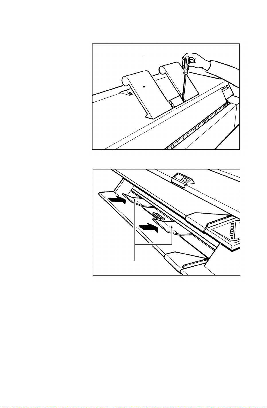
6 January 1990
3.7 MOUNTING GUIDES
1. Install the copy
guide [A]. Use the
two screws that are
already in the correct position on the
top unit.
2. Set the two original
guides [B] as shown
in the figure.
A
3-14
B

SECTION 4
SERVICE TABLES

6 January 1990
1. PREVENTIVE MAINTENANCE SCHEDULE
Symbol key: I = Inspect L = Lubricate R = Replace A = Adjust
C = Clean
A. Original Feed_________________________________________________
EM 3.6km 7.2km 10.8km 14.4km 18km Notes
(6k) (12k) (18k) (24k) (30k)
1. Front original feed
roller
2. Rear original feed
roller
3. Original registration
rollers
4. Platen roller C C C C C C Clean with a
5. Press rollers I C C Clean with a
6. White plate C C C C C C Clean with a
7. AD sensor C C C C C Clean with a
8. Timing belts I I I I I Adjust if nec-
9. Original table C C C C C C Clean with
C C Clean with a
damp cloth
C C Clean with a
damp cloth
C C Clean with a
damp cloth
damp cloth
damp cloth
damp cloth
blower brush
essary
water or isoprophyl alcohol
B. Optics_______________________________________________________
EM 3.6km 7.2km 10.8km 14.4km 18km Notes
(6k) (12k) (18k) (24k) (30k)
1. Fiber optic array Clean with
lens paper
when necessary
2. Exposure lamp Clean with a
damp cloth if
necessary.
3. Exposure glass C C C C C C Water or
glass cleaner
4-1

6 January 1990
C. Development _________________________________________________
EM 3.6km 7.2km 10.8km 14.4km 18km Notes
(6k) (12k) (18k) (24k) (30k)
1. Developer R
2. Side seals I I I I I Replace if
damaged
3. Development filter R R
D. Around Drum_________________________________________________
EM 3.6km 7.2km 10.8km 14.4km 18km Notes
(6k) (12k) (18k) (24k) (30k)
1. Corona wires C C C C C C Clean with a
dry cloth. Replace at 20
K (if necessary)
2. Grid wires C C C C C C Clean with a
dry cloth
3. Charge corona end-
block casing
4. T/S corona end-
block casing
5. Ozone filter R R R R R
6. Quenching lamp I I I I C Clean with a
7. Pick-off pawls C C C C C Clean with a
8. Pre-transfer lamp C C C C C Clean with a
9. ID sensor C C C C C Clean with a
10. Transfer guide
plate
C C C C C C Clean with a
I I I I I
C C Clean with a
dry cloth
dry cloth
dry cloth or
blower brush
dry cloth
dry cloth.
dry cloth or
blower brush
E. Cleaning_____________________________________________________
EM 3.6km 7.2km 10.8km 14.4km 18km Notes
(6k) (12k) (18k) (24k) (30k)
1. Cleaning blade C C C C C Clean with
toner coated
finger as necessary.
Replace at
40K A1 size
copies.
2. Cleaning seal I I I I I
3. Used toner tank I I I I I I
4-2

6 January 1990
Clean when
necessary.
F. Paper Feed __________________________________________________
EM 3.6km 7.2km 10.8km 14.4km 18km Notes
(6k) (12k) (18k) (24k) (30k)
1. Transport belt C C C C C Clean with a
damp cloth
2. Manual feed rollers C C C C C Clean with a
damp cloth
3. Manual feed table C C C C C Clean with a
damp cloth
4. Registration rollers C C C C C Clean with a
damp cloth
5. Spring clutch L Lubricate
with Mobil
Temp. 78.
6. Registration roller
brake
I I I I I
G. Fusing ______________________________________________________
EM 3.6km 7.2km 10.8km 14.4km 18km Notes
(6k) (12k) (18k) (24k) (30k)
1. Hot roller Replace at
48K A1 size
copies if necessary.
2. Pressure roller Replace at
120K A1
size copies if
necessary.
3. Cleaning roller C Suitable solvent
4. Fusing thermistor C Suitable solvent
5. Hot roller strippers C Suitable solvent
6. Fusing/exit guide
plate
Clean as
needed with
a damp cloth
4-3

6 January 1990
H. Auto Sheet Feeder ____________________________________________
EM 3.6km 7.2km 10.8km 14.4km 18km Notes
(6k) (12k) (18k) (24k) (30k)
1. Feed roller I C C C C C Replace at
40K (A1) if
necessary.
Clean with a
damp cloth.
2. Friction pad I C C C R C Clean with a
damp cloth.
3. Bottom plate pad Replace at
40K (A1) if
necessary
4. Relay rollers C C C C C Clean with a
damp cloth
5. Paper feed guide
plate
6. Spring clutch L Lubricate
7. Teflon tape R
Clean with a
damp cloth
as needed.
with Mobil
Temp. 78.
I. Others _______________________________________________________
EM 3.6km 7.2km 10.8km 14.4km 18km Notes
(6k) (12k) (18k) (24k) (30k)
1. Timing belts I I I I I Adjust the
tension if
necessary.
2. Chains I L I L I Adjust the
tension if
necessary.
Lubricate
with Mobil
Temp. 78.
3. Gears I L I L I Lubricate
with Mobil
Temp. 78.
4-4

2. TEST PINS, VRs, AND DIP SWITCHES
2.1 TEST PINS AND VARIABLE RESISTORS
TP# VR# Function
101 101 Original registration sensor
102 104 ID sensor
103 105 Toner density sensor
104 103 Auto density sensor (ADS)
105 102 Light sensor
106 ---- Ground
107 ---- Vc (+5 volts)
108 ---- Va (+24 volts)
2.2 DIP SWITCHES
6 January 1990
NO. OFF ON
1 Normal Free run (one A1 sideways feed cycle,
feed original to start.)
2 Normal Forced Ready condition (no warm-up)
3 Length counter Copy counter
4 Millimeters* Inches**
5 Normal Clear counter memory***
6 Normal Input check
7 Normal Output check
8 Normal Service program mode
*Counts up one per meter
**Counts up one per yard
***Service counters for jams
4-5

6 January 1990
3. SERVICE TOOLS
3.1 SERVICE PROGRAM MODE
ON
1 2 3 4 5 6 7 8
The service program mode allows you to select or adjust many machine and
copy functions from the operation panel.
3.1.1 Access Procedure
1. Turn OFF the main switch
2. Turn ON DIP101-8 on the main board.
3. Turn ON the main switch.
•• The Call Service ( ) and Add Toner ( ) indicators will blink. This is
to confirm that the correct mode has been selected.
4. Select the appropriate image density level and lead edge erase amount.
5. Set the appropriate number in the copy counter using the Plus and Minus
keys.
6. Press the Copy Exit Way key.
3.1.2 Service Program Table
Number
1
2
3
ID Setting (1) Lead Edge
Lighter Copy
Lighter Copy
Lighter Copy
Auto
Image Density
Auto
Image Density
Auto
Image Density
Erase
20 mm
15 mm
10 mm
20 mm
15 mm
10 mm
20 mm
15 mm
10 mm
5 mm
5 mm
5 mm
Function
Exposure Lamp OFF
(2)
0 ...Normal
1 ...Exp. lamp OFF
Jam Check OFF (2)
0 ...Jam check ON
1 ...Jam check OFF
Toner Sensor Control
0 ...Normal
1 ...Toner sensor
control canceled
4-6

6 January 1990
Service Program Table Contd.
Number
5
6
7
8
ID Setting (1) Lead Edge
Lighter Copy
Lighter Copy
Lighter Copy
Lighter Copy
ON
1 2 3 4 5 6 7 8
Auto
Image Density
Auto
Image Density
Auto
Image Density
Auto
Image Density
Erase
20 mm
15 mm
10 mm
20 mm
15 mm
10 mm
20 mm
15 mm
10 mm
20 mm
15 mm
10 mm
5 mm
5 mm
5 mm
5 mm
Function
Initial Conditioning
0 ...Normal
1 ...Initial Conditioning
After set-up, turn off
DIP101-8 to start
initial conditioning.
The machine will
stop automatically
when it is complete.
All indicators ON (2)
Press Copy Exit Way
key to turn indicators
ON.
Press [C/S] to cancel.
Auto Reset Time
0 ...2 minutes
1 ...1 minute
2 ...3 minutes
3 ...4 minutes
4 ...5 minutes
5 ...No auto reset
Count UP/DOWN
0 ...Count UP
1 ...Count DOWN
9
10
11
Lighter Copy
Lighter Copy
Lighter Copy
Auto
Image Density
Auto
Image Density
Auto
Image Density
4-7
20 mm
15 mm
10 mm
5 mm
20 mm
15 mm
10 mm
5 mm
20 mm
15 mm
10 mm
5 mm
Key Tone
0 ...Key tone ON
1 ...Key tone OFF
Default ID Setting
0 ...Auto ID sensing
1 ...Manual ID level 4
Default Paper Feed
0 ...Auto Sheet Feeder
1 ...Manual Feed

6 January 1990
Service Program Table Contd.
Number
12
13
14
16
ID Setting (1) Lead Edge
Lighter Copy
Lighter Copy
Lighter Copy
Lighter Copy
ON
1 2 3 4 5 6 7 8
Auto
Image Density
Auto
Image Density
Auto
Image Density
Auto
Image Density
Erase
20 mm
15 mm
10 mm
20 mm
15 mm
10 mm
20 mm
15 mm
10 mm
20 mm
15 mm
10 mm
5 mm
5 mm
5 mm
5 mm
Function
Default Paper Exit
0 ...Upper Exit
1 ...Lower Exit
Auto Sheet Feeder
(ASF)
0 ...ASF installed
1 ...ASF not installed
Fusing Warm-up
Cycle
0 ..No warm-up cycle
1 ..1 minute
2 ..2 minutes
3 ..3 minutes
Lead or Trail Edge
Erase
0 ...Leading edge erase
1 ...Trailing edge erase
17
18
19
20
Lighter Copy
Lighter Copy
Lighter Copy
Lighter Copy
Auto
Image Density
Auto
Image Density
Auto
Image Density
Auto
Image Density
20 mm
15 mm
10 mm
5 mm
20 mm
15 mm
10 mm
5 mm
20 mm
15 mm
10 mm
5 mm
20 mm
15 mm
10 mm
5 mm
Toner Supply Amount
0 ...15%
1 ...7.5%
2 ...30%
3 ...60%
ID Sensor Bias
0 ...--240 V
1 ...--200 V
2 ...--280 V
3 ...--320 V
(During initial
conditioning the ID
Sensor Bias is
--340 V)
Dev. Bias Adjustment
0 ...0
1 ...+40 V
2 ...+20 V
3 ...--20 V
4 ...--40 V
ADS Basic Level
Setting
0 ...Normal
1 ...Lighter
2 ...Darker
4-8

6 January 1990
Service Program Table Contd.
Number
21
22
23
24
26
ID Setting (1) Lead Edge
Lighter Copy
Lighter Copy
Lighter Copy
Lighter Copy
Lighter Copy
ON
1 2 3 4 5 6 7 8
Auto
Image Density
Auto
Image Density
Auto
Image Density
Auto
Image Density
Auto
Image Density
Erase
20 mm
15 mm
10 mm
20 mm
15 mm
10 mm
20 mm
15 mm
10 mm
20 mm
15 mm
10 mm
20 mm
15 mm
10 mm
5 mm
5 mm
5 mm
5 mm
5 mm
Function
ID Sensing Interval
0 ...1220 mm (Normal)
1 ...610 mm
ID Sensor Grid
Voltage Adjustment
0 ...--460 V
1 ...--380 V
2 ...--400 V
3 ...--420 V
4 ...--440 V
5 ...--480 V
6 ...--500 V
Copy Grid Voltage
Adjustment
0 ... 0 V
1 ...+40 V
2 ...+20 V
3 ...--20 V
4 ...--40 V
PTL OFF (trailing
edge)
0 ...PTL ON (Factory
.....setting)
1 ...+10 mm
2 ...+5 mm
3 ... 0 mm
4 ...--5 mm
5 ...--10 mm
6 ...--15 mm
7 ...--20 mm
8 ...--25 mm
9 ...--30 mm
Fine Registration
Adjustment
(0.25 mm/step)
0 ...0 mm
1 ...--1.0 mm
2 ...--0.75 mm
3 ...--0.5 mm
4 ...--0.25 mm
5 ...+0.25 mm
6 ...+0.5 mm
7 ...+0.75 mm
8 ...+1.0 mm
4-9

6 January 1990
Service Program Table Contd.
Number
27
28
29
32
ID Setting (1) Lead Edge
Lighter Copy
Lighter Copy
Lighter Copy
Lighter Copy
ON
1 2 3 4 5 6 7 8
Auto
Image Density
Auto
Image Density
Auto
Image Density
Auto
Image Density
Erase
20 mm
15 mm
10 mm
20 mm
15 mm
10 mm
20 mm
15 mm
10 mm
20 mm
15 mm
10 mm
5 mm
5 mm
5 mm
5 mm
Function
Coarse Registration
Adjustment
(1 mm/step)
0 ...0 mm
1 ...--5 mm
2 ...--4 mm
3 ...--3 mm
4 ...--2 mm
5 ...--1 mm
6 ...+1 mm
7 ...+2 mm
8 ...+3 mm
9 ...+4 mm
Fusing Temperature
Hot
Roller Adjustment
°
0 ...0
C
°
1 ...--8
2 ...--6
3 ...--4
4 ...--2
5 ...+2
6 ...+4
7 ...+6
8 ...+8
9 ...+10
Pressure Roller
Temperature
Adjustment
0 ... 0
1 ...--8
2 ...--6
3 ...--4
4 ...--2
5 ...+2
6 ...+4
7 ...+6
8 ...+8
9 ...+10
Fusing
Roller/Pressure
Roller Temperature
Display
F: Fusing roller
P: Pressure roller
C
°
C
°
C
°
C
°
C
°
C
°
C
°
C
°
C
°
C
°
C
°
C
°
C
°
C
°
C
°
C
°
C
°
C
°
C
4-10

6 January 1990
Service Program Table Contd.
Number
33
34
35
36
ID Setting (1) Lead Edge
Lighter Copy
Lighter Copy
Lighter Copy
Lighter Copy
ON
1 2 3 4 5 6 7 8
Auto
Image Density
Auto
Image Density
Auto
Image Density
Auto
Image Density
Erase
20 mm
15 mm
10 mm
20 mm
15 mm
10 mm
20 mm
15 mm
10 mm
20 mm
15 mm
10 mm
5 mm
5 mm
5 mm
5 mm
Function
ID Sensor Vsg
Adjustment. Adjust
with VR104 and
TP102. Adjust to
4.0
±0 volts
ID Sensor Vsg/Vsp
Check
A = Vsp
C = Vsg
F = Vsp/Vsg
Toner Sensor
Adjustment
Adjust with VR105
and TP103. Use new
developer
and adjust to 4.0V.
Toner Sensor
Voltage Display.
37
38
41
42
43
Lighter Copy
Lighter Copy
Lighter Copy
Lighter Copy
Lighter Copy
Auto
Image Density
Auto
Image Density
Auto
Image Density
Auto
Image Density
Auto
Image Density
20 mm
15 mm
10 mm
5 mm
20 mm
15 mm
10 mm
5 mm
20 mm
15 mm
10 mm
5 mm
20 mm
15 mm
10 mm
5 mm
20 mm
15 mm
10 mm
5 mm
White Level (Vsd)
ADS Adjustment.
Adjust with VR103
and TP104. Adjust to
3.0
± 0.1 V.
ADS Check.
A = Vod (Original
Density)
B = Vsd (White Plate)
F = Vod/Vsd.
Endless Repeat
0 ...Normal
1 ...Endless
Total Original Jams
Original Jams: Upper
Transport
4-11

6 January 1990
Service Program Table Contd.
Number
44
45
47
48
ID Setting (1) Lead Edge
Lighter Copy
Lighter Copy
Lighter Copy
Lighter Copy
ON
1 2 3 4 5 6 7 8
Auto
Image Density
Auto
Image Density
Auto
Image Density
Auto
Image Density
Erase
20 mm
15 mm
10 mm
20 mm
15 mm
10 mm
20 mm
15 mm
10 mm
20 mm
15 mm
10 mm
Function
Original Jams: Turn
Section
5 mm
Original Jams: Lower
Transport
5 mm
Original Jams:
Recycle Gate
5 mm
Original Jams: Others
5 mm
49
50
51
52
53
Lighter Copy
Lighter Copy
Lighter Copy
Lighter Copy
Lighter Copy
Auto
Image Density
Auto
Image Density
Auto
Image Density
Auto
Image Density
Auto
Image Density
20 mm
15 mm
10 mm
5 mm
20 mm
15 mm
10 mm
5 mm
20 mm
15 mm
10 mm
5 mm
20 mm
15 mm
10 mm
5 mm
20 mm
15 mm
10 mm
5 mm
Total Paper Jams
Auto Feed Jams
Manual Feed and
Registration Jams
Pick-off Jams
Exit Jams
4-12
 Loading...