

Page 1
Technical Bulletin No. RTB-001
SUBJECT: Software Modification (No. 1) DATE: June 30, ’92
PAGE: 1 of 3
PREPARED BY: H. Kokubo
CHECKED BY:
CLASSIFICATION:
Action Required
Troubleshooting
Retrofit Information
To enable the use of new functions, the ROMs on the operation ROM board, main board,
paper feed control board, and ADF main control board have been changed. This
modification has been applied from the March ’92 production machines. (The old type
ROMs were used only for the five machines of the February ’92 production.) To use each
new function, the new type ROMs are required as shown in table 2.
NOTE: 1. The ROMs on each PCB must be replaced as a set.
2. The part number of each PCB is not changed because the old and new PCBs
are interchangeable individually (interchangeability o/o). (Their suffixes, which are
described on each PCB, are changed as shown in table 1 for identification.) The
new ROMs are required only when the new functions are required.
3. The part numbers of each ROM are not changed, except for the ADF main
board ROM (see table 1). (Their suffixes, which are described on each ROM, are
changed as shown in table 1 for identification.)
Revision of service manual
Information only
Other
FROM: Copier Technical Support Section
MODEL:
F5 (NRG 25101)
4. A sorter stapler will be produced for this model. To control this unit, the ROMs
for the operation ROM board and main board will be changed again. Because
those ROMs will completely cover all functions of the sorter version machine, the
ROMs for the sorter version machine will no longer be supplied as service parts.
We will inform you of details next month. (The ROMs for the sorter stapler version
machine are not available yet.)
Table 1: Modified Items
Item No. Modified PCB (Old → New) Rom(s) for Modified PCB (Old → New)
Operation ROM Board
1
2
3
4
(A0285242 → A)
* The operation panel ass’y
(AG011286) also contains this PCB.
Main Board
(A0285091A → B)
Paper Feed Control Board
(A0285086 → A)
ADF Main Control Board
(A0285805 → A)
A0285290, 5291, 5292, 5293, 5294, 5295, 5296,
5297, 5298, 5299 (All have been changed to suffix
A)
A0285093, 5094, 5095, 5096, 5097, 5098 (All have
been changed to suffix A)
A0285087, 5088 (All have been changed to suffix A)
A0285851 → A0285855
Page 2
Technical Bulletin No. RTB-001
SUBJECT: Software Modification (No. 1) DATE: June 30, ’92
PAGE: 2 of 3
Table 2: Description of New Functions
Item of New
Functions
F4 Paper/Original
Size Detection
Gear:
A0287907
Description Necessary
Modification
The [81/2" x 13"] key
is displayed by
selecting user tool
no. 3 (copy/original
size selection) to use
81/2" x 13" (F4 size)
paper and originals.
* Paint this
surface white.
Item No. 1,
2, 3, and 4
in Table 1
(All items)
Note
1. A4 originals and paper cannot be
used when the [81/2" x 13"] key is
pressed, and 81/2" x 13" originals
and paper cannot be used when
the [A4] key is pressed.
2. When the [81/2" x 13"] key is
pressed, the [Tray 4] key in user
tool no. 7 (disable unit) is
automatically pressed and the LCT
cannot be used. (This is because
81/2" x 13" paper cannot be set in
the LCT.) When the [A4] key is
selected again, the [Tray 4] key
must be manually turned off to use
the LCT.
Fuser Oil End
Detection
The message display
indicates "Add
silicone oil" when no
fuser oil is detected.
Modified
Item No. 1
and 2 in
table 1
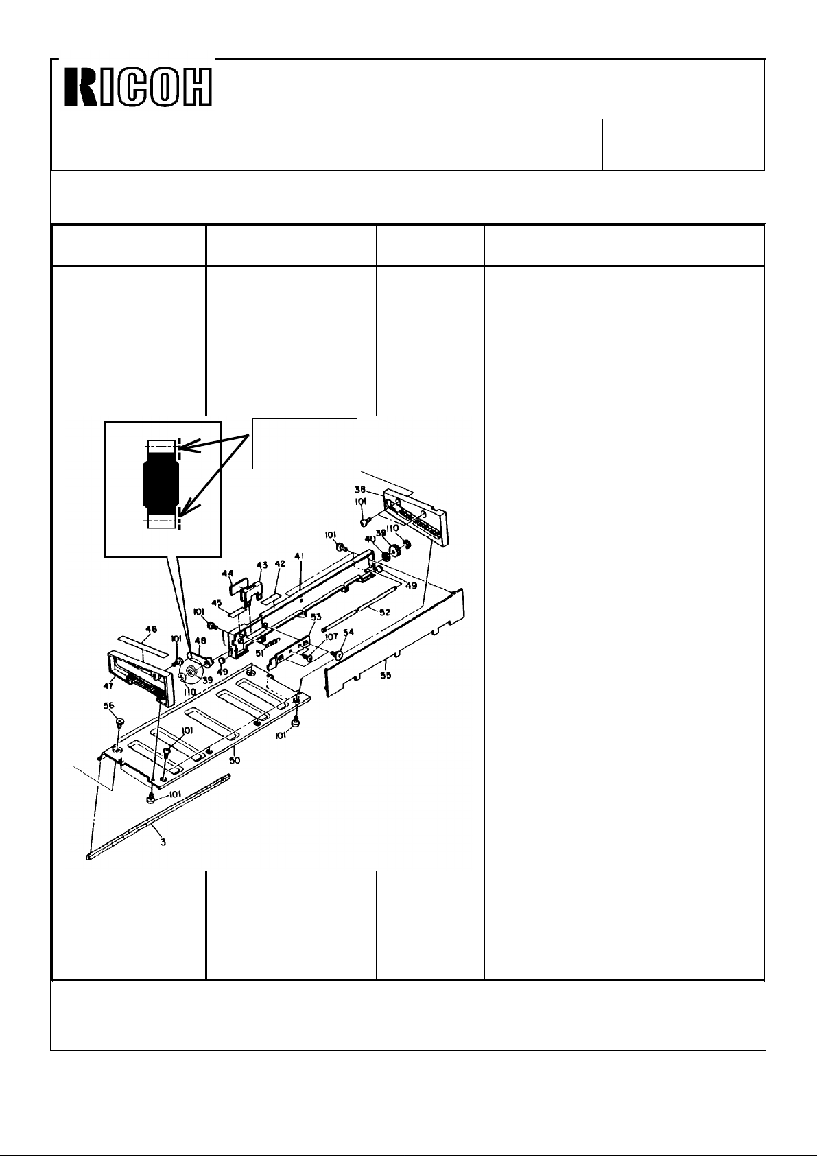
3. The machine detects an 81/2" x
13" original when the original length
sensor is activated by the gear on
the front of the original stopper
(A0287907). To ensure this, the side
of the gear, which is detected by
the sensor, must be painted white
(see illustration in the left). This has
been applied from the March ’92
production. Therefore, this
procedure is required for the 5
machines of the February ’92
production or when the gear is
replaced with a service part.
The silicone oil sensor
(P/N-52055258) and sensor bushing
(P/N-5446 4278) are required. (They
have been installed from the March
’92 production machines.)
Page 3
Technical Bulletin No. RTB-001
SUBJECT: Software Modification (No. 1) DATE: June 30, ’92
PAGE: 3 of 3
Item of New
Functions
Exit Tray Copy
Limit
Duplex Side
Fence Width
Adjustment
Description Necessary
Modification
The number of the
exit tray copy limit
can be selected from
300, 350, 400, or "no
limit" using service
tool 2-15 (initial
setting: 300).
The initial setting for
the duplex side fence
width (service tool
5-02) is changed
from 0 mm to -0.6
mm. This allows
adjustment of the
fence width not only
in the narrower
direction, but also in
the wider direction in
the field. (It can be
made 0.6 mm wider
from the production
setting.) The
adjustable range is
still the same (0 to
-1.8 mm in 0.6 mm
steps).
Modified
Item No. 1
and 2 in
Table 1
Modified
Item No. 3 in
Table1
Note
Even when "no limit" is selected,
"Remove copies from the copy tray"
is also displayed without stopping
the copy run.
NOTE: 1. If only the operation ROM board is replaced with the new type:
* The [A4] and [81/2" x 13"] keys will be displayed in user tool no. 3, but they
cannot be pressed.
* The [300], [350], [400], and [No] keys for the exit tray copy limit are displayed in
service tool 2-15, but only the [300] key can be pressed.
2. If only the ADF main control board is replaced with the new type, the machine
will stop the operation when an 81/2" x 13" original is used. To recover that
condition, the main switch must be turned off then on.
3. If only the ADF main control board is the old type, 81/2" x 13" originals cannot
be detected.
4. If only the paper feed control board is the old type, the duplex side fence width
for 81/2" x 13" paper cannot be adjusted by service tool 5-02.
Page 4
Technical Bulletin No. RTB-002
SUBJECT: Software Modification (No. 2) DATE: Sep. 15, ’92
PAGE: 1 of 7
PREPARED BY: H. Kokubo
CHECKED BY:
CLASSIFICATION:
Action Required
Troubleshooting
Retrofit Information
To enable the use of the A372 sorter stapler, the ROMs on the operation ROM board and
main board have been changed as shown in table 1. This modification has been applied
from the July ’92 production machines. The differences between the sorter version
software (old ROMs) and sorter stapler version software (new ROMs) are listed in table 2.
NOTE: 1. The ROMs (10 pieces for the operation ROM board and 6 pieces for the main
board) must be replaced as a set.
2. The new ROMs completely cover all functions of the sorter version machine.
Therefore, the ROMs for the sorter version machine will no longer be supplied as
service parts. (NRG ITS had already received 2 sets of the master ROMs.)
3. The old and new operation ROM board and main board are interchangeable
with one another (interchangeability o/o) for the A458 sorter version machines.
(The old PCBs can still be used for the A458 sorter version machines.)
Revision of service manual
Information only
Other
FROM: Copier Technical Support Section
MODEL:
F5 (NRG 25101)
Table 1: Modified Items
Modified
PCB
Operation
ROM Board
(Operation
Panel Ass’y)
Main Board A0285091 A0288802 IC210 A0285093 A0288850 83A9
Old Part
Number
A0285242
(AG011286)
New Part
Number
A0288803
(A0288800)
IC Number
(Printed on
the PCB)
IC201 A0285290 A0288900 5619
IC202 A0285291 A0288901 0BB7
IC205 A0285292 A0288902 F7C6
IC206 A0285293 A0288903 76BB
IC203 A0285294 A0288904 4FBC
IC204 A0285295 A0288905 1909
IC207 A0285296 A0288906 ECEF
IC208 A0285297 A0288907 644D
IC210 A0285298 A0288908 527D
IC211 A0285299 A0288909 6CC2
IC198 A0285094 A0288851 2A4E
IC205 A0285095 A0288852 D0E9
IC190 A0285096 A0288853 ED4D
IC123 A0285097 A0288854 52BF
IC124 A0285098 A0288855 D124
Old ROM
Part
Number
New ROM
Part
Number
Total
Check
Sum
Page 5
Technical Bulletin No. RTB-002
SUBJECT: Software Modification (No. 2) DATE: Sep. 15, ’92
PAGE: 2 of 7
Table 2: Description of New Functions
Item of New
Functions
Access to the
sorter stapler
Access to the
special features
User Tools See table 3 on page 5.
Service Tools See table 4 on page 5.
New Service Call
Status Codes
Beeper for SC82 The beeper sounds
Description Note
The A372 sorter
stapler is accessible.
The special features
(cover mode,
chaptering mode,
and paper designate
mode) can be used.
SC95 for the first
sorter, SC96 for the
second sorter, and
SC97 for the third
sorter are displayed
as a communication
error between the
copier and sorter
staplers.
when SC82
(operation unit
transmission error) is
displayed.
Both systems for the sorter and sorter stapler can
be used by changing the setting of utility 12-5-8
(default: sorter stapler system). For details, refer to
the accompanying table of "New Utility Modes."
For the details of the sorter stapler operation, refer
to page 53 and 108 through 111 of the operating
instructions.
The special features can be used only with the
sorter stapler system. For details, refer to page 64
of the operating instructions.
If SC82 is displayed, there is a possibility of CPU
malfunction and of the machine going out of
control. The beeper sound instructs the customer
to turn off the main switch or to call the service
representative.
SC82 can be displayed forcibly, by disconnecting
the optical fiber cable connector between the
operation unit and main board.
Page 6
Technical Bulletin No. RTB-002
SUBJECT: Software Modification (No. 2) DATE: Sep. 15, ’92
PAGE: 3 of 7
NOTE: 1. To ensure the paper is squared in the sorter stapler bins, the copying speed is
reduced to 80.8 cpm (only for B5, A4, 81/2"x11", 81/2x"13", and 81/2"x14" sizes
paper) when copies are continuously fed to the same bin. The copy modes in
which this happens are as follows:
Copy Modes that the Copy Speed is Reduced
Original
Set
ADF Sort and 1-sided original to
ADF Sort and 2-sided original to
Exposure
glass
Exposure
glass
Exposure
glass
Exposure
glass
SADF Stack and 1-sided original to
SADF Stack and 1-sided originals to
ADF Stack and 1-sided original to
ADF Stack and 1-sided originals to
ADF Stack and 2-sided original to
ADF Stack and 2-sided original to
Copy Mode Copy Set
1-sided copy mode
2-sided copy mode
Stack and 1-sided original to
1-sided copy mode
Stack and 1-sided originals to
2-sided copy mode
Stack and 2-sided original to
2-sided copy mode
Stack and 2-sided original to
1-sided copies mode
1-sided copy mode
2-sided copy mode
1-sided copy mode
2-sided copy mode
2-sided copy mode
1-sided copies mode
Note
Number
1
1
2 or more
2 or more The speed of front side
copying is 101 cpm.
2 or more The speed of front side
copying is 101 cpm.
2 or more
2 or more
2 or more The speed of front side
copying is 101 cpm.
1 or more
1 or more When the copy set number
is 4 or more, the speed of
front side copying is 101
cpm.
1 or more When the copy set number
is 4 or more, the speed of
front side copying is 101
cpm.
1 or more
Page 7
Technical Bulletin No. RTB-002
SUBJECT: Software Modification (No. 2) DATE: Sep. 15, ’92
PAGE: 4 of 7
2. Copying speed with the ADF mode varies depending on paper and original
sizes as shown below:
Paper Size Original Size Copying
Speed (cpm)
B5, A4, 81/2"x11",
81/2"x13",
81/2"x14"
B4 B5, A4, 81/2"x11",
A3, 11"x17" All sizes 61
B5, A4, 81/2"x11",
81/2"x13",
81/2"x14"
B4 81(101) The copying speed is 101 cpm
A3, 11"x17" 61(101) The copying speed is 101 cpm
81/2"x13",
81/2"x14", B4
A3, 11"x17" 61(81) The copying speed is 101 cpm
101
81
Note
when the copy set number is 4
or more. However, one copy is
skipped each time the original is
exchanged.
when the copy set number is 3
or more. However, one copy is
skipped each time the original is
exchanged.
when the copy set number is 4
or more. However, one copy is
skipped each time the original is
exchanged.
Page 8
Technical Bulletin No. RTB-002
SUBJECT: Software Modification (No. 2) DATE: Sep. 15, ’92
PAGE: 5 of 7
Table 3: User Tools with the Sorter Stapler
Item (Menu No.) Description
Disable Display (6) The Staple key has been added in this screen.
By pressing this key, when more than the maximum copy number for
stapling (default: 50) is made in the sort mode, and the copies reach that
number, the copying is paused and the Manual Staple key is displayed.
This allows the use of the stapling function with the sort mode for
operators even when they forget to set the staple mode first. (This means
that the priority is given to the staple mode, not the sort mode.)
As an initial setting, copying in the sort mode is not paused even when
more than the maximum copy number for stapling is made. (The priority
of the sort mode.)
Disable Unit (7) The screen is the same as before. In the sorter stapler system, the 1st,
2nd, and 3rd sorter staplers (including the staple function) are disabled by
pressing the "Sorter 1", Sorter 2", and "Sorter 3" keys.
Table 4: Service Tools with the Sorter Stapler
Item (Menu No.) Description
Sorter Bin Copy Limit
(2-07)
Dual Sort (2-08) This function is not effective for the sorter stapler system. (In the
Set Initial Display (2-16) In addition, the auto staple mode can be set as an initial display. (The
Supply Yield/Forming
(3-04)
Utility (4-05) See table 5 on page 6.
Copies per bin in the stack mode can be limited in a range from 35 to
50. The same number is effective for the staple mode. (Default: 50)
Copies per bin in the sort mode can be limited in a range from 55 to
100. (Default: 70)
sorter stapler system, more than two sets of a sort or stack job can
be made without removing copies from bins.)
cover/chaptering modes are not possible.)
The number of the used staple is displayed separately for the 1st,
2nd and 3rd sorter staplers.
Page 9
Technical Bulletin No. RTB-002
SUBJECT: Software Modification (No. 2) DATE: Sep. 15, ’92
PAGE: 6 of 7
Table 5: New Utility Modes
Mode No.
Set No. of Mode No. 5
0 to 7 6-5-0 7-5-0 11-5-0 13-5-0
8 6-5-8 7-5-8 10-5-8 11-5-8 12-5-8 14-5-8
9 6-5-9 7-5-9 8-5-9 9-5-9 10-5-9 12-5-9 13-5-9 14-5-9
10
11
12
13
14
15
NOTE: The bold numbers in the table shows new or modified functions. Their descriptions
are as follows:
6-5-0: Automatic Sort Selection
The default has been changed to ON (the Automatic Sort Selection is effective).
6-5-9: A3 Double Copy Count
The mechanical copy counter counts up 2 when an A3 or 11"x17" size copy is made.
(Default: OFF, Double Count) The old software was for A3 (or 11"x17") double count only.
7-5-8: Automatic APS Selection•
The default has been changed to ON (the Automatic APS Selection is effective).
6 7 8 9 10 11 12 13 14
7-5-9: Pause Stapling
During stapling of copies in the bins, stapling can be paused by pressing the Clear/Stop
key. (Default: ON, the pause is effective)
8-5-9: Duplex Tray Maximum Limit
The maximum number of copies stacked in the duplex tray can be changed. ON: 50 for
A3, B4, 11"x17", and 81/2"x14" and 100 for A4, B5, 81/2"x11", and 81/2"x13". OFF: 40/80.
(Default: OFF)
9-5-9: Automatic Staple Mode Selection
The auto staple mode is automatically selected when the sort key is pressed. (Default:
OFF, not effective)
10-5-9: Valid 81/2"x13" Key
The 81/2"x13" and A4 keys are displayed in user tools no. 3 to select original and copy
paper sizes. (Default: ON, effective)
11-5-8: Fusing Rush Current Prevention
Rush current from the wall outlet is absorbed to prevent the circuit breaker for the wall
outlet from being blown. This must be always ON. (Default: ON, effective) There was the
same function with the old software, but the default setting has been changed.
Page 10

Technical Bulletin No. RTB-002
SUBJECT: Software Modification (No. 2) DATE: Sep. 15, ’92
PAGE: 7 of 7
12-5-8: Sorter/Sorter Stapler System Switching
The sorter or sorter stapler systems can be selected. (Default: ON, sorter stapler system)
12-5-9: Disable Cover/Chaptering Modes
The special features (cover/chaptering modes) are disabled. (Default: OFF, the modes are
effective) The special features are available only with the sorter stapler system.
13-5-9: Stapling with Stack Mode
Stapling with the stack mode is available. (Default: OFF, not effective) Stapling with the
stack mode is not possible when the sorter stack face up mode is selected by user tool
no. 8. (The staple position will be wrong in this mode.)
14-5-8: Valid Pre-heat Key
By holding on the Clear Modes key for a while, all displays on the operation unit turn off.
(Default: OFF, not effective)
14-5-9: Sort Copies in Reverse Order
When the sorter stack face up mode is selected with user tool no. 8, not only in the stack
mode, but also in the sort mode, copies are delivered to the bins with the face (image
side) up. This sorts copies in the reverse page order. (Default: OFF, not effective)
Page 11
Kmxml
SUBJECT: DC Harness Damage
Technical Bulletin
No.
RTB-003
DATE:
PAGE: 1 of 1
NOV.
30, ’92
PREPARED BY: H.
CHECKED BY: ,
CLASSIFICATION:
■
Action Required
❑
Troubleshooting
❑
Retrofit Information
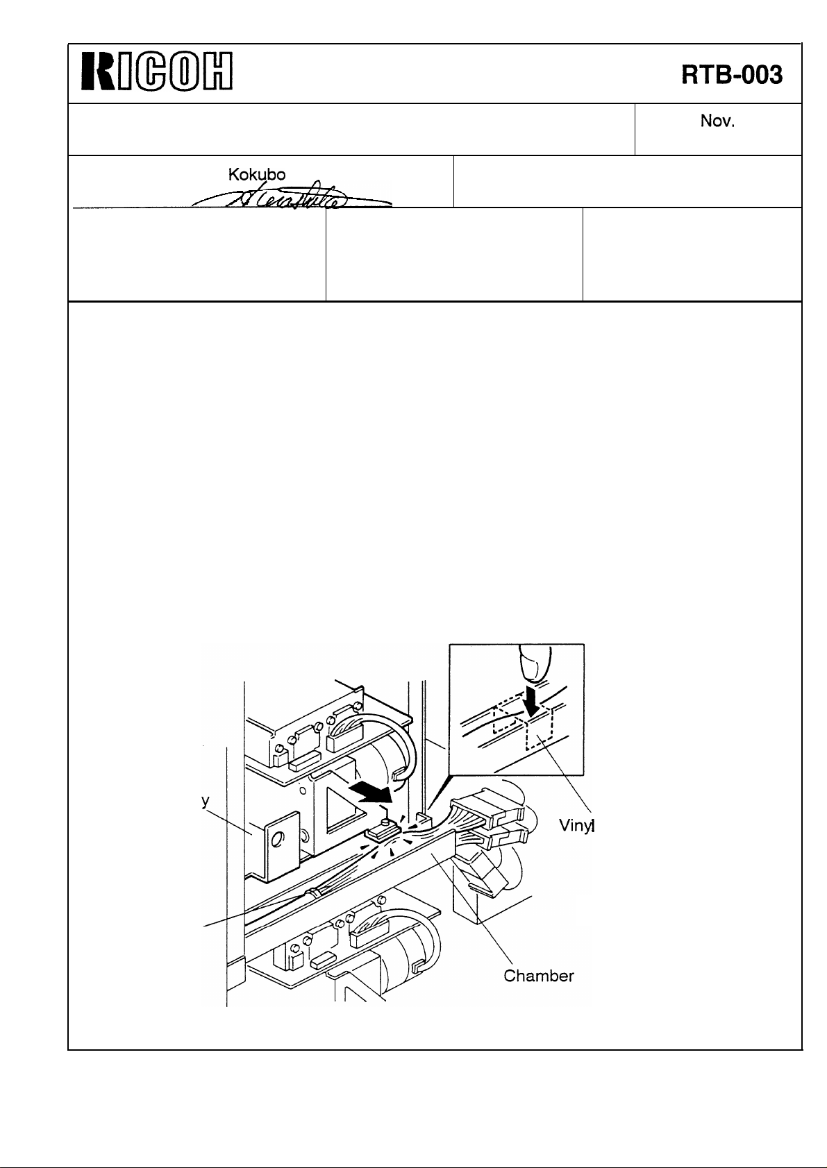
On the production line, it was found that the dc main harness was damaged.
The harness, which runs behind the 2nd paper tray, is cut as shown below when the 2nd
paper tray is slid in. If the harness is not run in the chamber properly and has slack, part
of the harness may come out the chamber and be damaged.
The harness is fitted in the chamber and secured with two bindings. However, this is not
sufficient because of variation in production. Since October 1992, this part has been
significantly checked during production to take away the slack in the harness.
[Action Required]
Kokubo
❑
Revision of service manual
❑
Information only
❑
Other
FROM: Copier Technical Support Section
MODEL:
F5 (NRG 25101)
At the installation of the machine, remove the right rear cover (2 screws), and check if the
harness is properly fitted in the chamber. If it is not, take up the slack in the harness and
secure the harness with a strip of vinyl tape or equivalent (see illustration below).
Rear of the
2nd Paper Tra
I
Tape
.
DC Main
Harness
Page 12
NNmMl
Technical Bulletin No. RTB-004
SUBJECT: DF Motor Shaft Breakage
PREPARED BY: H. Kokubo
CHECKED
CLASSIFICATION: MODEL:
■
Action Required
❑
Troubleshooting
❑
Retrofit Information
[Symptom]
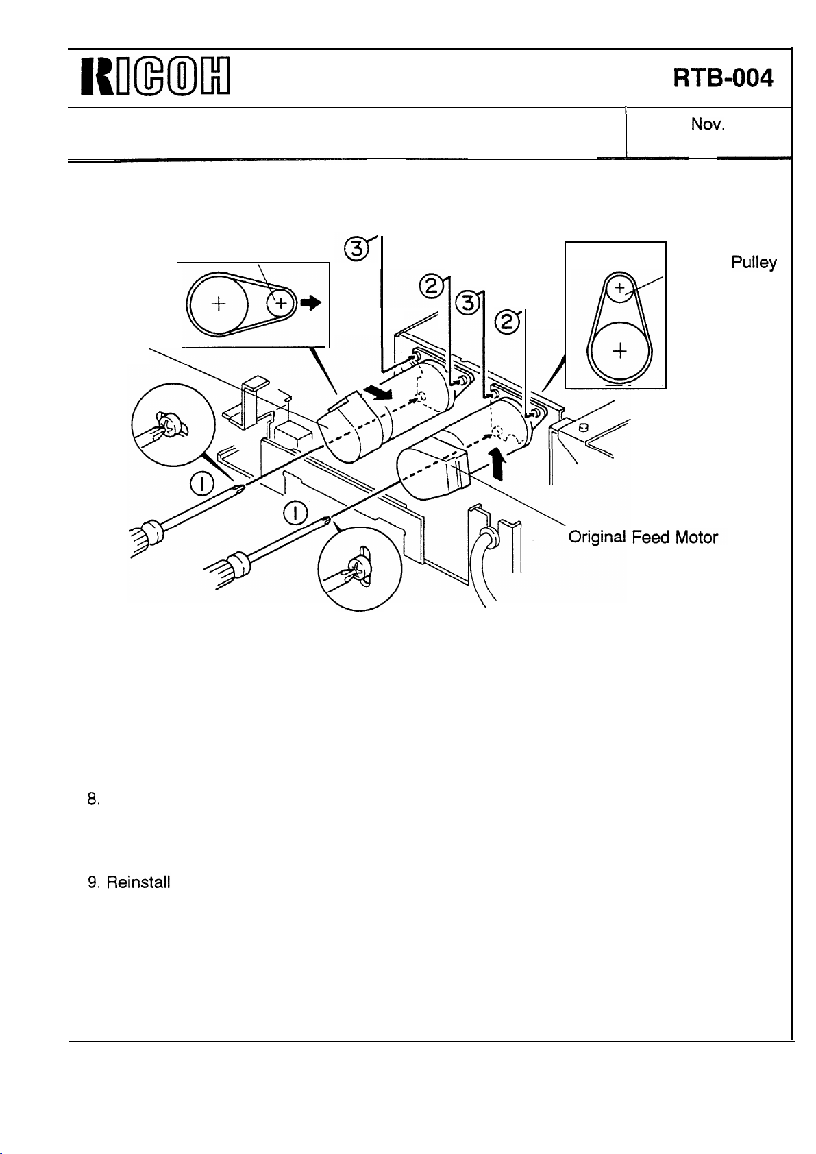
The shaft of the dc motors (P/N: AX06 0027) in the ADF (i.e. the original feed motor,
transport motor, and reverse motor) breaks.
[Cause]
The tension of the timing belts engaged with the motor’s pulleys is too strong.
BY:
❑
Revision of service manual
•l Information only
❑
Other
FROM: Copier Technical Support Section
F5 (NRG 25101)
DATE: NOV, 30, ’92
PAGE: 1 of 3
We have been using the same
similar problem has occurred. When the mass-production of the Gestetner version
machine started, the tension was increased. The shaft of the motor is not strong enough
for the existing belt tension, causing the shaft break.
[Solution]
Tension of the timing belts has been weakened from the July 1992 production machines
(from serial number of 6202070001).
There is possibility of the improper tension of the timing belts in the following machines:
April, ’92 Production:
May, ’92 Production:
June, ’92 Production:
For the machines listed above, perform the procedure in the following pages at the
installation of the machines.
6202040001 (1 machine)
6202050001 to 6202050005 (5 machines)
6202060001 to 6202060004 (4 machines)
dc
motors for this model in our domestic market, but no
Page 13
Nlmml
Technical Bulletin
No.
RTB-004
SUBJECT: DF Motor Shaft Breakage
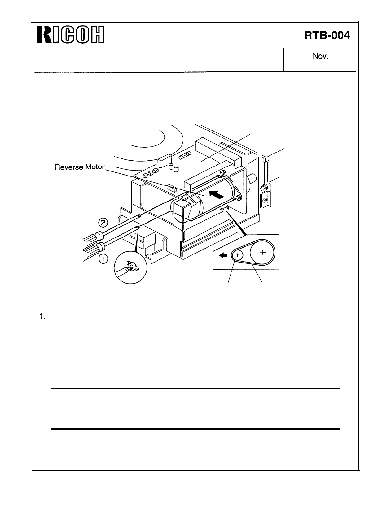
Motor Timing Belt Adjustment Procedure
Blower
/
DATE:
PAGE: 2 of 3
Control Board
NOV.
30, ’92
Motor Pulley
1.
Turn off the main switch and remove the ADF rear cover (7 screws).
2. Remove the blower control board.
3. Loosen the two screws securing the reverse motor.
4.
While firmly pushing the motor to the left, retighten the screws in the order described in
the illustration. Fully tighten the first screw before the second one. (The belt tension will be
proper even if the motor is strongly pushed to the left.)
.
Caution:
much tension will be applied. (When the second screw is tightened, the motor pulley
slightly moves, applying more tension to the timing belt. This will cause the motor
shaft to break.)
If the screws are tightened in a different order from the specified one, too
Timing Belt
I
Page 14
WHml
SUBJECT: DF Motor Shaft Breakage
Motor Pulley
Transport
Motor
Technical Bulletin
No.
1
RTB-004
DATE:
PAGE: 3 of 3
Nov.
Motor
30, ’92
5.
Remove the ADF control board.
6.
Loosen three screws each securing the transport motor and original feed motor,
7.
In the same way, retighten the screws as described in the illustration.
Check if the tension
8.
Note:
9.
Proper tension
sure the timing
all the removed
of each timing belt is proper.
can be obtained by following steps 4
belts do not slip on the pulleys when
parts.
and 7 only. At step 8, make
drive is applied.
Page 15
Technical Bulletin No. RTB-005
SUBJECT: Finisher Version Information DATE: July 15, ’93
PAGE: 1 of 23
PREPARED BY: H. Kokubo
CHECKED BY:
CLASSIFICATION:
Action Required
Troubleshooting
Retrofit Information
Revision of service manual
Information only
Other
FROM: Copier Technical Support Section
MODEL: F5
(Gestetner 25101/
Nashuatec 53101)
TABLE OF CONTENTS
1. UNIQUE FUNCTIONS OF THE FINISHER
VERSION MODEL 3
2. FUNCTIONAL DETAILS 3
2.1 COPY MODE 3
1. Simplex original to simplex copy mode ........................................ 4
2. Simplex originals to duplex copy mode ........................................ 4
3. Duplex original to duplex copy mode .......................................... 6
4. Duplex original to simplex copies mode ...................................... 6
2.2 ALTERNATE PAPER FEEDING TIMING CHART 7
2.3 ACCOUNTING MODES 10
1. How to e nter the c opy mod e .......... ........ .......... ........ ........ ........ ... 10
2. How to leave the copy mode in the accounting mode ................. 10
3. How to set the accounting modes ................................................. 10
4. How to enter the copy mode in the accounting mode
for servicing .................................................................................. 10
Page 16

Technical Bulletin No. RTB-005
SUBJECT: Finisher Version Information DATE: July 15, ’93
PAGE: 2 of 23
TABLE OF CONTENTS
2.4 COVER SHEET AND CHAPTERING MODES 11
1. How the copies are collated into sets in the duplex
copy mode with the cover or chaptering mode ............................ 11
2. How the designated original is copied in the duplex
original to duplex copy mode ........................................................ 12
2.5 DIFFERENCES IN MECHANISM BETWEEN
THE ADF AND RDH 13
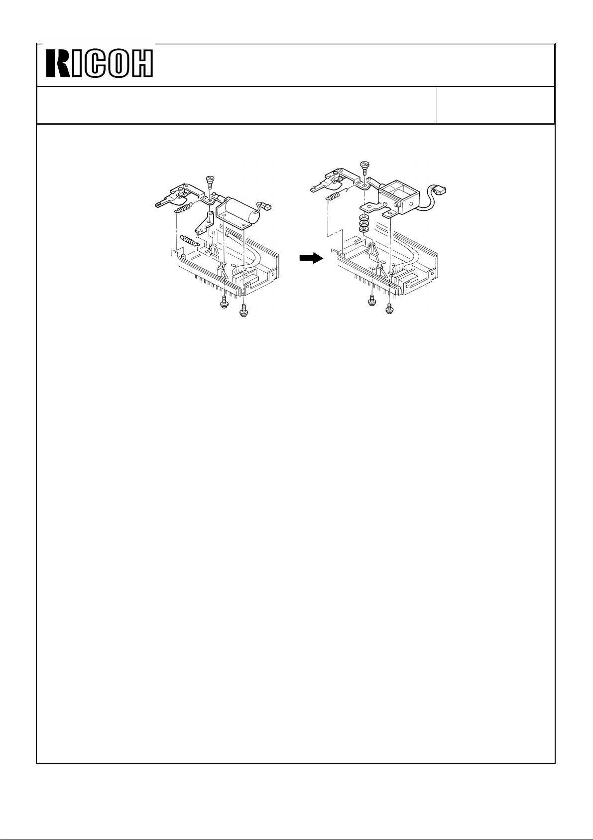
1. Recycle arm solenoid .................................................................... 13
2. Original transport drive motor ........................................................ 13
3. Instruction decal ............................................................................. 13
3. NEW SELF-DIAGNOSTICS FOR THE FINISHER 14
4. MAIN CONTROL BOARD DIP SWITCH SETTING 15
5. MEAN POWER CONSUMPTION DATA 16
6. USER TOOLS 17
1. User tools unique for the finisher version ..................................... 17
2. User utility table (user tool no. 10) ................................................ 18
7. SERVICE TOOLS 19
1. Service tools unique for the finisher version ................................. 19
2. Utility modes unique for the finisher version ................................. 21
3. Utility mode comparison table of the sorter,
sorter/stapler, and finisher ............................................................ 22
.
Page 17

Technical Bulletin No. RTB-005
SUBJECT: Finisher Version Information DATE: July 15, ’93
PAGE: 3 of 23
1. UNIQUE FUNCTIONS OF THE FINISHER VERSION MODEL
The major differences between the sorter version and finisher version of the F5 are
as follows:
1. Permits the installation of the optional finisher (with the original recirculating
motion of the RDH).
2. Permits the installation of the optional key counter bracket and printer connector
unit.
3. New or modified user and service tools.
4. Advanced cover and chaptering modes.
5. Enables the use of the normal accounting mode and of the security accounting
mode.
6. Satisfies the German electromagnetic field interference standard (VDE 243).
2. FUNCTIONAL DETAILS
2.1 COPY MODES
There are two copy modes: sort and stack. In the stack mode copies of the same
page are grouped together. When this mode is selected with user tool number 10,
the originals set in the stack original feed table of the RDH are copied just like with
the sorter or sorter/stapler version machine. The originals are fed and returned to
the table just once (ADF mode).
On the other hand, in the sort mode the copies are assembled as sets in
sequential order. This mode is always selected when originals are set in the stack
feed table of the RDH, except when the stack mode is selected. In this mode, the
RDH performs the original recirculating motion (RDH mode).
The following explains the differences in original and copy paper motions when
simplex or duplex copies are made from the simplex or duplex originals in the sort
mode:
Page 18

Technical Bulletin No. RTB-005
SUBJECT: Finisher Version Information DATE: July 15, ’93
PAGE: 4 of 23
1. Simplex original to simplex copy mode
One original feeding cycle makes one set of copies. To make more sets of copies,
originals recirculate in the RDH accordingly. (Copies are always collated into sets.)
When copy delivery to the finisher is selected, the copies are inverted in the
finisher in order to stack the copies with the image side down on the shift tray. The
copies are stacked in page order.
When one original is set in the stack original feed table, the original is recirculated
once, as usual. Then, the machine detects that only one original has been set.
The original is again fed from the table, then the machine enters the original
non-recirculating mode (ADF mode) to complete copying. The original stays on the
exposure glass until the copy run finishes.
2. Simplex originals to duplex copy mode
In case of the other RDH and finisher systems, usually two cycles of the simplex
original feeding makes one set of duplex copies. The first cycle of the original
feeding is to make copies of the odd pages of originals. The copies are stacked in
the duplex tray. Then, for the second original feeding, the even pages of originals
are copied onto the reverse sides of the copies from the duplex tray. This motion
is repeated until all the desired sets of copies are completed.
For this copier, the alternate paper feeding system is used to speed up the
simplex to duplex copy job. The first original feeding is just like the other RDH and
finisher systems. The odd pages of originals are copied and the copies are
stacked in the duplex tray. However, the second original feeding and the following
steps are different.
Unlike the other RDH and finisher systems, from the second original feeding, both
the odd and even pages of originals are copied in one original feeding cycle. (This
means that originals are copied in sequential order.) The alternate paper feeding
system allows this.
When the odd page of originals is copied, paper is fed from the normal paper tray.
The copy is stacked in the duplex tray. When the next original (the even page of
originals) is copied, the copy, which was made and stacked in the duplex tray
during the previous cycle of the original feeding, is fed from the duplex tray. The
original image is copied onto the reverse side of the copy then the copy is
delivered. The copier repeats feeding the paper from the normal paper tray and
from the duplex tray alternately. This is called the alternate paper feeding. For
more details, refer to the "Alternate Paper Feeding Timing Chart".
The copier repeats the above motion until the desired sets of copies are
completed. (During the final original feeding cycle, only the even pages of originals
are copied and all the copies in the duplex tray are fed out.) As a result, the copier
can complete the copy job in the same number of original feeding cycles as the
desired number of copies, plus one. On the other hand, in the other RDH and
finisher systems, the original feeding cycle is repeated twice the desired number of
copy sets.
Page 19

Technical Bulletin No. RTB-005
SUBJECT: Finisher Version Information DATE: July 15, ’93
PAGE: 5 of 23
The duplex copies are automatically delivered to the finisher shift tray, not to the
copier copy tray. The copies are stacked in page order on the tray without the
inversion of copies unlike the simplex original to simplex copy mode.
NOTE: When the simplex originals to duplex copy mode is selected, if a margin of 15 mm
or more is entered in the margin adjustment mode, the copying speed is set at 61
cpm, whatever size of original or copy paper is used. Copies are made using the
OPC segment for A3 size copy. (The images of 3 originals are produced for one
rotation of the OPC belt.) If the difference in the selected margin between the front
and reverse side of the copy image is 15 mm or greater, e.g. 5 mm margin at the
left on the front side and 10 mm margin at the right on the reverse side, the
copying speed is also set at 61 cpm.
This is because the originals copied on the front and reverse side are alternately
copied due to the alternate paper feeding system. As the margin can be adjusted
by changing the original flash (exposing) timing, the original stop on the exposure
glass must correspond to the adjusted flash timing. (If a margin is created at the
left, the flash timing is advanced. If a margin is created at the right, it is delayed.)
When the margin is created on the front and rear of copies separately, two
different flash timings alternate with each other. If the difference in the flash timing
between two originals becomes greater, i.e. 15 mm or more in the margin, the
original transportation cannot correspond to the alternate two different flash timings
due to the limit of the original transportation speed.
For example, if a margin is created at the left on the front side of copies, after an
original for which no margin is created, the original which has the margin must be
transported to the exposure glass faster than usual in order to catch up with the
advanced flash timing. If the margin is 15 mm or greater, the original cannot catch
up with the advanced flash timing.
This copier has one more copying speed: 81 cpm. However, this is not used in
case of a slow down in the margin adjustment mode. To enable 81 cpm, the copy
mode for B4 size paper (B4 size copy mode), where the images of 4 originals are
produced for one rotation of the OPC belt, must be used. In the A4 size copy
mode three originals are fed into the RDH from the stack original feed tray before
the first original is flashed. For the B4 size copy mode, it is two originals. Due to
this, the original transport speed in the B4 size copy mode is almost the same as
that in the A4 size copy mode, even though the copying speed of the B4 size copy
mode is 81 cpm. Therefore, even if A4 size copies are made using the B4 size
copy mode, there is not enough margin in the original transportation speed.
Page 20

Technical Bulletin No. RTB-005
SUBJECT: Finisher Version Information DATE: July 15, ’93
PAGE: 6 of 23
3. Duplex original to duplex copies mode
The front side of originals is copied during one cycle of original feeding. The
copies are stacked in the duplex tray. At the same time the originals are inverted
and returned onto the original table. Due to this, the reverse side of the originals is
copied during the next cycle of the original feeding. The images are copied on the
reverse side of the copies from the duplex tray and the duplex copies are
automatically delivered to the finisher shift tray, not to the copier copy tray. The
copies are stacked in page order on the tray without the inversion of copies as in
the simplex originals to duplex copy mode.
To make more sets of copies, the above motion is repeated. (Copies are always
collated into sets.) This means that the original feeding cycle is repeated twice the
desired number of copy sets.
4. Duplex original to simplex copies mode
One cycle of original feeding makes one set of copies. For each original feeding,
the front side image is copied and the copy is stacked in the duplex tray. Then the
original is inverted in the RDH and the reverse side image is copied onto the copy
from the duplex tray. After the images on both sides of the original are copied, the
original returns to the original table. To make more sets of copies, originals
recirculate in the RDH accordingly. (Copies are always collated into sets.)
When copy delivery to the finisher is selected, the copies are inverted in the
finisher in order to stack the copies with the image side down on the shift tray. The
copies are stacked in page order.
Page 21
Technical Bulletin No. RTB-005
SUBJECT: Finisher Version Information DATE: July 15, ’93
PAGE: 7 of 23
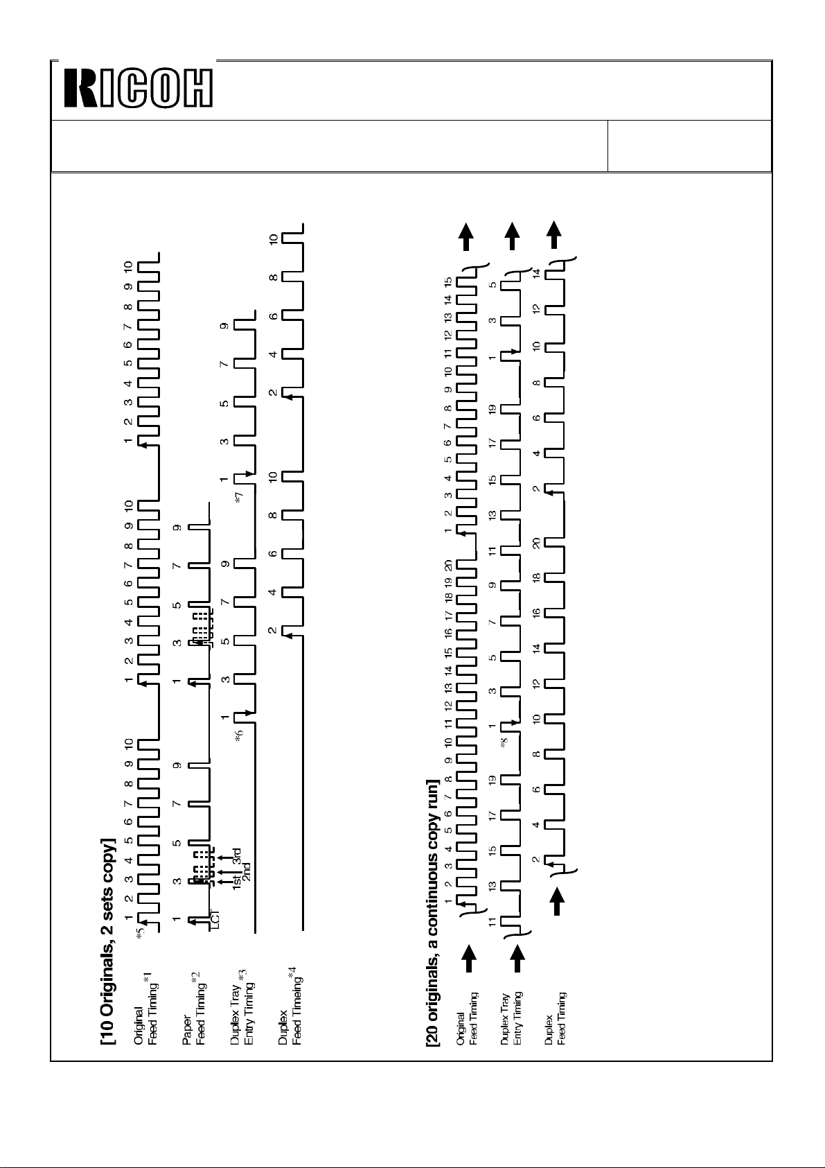
2.2 ALTERNATE PAPER FEEDING TIMING CHART
Page 22

Technical Bulletin No. RTB-005
SUBJECT: Finisher Version Information DATE: July 15, ’93
PAGE: 8 of 23
*1 to *8 on the charts in the previous page show the key points for understanding
the alternate paper feeding. Refer to the explanation below for each key point. The
timing charts are based in the following copy mode conditions:
Upper One: Two sets of copies are made from 10 originals in the simplex original
to duplex copy mode.
Lower One: A large number of copy sets are made from 20 originals in the
simplex original to duplex copy mode. The timing chart shows only part of the copy
run.
*1: "Original Feeding Timing" shows when each original feed starts from the stack
original feed table. The numbers 1 to 10 identify the originals. The chart means
that the 10 originals are recirculated three times.
*2: "Paper Feed Timing" shows the timing when each paper is fed from the LCT. The
numbers correspond to the number of the original which will be copied on the front
side of the paper.
The chart shows only odd number because the even numbered originals are
copied on the reverse side of the paper.
The paper feed start timing is different when paper is fed from the LCT, 1st tray,
2nd tray, and 3rd tray. This is because paper transportation takes more time
depending on where the paper feed starts and where images are transferred to the
paper. The time for the LCT is the longest and that for the 3rd tray is the shortest.
If the paper is fed from a station other than the LCT, the paper for the first original
starts being fed as shown in the dotted lines. The following paper feed intervals
are the same as that for the LCT.
*3: "Duplex Tray Entry Timing" shows when the paper activates the duplex entrance
junction sensor and is delivered to the duplex tray. The number on top of each
entry timing corresponds to the number of the original which has been copied on
the front side of the paper.
*4: "Duplex Feed Timing" shows when the paper for each original is fed from the
duplex tray. The number on top of each duplex feed timing correspond to the
number of the original which will be copied on the reverse side of the paper.
As the timing chart shows, during the first original feed cycle only the odd
numbered originals are copied onto the paper fed from the paper tray. During the
2nd cycle the odd numbered originals are copied as in the first cycle, and also
even numbered originals are copied onto the paper fed from the duplex tray.
Copying for the front and reverse sides is done alternately in this period. (This is
the alternate paper feeding.) For the 3rd original feed cycle (i.e. the last original
feed cycle) only the even numbered originals are copied onto the paper from the
duplex tray, completing the copy run (two sets of five duplex copies are completed).
Page 23

Technical Bulletin No. RTB-005
SUBJECT: Finisher Version Information DATE: July 15, ’93
PAGE: 9 of 23
*5: When the LCT is used the original to be copied starts being fed from the stack
original feed table and the paper for it starts being fed from the LCT right away.
During the first original feeding cycle, the 2nd original (and also the following even
numbered originals) is just fed and returned without being copied. During the 2nd
cycle, all originals are copied. Finally during the last original feed cycle, only the
even numbered originals are copied.
*6: The copy of the first original enters the duplex tray just after the 10th (last) original
starts being fed and before the first original starts being fed for the 2nd feed cycle.
This duplex tray entry timing for the first copy does not depend on the paper being
fed from the LCT, first tray, 2nd tray, or 3rd tray. This is because the time for the
paper to enter the duplex tray after images are transferred to the paper is constant
no matter where paper is fed from.
Just after the 3rd paper has entered the duplex tray, the paper which first entered
in the duplex tray starts being fed from the duplex tray in order to match with the
copying for the 2nd original during the 2nd feeding cycle.
*7:‘ The 2nd copy of the first original enters the duplex tray just before the first original
starts being fed for the last original feed cycle. When this happens, the last copy in
the duplex tray just starts being fed. This means that
a) when the first copy made during the next original feed cycle enters
the duplex tray and
b) if the number of originals is 10 or less (as in this case) then
c) the duplex tray is empty even in the alternate paper feeding motion.
*8: The lower timing chart shows simplex original to duplex copying using 20 originals.
There are copies remaining in the duplex tray (approximately 6 copies in this case)
when the first copy made during the next original feed cycle enters the duplex tray.
This chart also shows that the copy of the first original enters the duplex tray just
after the 10th original starts being fed, as in the upper timing chart.
Page 24

Technical Bulletin No. RTB-005
SUBJECT: Finisher Version Information DATE: July 15, ’93
PAGE: 10 of 23
2.3 ACCOUNTING MODES
There are two types of accounting mode: security accounting mode and (normal)
accounting mode. In the normal accounting mode, all of the operators can use the
user access code mode in user tool number 9. In the security accounting mode,
only key operators whose user access codes are registered by their service
representative can use all the user access code mode. (For the user access code
mode, refer to the operating instructions.)
1. How to enter the copy mode in the accounting mode
Enter one of user access codes by pressing the Number keys.
2. How to leave the copy mode in the accounting mode
Press the Clear/Stop key while pressing the Clear Modes key.
3. How to set the accounting modes
1. Normal Accounting Mode
Press the "Access Code" key in service tool 2-08. Then enter appropriate user
access codes with user tool number 9.
2. Security Accounting Mode
(1) Be sure that the "Free Use" key is selected with service tool 2-08. Then enter
an appropriate user access code with user tool number 9. The user access codes
entered in this condition will be the codes for the key operator.
(2) Press the "Access Code/Super User Mode" key with service tool 2-08. Then
return to the normal screen.
(3) Enter appropriate user access codes with user tool number 9. This will be the
codes for normal operator.
4. How to enter the copy mode in the accounting mode for servicing
The accounting mode is canceled when DIP switch 101- 2 on the main control
board is ON. Note that DIP switch 101-2 is commonly used to enable accessing
the service tool password "999900." DIP switch 101, 102, and 103 on the main
control board must be kept at the initial setting, except 101-1 and 101-2 which
have the same functions as the sorter and sorter stapler versions.
CAUTION: When the main control board is replaced with a new one, all data in
user tool number 9 must be cleared in order to reset RAM on the main control
board and start up the use of the user access code mode. (This is the same as
the data in service tools 3-01 to 3-07. All data must be cleared when the main
control board is replaced.)
Page 25

Technical Bulletin No. RTB-005
SUBJECT: Finisher Version Information DATE: July 15, ’93
PAGE: 11 of 23
2.4 COVER SHEET AND CHAPTERING MODES
The following are different from the cover sheet and chaptering modes of the
sorter stapler version model. They are features unique to the finisher version
model.
1. With user tool number 8 " Select Special Tray," the 1st paper tray can be
designated as only for the cover sheet, and one of the 1st, 2nd and 3rd paper tray
can be designated as only for the slip sheet for the chaptering mode. Two paper
trays can be designated separately for the cover and slip sheets at the same time.
When no paper tray is designated, the paper in the 1st paper tray is automatically
used for the cover and slip sheets, just like in the sorter stapler version model.
2. In the chaptering mode with the simplex originals to duplex copies mode, the
original designated as the first page of each chapter is automatically copied onto
the front side of the copy. For example, when the 4th original is designated, the
reverse side of the 2nd copy will be blank and the 4th original is copied onto the
front side of the 3rd copy.
In this mode, users can select to have the designated original copied onto special
paper (slip sheet) or normal paper.
3. When the back cover is selected in the cover mode, it can be selected with user
tool number 10 "User Utility/Reverse Back Cover Sheet." In this case, the setting
decides if the image of the back cover faces inside of the copy set (normal) or
outside.
4. In the chaptering mode, up to 15 originals can be designated by pressing the
"Next" key, although for the sorter stapler version model, up to 10 can be.
5. Even in the duplex copy mode, the copy for the original which is designated as
the cover and slip sheets does not enter the duplex tray. This is to enable the use
of copy paper up to 163 g/m2 of paper weight. It is usually up to 120 g/m2 for
duplex copies. Therefore, the cover and slip sheets have images only on one side.
Refer to the following explanation for understanding how this is done. (In the
chaptering mode with the simplex originals to duplex copies mode, if the copy for
the designated original to normal paper is selected, the copy will enter the duplex
tray and have images on both sides as usual.)
1. How the copies are collated into sets in the duplex copy mode with the
cover or chaptering mode
In the simplex originals to duplex copy mode, the original next to the designated
one is copied on the front of the copy next to the cover or slip sheet, resulting in
having the reverse side of the cover and slip sheets blank. In the duplex original to
duplex copy mode, the reverse side of the designated original is not copied,
resulting in having the reverse side of the cover and slip sheets blank. (Therefore,
the reverse side of the designated original should be blank.)
Page 26
Technical Bulletin No. RTB-005
SUBJECT: Finisher Version Information DATE: July 15, ’93
PAGE: 12 of 23
In the simplex or duplex original to duplex copy mode, the duplex copies are
automatically delivered to the finisher shift tray, not to the copier copy tray. The
copies are stacked in page order on the shift tray without being inverted. However,
as the copy image on the cover and slip sheets is made while the reverse side
copies are made, in order not to enter the cover and slip sheets into the duplex
tray, only the cover and slip sheets are inverted in the finisher to stack all copies in
page order.
2. How the designated original is copied in the duplex original to duplex
copy mode
In the duplex original to duplex copy mode, although the original designated with
the cover or chaptering mode is always copied on the front side of the cover or slip
sheet, it is copied during the second original feeding cycle, not during the first one.
This is because the cover or slip sheet must enter the duplex tray if the designated
original is copied during the first original feeding cycle. To allow this, the original
recirculating motion in this mode is different from that in the duplex original to
duplex copy mode without the cover or chaptering mode, as follows:
1. During the 1st Original Feeding Cycle: The front side of the originals set in the
RDH is copied as usual. However, the designated original is not copied during this
cycle. Before the designated original feeds out to the stack feed table, it is not
inverted. As a result, the front side (image side) of the designated original only
faces the direction of the reverse side of the other originals and stacked in the
stack feed table.
2. During the 2nd and the Following Original Feeding Cycle: During the 2nd cycle,
the reverse side of the originals is copied. The designated original is copied during
this cycle. The completed duplex copies are delivered to the shift tray. As the copy
image on the cover or slip sheet is made while the reverse side of the other
originals is copied, only the cover or slip sheet is inverted in the finisher to stack all
copies in page order.
For the following cycles, both sides of the originals, including the designated
original, are copied as usual in the duplex original to duplex copy mode until all the
desired copy sets complete. Even during this period, only the cover or slip sheet is
inverted in the finisher to stack all copies in page order.
3. During the Last Original Feeding Cycle: After completing the copy run, one more
original feeding is done. This is to return the designated original, which had been
made side down during the first original feeding cycle, into the original setting.
(The designated original is inverted before it feeds out to the stack feed tray, and
the other originals are not.)
As a result, the original feeding is twice the desired number of copy sets plus, one.
Page 27
Technical Bulletin No. RTB-005
SUBJECT: Finisher Version Information DATE: July 15, ’93
PAGE: 13 of 23
2.5 DIFFERENCES IN MECHANISM BETWEEN THE ADF AND RDH
[ADF Type]
1. Recycle Arm Solenoid
The ADF feeds originals just once for each copy job. On the other hand, the RDH
recirculates originals according to the desired copy set number. Due to this, in the
RDH, the recycle arm is repeatedly placed on the original stack and repeatedly
returned for each copy set. If the existing type of the solenoid is used, it will
malfunction due to heat generated by the repeated on and off operation.
To cope with this, a new solenoid has been used to operate the recycle arm. It is a
two-way solenoid, which is the same as the one used for the finisher junction gate,
and once the position of the solenoid plunger is changed according to the signal
from the CPU, this solenoid keeps its position until a different signal is generated.
This works using a permanent magnet installed in the solenoid.
2. Original Transport Drive Motor
[RDH Type]
There are three dc motors (#AX060027) to drive the original transport rollers. In
the RDH, the motors have been changed to more durable ones. There is a groove
for an E-ring in the shaft of the existing motor, but the motor for the RDH
(#59365501) does not have such a groove.
3. Instruction Decal
There is a decal (#AA000114), which instructs how originals are set, in the stack
original feed table. There is no problem with the ADF system, but it has been
found that electrostatic charges are generated in the decal due to the recirculating
motion of originals. As a result, the bottom original stacked in the original table
tends to stick to the decal and misfeed.
To cope with this situation, the decal has been moved to the right end of the
original table cover.
Page 28
Technical Bulletin No. RTB-005
SUBJECT: Finisher Version Information DATE: July 15, ’93
PAGE: 14 of 23
3. NEW SELF-DIAGNOSTICS FOR THE FINISHER
The following Error reset status codes have been added for the finisher
self-diagnostics:
NOTE: There are two types of self-diagnostics: one is "Service call" and the other is "Error
reset." A Service call occurs when a problem that may cause serious damage to
the machine is detected.
Classification
Finisher SC93 Wait/busy
Status
Code
SC94 Signal
SC95 Motor drive
SC96 Motor drive
SC97 Motor drive
Item Symptom Possible Cause Remarks
signal error
transmission
error from
the finisher
error 1
error 2
error 3
A wait or busy
signal from the
finisher stays
generated for more
than 25 seconds.
After the copier CPU
sends a status
request signal to the
finisher, there is no
response signal
from the finisher for
more than 10
seconds.
A status that the
finisher cannot
make copies in both
shift tray and staple
modes due to a
defective motor is
detected.
A status that the
finisher cannot
make copies in shift
tray mode due to a
defective shift motor
is detected.
A status that the
finisher cannot
make copies in
staple mode due to
a defective motor is
detected.
Defective finisher or
inverter control board.
Optics fiber cable
disconnected, or
defective copier main,
finisher, or inverter
control board.
Defective inverter or
finisher transport
motor, shift tray lift
motor, exit drive
motor, stopper drive
motor, or their related
sensor.
Defective shift motor
or shift tray half turn
sensor.
Defective jogger,
stapler drive, staple,
stack feed-out, or
inverter stopper drive
motor, or their related
sensor.
Service call
indication
appears in
the
operation
display
when these
symptoms
are
detected.
Page 29
Technical Bulletin No. RTB-005
SUBJECT: Finisher Version Information DATE: July 15, ’93
PAGE: 15 of 23
4. MAIN CONTROL BOARD DIP SWITCH SETTING
As the main control board has been changed, the new one has three dipswitches.
Each function is as follows:
Dipswitch No. Function at ON Function at OFF
Allows the use of the service
DPS101-1
DPS101-2
DPS101-3 Not used. Not used. OFF
DPS102-1
DPS102-2 Not used. Not used. OFF
DPS102-3 Not used. Not used. OFF
DPS103-1
DPS103-2
DPS103-3 Not used. Not used. OFF
tool access code which is
entered with service tool "1-02."
1) Allows the use of the initial
service tool access code: 99900.
2) Allows the operation of the
copier without entering any user
codes, even in the normal and
security accounting modes.
Japanese version (destination
identification).
Production use only. (Must be
ON.)
Production use only. (Must be
OFF)
Disables the service tool access
code which is entered with service
tool "1-02. "
1) Disables the initial service tool
access code: 99900.
2) Allows the selection of the
normal and security accounting
modes with service tool "2-08."
Overseas version. ON
Production use only. (Must be ON.) ON
Production use only. (Must be
OFF)
Default
Setting
OFF
OFF
OFF
Page 30
Technical Bulletin No. RTB-005
SUBJECT: Finisher Version Information DATE: July 15, ’93
PAGE: 16 of 23
5. MEAN POWER CONSUMPTION DATA
Mean Power Consumption
Copier only Copier + LCT Copier + LCT + Finisher
During copying
During warm-up
During stand-by
(Fusing Lamp OFF)
Main switch OFF
(During first 30min.)
Main switch OFF
(After 30 min.)
3.10 kW (380 V)
3.27 kW (400 V)
3.43 kW (415 V)
2.32 kW (380 V)
2.46 kW (400 V)
2.61 kW (415 V)
0.25 kW (380 V)
0.25 kW (400 V)
0.25 kW (415 V)
0.11 kW (380 V)
0.12 kW (400 V)
0.13 kW (415 V)
0.07 kW (380 V)
0.07 kW (400 V)
0.07 kW (415 V)
3.12 kW (380 V)
3.28 kW (400 V)
3.44 kW (415 V)
2.33 kW (380 V)
2.48 kW (400 V)
2.62 kW (415 V)
0.26 kW (380 V)
0.26 kW (400 V)
0.26 kW (415 V)
0.11 kW (380 V)
0.12 kW (400 V)
0.13 kW (415 V)
0.07 kW (380 V)
0.07 kW (400 V)
0.07 kW (415 V)
3.45 kW (380 V)
3.60 kW (400 V)
3.70 kW (415 V)
2.40 kW (380 V)
2.55 kW (400 V)
2.69 kW (415 V)
0.32 kW (380 V)
0.32 kW (400 V)
0.32 kW (415 V)
0.11 kW (380 V)
0.12 kW (400 V)
0.13 kW (415 V)
0.07 kW (380 V)
0.07 kW (400 V)
0.07 kW (415 V)
NOTE: The mean power consumption data for the "Copier only" and "Copier +
LCT" are the same as those of the sorter version machine.
Page 31

Technical Bulletin No. RTB-005
SUBJECT: Finisher Version Information DATE: July 15, ’93
PAGE: 17 of 23
6. USER TOOLS
The following are the new user tools for the finisher version model:
1. User Tools Unique for the Finisher Version
Item
(Menu No.)
Disable
Display
(6)
Disable Unit
(7)
Select
Special
Tray
(8)
User
Access
Code
(9)
Description
1) The option installation (system setup) function has been moved to service tool
1-08.
2) The "Staple" key used for the sorter stapler version model has been removed.
3) The other functions are the same.
A "Finisher" key for disabling the finisher has been added instead of the "Sorter
1 to 3" keys.
The 1st paper tray can be designated as only for cover sheets. One of the 1st,
2nd, and 3rd paper trays can be separately designated as only for slip sheets.
The designated paper tray will also have the same features as the special tray
that is set with service tool 2-12.
Menu number 8 "Sorter Stack Face Up/Down" used in the sorter stapler version
has been removed. (The "Select face up/down in stack mode" has been added
to user tool number 10 "User Utility" instead.)
When the accounting mode (the "access code" key) or security accounting mode
(the "Access Code/Super User Mode" key) is selected with service tool 2-08, the
following are available with this function:
1) Up to 500 user codes can be registered.
2) The registered user codes can be changed or deleted.
3) The number of copies made using each user code can be displayed. The data
can also be printed if the optional printer and printer connector unit are installed.
NOTE: The DIP switch setting (the printer side) is different from that for the
F200. The data bit length for the F200 is 7-bit, and that for the F5 is 8-bit.
4) When the security accounting mode is selected, selected only key operators
can use the above features. Other operators can only check the number of
copies made using their own user codes.
User Utility
(10)
For understanding how to use this mode, refer to the operating instructions.
Some functions in the service tools have become available in the user tools. In
addition, some new functions have been added. For details, refer to the "User
Utility Table" below.
Page 32

Technical Bulletin No. RTB-005
SUBJECT: Finisher Version Information DATE: July 15, ’93
PAGE: 18 of 23
2. User Utility Table (User Tool No. 10)
Item Description
Select the finisher mode The sort or stack mode can be selected. (Default: Sort)
Staple in stack mode Stapling with the stack mode is available. (Default: No, not
effective) This function is the same as service tool utility (4-05)
13-5-9.
Auto tray switching This function is the same as service tool 2-10. The title has been
changed from "Limitless Paper Feed." (Default: Yes, the default has
been changed from that for the sorter stapler version.)
3-side full image copy A new key, beside the Check modes key, to select the 3-side full
image copy mode can be used. This function is the same as
service tool utility (4-05) 7-5-0. The title has been changed from
"No Erase Copy." (Default: No)
The 3-side full image mode is selected at power on when "Yes" is
selected with service tool 2-09 "3-side Full Image"
Select count up or down
mode
Display the number of
originals
Exit originals to tray A new key, beside the Check modes key, to select the original tray
Select face up/down in
stack mode
Reverse back cover sheet This is a new function. When the back cover is selected in the
Copy onto slip sheets This is a new function. When copies are made in the chaptering
NOTE: For functions which can be set with both the user utility and service tools, if the
data is changed with one, the data in the other will be changed automatically.
Adding each copy or subtracting each copy for the copy number
counter can be selected. This function is the same as service tool
2-01. (Default: Up)
The number of originals copied in the stack original feed mode is
displayed in the message area after copying. This function is the
same as service tool 2-11 "Original Count Display." (Default: No)
exit mode can be used. This function is the same as service tool
utility (4-05) 4-1. (Default: No)
Copies made in the stack mode can be delivered face up (image
side up) to the shift tray. This function is the same as user tool
number 8 "Sorter Stack Face Up/Down" used in the sorter stapler
version. (Default: No)
cover mode, users can select to have the image of the back cover
face inside of the copy set or outside. (Default: Yes, It faces
outside.)
mode, users can be select to have the image of the designated
original copied on the slip sheet or not. (Default: Yes)
Page 33

Technical Bulletin No. RTB-005
SUBJECT: Finisher Version Information DATE: July 15, ’93
PAGE: 19 of 23
7. SERVICE TOOLS
The following are the new service tools for the finisher version model:
1. Service Tools Unique for the Finisher Version
Item
(Menu No.)
1 System Set-up
Option
Installation
(1-08)
2 User Functions
Maximum
Copy Number
(2-06)
Staple Copy
Limit
(2-07)
Free/User
Access Code
Operation
(2-08)
3 Data Logging
Duplex/
Finishing
Copies (3-02)
Supply
Yield/Forming
(3-04)
RDH/Finisher
Misfeeds
(3-06)
The option installation (system setup) function, which is in user tool number 6
"Disable display" for the sorter stapler version, has been moved.
To install the LCT, finisher, and key counter, this function must be used.
The maximum copy set number can be changed within a range of 1 to 9999.
(Default: 9999)
The selection of the maximum copy set number for the sort mode has been
removed because this is only for the ADF and sorter system.
The maximum staple capacity in the staple mode can be changed within a
range of 40 to 50 sheets. (Default: 50)
The "sorter bin copy limit" function used in this position of the sorter and sorter
stapler versions has been removed.
This is a new function. The accounting mode and security accounting mode can
be set. Press the "Access Code" key for the accounting mode and the "Access
Code/Super User Mode" key for the security accounting mode. Press "Free
Use" key to cancel these mode. (Default: Free Use) For the accounting and
security accounting modes, refer to the "2.2 ACCOUNTING MODES."
The "dual sort" function used in this position of the sorter and sorter stapler
versions has been removed.
The number of sheets entered into the finisher is displayed by paper size,
instead of that for the sorter. The number of the sheet entered into the duplex
tray is also displayed as in the sorter and sorter stapler versions.
In addition, the number of used staple is displayed. (In sorter stapler version, it
was displayed separately for the 1st, 2nd, and 3rd sorters.)
Paper misfeeds in the finisher is accumulated and displayed by location and
type: Inverter On Check, Inverter Off Check, and Finisher On check, instead of
that for the sorter. Original misfeeds in the RDH is also accumulated and
displayed as in the sorter and sorter stapler versions.
Description
Page 34

Technical Bulletin No. RTB-005
SUBJECT: Finisher Version Information DATE: July 15, ’93
PAGE: 20 of 23
Item
(Menu No.)
4 Process Control
Utility
(4-05)
5 System Test
Set Staple
Position
(5-07)
6 Print Out
(6)
Description
Some new functions have been added. For details, refer to the "Utility Modes
Unique for the Finisher Version" below.
This is a new function. The staple positions on the copy paper can be
adjusted by following the instructions on the screen.
This is a new function. The following data can be printed If the optional
printer and printer connector unit are installed.
NOTE:
(1) A printer with a standard RS232C interface is required. Use the printer
with functions as follows:
Mode: Asynchronous
Data format: Start/Stop/Data bit: 1 bit each
Data bit length: 8 bits
Parity permission: With
Parity setting: Even parity
Baud rate setting: 1,200 bps
Connector: 25 pins, D-connector
(2) If a Seiko printer DPU-411 is used, the dip switch settings are as follows
(note that the setting of DIP02 SW1 is different from that for the F200. The
data bit length for the F200 is 7 bits, and that for the F5 is 8 bits):
SW1 to 8 of DIP01: OFF/OFF/OFF/ON/ON/OFF/ON/ON
SW1 to 6 of DIP02: ON/OFF/OFF/OFF/ON/ON
(3) This function can be used without the optional printer connector unit if the
interface board (P/N A112 5060), harness between the interface board and
printer (P/N A531 5420), harness between the main control board and
interface board (P/N A112 7120), and 2 connector joint studs (P/N 1102
4139) are available, so that the printer can be connected to CN101 on the
main control board. The parts will be included in the copier from the June ’93
production. (For details, refer to MB no. 5.)
Process Control: Data for service tool 4-01 to 4-03.
Copies: Data for service tool 3-01 to 3-04.
Misfeeds: Data for service tool 3-05 and 3-06.
Service Ca lls: Data for service tool 3-07.
Operation Time: Data for service tool 3-08.
System Setup: Data for user tool no. 2, 3, 4, 6, 7, 8, 10, service tool 1-01 to
1-08, 2-01 t o 2-16, 4-04 , 4-05, 5- 02, 5-03 , 5-07.
All Items: All data for the above items.
Page 35

Technical Bulletin No. RTB-005
SUBJECT: Finisher Version Information DATE: July 15, ’93
PAGE: 21 of 23
2. Utility Modes Unique for the Finisher Version
Mode No.
Set No. of
Mode No. 5
0 to 7
8
9
10 6-5-10 7-5-10 8-5-10 9-5-10 11-5-10
11
12
13
14
15
NOTE: (1) "6-5-10" means that mode number 6, which can be turned ON or OFF, is ON
when mode number 5, which can be set at 0 to 15, is set at 10.
6 7 8 9 10 11 12 13 14
(2) The utility modes common with the sorter and sorter stapler versions are not
listed.
(3) Utility 2-10 "Duplex Speed-up Mode" is still valid when the stack mode, not sort
mode, is selected.
(4) Utility 1-8, 1-9, 2-8, 2-9, 7-5-9, and14-5-9 are not valid for the finisher version.
6-5-10: Automatic Staple Mode Selection
Users can select to have the auto staple mode (1 upper staple) or shift tray ON
mode selected when the Finishing key in the free operator screen is selected.
(Default: OFF, The shift tray ON mode is selected.)
7-5-10: Reverse Back Cover Sheet
This mode is the same as that in the user tool number 10 "User Utility."
8-5-10: Copy onto Slip Sheet
This mode is the same as that in the user tool number 10 "User Utility."
9-5-10: Manual Staple Mode
Enables the use of the manual staple mode when originals are set in the single
original feed mode or on the exposure glass. For understanding how to use the
manual staple mode, refer to the operating instructions. (Default: OFF, The manual
staple is not effective.)
11-5-10: Automatic Paper Feed Out in Manual Staple Mode
While copies are made in the manual staple mode, when this mode is selected
and the number of the copies stacked in the staple tray of the finisher exceeds the
stack capacity set with service tool 2-07, the copies are automatically fed out from
the jogger tray. (Default: OFF, This mode is not effective and the copies are
stacked in the jogger tray until the "#" key is pressed.)
Page 36

Technical Bulletin No. RTB-005
SUBJECT: Finisher Version Information DATE: July 15, ’93
PAGE: 22 of 23
3. Utility Mode Comparison Table of the Sorter, Sorter/Stapler, and Finisher Versions
Mode
No.
1
2
3 8 Paper Size Erase Mode 0 0 0
4 1 Original Tray Exit Mode 0 0 0
5
Set No. Mode Name
8 Original Count Indication
9
10
12
8 Continues Duplex Copying
9
10
0 SADF 50 cpm
1 SADF 34 cpm
2 SADF 25 cpm
3 SADF 20 cpm
Combination of "1-8" and
"1-10"
Disables Paper Near-end
Indication
Clears All Stored User
Programs
Combination of "2-8" and
"2-10"
Duplex Speed-up Mode
Default Setting for Each Mode No.
Sorter Sorter/Stapler Finisher
00
10 10
000
NOTE: "1-8"
and "1-9" are
not effective.
1) "2-8" and
"2-9" are not
effective in the
stack mode
0
10
NOTE:
effective.
2) "2-10" is
only.
Mode
No. (6
to 14)
6
7 No Erase Copy Mode OFF OFF OFF
8 Not used Must be OFF Must be OFF Must be OFF
9 Not used Must be OFF Must be OFF Must be OFF
10 Not used Must be OFF Must be OFF Must be OFF
11 Automatic Dual Sort Mode OFF Not valid Not valid
12 Not used Must be OFF Must be OFF Must be OFF
13
14 Not used Must be OFF Must be OFF Must be OFF
Setting
of
Mode
No. 5
0 to 7
Mode Name
Automatic Sort Selection ON ON OFF
Margin Adjustment Present
Memory
Default Setting for Each Mode No.
Sorter Sorter/Stapler Finisher
OFF OFF OFF
Page 37

Technical Bulletin No. RTB-005
SUBJECT: Finisher Version Information DATE: July 15, ’93
PAGE: 23 of 23
Mode
No. (6
to 14)
6
7 Automatic APS Selection ON ON ON
8 Not used Must be OFF Must be OFF Must be OFF
9 Not used Must be OFF Must be OFF Must be OFF
10 Disable Flash Life Notice OFF OFF OFF
11
12
13 Not used Must be OFF Must be OFF Must be OFF
14 Valid Pre-heat Key OFF OFF OFF
6
7 Pause Stapling Not valid ON Not valid
8
9
10 Valid 81/2"x13" key ON ON ON
11 Not used Must be OFF Must be OFF Must be OFF
12
13 Stapling with Stack mode Not valid OFF OFF
14
6
7 Reverse Back Cover Sheet Not valid Not valid ON
8 Copy onto Slip Sheet Not valid Not valid ON
9 Manual Staple Mode Not valid Not valid OFF
10 Not used Must be OFF Must be OFF Must be OFF
11
12 Not used Must be OFF Must be OFF Must be OFF
13 Not used Must be OFF Must be OFF Must be OFF
14 Not used Must be OFF Must be OFF Must be OFF
Setting
of
Mode
No. 5
8
9
10
Mode Name
Fusing Jam Indication OFF OFF OFF
Fusing Rush Current
Prevention
Sorter/Sorter-stapler System
Switching
A3 Double Copy Count OFF: Double
Duplex Tray Maximum Limit OFF: 40 (A3)/
Automatic Staple Mode
Selection
Disable Cover/Chaptering
Modes
Sort Copies in Reverse
Order
Automatic Staple Mode
Selection
Automatic Paper Feed Out
in Manual Staple Mode
ON ON ON
ON (Must be
OFF to use
the sorter)
Count Mode
80(A4)
Not valid OFF Not valid
Not valid OFF OFF
Not valid OFF Not valid
Not valid Not valid OFF
Not valid Not valid OFF
Default Setting for Each Mode No.
Sorter Sorter/Stapler Finisher
ON Not valid
OFF: Double
Count Mode
OFF: 40 (A3)/
80(A4)
OFF:Double
Count Mode
OFF: 40 (A3)/
80(A4)
Page 38

Technical Bulletin No. RTB-006
SUBJECT: Installation Procedure for Key Counter/Printer Connector
Bracket and Printer Connector Unit (Finisher Version Only)
PREPARED BY: H. Kokubo
CHECKED BY:
CLASSIFICATION:
Action Required
Troubleshooting
Retrofit Information
Revision of service manual
Information only
Other
FROM: Copier Technical Support Section
MODEL: F5
(Gestetner 25101/
Nashuatec 53101)
DATE: July 15, ’93
PAGE: 1 of 5
1. ACCESSORY CHECK
Check the quantity and condition of the accessories in the box according to the following
list.
Key Counter Bracket Accessory Check
1. Snap Bushing....................................................1
2. Wire Clamp .......................................................2
3. Philips Sunken Head Screw - M3 x 8 .............2
4. Philips Pan Head Screw - M4 x 8 ...................4
5. Philips Plated Screw - M4 x 8 .........................4
6. Grounding Screw with Star Washer ................2
7. Philips Plated Screw - M3 x 6 .........................2
8. Key Counter Hole Blind Cover ........................1
9. Key Counter Fixing Plate .................................1
10. Printer Connector Hole Blind Cover ................1
Printer Connector Unit Accessory Check
1. Grounding Screw with Star Washer ..................2
2. Philips Plated Screw - M4 x 8 ...........................1
3. Wire Clamp .........................................................1
CAUTION: The printer interface board (P/N A112 5060), printer harness (P/N
A531 5420), 2 connector joint studs (2 x P/N 1102 4039), and 4
nylon studs (4 x P/N 1105 0193), which are the copier’s
accessories, are required for the printer connector unit
installation.
Page 39

Technical Bulletin No. RTB-006
SUBJECT: Installation Procedure for Key Counter/Printer Connector
Bracket and Printer Connector Unit (Finisher Version Only)
2. INSTALLATION PROCEDURE
[A]
[D]
[B]
[C]
[D]
DATE: July 15, ’93
PAGE: 2 of 5
1. Remove the exterior cover [A] in the rear of the copy tray (3 screws). Then, remove
the two cover brackets [D] (2 screws each).
2. Install the key counter/printer connector bracket [C] with four M4x8 philips pan head
screws and one grounding screw [B] (accessories).
[A]
3. Install the snap bushing [A] (accessory) as shown.
4. Remove the copier rear right cover (2 screws).
5. Take the two connectors which are clamped behind the key counter/printer connector
bracket, then feed them through the hole in the bottom of the bracket as shown.
Page 40

Technical Bulletin No. RTB-006
SUBJECT: Installation Procedure for Key Counter/Printer Connector
Bracket and Printer Connector Unit (Finisher Version Only)
[A]
[E]
[C]
[D]
[B]
DATE: July 15, ’93
PAGE: 3 of 5
6. If an optional key counter is installed, install the key counter receptacle [A] with the
two M3x8 philips sunken head screws and key counter fixing plate [B] (accessories).
NOTE: The key counter must be one of the following:
- Hengstler
- Hecon
- Veeder Ro ot
7. Remove the shorting connector [E], then connect the connectors from the key counter
and copier.
8. Install the two wire clamps [D] (accessories) and clamp the harness as shown.
9. If the optional printer connector unit is not installed, install the printer connector
hole blind cover [C] with the two M3x6 philips plated screws (all are accessories).
Page 41

Technical Bulletin No. RTB-006
SUBJECT: Installation Procedure for Key Counter/Printer Connector
Bracket and Printer Connector Unit (Finisher Version Only)
[B]
[A]
[C]
[D]
[E]
[L]
[H]
[I]
[K]
[J]
DATE: July 15, ’93
PAGE: 4 of 5
[F]
[G]
10. If the optional printer connector unit [A] is installed, install it with the grounding
screw [K] and M4x8 philips plated screw (accessories).
11. Connect the connector [J] of the harness form the copier to the PCB on the printer
connector unit.
12. Install the 4 nylon studs [E], then the printer interface board [D]. Connect the connector
of the harness from the printer connector unit to the interface board.
13. Install the printer harness [G] with the two connector joint studs [L].
NOTE: The printer interface board (P/N A112 5060), printer harness (P/N A531 5420),
2 connector joint studs (2 x P/N 1102 4039), and 4 nylon studs (4 x P/N 1105
0193), which are copier accessories, are required for the printer connector unit
installation.
14. Connect the other end of the printer harness to the connector on the printer interface
board.
15. Fix the grounding wire with the grounding screw [D] (accessory). Then, install the wire
clamp [F] (accessory) then clamp the printer harness with the clamp as shown.
16. If an optional key counter is not installed, install the key counter hole blind cover
[H] with the two M3x8 philips sunken head screws and key counter fixing plate [I]
(accessories).
Page 42

Technical Bulletin No. RTB-006
SUBJECT: Installation Procedure for Key Counter/Printer Connector
Bracket and Printer Connector Unit (Finisher Version Only)
[A]
[B]
17. Install the key counter/printer connector bracket cover [A] with the grounding screw [B]
and the 4 M4x8 philips plated screws (accessories).
DATE: July 15, ’93
PAGE: 5 of 5
NOTE: If the optional printer connector is installed, a printer with a standard RS232C
interface is required. Use a printer with the following functions:
Mode: Asynchronous
Data format: Start/Stop/Data: 1 bit each
Data bit length: 8 bits
Parity permission: With
Parity setting: Even parity
Baud rate setting: 1,200 bps
Connector: 25 pins, D-connector
Page 43

Technical Bulletin No. RTB-007
SUBJECT: Sorter Stapler Installation with Finisher Version Copier DATE: Sep. 30, ’93
PAGE: 1 of 4
PREPARED BY: H. Kokubo
CHECKED BY: T. Ito
CLASSIFICATION:
Action Required
Troubleshooting
Retrofit Information
This bulletin is to inform you of how to modify the copier when the sorter stapler or sorter
(F5 sorter version copier’s options) is installed with the F5 finisher version copier.
The table below shows all items to be modified:
Item To Be Modified Necessary Part Modification Procedure
All EPROMs on the operation
control board
All EPROMs on the main
board
DIP switch setting of the main
board
Short connector position on
the main board
10 ROMs. Refer to "ROM
Conversion Table" for details.
6 ROMs. Refer to "ROM
Conversion Table" for details.
None Turn OFF
None Disconnect the two short
Revision of service manual
Information only
Other
FROM: Copier Technical Support Section
MODEL: F5
Finisher Version Only
(nashuatec 53101)
Refer to Fig. 1 for the location
of each ROM.
Refer to Fig. 2 for the location
of each ROM. Fig.3 shows
necessary cautions when
replacing the ROMs.
DPS103-1
DPS103-2
connectors for
JP103
position. Then, set them to the
"512 KB" positions (see Fig.
5). This allows the use of the
512 k-byte ROMs, instead of 1
M-byte ROMs.
(see Fig. 4).
JP102
from the "1 MB"
and ON
and
Page 44

Technical Bulletin No. RTB-007
M3
M1
M2
M0
S1 S0
IC124 IC123
IC190
IC198
IC205
IC210
SUBJECT: Sorter Stapler Installation with Finisher Version Copier DATE: Sep. 30, ’93
PAGE: 2 of 4
ROM Conversion Table
ROM Location
Operation ROM
Board
Main Board
ROM Name
(See Fig. 1 & 2)
1E IC201 A0288900 A1125205
1O IC202 A0288901 A1125206
2E IC205 A0288902 A1125207
2O IC206 A0288903 A1125208
3E IC203 A0288904 A1125209
3O IC204 A0288905 A1125210
4E IC207 A0288906 A1125211
4O IC208 A0288907 A1125212
5E IC210 A0288908 A1125213
5O IC211 A0288909 A1125214
M0 IC210 A0288850 A1125102
M1 IC198 A0288851 A1125103
M2 IC205 A0288852 A1125104
M3 IC190 A0288853 A1125105
S0 IC123 A0288854 A1125108
S1 IC124 A0288855 A1125109
IC Number
(Printed on PCB)
Part # for
Sorter Version
Part # for
Finisher Version
Fig. 1 Operation ROM Board
IC201
1E
1O
3E
3O
IC202
IC203
IC204
4E
4O
IC207
IC208
2E
2O
IC205
IC206
5E
IC210
5O
IC211
Fig. 2 Main Board
Page 45

Technical Bulletin No. RTB-007
SUBJECT: Sorter Stapler Installation with Finisher Version Copier DATE: Sep. 30, ’93
PAGE: 3 of 4
Fig. 3 ROM Replacement
Replacement Instructions
Replace all 6 EPROMs on the main board with the ones for the sorter stapler version
machine. Be careful that the 4 EPROMs (M0, M1, M2, and M3) for the finisher version are
1 M-byte EPROMs, but those for the sorter stapler version are 512 k-byte ones.
When setting the 512 k-byte EPROM in the socket, be sure align the right end of the
EPROM with the right end of the socket as show above. The 4 holes of the left end of the
socket will be empty holes.
Page 46

Technical Bulletin No. RTB-007
SUBJECT: Sorter Stapler Installation with Finisher Version Copier DATE: Sep. 30, ’93
PAGE: 4 of 4
Fig. 4 DIP Switch Po sition
Fig. 5 Short Connector Position
Page 47

Technical Bulletin No. RTB-008
SUBJECT: Fuser Oil Overflow DATE: Feb. 15, ’94
PAGE: 1 of 1
PREPARED BY: H. Kokubo
CHECKED BY: S. Hamano
CLASSIFICATION:
Action Required
Troubleshooting
Retrofit Information
Even when the oil path is cleaned at every PM visit as described in the service manual,
fuser oil might overflow from the oil receiver (in the main body side).
If inside of the oil tube going to the oil tank (P/N-A0284904) becomes very dirty, the tube
might clog and oil might overflow from the oil receiver.
If the oil does not pass through smoothly, replace the tube with a new one. At the same
time, clean or replace the oil tank with a new one to prevent dirty oil from generating
circulating.
If paper generating a lot of paper dust is used, it is recommended to replace the tube and
oil tank every 1,000,000 copies.
Revision of service manual
Information only
Other
FROM: 2nd Technical Support Section
MODEL: F5
(Gestetner 25101/
nashuatec 53101)
Page 48

Technical Bulletin No. RTB-009
SUBJECT: Additional SC Status Code DATE: Feb. 15, ’94
PAGE: 1 of 1
PREPARED BY: H. Kokubo
CHECKED BY: S. Hamano
CLASSIFICATION:
Action Required
Troubleshooting
Retrofit Information
SC55, which has been used from the first mass production, is missing in "8. TABLES FOR
SELF-DIAGNOSTICS" of the field service manual. Add the following information to the
manual:
Classification
Imaging process
Status Code
SC55
Item
OPC motor drive error at OPC cleaning mode
Revision of service manual
Information only
Other
FROM: 2nd Technical Support Section
MODEL: F5
(Gestetner 25101/
nashuatec 53101)
Symptom
During the OPC cleaning operation, no encoder pulse is produced from the OPC motor.
The OPC cleaning is stopped and the copier enters the copy standby condition. At the
next power ON, the OPC cleaning is tried again and the same procedure is repeated.
Possible Cause
Overload of the OPC motor due to an abnormal operation of the OPC cleaning brush
roller, defective OPC motor, or defective main/OPC motor drive board.
Remarks
Even when this condition is detected, Error reset #55 is not displayed. However, the status
code is recorded in the logging data of the service tools.
Page 49

Technical Bulletin No. RTB-010
3 mm
SUBJECT: Timing Belt Tension Adjustment Standards DATE: Feb. 15, ’94
PAGE: 1 of 3
PREPARED BY: H. Kokubo
FROM: 2nd Technical Support Section
CHECKED BY: S. Hamano
CLASSIFICATION:
Action Required
Troubleshooting
Retrofit Information
Revision of service manual
Information only
Other
MODEL: F5
(Gestetner 25101/
nashuatec 53101)
The following is the timing belt tension adjustment standards which are not described in
the service manual:
Vertical paper transport drive belt tension standard
3 mm defl ecti on a t 140 ± 90 g pressure.
100 mm
Duplex jogger and back fence drive belt tension standards
• Back fence belt
3 mm defl ecti on a t 20 ± 10 g pressure.
140 ± 90 g
3 mm
20 ± 10 g
Page 50

Technical Bulletin No. RTB-010
Main motor
pulley
SUBJECT: Timing Belt Tension Adjustment Standards DATE: Feb. 15, ’94
PAGE: 2 of 3
• Side fence (jogger) belt
6.5 mm de flec tion at 20 ± 10 g pressure.
6.5 mm
20 ± 10 g
Duplex/exit unit drive belt
2.8 mm de flec tion at 22 7 ± 35 g pressure.
Main motor belt tension standard
8 mm defl ecti on a t 1.2 ± 0.25 kg pressur e.
227 ± 35 g
2.8 mm
1.2 ± 0.25 kg
8 mm
Page 51

Technical Bulletin No. RTB-010
7 mm
SUBJECT: Timing Belt Tension Adjustment Standards DATE: Feb. 15, ’94
PAGE: 3 of 3
Main drive belt tension standard
7 mm defl ecti on a t 1.2 ± 0.25 kg pressure.
1.2 ± 0.25 kg
Main motor belt alignment standard
41.5 ± 1.2 mm from the copier rear frame at the two locations
shown.
Main drive belt alignment standard
Between 83.7 and 81.1 mm from the copier rear frame at the
two locati ons show n.
41.5 ±
1.2 mm
Copier rear frame
83.7 ∼ 81.1 mm
Copier rear frame
Page 52

Technical Bulletin No. RTB-011
SUBJECT: Checking the Cleaning and Scavenging Bias DATE: Feb. 15, ’94
PAGE: 1 of 3
PREPARED BY: H. Kokubo
CHECKED BY: S. Hamano
CLASSIFICATION:
Action Required
Troubleshooting
Retrofit Information
Revision of service manual
Information only
Other
Theory
A constant current cleaning power pack is
used. –20µA for the cleaning roller bias and
–10µA for the scavenging roller bias are
applied. The larger negative bias for the
scavenging roller attracts the positively
charged toner from the cleaning roller to the
scavenging roller.
To make the cleaning roller bias constant, a
varistor is used. The bias is approximately
–83 volts, and excessive current is
discharged through the varistor.
FROM: 2nd Technical Support Section
MODEL: F5
(Gestetner 25101/
nashuatec 53101)
Varistor
As the cleaning carrier wears out, the electrical resistance of the carrier increases.
Because a constant current power pack is used, the scavenging roller bias increases. If
the carrier is new, the scavenging roller bias is approximately –340 volts. (If the varistor is
removed, the cleaning roller bias is approximately –170 volts.)
For the cleaning roller bias, if the varistor is not used and the cleaning carrier wears out,
too much bias voltage will be applied to the toner collected by the cleaning roller. Because
a high negative voltage is applied to the positively charged toner, the collected toner on
the cleaning roller might be re-attracted to the OPC surface which is given a positive
charge by the PCC. This will appear on copies, especially on the leading edge, as a faint
dirty background. The varistor prevents this.
NOTE
If the copy volume is extremely low and if often only a few copies are made from an
original, the period of the main motor rotation for each copy becomes longer. This motor
also drives the cleaning unit and the cleaning carrier wears out faster than usual. In such a
case, no cleaning bias voltage is applied around the end of the cleaning carrier life time
(400,000 copies) because all current is discharged through the varistor due to too high
resistance of the carrier. As a result, a dirty background appears on copies.
If this occurs, replace the cleaning carrier with new one earlier than usual. Otherwise,
remove the varistor from the cleaning unit. For such a low copy volume customer, the
toner re-attraction to the OPC does not occur even without the varistor.
Page 53

Technical Bulletin No. RTB-011
Cleaning
power pack
VR
SUBJECT: Checking the Cleaning and Scavenging Bias DATE: Feb. 15, ’94
PAGE: 2 of 3
Checking the cleaning and scavenging bias
Pull out the cleaning unit.
Remove the varistor.
NOTE
Although the cleaning power pack is a
constant current type, the varistor makes the
bias voltage to the cleaning roller constant.
Removing the varistor allows for adjusting the
amperage.
Varistor
Remove the rear left cover and set an ammeter to the cleaning power pack as shown.
NOTE
To measure the cleaning roller side,
disconnect the wire from the "CL" terminal
CL S
(indicated on the power pack). Then, set an
ammeter between the wire connector and
A
terminal. To measure the scavenging roller
side, use the "S" terminal.
WARNING
A
Ammeter
When the main switch is ON, never touch
anything inside the rear left cover to avoid
possible injuries.
Turn on the main switch. After the copier enters the stand-by condition, access the service
tools.
Select [5-04] "I/O Test". Press the "Motor" key, then press the "Main" and "OPC" keys.
Press the "Lamp/Sol" key, then press the "QL" key.
NOTE
This procedure is necessary to avoid OPC deterioration.
Page 54

Technical Bulletin No. RTB-011
SUBJECT: Checking the Cleaning and Scavenging Bias DATE: Feb. 15, ’94
PAGE: 3 of 3
Press the "P. Pack 2" key, then press the "Cleaning Bias" key to measure the amperage.
It must be –20 ± 0.5 µA.
Set an ammeter to the "S" terminal side, then press the "Scav. Bias" key. The amperage
must be –10 ± 0.5 µA.
If the values do not meet the standards, adjust the amperage by turning the VR above
each terminal.
Standards
Cleaning Bias
Scavenging Bias
–20 ± 0.5 µA
–10 ± 0.5 µA
Scavenging
roller
Carrier (R1)
Cleaning roller
Carrier
NOTE
When both the "Cleaning Bias" and "Scav.
Bias" keys are ON, both amperages become
–10 µA. Therefore, if the cleaning bias is
measured while in a copy run, be sure to
disconnect the scavenging bias terminal from
the power pack.
SW1 in the middle figure to the right
represents the "Scav. Bias" key and SW2
represents the "Cleaning Bias" key.
Ammeter
SW1
A1
R2
OPC
SW2
A2
Cleaning
power pack
20µA – 10µA = 10µA
10µA
A1
10µA
A2
20µA
When both SW1 and
SW2 are turned on.
R1
R2
Page 55

Technical Bulletin No. RTB-012
SUBJECT: Operating Cautions for 11" x 181/2" and 14" x 81/2" Originals DATE: Feb. 15, ’94
PAGE: 1 of 1
PREPARED BY: H. Kokubo
CHECKED BY: S. Hamano
CLASSIFICATION:
Action Required
Troubleshooting
Retrofit Information
When inch size originals are used, make a
slot as shown to stop the original stopper at
the 81/2 inch position.
CAUTION
When the slot is made, operating cautions
must be instructed to operators, so that
operators can adjust the original stopper
position correctly according to the original
size set in the ADF. The A4 position and
81/2 inch position are very close. If the
original stopper position is not proper,
original misfeeds will occur.
Revision of service manual
Information only
Other
FROM: 2nd Technical Support Section
MODEL: F5
(Gestetner 25101/
nashuatec 53101)
Original stopper
Page 56

Technical Bulletin No. RTB-013
SUBJECT: Fuse Table DATE: Feb. 15, ’94
PAGE: 1 of 2
PREPARED BY: H. Kokubo
FROM: 2nd Technical Support Section
CHECKED BY: S. Hamano
CLASSIFICATION:
Action Required
Troubleshooting
Retrofit Information
Revision of service manual
Information only
Other
MODEL: F5
(Gestetner 25101/
nashuatec 53101)
The fuses used in the F5 are as follows:
FUSE TALE
Location Specification Connection Part number Notes
DC power supply unit
DC power supply unit
DC power supply unit
Flash power supply unit 6.3A/250V (EU)
ADF DC power supply unit
Paper feed DC power supply
unit
Development DC power
supply unit
DC motor drive board (FU401) 3.15A/250V (EU)
DC motor drive board (FU403) 3.15A/250V (EU)
DC motor drive board (FU404) 3.15A/250V (EU)
DC motor drive board (FU402) 1A /250V (EU)
Main/OPC motor drive board 8A/125V CN3-3 11070393 Main motor drive
Main/OPC motor drive board 1.6A/250V (EU)
Duplex blower drive board 3.15A/250V (EU)
Varistor board 3.15A/250V (EU)
ADF control board (RDH) 5A/250V (EU)
Blower control board (RDH) 3.15A/250V (EU)
6.3A/250V CN1-3
4A/250V CN2-2
6.3A/250V CN3-3
6A/250V (NA)
6.3A/250V CN1-3
4A/250V CN1-3 —
4A/250V CN1-3 —
3.15A/125V (NA)
3.15A/125V (NA)
3.15A/125V (NA)
1A/125V (NA)
2A/125V (NA)
4A/125V (NA)
3A/250V (NA)
5A/125V (NA)
4A/125V (NA)
CN1-3
CN406-2
CN406-1
CN406-3
CN406-4
CN4-2
CN1-6
—
CN104-3
CN1-6
11070673 (EU)
11070753 (NA)
— (EU)
11070751 (NA)
11070673 (EU)
11070753 (NA)
11070281 (EU)
— (NA)
11070673 (EU)
— (NA)
11070355 (EU)
11070354 (NA)
11070355 (EU)
11070354 (NA)
11070355 (EU)
11070354 (NA)
11070452 (EU)
11070386 (NA)
— (EU)
11070388 (NA)
11070355 (EU)
11070390 (NA)
11070672 (EU)
11070596 (NA)
11070752 (EU)
11070391 (NA)
11070355 (EU)
11070390 (NA)
AC power source IN
DC 5V OUT
(Each photo-sensor and eraser
drive)
AC power source IN
AC power source IN
AC 100V IN
AC 100V IN
AC 100V IN
Agitator motor drive
Toner supply motor drive
OPC cleaning motor drive
OPC cleaning pressure solenoid
drive
OPC motor drive
Duplex blower drive
AC power source IN
DC 24V IN
ADF blower drive
Page 57

Technical Bulletin No. RTB-013
SUBJECT: Fuse Table DATE: Feb. 15, ’94
PAGE: 2 of 2
Location Specification Connection Part number Notes
LCT control board (FU400)
(LCT)
LCT control board (FU401)
(LCT)
Finisher control PCB (Finisher) 5A/250V CN101-1 11070752 DC 24V IN
Transport drive motor control
PCB (Finisher)
Inverter control PCB (Finisher)
Finisher DC power supply
PCB (Finisher)
Sorter stapler main board
(FU100) (Sorter-stapler)
Sorter control board (FU101)
(Sorter)
Sorter control board (FU102)
(Sorter)
6.3A/250V CN402-1 11070753
2A/250V CN409-1 11070748
3.15A/250V — 11070355
5A/250V
5A/250V CN1-1 11070752
5A/250V (EU)
– (NA)
2A/250V (EU)
– (NA)
3.15A/250V (EU)
– (NA)
CN175-3
(Not used)
CN107-3 11070752
CN103-3 11070748
CN103-1 11070750
11070752
AC 37V IN
Magnetic clutch drive
Finisher transport motor drive
Not used
AC 100V IN
Staple motor drive
AC 8V IN
AC 28V IN
NOTE:
"EU" denotes European version machine, "NA" denotes U.S.A. version machine
Page 58

Technical Bulletin No. RTB-014
SUBJECT: Service Remarks DATE: Feb. 15, ’94
PAGE: 1 of 9
PREPARED BY: H. Kokubo
CHECKED BY: S. Hamano
CLASSIFICATION:
Action Required
Troubleshooting
Retrofit Information
The following contains remarks for common situations. Be sure to follow all warnings,
cautions, and notes described in the service manual, including those not described in the
following.
1. Machine Installation
1. Select the environment conditions as described in "1.2.2. Environment."
2. To avoid unnecessary service calls, explain the items described in "1.6 User Guidance
Items" to the customer before installing the machine.
3. Use the following cautions for the copier installation:
• When the optional finisher is not used, the sub-tray must be ordered and used.
Revision of service manual
Information only
Other
FROM: 2nd Technical Support Section
MODEL: F5
(Gestetner 25101/
nashuatec 53101)
• Distribute the cleaning carrier evenly by turning the knob. The cleaning unit has no
agitation mechanism as the development unit does.
• Be sure to return the developer from the development roller to the inside of the unit
before pulling out the OPC unit. Do this by turning the development knob.
• Never remove the oil supply unit from the fusing unit to prevent oil marks on copies. It
can be removed only when the oil blade, metering blade, and oil supply felt are replaced
with new ones.
• The machine is set up for a 400 volts 3-phase power supply (European version) or 240
volts single phase power supply (U.S.A. version) at the production line. To install the
machine in areas where the power supply is 380 or 415 volts (220 or 230 volts single
phase), be sure to follow steps 28 to 32 described in "1.3 Main Body Installation."
• Using a level gauge, level the machine flat on the floor. This is mainly to prevent
affecting the tracking operation of the OPC belt.
• When inch size originals are used, make a slot to stop the original stopper at the 81/2
inch position. When the slot is made, operating cautions must be instructed to operators,
so that operators can adjust the original stopper position correctly according to the
original size set in the ADF. If the original stopper position is not proper because the A4
position and 81/2 inch position are very close, original misfeeds will occur.
Page 59

Technical Bulletin No. RTB-014
SUBJECT: Service Remarks DATE: Feb. 15, ’94
PAGE: 2 of 9
• Before making copies, carry out forming for the developer, OPC belt, and cleaning
carrier (in this order) using service tool [3-04].
• Before checking copy image quality, check the toner density control data in the service
tool [4-02] screen. Perform setting C if the data is not correct. Also, check the AID
reference voltage in the [4-03] screen using the PC-1 chart. Perform setting A if the
value is not correct. (If the AID reference voltage is within the standard, you do not have
to perform setting A.)
• The side-to-side registration must be checked for all paper trays.
• The erase margin and duplex side fence width must be checked for all paper sizes.
• If the erase margin is not sufficient, thin black lines may sometimes appear on copies
(especially on the side edges of copies in the ADF mode). This is because the
side-to-side registration varies slightly on each copy if an operator does not set the
original side guides securely. You have to make more than 10 copies and check that all
of them are within specifications after the adjustment.
• Check the side-to-side registration of the back side of the copy in the duplex mode
before installing the peripherals. If the value is outside specifications, you have to
remove the copier right cover.
• Explain all user tool items and some of the service tools to the customer. Then, listen to
the customer’s requests and set the copier accordingly. Keep the set items using the
format described in "1.7 Setting User and Service Tools." (If the main control board is
replaced, you can set all items again using the format.)
4. Use the foolowing cautions for the peripheral installations:
• When you install the horizontal transport unit (LCT accessory) in the copier, while
holding down the small white roller of the upper left guide plate, tighten the lock lever
assembly. Be sure that the lock lever bracket pushes down the upper left guide plate
when it is locked.
• Align the position of the LCT and finisher with the copier. This is to prevent paper
misfeeds where the units connect. For details, refer to their installation procedure
explanations.
• The optical fiber cable connectors must be set to the sockets properly as they have the
setting direction.
• The printer interface board, printer harness, 2 connector joint studs, and 4 nylon studs,
which are the copier’s accessories, are required for the printer connector unit installation.
Page 60

Technical Bulletin No. RTB-014
SUBJECT: Service Remarks DATE: Feb. 15, ’94
PAGE: 3 of 9
2. Paper Feed Section
• Do not touch the feed, reverse, and pick-up roller surfaces with bare hands.
• Install the feed roller in the correct direction as it has a one-way clutch built-in.
• Because the torque limit pressure is properly adjusted, do not loosen the torque limiter
stopper screws.
• Because the side-to-side registration adjustment mechanism is also provided on the
original side (ADF and SADF), make adjustments for each tray on the basis of the
platen cover mode.
• When you adjust the leading edge or side-to-side registration, be sure to set the paper
side guides of the paper tray securely.
3. Optics Section
• Every 200K and at every visit, clean the exposure glass using glass cleaner or alcohol.
Then wipe with silicon oil. Wiping the exposure glass with silicon oil helps transport
originals more smoothly and prevent original misfeeds caused by static electricity. Wipe
the mylar strips on the original transport path for the same reason.
• If the cooling air flow to the xenon lamp and flash power supply unit becomes low, the
flash voltage step will exceed 28 earlier than normal. Be sure to clean the air filters
every PM.
• Working near the lamp is dangerous. Never work near the lamp without turning off the
main switch and waiting at least 1 minute for discharge.
• To avoid wiring problems of high voltage parts, never disassemble the connector going
to the xenon lamp.
• Take care and check the position of the harness going to the xenon lamp.
• To avoid xenon lamp damage, firmly fit the xenon lamp connectors to the sockets. Push
each connector end with your fingers, then tighten two screws.
• Be sure to wire the three flash power source lines correctly, the white wire (from the
trigger transformer), red line and black line from the top. If wired incorrectly, the lamp
may burn up.
• When reinstalling the xenon lamp in the unit, position the lamp exactly. If the position is
not correct, the life time of the lamp might be reduced. Insufficient light intensity will
increase the lamp voltage repidly due to process control.
• Normally adjusting the uneven illuminance is prohibited. It seems difficult to return the
illuminace to the original setting if you change the position of the front and rear reflectors.
Page 61

Technical Bulletin No. RTB-014
SUBJECT: Service Remarks DATE: Feb. 15, ’94
PAGE: 4 of 9
4. Safety Notices for Flash Power Supply
High voltages of 1,070 to 2,000 V are applied to the xenon lamp (flash lamp) to produce
light immediately. Therefore, working near the xenon lamp is dangerous after removing the
exposure glass. Never work near the lamp without turning off the main switch and waiting
at least 1 minute for discharge.
Conditions for discharge of the flash power
For safety purpose, the power charged to light the xenon lamp is discharged under the
following conditions:
(1) When a "Service Call" or "Error Reset" condition is detected and the machine is
stopped during copying or operating with the free run mode in the service tools.
(2) When an original or copy paper jam occurs and the machine is stopped during copying
or operating with the free run mode in the service tools.
(3) When any doors are opened and the machine is stopped during copying or operating
with the free run mode in the service tools.
NOTE
When the above three conditions happen, the machine is stopped after an extra flash. The
flash power is discharged immediately.
(4) When the main switch is turned off.
(5) When the "Dis" (the flash discharge) key in service tool [5-04] "I/O test mode" is
pressed.
NOTE
When the above two conditions happen, the flash power is discharged by the discharge
circuit built-in the flash power supply unit. In this case, it takes approximately 1 minute to
complete discharging.
CAUTION
Even in the copy stand-by condition, if the flash power is manually charged using
the "Charge" key in service tool [5-04] "I/O test mode" or the charge key (blue push
switch ) installed in the flash power supply unit, be sure to discharge it by turning
off the main switch or using the I/O test mode before accessing the xenon lamp.
Page 62

Technical Bulletin No. RTB-014
SUBJECT: Service Remarks DATE: Feb. 15, ’94
PAGE: 5 of 9
5. OPC Unit
• Set the OPC belt so the home mark is on the far side.
• Put far side of the OPC in the OPC sensor and set it in the center.
• Never touch the OPC surface, and position the OPC belt carefully to prevent bending it.
• Do not expose the OPC belt to daylight for more than a few minutes. When not
installed, keep the OPC belt in its case and store it in a cool, dark place. If copying is
done while the exterior covers are off and in slight daylight, even after it is set in the
copier, the copy image becomes extremely light.
• Never use alcohol or other chemicals to clean the OPC.
• Because the slide guides have sharp edges, keep them in the main body while servicing.
6. Potential Sensor
• Blow air to remove toner and dust from the electrode of the potential sensor. To prevent
clogging or jamming, do not use a rag.
7. Charge, Pre-cleaning, and Transfer/Separation Corona Units
• Clean the unit casings with water first to remove NOx. Then clean them with alcohol if
any toner still remains on the casings.
• The corona wires can be cleaned only with a dry soft cloth. Using water or alcohol might
damage the coating of the wire surface.
Page 63

Technical Bulletin No. RTB-014
SUBJECT: Service Remarks DATE: Feb. 15, ’94
PAGE: 6 of 9
8. Cleaning Unit
• When you pull out the cleaning unit and turn the cleaning knob, toner will fall from the
toner exit pipe of the unit. When you do this, place a sheet under the toner exit pipe to
prevent the OPC unit from becoming dirty by toner.
• Never put in cleaning carrier on the left side (scavenging roller side).
• The air filters have a setting direction. Be sure that the side with a red line on the edge
is facing the inside of the unit.
• Because the slide guides have sharp edges, keep them in the main body while servicing.
• Lay paper in place where the cleaning unit is put. Be sure there is no metal debris
present that can cause damage. Metal screws, paper clips, etc. attracted by the
cleaning roller can scratch the roller and blade.
• Because the cleaning unit has no horizontal agitating roller, do not tilt the unit when the
cleaning carrier is in the unit.
• When the cleaning carrier is in the cleaning unit, do not turn the unit up side down.
9. Development Unit
• When you use a vacuum cleaner to clean the development unit, heavy electrostatic will
occur. To avoid damage of electrical parts, be sure to do the following:
(1) Pull out the toner density control board.
(2) Disconnect the harness from the ID sensor board and ground the board using the
development unit grounding harness (copier accessory).
• Collect the developer by turning the development knob before pulling out the unit. It
might scatter, or damage the OPC.
• The air filter has a setting direction. Be sure that the side with a red line on the edge is
facing the inside of the unit.
• Clean the developer around the air filter case as the place is very close to the OPC
surface. If t his is n ot done, the OPC may b e damage d.
• Do not lubricate the sleeve gears and the other gears in the development unit to avoid
toner adhering to the gears. Lubricate the two projections of the unit drive joint roller
with a small amount of G-40M when the unit does not slide in the main body smoothly.
• No developer should be allowed to fall on the toner density control board. Otherwise the
board migh t be damage d.
• Because the slide guides have sharp edges, keep them in the main body while servicing.
Page 64

Technical Bulletin No. RTB-014
SUBJECT: Service Remarks DATE: Feb. 15, ’94
PAGE: 7 of 9
10. Fusing Unit
• After the oil supply unit is removed and reinstalled, oil marks might appear on copies.
This is due to the toner built up on the edges of the blades. If this occurs, replace the
fusing blade, metering blade, and oil supply pad with new ones as a set.
• To avoid spilling the silicon oil, do not tilt the unit.
• Fit the oil supply pad and soak it with silicon oil so its surface is coated sufficiently. If
coating is not sufficient, the fusing roller will be damaged.
• Clean the oil pan using a dry cloth every 200K copies. At the same time, check the oil
hoses, drains in the oil pan, oil exit from the unit, and oil receiver of the main body side
to make sure that the oil passes through smoothly.
• If inside of the oil tube going to the oil tank becomes very dirty, the tube might clog and
oil might overflow from the oil receiver. If the oil does not pass through smoothly,
replace the tube with a new one. At the same time, clean or replace the oil tank with a
new one to prevent dirty oil from circulating. If paper generating a lot of paper dust is
used, replace the tube and oil tank every 1,000K copies.
• To prevent damage of parts, grasp the front grip and rear upper edge of the unit frame
when you lift the unit.
• Be careful as there is a projection for the oil returning guide at the bottom of the unit.
Set the oil returning guide aside from the work table.
• Do not touch the heater glass surface and handle it carefully to prevent damage.
• Do not adjust the fusing temperature when referring the value displayed on the service
tool [5-03] screen. It does not shown the actual fusing temperature. The displayed value
shows what fusing temperature the CPU takes at the moment. The displayed value will
return to the standard value a few minutes later.
• Because the slide guides have sharp edges, keep them in the main body while servicing.
Page 65

Technical Bulletin No. RTB-014
SUBJECT: Service Remarks DATE: Feb. 15, ’94
PAGE: 8 of 9
11. Duplex/Exit Unit
• Do not move the side fences manually. The timing belt behind the fences might slip out
of the pulleys.
• Avoid touching the surface of new duplex feed and reverse rollers.
• Because the torque limit pressure is properly adjusted, do not loosen the torque limiter
stopper Allen screws.
• When reinstalling the lock lever assembly of the horizontal transport unit, be sure that
the assembly completely locks the upper guide plates and that the lock lever bracket
pushes down the upper left paper guide plate of the unit. Otherwise, paper misfeeds
might occur there.
• Before this adjustment, you should finish the adjustments of the side-to-side
registrations in the front side copy for all paper trays.
12. ADF
• The ADF rear cover is made of metal. So, the cover may touch electric elements on the
boards shoring them out when you remove the cover. Be sure to turn off the main
switch when you remove the ADF rear cover.
• Before adjusting the side-to-side registration in the ADF/SADF modes, adjust the
side-to-side registrations for all paper trays and for the front and back side copies.Before
adjusting the leading edge registration in the ADF/SADF modes, adjust the leading edge
registrations in the platen (not ADF and SADF) mode.
13. User and Service Tools
• The data for the user and service tools will be cleared if the main control board is
replaced. Write down the set data and use it in that case. The data in user tool [1] "Total
sheets copied", [9] "User access code", service tools [3-01] to [3-07] must be cleared in
order to reset RAM on the main control board and start up the use of these modes.
• The "Actual Target T.D." value shown in service tool [4-02] is changed in a range of ±
0.74 volts from the "Setting Target T.D." value according to the ID sensor output.
Therefore, if the "Setting Target T.D." is abnormal, a proper level of the target to control
the toner density might not be obtained. Do not press the "Developer Forming "key in
service tool [4-02] without carrying out setting C. (The "Developer Forming" key in
service tool [3-04] does not change the "Setting Target T.D.")
• Since the utility mode functions are not standard to the machine, the customer’s
approval is required when they are set.
• Do not set any modes not mentioned in the utility mode table. The machine might not
work properly.
Page 66

Technical Bulletin No. RTB-014
SUBJECT: Service Remarks DATE: Feb. 15, ’94
PAGE: 9 of 9
14. LCT
• Do not touch the surface of the new rollers with bear hands.
• Be sure that the feed roller has the setting direction.
• Check the side-to-side registration of the copies from the LCT when the LCT is removed
and installed. The side-to-side registration will be changed in that case.
15. Others
• Golden screws (zinc plated) in all locations show a location adjusted during assembly.
Therefore, pay attention to how the screw is set originally before you start working.
When the screw is loosened, adjustment is required.
Page 67

Technical Bulletin No. RTB-015
a
SUBJECT: Xenon Lamp Position Adjustment Tool DATE: Feb. 15, ’94
PAGE: 1 of 1
PREPARED BY: H. Kokubo
FROM: 2nd Technical Support Section
CHECKED BY: S. Hamano
CLASSIFICATION:
Action Required
Troubleshooting
Retrofit Information
Revision of service manual
Information only
Other
MODEL: F5
(Gestetner 25101/
nashuatec 53101)
To make the xenon lamp adjustment easier, the Lamp Positioning Tool has been
registered as a service part.
Lamp Positioning Tool: Part Number A0289330
USAGE
Fix the tool with the two screws and install
the xenon lamp while pushing the lamp
against the tool (see the illustration to the
right). At that time, be sure that both the right
and left edges of the lamp ("a" in the
a
illustration) are the same length.
Lamp positioning tool
Page 68

Technical Bulletin No. RTB-016
SUBJECT: Weekly Timer Setting DATE: Feb. 28, ’94
PAGE: 1 of 1
PREPARED BY: H. Kokubo
CHECKED BY: S. Hamano
CLASSIFICATION:
Action Required
Troubleshooting
Retrofit Information
Information for the Ricoh model (Ricoh FT9101) starts from this bulletin.
RTB-001 to -015 are for the Gestetner and nashuatec models only.
Revision of service manual
Information only
Other
FROM: 2nd Technical Support Section
MODEL: F5
(Ricoh FT9101/
nashuatec 53101/
Gestetner 25101)
How To Turn Off The Machine For An Entire Day By The Weekly Timer
If you want to turn off the machine for an entire day (e.g. Saturday, Sunday) while
the weekly timer mode is selected, open the weekly timer set screen and input the
same time (e.g. 00:00) for both ON and OFF of the day you want the machine off.
This information is not mentioned in the service manual or operating instructions. (Note
that the weekly timer set with service tool [1-05] has been moved to user tool [12] after a
software modification. For details of the software modification, refer to RTB-017.)
As for the initial setting of the weekly timer, 00:00 for the ON time and 23:59 for the OFF
time are selected for every day of the week. This means that the machine is not turned off
by the weekly timer. (This is mentioned in the service manual.)
Page 69

Technical Bulletin No. RTB-017
SUBJECT: Software Modification DATE: Feb. 28, ’94
PAGE: 1 of 6
PREPARED BY: H. Kokubo
CHECKED BY: S. Hamano
CLASSIFICATION:
Action Required
Troubleshooting
Retrofit Information
To enable the use of new functions, the ROMs on the operation ROM board, main board,
ADF control board, and inverter control PCB (in the finisher) have been changed.
Each new function can be obtained according to the combinations of the new ROMs used
in each board as follows:
1. ROMs on the Main Board and Operation ROM Board
• The guidance messages, which are displayed when a previously set
copy job menu is selected with the User Program mode, have been
simplified as follows:
OLD:
Revision of service manual
Information only
Other
FROM: 2nd Technical Support Section
MODEL: F5
Finisher Version Only
(Ricoh FT9101/
nashuatec 53101)
Features selected for program no. ? are displayed at left. If this is the program
you want, press Yes. If not, select another program no. or Exit.
also displayed.)
(The Yes key is
(After the Yes key is pressed, the display shows:)
Confirm copy quantity and press the Start key. Press Change Mode key to
change any features at left.
NEW:
(The Change Mode key is also displayed.)
Confirm the features at left and press the Start key. (You can change the copy
quantity with the Number keys.) If you want to change any features, press
Change Mode.
• User tool [11] and [12] have been added. These have been moved
from service tool [5-07] "Set Staple Position" (to user tool [11]) and [105] "Weekly Timer" (to user tool [12]).
Service tool [1-05] and [5-07] are still there, but there is no data in
them. When those are selected, the display shows "Please set this
function in User Tool."
(The Change Mode key is also displayed.)
Page 70

Technical Bulletin No. RTB-017
SUBJECT: Software Modification DATE: Feb. 28, ’94
PAGE: 2 of 6
• The Key-operator Only key has been added in user tool [9]. The key
can be used only when the security accounting mode is selected with
service tool [2-08], and is displayed after pressing the Set Code key
in user tool [9]. (In the security accounting mode the Set Code key
cannot be pressed when the machine is operated by inputting the normal user access codes, but can only be operated by the key-operator’s user access codes.)
By selecting the Key-operator Only key, only selected key-operators
can disable the use of the normal user codes.
• When a copy run finishes using the simplex to duplex copy mode and
RDH, and if the number of originals is odd and the reverse side of the
last copy becomes blank, the beeper sounds and a message of "The
reverse side of the last copy is blank." is displayed.
• "Chaptering" and Chapterization" keys, which are displayed when the
simplex to duplex copy mode then the chaptering mode are selected,
have been changed to "Special sheet" and "Normal paper."
2. Main Board ROMs
• Allows to select the 1st paper tray when in the APS mode. (The 1st
paper tray is not selected with the auto tray switching mode.)
• The user code counter in user tool [9] counts 2 sheets for each A3 or
11"x17" copy side, if the A3 double copy count mode is selected with
service tool utility 6-5-9. The counter also counts 2 for 1 sheet of copies when in the duplex copy mode.
For example, when 1 duplex copy is made on A3 or 11"x17" paper,
the counter counts 4 for 1 copy. With the old ROMs, the counter
counted 1 regardless of the paper size and copy modes. The new
way of counting matches that of the mechanical (total) counter.
• Service tool utility 13-5-10 "Automatic accounting mode selection by
auto reset" has been added. When this is selected and security or normal accounting mode is selected with service tool [2-08], the copier
automatically leaves the copy mode and requires a user access code
after the period set with service tool [2-13] (the auto
reset time).
• When the Exit originals to tray mode is selected with user tool [10],
the Stack mode is automatically selected. The selected Stack mode
returns to the Sort mode whenever the Exit originals to tray mode is
canceled. With the old ROMs, the Stack mode had to be selected
separately to use the Exit originals to tray mode.
Page 71

Technical Bulletin No. RTB-017
SUBJECT: Software Modification DATE: Feb. 28, ’94
PAGE: 3 of 6
3. Inverter Control Board ROM (in Finisher)
• With the old version ROM, the cover open display for the inverter
front door of the finisher appears when the Pre-heat mode is released
(if it is set with service tool utility 14-5-8) and the finishing key is
pressed. This has been solved.
4. ADF Control Board ROM
• To prevent original misfeeds and dirty reverse sides, the ROM on the
ADF control board has been modified. For more details, refer to "RDH
Software Modification" on page 5.
Modified Items
Item Part Number with New Suffix Serial Number Cut-in
Main Board ROMs See table in the next page. A3543110001 (FT9101)
Operation ROMs See table in the next page.
ADF Control Board ROM A1125855A A3543090001 (FT9101)
Inverter Control PCB ROM A5125103C A3563110001 (SR500 for FT9101)
NOTE: The part numbers for the boards, which include the above ROMs, remain the
same, but their suffixes have been advanced as follows:
- Main Board : A11250 41B to C
- Operation ROM Board: A1125071 to A (FT9101)
A1125070 A to B (nas huatec 531 01)
- ADF Contr ol Board: A1125805A to B
- Inverter Control PCB: A5125100C to D
The part number for the operation panel assembly, which includes the operation
ROM board, remains the same.
6204010007 (nashuatec 53101)
6203110007 (nashuatec 53101)
6253110001 (CFN101 for
nashuatec 53101)
Page 72

Technical Bulletin No. RTB-017
M3
M1
M2
M0
S1 S0
IC124 IC123
IC190
IC198
IC205
IC210
SUBJECT: Software Modification DATE: Feb. 28, ’94
PAGE: 4 of 6
ROM Location Table
ROM Location
Operation ROM
Board
Main Board
ROM Name
(See Fig. 1 & 2)
1E IC201 A1125225A A1125205B
1O IC202 A1125226A A1125206B
2E IC205 A1125227A A1125207B
2O IC206 A1125228A A1125208B
3E IC203 A1125229A A1125209B
3O IC204 A1125230A A1125210B
4E IC207 A1125231A A1125211B
4O IC208 A1125232A A1125212B
5E IC210 A1125233A A1125213B
5O IC211 A1125234A A1125214B
M0 IC210 A1125102B A1125102B
M1 IC198 A1125103B A1125103B
M2 IC205 A1125104B A1125104B
M3 IC190 A1125105B A1125105B
S0 IC123 A1125108B A1125108B
S1 IC124 A1125109B A1125109B
IC Number
(Printed on PCB)
Part Number
with New Suffix
(U.S.A. Vers ion)
Part Number
with New Suffix
(European Version)
Fig. 1 Operation ROM Board
IC201
1E
1O
3E
3O
IC202
IC203
IC204
4E
4O
IC207
IC208
2E
2O
IC205
IC206
5E
IC210
5O
IC211
Fig. 2 Main Board
Page 73

Technical Bulletin No. RTB-017
Original Feed
Roller
SUBJECT: Software Modification DATE: Feb. 28, ’94
PAGE: 5 of 6
2nd Transport Sensor
2nd Relay Roller
1st Relay Roller
Originals
1st Transport Sensor
Right Turn Roller
RDH Software Modification
In case of A4 originals, after the original is fed from the original table, the original is
stopped once at the entrance of the intermediate transport section as soon as the 1st
transport sensor detects it. Soon after this, the original starts being transported again at
the next original’s feed timing.
It was found that the original stop position at the entrance of the intermediate section tends
to be delayed. If this happens, the following problems might occur:
When the original is stopped, the previously fed original is stopped at the exit of
the intermediate transport section. Usually, the leading edge of the original is just
in front of the right turn roller. However, if the stop timing is delayed, the leading
edge of the original will reach the right turn roller as illustrated above.
The right turn roller (also the original feed roller, and 1st and 2nd relay rollers) is
rotated by the original feed motor. At the original stop timing the motor stops.
However, as the pulley that drives the right turn roller has a built-in one-way clutch,
the right turn roller still turns just slightly even after the motor stops.
(Continued)
Page 74

Technical Bulletin No. RTB-017
SUBJECT: Software Modification DATE: Feb. 28, ’94
PAGE: 6 of 6
As a result, the original which has reached the right turn roller will continue to be
transported a bit. At that moment, the original rubs against the 2nd relay roller as
the roller is stopping. This will make the reverse side of the original dirty (small
rubber roller mark) after many original recirculations. Also, if the original is
accidentally transported too far by the right turn roller after the stop timing, it will
be detected as a misfed original during the following original transportation.
To prevent original misfeeds and dirty reverse sides, the ROM on the ADF control board
has been modified. With the new ROM, the original stop timing by the 1st transport sensor
is strictly controlled.
Page 75

Technical Bulletin No. RTB-018
SUBJECT: Restriction of copying speed (F5 finisher version only) DATE: Apr. 15, ’94
PAGE: 1 of 3
PREPARED BY: H. Kokubo
CHECKED BY: S. Hamano
CLASSIFICATION:
Action Required
Troubleshooting
Retrofit Information
The copying speed is reduced in the following 3 cases. Explain the following if the
customer is unfamiliar with the subject items.
1. In the case of selecting a margin of 15 mm (5/8") or more using the margin
adjustment mode with the simplex originals to duplex copy mode and RDH mode,
the copying speed is set at 61 cpm, whatever size of original or copy paper is
used. (The images of 3 originals are produced for one rotation of the OPC belt.) If
the difference in the selected margin between the front and reverse side of the
copy image is 15 mm (5/8") or greater (e.g. 5 mm (2/8") margin at the left on the
front side and 10 mm (3/8") margin at the right on the reverse), the copying speed
is also set at 61 cpm.
REASON
Revision of service manual
Information only
Other
FROM: 2nd Technical Support Section
MODEL: F5
(Ricoh FT9101/
nashuatec 53101/
Gestetner 25101)
The originals copied on the front and reverse side are alternately copied due to the
alternate paper feeding system in the simplex originals to duplex copy mode. As
the margin is adjusted by changing the original flash (exposure) timing, the original
stop on the exposure glass must correspond to the adjusted flash timing. (If a
margin is created at the left, the flash timing is advanced. If a margin is created at
the right, it is delayed.) When the margin is created on the front and rear of copies
separately, two different flash timings alternate with each other. If the difference in
the flash timing between two originals becomes too great (i.e. 15 mm (5/8") or
more in the margin), the original transportation cannot correspond to the alternate
two different flash timings due to the limit of the original transportation speed.
For example, if a margin is created at the left on the front side of copies, after an
original for which no margin is created, the original which has the margin must be
transported to the exposure glass faster than usual in order to catch up with the
advanced flash timing. If the margin is 15 mm (5/8") or greater, the original cannot
catch up with the advanced flash timing.
This copier has one more copying speed: 81 cpm. However, this is not used in
case of a slow down in the margin adjustment mode. To enable 81 cpm, the copy
mode for B4 size paper (B4 size copy mode), where the images of 4 originals are
produced for one rotation of the OPC belt, must be used. In the A4 size copy
mode three originals are fed into the RDH from the stack original feed table before
the first original is flashed. For the B4 size copy mode, it is two originals. Due to
this, the original transport speed in the B4 size copy mode is almost the same as
that in the A4 size copy mode, even though the copying speed of the B4 size copy
mode is 81 cpm. Therefore, even if A4 size copies are made using the B4 size
copy mode, there is not enough margin in the original transportation speed.
Page 76

Technical Bulletin No. RTB-018
SUBJECT: Restriction of copying speed (F5 finisher version only) DATE: Apr. 15, ’94
PAGE: 2 of 3
2. In the case of selecting the back cover sheet mode with the RDH mode, the
copying speed
speed, whatever size of original or copy paper is used. (The originals are
alternately fed only for the first feed cycle.)
REASON
At normal copying speed, the copier cannot catch up with the switching to a cover
sheet from the normal paper when the last original in the RDH is detected. When
the last original is detected while the paper is being fed, the paper for the last
original is already fed.
The reduction of the copying speed enables the copier to stop feeding the paper
after the last original is detected. It switches to a cover sheet. After the first original
feed cycle, the number of originals is known. For a continuous copy run, the
copying is done at normal speed because the copier can stop feeding the normal
paper and feed a cover sheet for the last original.
during the first original feed cycle
becomes half of normal copying
3. When with the simplex originals to duplex copy mode and RDH mode the paper
near end condition is detected (the paper end indicator in white letters, not in red,
appears in the paper tray selector key) while the paper is being fed from the first
tray or LCT, the copying speed becomes 2/3 of normal copying speed, whatever
size of original or copy paper is used. (One in three original feedings is skipped.)
REASON
In the simplex originals to duplex copy mode, the alternate paper feeding system is
used. The copier repeats feeding paper from the normal paper tray for an odd
page of originals and from the duplex tray for the even page of originals alternately.
Due to the difference of the paper transportation length, when the paper in the
normal paper tray runs out during copying, the copier cannot stop feeding the
paper from the duplex tray because it is already fed. If this occurs, a paper
misfeed condition detected (for at the normal paper tray) and the jam indicator will
be indicated prior to detecting the paper end condition. To prevent this, after
feeding paper from the normal paper tray, the original feeding for the copy from
the duplex tray is paused when the paper near end condition is detected while the
paper is being fed from the first tray or LCT.
Page 77

Technical Bulletin No. RTB-018
SUBJECT: Restriction of copying speed (F5 finisher version only) DATE: Apr. 15, ’94
PAGE: 3 of 3
Therefore, after the original feeding for the copy from the duplex tray is carried out,
the original feeding for the copy from the normal paper tray is continuously done.
Then original feeding pauses for one original. This process continues until the
copy run completes. (The copying speed becomes 2/3 of normal copying speed.) If
a paper end condition is detected, the copier stops feeding paper from the duplex
tray and the paper end indicator appears in red letters. If the auto tray switching
mode is selected and there is the same size paper in anther paper tray (except for
the first paper tray because it is not selected by the auto tray switching), the paper
tray is automatically switched and then the copying speed recovers to normal and
the copy run will continue.
When the second or third paper tray is used, this slow down of the copying speed
is not necessary. With the second and third paper trays approximately 50 sheets
of paper remains even after the paper end condition is detected, due to the
difference in the paper end detection mechanism from the first paper tray or LCT.
Therefore, even when the paper end condition is detected during copying, the
copier can stop feeding paper from the duplex tray after feeding one extra sheet of
paper from the second or third paper tray.
Page 78

Technical Bulletin No. RTB-019
SUBJECT: Modifications to minimize original jams DATE: Apr. 15, ’94
PAGE: 1 of 7
PREPARED BY: H. Kokubo
CHECKED BY: S. Hamano
CLASSIFICATION:
Action Required
Troubleshooting
Retrofit Information
This bulletin is to inform you of the recent production solution and troubleshooting to
minimize original jams.
Revision of service manual
Information only
Other
FROM: 2nd Technical Support Section
MODEL: F5
(Ricoh FT9101/
nashuatec 53101/
Gestetner 25101)
1. To prevent the original misfeeding at the original entrance area or
multiple-feeding
Original Table
Vacuum Belt Unit
Bearing
Bearing
Vacuum Belt
Unit
It was found that the vacuum belts slightly overrun even after their drive force from the
original feed motor is cut by the original feed magnetic clutch. Some originals at the
bottom of the original stack are slightly transported by the vacuum belts while the other
originals stay in the correct position on the original table due to the air knife air. During the
continuous copy run, some originals at the bottom tend to feed-in together or the distance
between two originals tends to become narrower, resulting in multiple-feeding or a jam.
Page 79

Technical Bulletin No. RTB-019
SUBJECT: Modifications to minimize original jams DATE: Apr. 15, ’94
PAGE: 2 of 7
Logically, the vacuum air stops just before the vacuum belts stop. However, electrostatic
charge generated on the vacuum belts attracts the bottom sheet of the original stack even
after the vacuum air stops. (The electrostatic charge is easily generated when the vacuum
belts are not cleaned for a long time. Also, cleaning the vacuum belts increases the friction
force between the vacuum belts and vacuum belts unit surface and prevents the vacuum
belts from overrunning.)
To increase the friction force to stop the vacuum belt after their drive is cut, replace the 4
ball bearings (Ball Bearing - 6 x 12 x 4 mm: P/N-07413506) with dry bearings (Bushing - 6
x 12 x 4 mm: P/N-A4221078) for the 2 belt drive rollers. (Remove the original table and
then vacuum belt unit as shown in the illustration on previous page. The ball bearings can
then be replaced.) This stops the vacuum belts immediately after their drive is cut. As this
modification is very effective, it is recommended to replace the bearings for all field units.
(The cut-in serial numbers for this modification will be informed by an MB.)
NGOK
NOTE: Monitor the condition of the original stack during original feeding. If the condition is
as shown in the illustration above (the right side), multiple-feeding or a jam will
easily occur. Even after the modification mentioned above is done, this will occur if
the originals are not suitable for the RDH mode. Especially if the originals curl as
sown below (the right side), like originals made by a laser printer, this problem is
likely. In this case, instruct the operator to make one set of copies of the originals
and use them as the originals to set in the RDH.
OK
Side
Fence
NG
Page 80

Technical Bulletin No. RTB-019
SUBJECT: Modifications to minimize original jams DATE: Apr. 15, ’94
PAGE: 3 of 7
2. To prevent the original misfeeding at the original entrance area or
multiple-feeding
Grounding
Plate
When the originals are fed-out onto the original table, the trailing edge of the originals are
sometimes caught by the grounding plates for the anti-static brushes (although this is very
rare). In most cases, the original that is interfered with by the grounding plate returns to
the original stack when next original is fed-out but it is stacked unevenly. When the original
is fed from the original table the next time, multiple-feeding or a jam tends to occur.
To prevent this problem, move the grounding plates outward as shown above, so that they
do not interfere with the A4 or 11" x 8
" originals.
1/2
Page 81

Technical Bulletin No. RTB-019
0 to 7 mm
SUBJECT: Modifications to minimize original jams DATE: Apr. 15, ’94
PAGE: 4 of 7
3. To prevent o riginal jams at th e reversing sect ion
A curl at the leading edge of the original
SADF Exit
Gate
Resulting in a jam or skew
The SADF exit guide is made of plastic with embedded glass fibers. Therefore, due to part
variation or when its surface wears out due to the repeated original transportation, the
glass fibers make the surface coarse. When this occurs, the leading edge of the originals
tends to be caught by the surface of the gate as shown above.
To prevent this problem, a sheet of mylar (Mylar - 442 x 21.3: P/N-A1127546) has been
added on the gate. The part number of the gate has also been changed from A0287500 to
A1127545 (Gate Plate) which includes the new mylar. (The cut-in serial numbers for this
modification will be informed by an MB.) For the field units, be sure to install the mylar in
the correct position as shown below.
0 to 1 mm
Mylar - 442 x 21.3
SADF Exit Gate
Page 82

Technical Bulletin No. RTB-019
SUBJECT: Modifications to minimize original jams DATE: Apr. 15, ’94
PAGE: 5 of 7
4. To prevent original jams caused by electrostatic charge
Every 200K PM and at every visit, clean the exposure glass using glass cleaner or
alcohol. Then, wipe with silicon oil. Also wipe the mylar strips on the original transport
path.
Wiping the exposure glass and mylar strips with silicon oil helps transport originals more
smoothly and prevents original jams caused by electrostatic charge that is generated due
to the repeated original transportation. Note that the exposure glass must be replaced with
new one when the glass surface resistance becomes too low and original jams caused by
electrostatic charge tend to occur. (An electroconductive coating is used on the surface of
the exposure glass to prevent electrostatic charge from being generated.)
Page 83

Technical Bulletin No. RTB-019
SUBJECT: Modifications to minimize original jams DATE: Apr. 15, ’94
PAGE: 6 of 7
5. The other resent modifications to minimize original jams
Subject Rank Modified Item
To prevent jams at the
exit area
To prevent jams at the
exit area
To prevent jams at the
intermediate transport
area
To prevent jams at the
intermediate transport
area
To prevent jams at the
right turn roller
To prevent jams at the
right turn roller
To prevent original
misfeeding from the
original table due to
improper operation of
the air shutter
To prevent original
misfeeding from the
original table due to
improper operation of
the recycle arm
(Continued)
Added the ne w
timing belt tightener,
C
etc.
Added the ne w exit
pinch rollers, etc.
A
The right turn guide
A
plate and entrance
turn roller pulley
The ROM on the
A
ADF control board
The right turn
A
pressure roller
The right turn roller MB No. 14
C
The shutter solenoid
assembly, etc.
C
The recycle arm
solenoid assembly
C
Reference
MB/RTB No.
MB No. 10 For the nashuatec 53101
only. (This modification
has been applied from
the first production for
the FT9101.)
MB No. 11 For the nashuatec 53101
only. (This modification
has been applied from
the first production for
the FT9101.)
MB No. 12
RTB No. 17
MB No. 13
MB No. 15
MB No. 16
Note
Rank: A - Very effective to minimize jams, B - Effective in special occasion,
C - To increase tolerance against jams
Page 84

Technical Bulletin No. RTB-019
SUBJECT: Modifications to minimize original jams DATE: Apr. 15, ’94
PAGE: 7 of 7
Subject Rank Modified Item
To prevent original
misfeeding from the
original table due to
improper setting of the
original end plate
To prevent jams at the
reversing section
To prevent jams for thin
originals at the exit area B
Rank: A - Very effective to minimize jams, B - Effective in special occasions,
C - To increase tolerance against jams
The end plate
stopper
B
The inverter
C
entrance roller
The original guide
mylars
Reference
MB/RTB No.
MB No. 17 Minimizes jams of 8
11" or 8
originals.
MB No. 18
MB No. 19 Minimizes jams of thin
originals (70 g/m2 or
smaller).
Note
" x 14"
1/2
1/2
" x
Page 85

Technical Bulletin No. RTB-020
SUBJECT: Software Modification DATE: Sep. 30, ’94
PAGE: 1 of 10
PREPARED BY: H. Kokubo
CHECKED BY: S. Hamano
CLASSIFICATION:
Action Required
Troubleshooting
Retrofit Information
ROMs on the operation ROM board, main board, and ADF control board have been
changed as described below. Note that the 4 main control ROMs on the main board (M0,
M1, M2, and M3) have been changed three times (Suffix B to C, Suffix C to D, then Suffix
D to E).
For details of the modified items and the cut-in serial numbers, refer to the "Modified
Items" table on page 5.
1. All ROMs on the Main Board (Suffix B to C) and 4 of the 10 ROMs (4E, 4O, 5E, and
5O) on the Operation ROM Board
• To detect double-feeds of the originals in the RDH mode, new software has been
added. For each cycle of original feeds while in the RDH mode, the number of the
originals that have been fed-in is counted and compared with that of the previous
cycle.
Revision of service manual
Information only
Other
FROM: 2nd Technical Support
Section
MODEL: F5
Finisher Version Only
(Ricoh FT9101/
nashuatec 53101)
If the number of originals in the last and previous feed cycle does not match, the
copier detects an abnormal condition. The original feed and copying is stopped
immediately after the last original has been fed-in. (If A4 size originals are used, the
last 3 originals do not return to the original table and are stopped inside the RDH.)
After the above, the copier displays the misfeed indicator for the copy paper feed
station that was in use (location "A" or the 4th paper tray), although a real copy paper
feed jam has not occurred.
This indication is unnecessary and unusual because the actual problem is that an
original double-feed has occurred. However, to use existing software sequences for
job recovery, this misfeed indication could not be removed. (We are still trying to
develop new software to remove this indication, but it is not available yet.)
To reset the above condition of the copier, the front door of the copier must be
opened then closed. (This is normal operation to reset the indicator for the copy
paper misfeeds although no jammed paper will be found because the indicator was
not due to a real copy paper misfeed.)
-------- Continued --------
Page 86

Technical Bulletin No. RTB-020
SUBJECT: Software Modification DATE: Sep. 30, ’94
PAGE: 2 of 10
•
Then, the message "
the operator that an original double-feed has occurred. At the same time, the
guidance "
key.
Note that if the 4 operation ROMs (4E, 4O, 5E, and 5O) are not replaced with the
new types the guidance "
To stop copying, press the Cancel key.
copying. To stop copying, press the Cancel key.
instead. (As mentioned in "CLEARING ORIGINAL MISFEEDS" on page 8, in this
condition, the Start key cannot be used, but the Cancel key must be pressed to
continue the job recovery.)
For how to clear the original double-feed condition (how to get the job recovery), refer
to "CLEARING ORIGINAL MISFEEDS" on page 8. For the Ricoh version model
(FT9101) which has the operating instructions booklet is packed with it, two sheets
similar to "CLEARING ORIGINAL MISFEEDS" have been inserted into the operating
instructions booklet (P/N-A112 8607) from the August 1994 production machines.
(The operating instructions will be changed to P/N-A112 8607A when the current
operating instructions in stock are finished.)
CAUTION: When you install the new ROMs in the old type machine, if the speeds of
the transport and reverse motors in the RDH are rather slow, an original double-feed
might be detected and the copying is stopped without an actual original double-feed.
Copies out of order. Copy again.
" appears in the display to tell
" is displayed with the Cancel
Error is released. Press the Start key to continue
" is displayed with the Cancel key
Therefore, when the new ROMs are installed, be sure to check and adjust the
speeds of the motors in the RDH according to the field service manual. For details,
refer to RTB-021.
• With the old type ROMs on the main board, the Start key turns red and copying is not
possible if there is paper in the duplex tray at power ON or when the Duplex mode is
selected.
The new main board ROMs turn the Start key to red only when the Duplex mode is
selected (and there is paper in the duplex tray). The message "
the duplex tray.
The 4 new operation ROMs are not used for this function.
" is displayed at the same time.
There are copies in
Page 87

Technical Bulletin No. RTB-020
SUBJECT: Software Modification DATE: Sep. 30, ’94
PAGE: 3 of 10
• With the U.S.A. version operation ROMs, values of the margins that are adjusted with
the Margin Adjustment mode are represented in inch size. With the old ROMs, the
display for the Margin Adjustment mode is indicated in inch, but the actual adjustment
values (margins) change only in millimeter size as follows:
Display (inch) 1/8 1/4 3/8 1/2 5/8 3/4 7/8
Actual Margin (mm) 1 2 3 4 5 6 7
• Therefore, with the old ROMs the actual margins made with the Margin Adjustment
mode are much smaller than those selected on the screen display.
Also, the screen display is sometimes disordered due to mismatched signals between
the main and operation boards when a margin is selected. The 4 new operation
ROMs have corrected this, and the margins will be made just as indicated on the
screen display. (This problem was in the U.S.A. version operation ROMs only.)
2. Four Main Control ROMs on Main Board (Suffix C to D)
• When an odd number of originals is used with the RDH mode and 1 Sided Originals
To 2 Sided Copy mode, a few of copy counts of the mechanical total counter have
been skipped. Also, when this occurs, SC99 (a control system error) is logged in
service tool [3-07]. This has been corrected with the new ROMs.
3. Four Main Control ROMs on Main Board (Suffix D to E)
• In the RDH mode, when the number of the copies stacked in the duplex tray exceeds
80 for A4, 81/2"x13", or smaller size (the duplex tray capacity limit), copying pauses
automatically. (The number of originals set in the RDH is limited to 80.) In the Stack
mode with originals set in the RDH, up to 80 can be entered as a copy set number.
However, with the old ROMs, in the SADF or Platen mode, the number of the copies
stacked in the duplex tray is not limited. Therefore, if the operator enters a number
exceeding the maximum duplex tray capacity as a copy set number in the Duplex
mode with the SADF or Platen mode, paper misfeeds will occur at the duplex paper
feed station while the paper is being fed from the duplex tray for reverse side copying.
With the new ROMs, even in the SADF or Platen mode, a number exceeding the
maximum duplex tray capacity cannot be entered as a copy set number. If such a
copy set number is entered and the Start key is pressed, the beeper sounds and the
number automatically changes to 80 (in the case of A4 size copy paper).
Page 88

Technical Bulletin No. RTB-020
SUBJECT: Software Modification DATE: Sep. 30, ’94
PAGE: 4 of 10
•The default setting for service tool [4-05] (Utility) has been changed. Mode number 2,
which was set at 10 (Utility 2-10: Duplex speed-up mode) with the old ROMs, has
been set at 0 (nothing selected). If the user prefers the Duplex speed-up mode, you
can set it.
•If one of the Finishing modes (Shift Tray ON mode, 1 Staple Upper mode, etc.) is
selected as a initial display with service tool [2-16], the Pre-heat function does not
work even when "Valid Pre-heat key" is selected with utility 14-5-8 of service tool
[4-05]. This has been corrected.
4. Two of the 10 ROMs (3E and 3O) on the Operation ROM Board
•The message "Check paper size." had a spelling mistake and it has been corrected.
("Peper" to "Paper".) (This message is displayed when the Start key is pressed and if
there is no suitable size of copy paper when in APS mode.)
5. ADF Control Board ROM
•Very rarely, the recycle arm did not return onto the original stack at the end of an
original feed cycle and the original feed did not stop. This was found when B4 size
originals were used and only while a job recovery motion for originals (with the low
speed of the original feed). To correct this, the ROM has been changed. (Also RTB 21)
•If an original misfeed at the exit area was detected when in the Exit Original To Tray
mode which was set with user tool 10, the misfeed condition could not be reset. This
has been corrected.
•If an original was set in the SADF and the Start key was pressed soon after the
Pre-heat mode, which was set with utility 14-5-8, was released, the original was not
fed-in. This has been corrected.
•The original feed test mode for the 2 Sided Original To 2 Sided Copy mode did not
work. This has been corrected
Page 89

Technical Bulletin No. RTB-020
SUBJECT: Software Modification DATE: Sep. 30, ’94
PAGE: 5 of 10
Modified Items
Item
Main Board ROMs (All 6
ROMs)
Operation ROMs (4
ROMs 4E, 4O, 5E, and
5O only. The other 6
ROMs remain the same.)
Main Board ROMs (4
ROMs M0, M1, M2, and
M3 only have been
changed again. The other
2 sequence control ROMs
remain the suffix C
versions.)
Main Board ROMs (4
ROMs M0, M1, M2, and
M3 only have been
changed again. The other
2 sequence control ROMs
remain the suffix C
versions.)
Operation ROMs (2
ROMs 3E and 3O only.
The other 8 ROMs remain
the same.)
ADF Control Board ROM A1125855B
Part Number with New
Suffix (Total Sum)
The suffixes have been
advanced from B to C. For the
part numbers, see page 7.
The suffixes have been
advanced from A to B for the
European version and from B
to C for the U.S.A. version.
For the part numbers, see
page 7.
The suffixes have been
advanced from C to D. For
the part numbers, see page 7.
The suffixes have been
advanced from D to E. For the
part numbers, see page 7.
The suffixes have been
advanced from A to B for the
European version and from B
to C for the U.S.A. version.
For the part numbers, see
page 7.
(Total Sum: C845)
Serial Number Cut-in
A3544050001 (FT9101)
6204050001 (nashuatec 53101)
A3544070001 (FT9101)
6204070001 (nashuatec 53101)
A3544100001 (FT9101)
6204100001 (nashuatec 53101)
A3544050001 (FT9101)
6204050001 (nashuatec 53101)
-------- Continued --------
Page 90

Technical Bulletin No. RTB-020
SUBJECT: Software Modification DATE: Sep. 30, ’94
PAGE: 6 of 10
NOTE: The part numbers for the boards, which include the above ROMs, remain the
same, but the suffixes have been advanced as follows:
- Main Board: A1125041C to D, D to E, then E to F
- Operation ROM Board: A1125071A to B, then B to C (FT9101)
A1125070 B to C, then C to D (na shuatec 5 3101)
- ADF Contr ol Board: A1125805B to C
The part number for the operation panel assembly, which includes the operation
ROM board, remains the same.
Page 91

Technical Bulletin No. RTB-020
M3
M1
M2
M0
S1 S0
IC124 IC123
IC190
IC198
IC205
IC210
SUBJECT: Software Modification DATE: Sep. 30, ’94
PAGE: 7 of 10
ROM Location Table
ROM
Location
Operation
ROM
Board
Main
Board
ROM
Name
(See Fig.
1 & 2)
IC Number
(Printed on
PCB)
Part Number
with New Suffix
U.S.A. Version European Version
Total
Sum
Part Number
with New Suffix
1E IC 201 A1125225A 9BA3 A1125205B F51D
1O IC202 A1125226A B2C1 A112 5206B 0F90
2E IC205 A1125227A ED87 A1125207B 026F
2O IC206 A1125228A 09A1 A1125208B 1338
3E IC203
3O IC204
A1125229B
A1125230B
7B16
7A65
A1125209C
A1125210C
4E IC207 A1125231B 8398 A1125211C 3E2B
4O IC208 A1125232B CBF0 A1125212C FFB1
5E IC210 A1125233B 4F7E A1125213C 8CD5
5O IC211 A1125234B B6D6 A1125214C 5420
M0 IC210
M1 IC198
M2 IC205
M3 IC190
A1125102E
A1125103E
A1125104E
A1125105E
95B9
C6C9
2FCB
4E88
A1125102E
A1125103E
A1125104E
A1125105E
S0 IC123 A1125108C 9E37 A1125108C 9E 37
S1 IC124 A1125109C 5397 A1125109C 5397
Total
Sum
9039
9223
95B9
C6C9
2FCB
4E88
Fig. 1 Operation ROM Board
IC201
1E
1O
3E
3O
IC202
IC203
IC204
4E
4O
IC207
IC208
2E
2O
IC205
IC206
5E
IC210
5O
IC211
Fig. 2 Main Board
Page 92

Technical Bulletin No. RTB-020
SUBJECT: Software Modification DATE: Sep. 30, ’94
PAGE: 8 of 10
CLEARING ORIGINAL MISFEEDS
Resetting Original Error Conditions
There are two kinds of original error conditions which must be reset in different ways.
1. Original misfeeds
When a misfeed occurs, the original misfeed display appears. The display indicates the
position of the misfeed occurred and the unit or cover you should open to remove the
misfed originals. For how to clear original misfeeds, refer to the operating instructions.
2. Original double-feeds
In Stack Original Feed mode, when the number of sheets in the last and previous copy
sets does not match, a double-feed has occurred. The misfeed indicator for location "A" or
the 4th paper tray will light. After you open and close the door or cover to reset the
indicator, the message "Copies out of order. Copy again." appears in the display. Clear
original double-feeds as follows.
Remarks
• Do not turn off the main switch when you clear the original double-feed
condition.
• When original double-feeds occur, do not touch the originals in the
recirculating document handler until you reach step 4. The originals still inside
the RDH need to be returned to the original table. The RDH will do this by
itself. Before resuming the copy job, check the page order of the originals.
1. You will find the misfeed "A" or 4th paper tray indicator lit in the display.
• The misfeed indicator that will be lit in the display depends on the paper tray you use.
Page 93

Technical Bulletin No. RTB-020
SUBJECT: Software Modification DATE: Sep. 30, ’94
PAGE: 9 of 10
2. Open the door or cover indicated in the display. If you find misfed paper, this is an
actual copy paper misfeed. Remove the paper referring the operating instructions.
3. If you cannot find misfed paper, close the door or cover to reset the misfeed indicator.
4. The Cancel key is displayed in the operation display. At the same time, the message
"Copies out of order. Copy again." appears on the message area. Touch the Cancel
key.
• The originals stopped inside the RDH will return to the original table. If there are
copies in the duplex tray, they will be fed out to the copy tray. Then, the copier will
stop.
• After you touch the Cancel key, the copy set number you set at first will change to
the remaining number of copy sets. The copy set number that appears on the copy
counter after copies are completed is the
set number you first chose.
remaining
copy set number,
not
the copy
5. Check the delivered copies and remove
the last set of copies delivered. You
need to do this because the set includes
copies in the wrong page order.
• Make sure to remove the last set of the copies made before you go on with the copy
job. The last copy set is a bad set, and if you do not remove it now, you’ll have
trouble finding it later.
Page 94

Technical Bulletin No. RTB-020
SUBJECT: Software Modification DATE: Sep. 30, ’94
PAGE: 10 of 10
• The bad set is usually the last one. However, if the copier stops in the middle of the
2nd copy cycle, check the 1st copy set because the 1st copy set is the bad one,
restart the copy job from the beginning.
• When you make copies in Finishing mode, the bad set will be delivered to the copy
tray. However, some sheets might already be on the way to the shift tray, so that you
will have to remove these yourself.
• Check if the originals are in the correct order.
6. Press the Start key to resume the copy job.
• The copier will add a copy set to make the required number of sets.
Page 95

Technical Bulletin No. RTB-021
SUBJECT: Misdetection of Original Double-feeds DATE: Sep. 30, ’94
PAGE: 1 of 1
PREPARED BY: H. Kokubo
CHECKED BY: S. Hamano
CLASSIFICATION:
Action Required
Troubleshooting
Retrofit Information
To detect double-feeds of originals in the RDH mode, the software has been changed.
(Refer to RTB-020.) As a result, it was found that an original double-feed might be
detected and the copying stops without an actual original double-feed if the speeds of the
transport and reverse motors in the RDH are rather slow. (The recycle arm will be placed
on the top of the original stack a certain period after the last original feeds out. If the
feed-out of the last original is too late due to low speed of the motors and the next original
feed-out signal comes on before the recycle arm operation, the recycle arm will not be
energized. While the next original feed cycle, the number of originals that is fed does not
match the number for the previous cycle and an original double-feed is detected.)
On the production line the speeds of the motors are adjusted with a special tool and they
can be read in Hz, unlike the method in the field. The old adjustment standards were as
follows:
Revision of service manual
Information only
Other
FROM: 2nd Technical Support Section
MODEL: F5
Finisher Version Only
(Ricoh FT9101/
nashuatec 53101)
Transport motor speed: 3750 ± 112 Hz
Reverse motor speed: 3600 ± 108 Hz
To prevent misdetection of original double-feeds, the adjustment standards have been
changed as follows from the May 1994 production (the cut-in serial numbers are
A3544050001 for the FT9101 and 6204050001 for the nashuatec 53101):
Transport motor speed: 3800 ±± 30 Hz
Reverse motor speed: 3650 ±± 30 Hz
For the method of the motor speed adjustment in the field, the procedure using the three
LED’s on the ADF control board (refer to "Adjusting the motor speed" in the field service
manual) is still valid because a more exact motor speed can be obtained with the
procedure than with the method used on the production line.
Therefore, if an original double-feed misdetection occurs, adjust the speeds of the
transport and reverse motors according to the procedure mentioned in the field service
manual. To obtain exact adjustment, also be sure to apply the following remarks (these
remarks are valid also for the original feed motor adjustment):
• LED113 on the ADF control board can sometimes light but LED111 must not
light while adjusting the motor speeds. (LED112 must mostly light.)
• For a while turn on the RDH free run with the transport test mode or do an
actual copy run in the RDH mode, in order to stabilize the motor’s speed. Then,
after stopping the operation, carry out the adjustment. (The motor’s speed
varies if this is not done.)
Page 96

Technical Bulletin No. RTB-022
SUBJECT: Software Modification (Sorter Stapler Version Only) DATE: Oct. 15, ’94
PAGE: 1 of 3
PREPARED BY: H. Kokubo
CHECKED BY: S. Hamano
CLASSIFICATION:
Action Required
Troubleshooting
Retrofit Information
ROMs on the operation ROM board and main board have been changed as described
below.
For details of the modified items, refer to the "Modified Items" table on page 2.
1. Four Main Control ROMs on Main Board (M0, M1, M2, and M4)
• The copier would not power ON with the weekly timer set with service tool [1-05]. To
correct this, the ROMs have been changed.
• The Pre-heat mode did not work (the operation display did not turn OFF by holding
on the Clear Modes key), even when the Pre-heat mode was set with utility 14-5-8
of service tool [4-05]. This has been corrected.
Revision of service manual
Information only
Other
FROM: 2nd Technical Support Section
MODEL: F5
Sorter Stapler Version
(Gestetner 25101) Only
2. Two of the 10 ROMs (3E and 3O) on the Operation ROM Board
• The message "Check paper size." had a spelling mistake and it has been corrected.
("Peper" to "Paper".) (This message is displayed when the Start key is pressed and
if there is no suitable size of copy paper when in APS mode.)
Page 97

Technical Bulletin No. RTB-022
SUBJECT: Software Modification (Sorter Stapler Version Only) DATE: Oct. 15, ’94
PAGE: 2 of 3
Modified Items
Item
Main Board ROMs (4
ROMs M0, M1, M2, and
M3 only have been
changed. The other 2
sequence control ROMs
remain the same.)
Operation ROMs (2
ROMs 3E and 3O only.
The other 8 ROMs remain
the same.)
NOTE: 1. To standardize the main board with that of the finisher version F5, the main
board has been changed as follows:
- Main Board: A0288802 to A1125049
The configuration of the new main board (A1125049) is the same as that of the
finisher version F5 (A1125041), except for the 6 ROMs on it.
Part Number with New
Suffix (Total Sum)
Suffix A has been adde d. For
the part numbers, see page 3.
Suffix A has been adde d. For
the part numbers, see page 3.
Serial Number Cut-in
As the mass production of the
Gestetner 25101 (Model Code:
A028-22) has been discontinued,
these modifications are for the
service parts only.
2. The part number for the operation ROM board, which includes the 10 operation
ROMs, remains the same, but suffix B has been added as follows:
- Operation ROM Board: A0288803 to A0288803B
Note that A0288803 was changed to A0288803A when the 4 of the 10 operation
ROMs (4E, 4O, 5E, and 5O) were changed. The reason for the change was due to
a ROM type change only and there was no software change. (Therefore, suffix A
has been added to the 4 ROMs since then.)
Page 98

Technical Bulletin No. RTB-022
M3
M1
M2
M0
S1 S0
IC124 IC123
IC190
IC198
IC205
IC210
SUBJECT: Software Modification (Sorter Stapler Version Only) DATE: Oct. 15, ’94
PAGE: 3 of 3
ROM Location Table
ROM
Location
ROM
Name
(See Fig.
1 & 2)
IC Number
(Printed on
PCB)
Part Number
with New Suffix
Total
Sum
1E IC201 A0288900 5619
1O IC202 A0288901 0BB6
2E IC205 A0288902 F7C6
Operation
ROM
Board
2O IC206 A0288903 76BB
3E IC203 A0288904A 4FBC
3O IC204 A0288905A 1909
4E IC 207 A0 288906 A D360
4O IC208 A0288907A 3DFF
5E IC 210 A0 288908 A 659B
5O IC211 A028 8909A 3A3F
M0 IC210 A0288850A 05E3
M1 IC198 A0288851A EAD0
Main
Board
M2 IC205 A0288852A 7EC7
M3 IC190 A0288853A 3B27
S0 IC123 A0288854 52BF
S1 IC124 A0288855 D124
Fig. 1 Operation ROM Board
IC201
1E
1O
3E
3O
IC202
IC203
IC204
4E
4O
IC207
IC208
2E
2O
IC205
IC206
5E
IC210
5O
IC211
Fig. 2 Main Board
Page 99

Technical Bulletin No. RTB-023
SUBJECT: Original Double-feed Prevention DATE: Nov. 15, ’94
PAGE: 1 of 6
PREPARED BY: H. Kokubo
CHECKED BY: S. Hamano
CLASSIFICATION:
Action Required
Troubleshooting
Retrofit Information
To minimize original double-feeds, the following causes (CAUSE 1 to 3) and solutions
(SOLUTION 1 to 3) have been found:
CAUSE 1
Original double-feeds may occur while making a large number of copy sets (during a long
original recirculating motion).
When an original reaches the original feed roller (the first transport roller) from the original
stack, the original stops and the original transport belts (the rubber belts) rub against the
original because they are still turning. Static electricity is generated due to the friction.
Revision of service manual
Information only
Other
FROM: 2nd Technical Support Section
MODEL: F5
Finisher Version Only
(Ricoh FT9101/
nashuatec 53101)
Then, when the original is transported further by the original feed roller and the trailing
edge of the original feeds out from the bottom of the original stack, this static electricity is
discharged against the leading edge of the originals on the table. While some originals are
being fed, static electricity builds-up and the leading edges of the originals around the
bottom of the stack stick to each other.
As a result of this, the air knife cannot separate the originals properly and original
double-feeds tend to occur. (The number of originals, which can cause the heavy static
electricity and double-feeds, varies depending on paper type of the originals.)
SOLUTION 1
To remove the static electricity before it is discharged against the originals on the table, an
antistatic brush (P/N-A112 7984: Antistatic Brush - 180 mm) has been added to the
entrance area from the August 1994 production.
Page 100

Technical Bulletin No. RTB-023
SUBJECT: Original Double-feed Prevention DATE: Nov. 15, ’94
PAGE: 2 of 6
CAUSE 2
The number of the originals set in the RDH affects the original feed ability. When the
originals are few, friction between the originals is small due to the light weight of the stack.
The air knife can stop the second original, preventing it from being transported with the
bottom original. However, when the originals are many, friction between originals is large.
As friction between the bottom and second originals is also large, the second original
cannot be stopped only by the air knife and it tends to be transported with the bottom
original.
When the weight of originals is sufficient, the second original (and the following originals)
is stopped not only by the air knife, but also by the friction between the second and third
originals (and the following originals). Friction between the bottom and second originals is
much smaller than that between the following originals, and only the bottom original can be
fed.
The air knife volume tends not to be satisfactory when the number of the originals on the
table is around 20 to 30. For around these numbers of originals, the air knife volume is too
low (the original stack is too heavy) to stop the second and the following originals.
Otherwise, the volume is too high, and friction between the second and the following
originals becomes too low (as compared with that between the bottom and second
originals) due to the strong air flow.
To allow the wide range of the original set capacity, there are two levels for the air knife HIGH and LOW. (The volume is determined based on the position of the recycle arm when
it is placed on the top of the original stack. If the adjustment is not correct and the air knife
volume does not match the weight of the original stack on the table, original double-feeds
or misfeeds will occur.) Even if HIGH or LOW of the air knife is selected, for around 20 to
30 originals, the air volume tends not to be satisfactory and original double-feeds tend to
occur.
SOLUTION 2
To enable feeding of the bottom original only, a mylar sheet (P/N-A112 7871: Mylar Sheet
- 183 x 22.5) will be added from around November 1994 production. (The cut-in serial
numbers will be informed by an MB.) The original entrance will be limited at 8 mm in
height (between the bottom of the original table and edge of the mylar sheet). Even if
some originals are fed-in together, the mylar sheet can stop next originals and the bottom
original only passes the entrance. (If some originals are stuck together because of
electrostatic, heavy curl, or any other reasons, such originals can still pass the entrance
and cause a double-feed.)
NOTE: If the entrance is too narrow (less than 8 mm), the leading edge of the bottom
original will be caught by the mylar sheet, causing a jam, especially when the original is
curled.
------------------------------To be continued -----------------------------------------------------------------
 Loading...