

Page 1

SORTER
– CS230 –
Page 2

CONTENTS
1. SORTER EXTERIOR............................................ 2
2. SORTER INSTALLATION.................................... 3
3. SPECIFICATIONS................................................ 6
4. ELECTRICAL COMPONENT LAYOUT ............... 7
5. BASIC OPERATION............................................. 8
6. REPLACEMENT...................................................14
- 1 -
Page 3
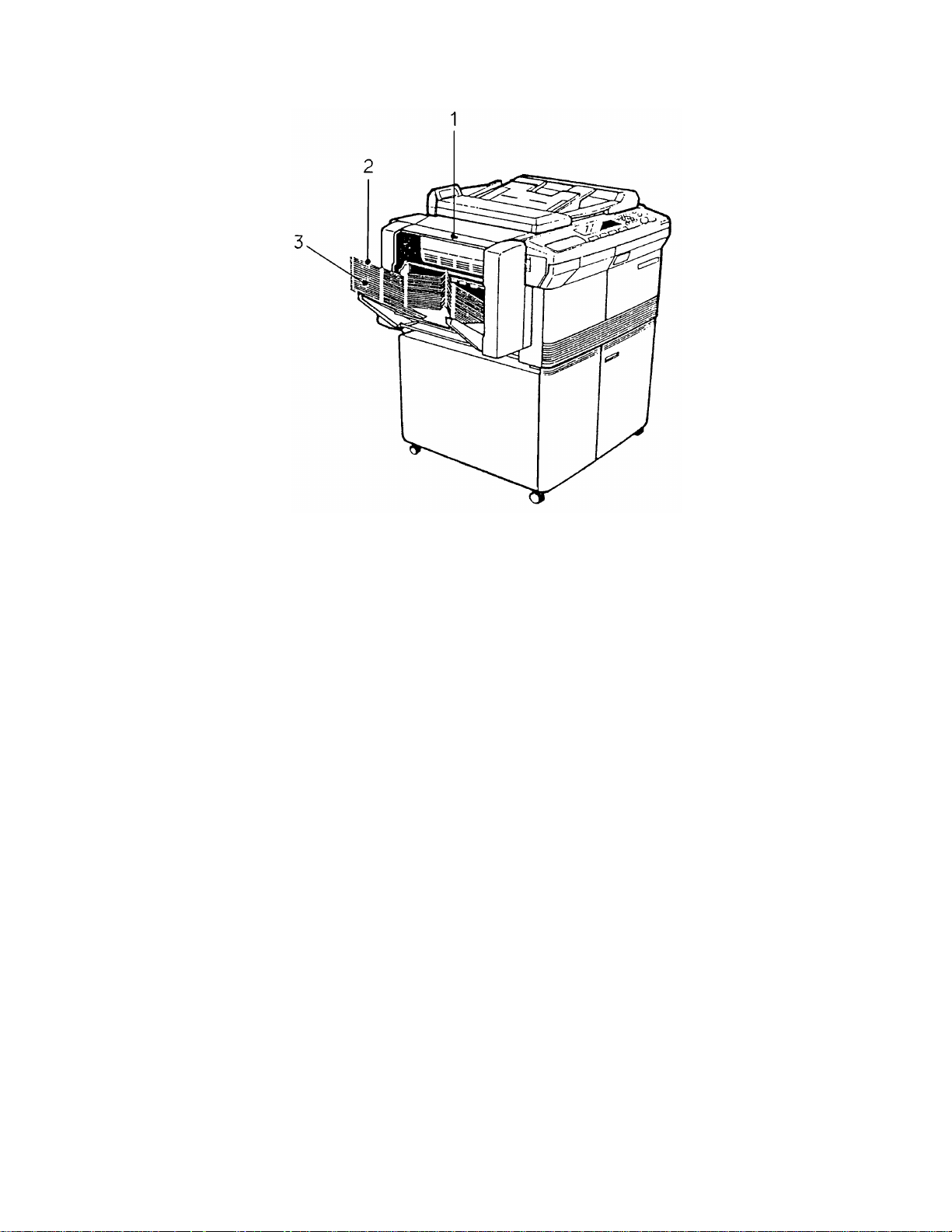
1. SORTER EXTERIOR
1. Top Button
Push it when clearing jammed paper from the sorter.
2. Top Bin Tray
The delivered copies are stacke d he re while sort or stack mode is not in use.
Also, when interrupt mod e is used while the sorter is operating, all copies are
delivered to the top bin tray.
3. Bin Trays
When the sorter is operating, copie s are de livere d to the bin tra ys accord ing to
the sort or stack modes.
- 2 -
Page 4
2. SORTER INSTALLATION
2.1 ACCESSORY CHECK
1. Sorter Adapter ............. .................... .........1
2. Mount Stay................................................1
3. Hinge Bracket: Front.................................1
4. Hinge Bracket: Rear.................................1
5. Mounting Stud Screw................................2
6. Screw M4 x 25............. .............. .. .. .. .. .. .. ...2
7. Screw M4 x 6......................................... ...2
8. Cable Clamp 5N.......................................1
9. Tapping Screw M4 x 10............... .. .. .. .. .. .. .2
10. Tapping Screw M4 x 6........................... ...5
2.2 INSTALLATION PROCEDURE
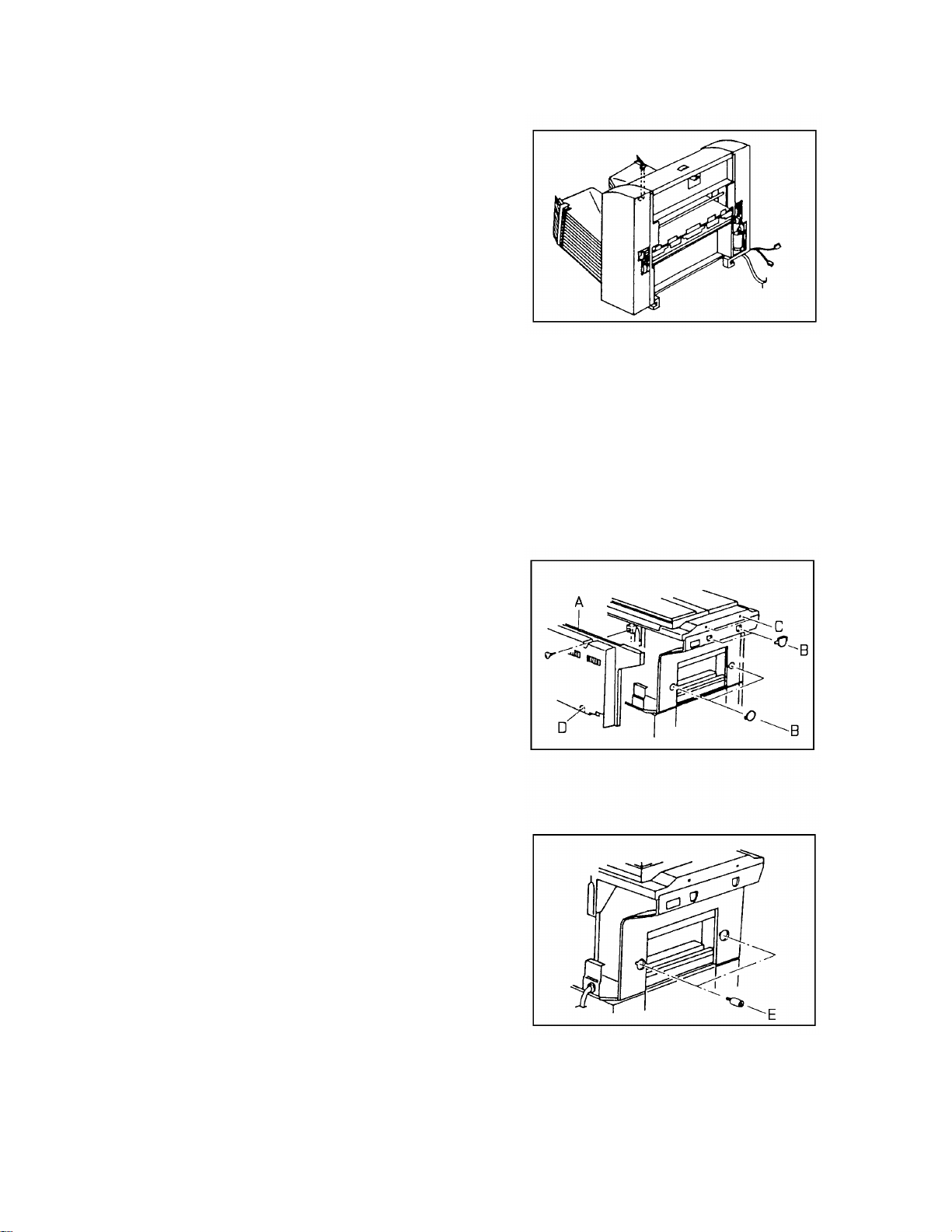
1. Turn off the main switch an d unplu g the
power supply cord of the copier.
2. Remove the rear cover [A] of the copier (4
screws).
3. Remove the four plastic caps [B] from the
left cover.
4. Remove the two screws [C] from the top
cover.
5. Cut off the cap [D] on the rear cover with
cutting pliers.
6. Screw in the two mounting stud screws [E].
7. Screw two M4 x 6 screws halfway into the
mounting studs.
- 3 -
Page 5
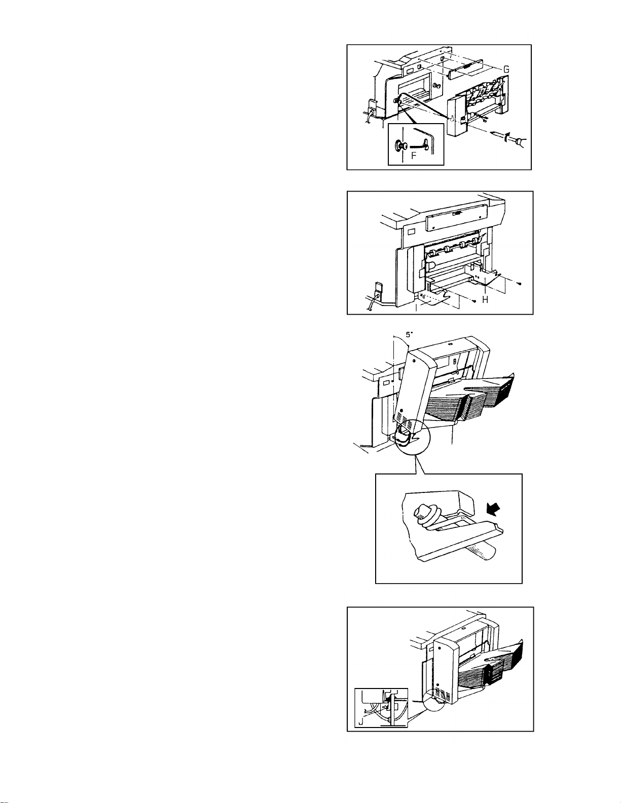
8. Hook the sorter adapter [F] on the screws,
and tighten the screws to fix the adapter.
9. Install th e mount stay on the copier with
two screws (M4 x 25) [G].
10. Install the front and rear hinge brackets [H,
I] on the copier with four screws (M4 x 6 Tapping).
11. Attach the sorte r to the hinge brackets by
positioning the lower sup port shaft in the
fork shaped groove of th e hinge bracket.
Tilt the sorter at an angle of 5 degrees
while setting it in the bra cket.
NOTE: Make sure that the ho ok of t he
tension spring is properly
positioned on the bra cket .
12. Install two tapping screws (M4 x 10 Tapping) [J] on the front and rear lower
bracket of the sorter.
13. Feed the connectors (2P, 3P) of the sorter
into the square holes in th e rea r h ing e
bracket from the rear side. Con ne ct two
connectors from the sorte r ada pter with
these connectors.
- 4 -
Page 6

14. Connect the sorter dc harness as follows:
• 11P to CN103 on the main board.
• 4P to 4P white connector from the
copier dc harness.
15. Secure the sorter grounding wire to the
power cord bracket [K] , usin g the original
screw.
16. Fix the sorter harness to the copier base
plate with the cable clamp [L] (M4 x 6 Tapping screw).
17. Replace the rear cover.
18. Check the operatio n of the hinge brackets.
19. Plug in the copier and turn on the main
switch.
C C
20. Access SP mode. ( + → )
C
LK
21. Enter SP No. 28 and change the setting
from "10" to "11".
(# → 28 → # → 0 → 0 → #)
22. Leave SP mode ( ).
C
23. Check the operatio n of the sorter.
- 5 -
Page 7

3. SPECIFICATIONS
Number of Bins: 20 bins
Type: Attachment type
Paper Size: Maximum A3, 11" x 17"
Minimum B6, 51/2" x 81/2"
Paper Weight: 60 to 90 g/m
Bin Capacity: Sort 35 sheets/A4, 20 sheets/B4 , 15 sheets/A3
Stack 30 sheets/A4 , 15 shee ts/B4, 10 sheets/A3
Top Bin Capacity: 100 sheets (all sizes)
Power Source: +5 volts and +24 volts from the copier.
Dimensions: 465 (W) x 304 (D) x 338 (H)
Weight: 9.5 kg
2
- 6 -
Page 8

4. ELECTRICAL COMPONENT LAYOUT
1
2
8
3
4
5
6
7
1. Sorter Control Board 5. Paper Sensor (Sorter Adapter)
2. Upper Limit Switch 6. 1/3 Revolution Switch
3. Sorter Cover Switch (Reed Switch) 7. Bin Home Position Switch
4. Feed Motor (Sorter Adapter) 8. Bin Drive Motor
- 7 -
Page 9

5. BASIC OPERATION
5.1 OPERATION SUMMARY
– Clear Mode –
When the main switch of the copier is turned on, all the bins are lowere d to the home
position. When th e St art key is pressed, the top bin shift s to the receiving positoin.
This mode is called Clear Mode. In this mode, all copies are stacked on th e to p bin.
The sorter also assumes the clear mod e whe n eit he r the inte rrupt mode or the
manual feed mode is selecte d.
Sorter operation be gin s wh en a sheet of copy paper actuates th e fu sing exit sensor.
At this time, the feed motor of the sorte r adapt er en erg izes. When the paper exits
onto the sorter bin, the pa pe r senso r is de-act ivated and the feed motor is then
de-energized. The copier main board monitors the paper sensor through the sorte r
control board to check for paper misf eeds.
– Sort Mode –
Pressing the sorter key once shif ts th e cop ier to the sort mode. In this mode, all
copies of the first original are delive red to separate bins starting from t he top . The
copies of the second original are delivered to the same bins, but starting from the
bottom. The copies of the third orig inal start from the top and so on.
The bin drive motor turns on to advance th e bins one step , 205 milliseco nd s aft er th e
copy has gone through the pap er sensor. If the Clear/Sto p or Sorter key is pressed
during the sort mode, all bins shift to the home position.
– Stack Mode –
Pressing the Sorter key twice shif ts the copier to the stack mode.
In this mode, all copies of the first original are delivere d to the top bin, all copie s of
the second original are delivere d to the secon d bin , an d so on. The bin drive mo tor
turns on to advance the bin one step, 205 millisecon ds af te r the last copy of the
original has gone through the pap er sen sor. If the sorter key is pressed during stack
mode, all bins shift to the home position.
- 8 -
Page 10

5.2 BIN DRIVE MECHANISM
Bin
Bin Drive Motor
Bin Guide
Transfer Wheel
Pin
[Y]
[Y]
[Y]
[Z]
[Z]
[Z]
[X]
[X]
[X]
Drive Shaft
Drive Gear
The bin drive mechanism moves th e bin s up an d do wn to receive copies under the
direction of the copier CPU. The main compo ne nt s of this me cha nism are the bin
drive gear, the transfer wheel, and the bins themselve s.
Pins on either side of each bin are inserte d int o the front and rear slots called bin
guides. The bins slide up and down along the bin guides. The bin guide has a special
shape at the middle as shown in the figu re: X, Y, and Z. The position "Y" is the
receiving position for copies. Whe n movin g up the bins, the posit ion "X" is the bin
inlet and "Z" is the bin outlet. On the other hand when movin g do wn the bins, the
function of "X" and "Y" is opposite.
When the bin drive motor is energized , th e drive gear is driven via idle gears. Then
the front and rear drive gears on the same sha ft turn the front and rear transfe r
wheels together.
The transfer wheels have three slots in them 120 degre es ap art . The transfer wheels
turn 120 degrees each time. As the tran sfe r wh eels t urn , th ese slo ts cat ch th e pin s of
the bin at the bin inlet and move the bin to the receiving position "Y". When the
transfer wheels turn again, the bin at the receivin g positio n is carried to the bin outlet
and the next bin is carried from the bin in let to th e rece iving posit ion.
- 9 -
Page 11

1/3 Revolution Switch
Actuator Cam
Front Transfer Wheel
The CPU monitors the position of the bins thro ugh pulses gene rat ed by the micro
switch (1/3 revolution switch) an d th e actuator cam on the front tran sfe r whee l. The
actuator cam has three grooves 120 degrees apart. As the front transfer whe el tu rns,
the ridge on the actuator cam activates the 1/3 revolution switch. When the bin s a re
properly positioned, the groove in the actuato r cam dea ctiva te s the switch an d the
bin drive motor stops turning.
When the copier main switch is turned on, all th e bin s are lowered until the bin home
position switch is activated. Then the top bin is moved up to the receivin g positio n
when the Start key is pressed, or Sort/Stack mode is selected.
There is a upper limit switch at the top of the rear bin gu ide for saf et y. If the 1/3
revolution switch fails to stop the transfer wheels and the top bin reaches the upper
limit switch, the bin drive motor is stopped.
- 10 -
Page 12

5.3 BIN SUPPORT MECHANI SM
Safety Lever
Middle
Gear
Bin Support
Pinion Gear
Bin Support
Rack
Transfer
Wheel
[Z]
[Y]
[X]
[Z]
[Y]
Bin Support Shaft
[X]
When the transfer whee ls t urn , the bin support racks are also mo ved up and do wn
via the middle gears and the bin support pinion gears. The bin support racks are
engaged with the bin supp ort shaft that is at the bottom and all the bins are seated
on this bin support shaft . Therefore, when the transfer wheel moves a bin up or
down, the other bins are moved up or down together.
The top of the bin suppo rt rack is eng ag ed wit h th e safety lever which moves in the
rails mounted along the bin gu ide . The safety lever limits the distance between the
top bin and the bottom bin to pre ven t th e bin s f rom comin g of f th e bin guid es,
especially when a custome r takes out the copies from the bin s. The safety lever
touches the pin of the top bin whenever there are bins above the transfer wheels.
However, when the to p bin is placed at the receiving posit ion "Y", the safety lever
slides around the transfer whe el an d blocks t he bin ou tle t slot "Z" as sho wn (top right
of the above drawing).
- 11 -
Page 13

5.4 TRANSFER WHEEL MECHANISM
The transfer wheel has thre e pairs of blo cks (6 blocks in tota l). Ea ch pair o f blo cks
makes one slot and deals with one bin at a time. The blocks are moved in and out by
the ridges around the transfer wheel shaft.
B1 = OUT
B2 = IN
B1 = OUT
B2 = OUT
Ridge
B1 = IN
B2 = OUT
[Figure 1]
B1 = OUT
B2 = IN
B1 = IN
B2 = OUT
Bin Guide
B1
B1
[Y]
[Z]
[X]
B2
B1 Pin
Ridge A
[Figure 2]
Figure 1 shows the ridges and the bin guide. The area aro un d th e transfer wheel is
divided into 5 sections (A, B, C, D, and E). A pair of blocks consists of Block 1 (B1)
and Block 2 (B2) as shown in figu re 2. Because ridges are placed at dif ferents
diameter around the transfer wheel shaft, the blocks B1 and B2 move in and out as
the transfer wheel rotates them through the five sections, as follows:
Section A: B1 = IN B2 = OUT
Section B: B1 = OUT B2 = OUT
Section C: B1 = OUT B2 = IN
Section D: B1 = OUT B2 = IN
Section E: B1 = IN B2 = OUT
B1
B2
B1
B1
B2
[Figure 3]
- 12 -
B2
Ridge D
Ridge C
[Figure 4]
Page 14

B1
B2
B2
Ridge D
[Figure 5]
B2
B1
B2
B1
Ridge E
[Figure 6]
B1
B1
Figures 2 to 6 show the relat ion ship between the ridges, the blocks B1 and B2, the
bin guide, and the bin’s pin, corresponding to the rotation of the transfer wheel
through the 5 sections. When moving the bins up, B1 is in and B2 is out while the
transfer wheel is catching the bin’s pin at the bin inlet [X] (sect ions E and A). When
the bin is placed at the receivin g po sition [Y], both B1 and B2 are out (se ctio n B).
While the bin is being carried to the bin outlet [Z], B1 is out and B2 is in (section C
and D).
B2
The blocks are carefully shaped so that minimu m f orce is required to pass the bin’s
pin through the bin outlet to the bin guide slo t above the transfer wheel. This is the
reason why a dc motor can be used in this model instead of a powerful ac motor to
move all the bins.
- 13 -
Page 15

6. REPLACEMENT
Top Cover
6.1 BIN REPLACEMENT
Rear Cover
Front Cover
1. Remove the sorter from the copier.
2. Remove the front cover (1 screw) and the rear cover (2 screws).
3. Lift off the top cover.
Safety
Lever
Rear Bracket
Transfer
Bin Drive
Motor Ass’y
Wheel
Support Shaft
Stopper Collar
Bin Support Rack
Drive Gear
Pin
Middle Gear
Bin Support Pinio n Gear
[Rear Side]
- 14 -
Page 16

Stopper
Collar
Support
Shaft
Safety
Lever
Front Bracket
Transfer Wheel
Bin Support Rack
[Front Side]
Middle Gear
Bin Support
Pinion Gear
Drive Gear
4. Remove the bin drive motor assembly (3 screws).
5. Remove the rear bracket (4 screws).
6. Remove the front bracket (5 screws).
7. Remove the front and rear bin support pin ion gea rs.
8. Remove the front and rear safety levers (1 screw each ).
9. Move the front and rear bin support racks off the gears.
10. Remove the front and rear middle gears.
11. Remove the front and rea r drive gears (1 E-ring each).
NOTE: Be careful not to lose the pins.
12. Remove the front and rear transfer wheels.
Bin
13. Remove the 2 support shafts (2 screws ea ch).
14. Remove the 2 stopper collars (1 screw each).
15. Lift up the bins along the bin guid e slot s and take them out from the sorter one by
one.
16. Apply Grease G501 on th e pin s of the new bins and reassemble th e sort er.
NOTE: • Only the top bin has mylars at the bin entrance .
• When installing the drive gears on the shaf t, make sure that the
dot-marked tooth of th e drive gea r eng ag es with the dot -marked teeth
of the transfer wheel as shown.
• When tightenin g th e bin support rack to the safet y le ver, keep a small
gap between the rack and the lever for smooth movement.
- 15 -
 Loading...