

Page 1

AUTOMATIC DOCUMENT FEEDER
(ADF)
– DF42 –
Page 2

CONTENTS
1. ADF EXTERIOR ................................................... 2
2. INSTALLATION PROCEDURE............................ 3
3. SPECIFICATIONS................................................ 6
4. MECHANICAL COMPONENT LAYOUT.............. 7
5. ELECTRICAL COMPONENT LAYOUT ............... 8
6. FUNCTIONAL OPERATION ................................ 9
7. REPLACEMENT...................................................13
- 1 -
Page 3
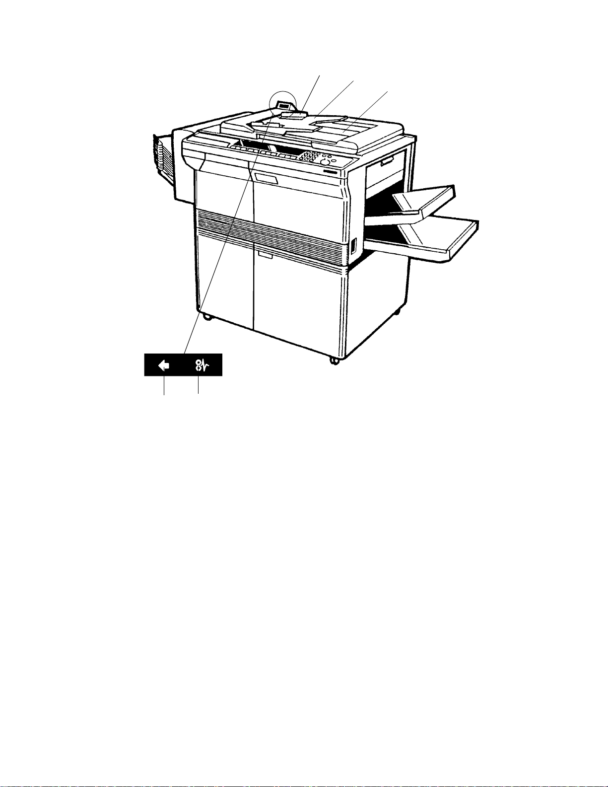
1. ADF EXTERIOR
1
2
3
45
1. Original Table
Place the originals to be fe d int o the ADF here.
2. Original Guides
Adjust these guides to cent er th e orig ina ls so tha t they are correctly fed onto the
exposure glass.
3. Original Stacker
Originals are stacked here af te r t hey exit from the ADF.
4. Insert Original Indicator
The green light is on while it is possible to place origin als in the ADF. After an
original is set, the light goes out.
5. Original Jam Indicato r
This indicator lights when an original jam occurs.
- 2 -
Page 4

2. INSTALLATION PROCEDURE
2.1 ACCESSORY CHECK
1. ADF Control Board.................................................................1 piece
2. Philips Screw with Flat Washer - M4 x 12......................... .. .. .2 pieces
3. Electric Screw - M4 x 8...........................................................1 piece
4. Plastic Cap..............................................................................1 piece
5. Stud Screw for Magnet Catch.............. .. .................................2 pieces
6. Philips Pan Head Screw - M4 x 8 (round head).....................2 pieces
7. Hinge Stud Screw...................................................................2 pieces
- 3 -
Page 5
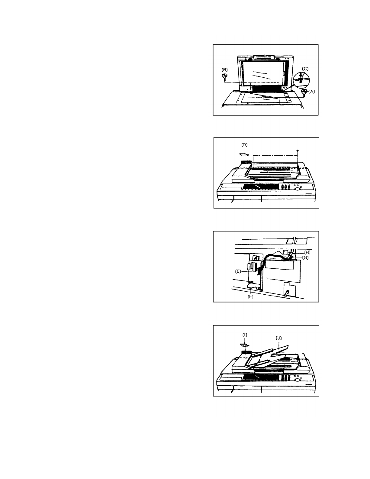
2.2 INSTALLATION PROCEDURE
• Make sure that main switch is turned off.
1. Remove the platen cover, 2 stud screws for
the platen cover, and 2 screws fixing the top
cover at the rear side.
2. Remove 2 front screws fixing th e top cover
and secure 2 stud screws for the magnet
catch [A]. (Fig. 1)
3. Secure 2 hinge stud screws [ B] half way a nd
mount the ADF so that the holes in the ADF
hinge bracket are aligne d with the studs, then
slide the ADF to the right. (Fig. 1)
4. Secure the ADF hinge bracket to the copier
optics frame with 2 screws (M4 x 12) [C].
(Fig. 1)
5. Lower the ADF and tighten the hinge stud
screws [B].
Fig. 1
6. Remove the copier rear cover and the plastic
cap with no hole [D] (left rear side ). (Fig. 2)
7. Install the ADF contro l boa rd on the main
board as shown. (Fig. 3)
8. Run the ADF harness [E] thro ug h the rear left
hole in the top cover and con nect it to CN2
on the ADF control board.
9. Connect the power supply connector (4P
white) [F] to CN3 on the ADF con trol board.
10. Secure earth wire [G] with a electric screw
(M4 x 8). (Fig. 3)
11. Install the twist band [H] and place the
interface harness on it, the n twist it tigh tly.
(Fig. 3)
12. After attaching the plastic cap with a hole [I ],
attach the copier rear cove r. (Fig. 4)
Fig. 2
Fig. 3
- 4 -
Fig. 4
Page 6

2.3 OPERATION CHECK
1. Turn on the main switch and confirm that th e insert original indicator ( ) lights.
2. Wait for the ready condition.
NOTE: It takes about 2 minute s.
3. Square a stack of originals and inse rt th e orig inals until the insert original
indicator goes out.
4. Press the Start key, th en the ADF shou ld sta rt op erating.
5. Check if the original jam indica tor lights when a paper jam is incurred by grabbing
the original which is supposed to be fed in .
6. After removing the jammed paper fro m t he ADF, the original jam indicator should
go off when the ADF returns to its original position.
7. Square the stack of originals, and reset the originals.
2.4 NON-RECOMMENDED TYPES OF ORIGINAL
CAUTION: The following types of originals are not recommended for use
with the ADF. Please place them directly on the exposure gla ss of
the copier.
1. Originals thicker than 105 g/m2 or thinner than 52 g/m2.
2. Paper with any kind of coatin g (such as carbon) on the back, or originals th at are
taped together.
3. Folded, curled, creased or damaged originals.
4. Bound, stapled, or clipped orig ina ls.
5. Mailing labels, perforated originals, or pasted originals,
6. OHP transparencies.
7. Thermal fax paper.
- 5 -
Page 7

3. SPECIFICATIONS
Original Size and Weight: B5 ~ A3 (weight: 52 ~ 105 g/m2)
Original Table Capacity: 30 sheets/A4, 15 sheets/A3 (70 g/ m2)
Copy Speed (1 to 1): 17 copies/minute for A4
Original Set: Face up, first sheet on top.
Original Separation: Separation Roller and Separat ion Belt
Original Set Position: Center Basis
Original Transportation: One Flat Belt
Original Detection: Photointerrupter
Power Source: DC 24 V, DC 5V (either 50 Hz or 60 Hz can be used)
from the copier
Dimensions: 626 (W) x 430 (D) x 56 (H) mm (without the Original Table)
Weight: 5 kg
- 6 -
Page 8

4. MECHANICAL COMPONENT LAYOUT
1
11
10
1312
14
89
7
6
5
2
3
4
1. Original Table
2. Feed-out Roller
3. (Feed-out Sensor)
4. Exit Transport Roller
5. Transport Belt
6. Belt Support Roller
7. (Pick-up Roller Position Sensor)
8. Transport Belt Drive Roller
9. Feed Roller
10. Registration Roller
11. (Registration Sensor )
12. Separation Belt
13. (Original Set Sensor)
14. Pick-up Roller
- 7 -
Page 9

5. ELECTRICAL COMPONENT LAYOUT
3
1
9
8
2
7
6
5
4
1. Indicator Panel 6. Pick-up Roller Position Sensor
2. ADF Motor 7. Original Set Sensor
3. ADF Position Sensor 8. Registration Sensor
4. Feed-out Sensor 9. Pulse Generator Sensor
5. Feed-in Clutch
- 8 -
Page 10

6. FUNCTIONAL OPERATION
Spring Plate
Pick-up Roller Position
Sensor
Transport Belt
6.1 SUMMARY
When an original is inserted face-u p into the ADF, the insert original ind icat or go es
off.
When the Start key is pressed, the pick-up roller starts turning and advances the
bottom original of the stack.
The feed roller and the friction belt are use d to feed-in and separate the originals.
Only the bottom original is fed because the friction belt preve nts any other originals
from feeding.
Registration rollers feed the original to the tran spo rt be lt until sligh tly af te r the origin al
trailing edge passes the regist rat ion sensor. Then the motor pauses and reverse s f or
a few pulses. This forces the original against the left scale and thus aligns the edge
of the original with th e scale .
When the scanner reaches the retu rn po sitio n at the end of scann ing the origin al,
the original is fed out from the ADF.
6.2 ORIGINAL PICK-UP • SEPARATION • FEED-IN MECHANISM
6.2.1 Original Pick -up
When an original is inserted, the insert origin al ind icator goes off. When the Start key
is pressed, the ADF motor and the feed-in clutch are energize d. Then the feed roller
starts turning.
The feed roller and the pick-up roller (a D-shaped roller) are linked by a timing belt .
Therefore the pick-up roller starts turning and advances the botto m original while the
clutch is on.
A spring plate is installed above th e pick-u p roller. This plate pushes down the
original stack against the pick-up roller to help the roller feed the bottom original.
Original Set Sensor
Friction Belt
Registration
Sensor
Friction Pad
Registration
Roller
Feed Roller
Left Scale
- 9 -
Pick-up Roller
Page 11

6.2.2 Original Separ ation
Friction Pad
Spring Plate
Pick-up Roller Position
Sensor
Transport Belt
The feed roller and the friction belt sepa rat er th e orig ina ls. The friction pad prevents
the uppermost original from be ing fed in .
Friction Belt
Registration
Sensor
Registration
Roller
Feed Roller
Original Set Sensor
Left Scale
Pick-up Roller
µ1: Friction coefficient betwe en feed rolle r and origin al
µ2: Friction coefficient between friction belt and original
µ3: Friction coefficient be twe en origin al she et s.
µ1 > µ2 > µ3
6.2.3 Original Feed-in Mechanism
The bottom original separated by the frictio n belt is fed to the reg istra tio n rolle rs. The
registration rollers fe ed the origin al to the tran spo rt be lt, the n th e orig ina l p asse s the
registration sensor.
The ADF determines original size throu gh the use of the registration sensor.
The original’s length is calculated by countin g the numbe r of pulses while the
registration sensor is on.
Original size detection is necessary for the ADF’s feed-in/feed-out timing.
- 10 -
Page 12

6.3 ORIGINAL TRANSPORTATION MECHANISM
The transport belt is directly driven by the mot or’s worm-g ear.
The registration rollers feed the origina l to the tra nsp ort belt until slight ly aft er th e
original trailing edge passes the registration sensor. Then the motor pauses and
reverses for a few pulses. This forces the original against the left sca le an d th us
aligns the edge of the original with the scale to prevent original skew.
6.4 ORIGINAL FEED-OUT MECHANISM
The feed-out roller is connecte d to the tran spo rt be lt by th e feed -ou t rolle r d rive belt
(an O-ring belt). At the end of scanning, the ADF motor starts tu rnin g again after a
feed-out signal from the copier. Then the feed-o ut roller fe eds out the original from
the ADF.
6.5 NEXT ORIGINAL FEED
When the trailing edge of th e original passes the feed-out sensor, the feed-in clut ch
turns on to feed the next original. The feed-in clutch on timing depends on the
original size.
6.6 COMPLETION OF ORIGINAL FEED
There is a disk with a notch on the pick-up roller shaft . The flat surface of the pick-up
roller is positioned upward whe n the pick-u p rolle r positioning sensor detects the
notch.
When the feed-in clutch turns on, the pick-up roller rotates together with the feed
roller. During a copy job for a set of originals, the copier disregards the output of the
pick-up roller positioning sen sor. However, when the last original is fed out from th e
ADF, the ADF motor keeps turning and the feed-in clutch tu rns on until t he pick-up
roller positioning sensor dete cts th e notch in the pick-up roller sha ft. This is to
position the flat surface of the pick-up roller up ward for easy in sert ing of th e next set
of originals.
- 11 -
Page 13

6.7 ADF CONTROL BOARD
1. LED
LED1 - When the ADF is lifted, LED1 lights.
LED2 - When the registration sensor is
activated, LED2 lights.
CN1
CPU
DPS2
LED3 - When the feed-out sensor is activated,
LED3 lights.
LED3
LED2
LED1
2. DPS1
12
CN3
FUSE(125V,1.25A)
ON Motor Test ADF free run
OFF Normal Normal
• No 1 ON: Use to test the ADF drive without an original.
• No 2 ON: ADF free run while detecting originals.
* Start key is SW1.
NOTE: The DIP switch settings must be cha nged when the ma in switch is off.
SW1
DPS1
CN2
3. DPS2
Adjust it when the ADF misde te cts the original length.
• If the detected length is less than the actual original length, turn DPS2 clockwise.
• If the detected length is large r tha n the act ua l origin al length, turn
counterclockwise.
Ref.) The relation of each paper length is as follows:
A3 > B4 > A4 lengthwise > B5 lengthwise > A4 side ways > B5 side ways
NOTE: Turn the main switch off and on after the adjustment.
- 12 -
Page 14

7. REPLACEMENT
Separation Bel t
Assembly
7.1 SEPARATION BELT REPLACEMENT
Tension Springs
Tension Bar
Belt Guide
Separation Belt
1. Remove the feed-in cover (3 screws).
2. Remove the separation belt assembly (2 screws).
3. Remove the 2 tension springs and the tension bar.
4. Remove the separation belt from the belt guide.
- 13 -
Page 15

7.2 TRANSPORT BELT REPLACEMENT
Belt Support Roller
Plastic Bushing
Original Table
Feed-out Cover
Transport Belt
Drive Roller
Feed-in Cover
Handle Cover
Bearing
Transport Belt
Front Transport Bracket
Holder Hook
Bearing
Transport Gear
1. Remove the original table from th e ADF by slidin g it to the right.
2. Turn off the main switch and remove the ADF fro m the copie r.
3. Place the ADF on a table wit h th e transport belt side up.
4. Remove the feed-in cover (3 screws), the handle cover (4 screws), and the
feed-out cover (2 screws).
5. Remove the transpo rt ge ar an d th e be arin g from the front side (1 E-ring).
6. Slide the other bearing on the transport belt drive roller shaft to the rear (1 E-ring ).
7. Free the transport belt drive roller from the ADF frame.
8. Remove the front transp ort bracke t from the ADF main cover (2 screws).
9. For all the belt support rollers, press down the belt support roller shaft to slide out
10. Take out the transport belt from the rollers.
11. Install a new transport be lt and reassemble the ADF.
the front end from the holder hook.
NOTE: Make sure that all the plastic bushin gs for the belt support roller shaft
are properly positioned in the hold er hooks (8 bu shin gs for the front and
rear).
- 14 -
Page 16

7.3 FEED ROLLER REPLACEMENT
Bearing
Bushing
Registration Idl e Roller
Bearing
Transport
Gear
Tie-wrap
Bushing
Feed-in Clutch
Transport Belt
Drive Roller
ADF Main Cover
Front Side Plate
1. Remove the original table from th e ADF by slidin g it to the right.
2. Turn off the main switch and remove the ADF fro m the copie r.
3. Place the ADF on a table wit h th e transport belt side up.
Feed Roller
Registration
Idle Roller
4. Remove the feed-in cover (3 screws) and th e hand le cove r (4 screws).
5. Remove the transpo rt ge ar an d th e be arin g from the front side (1 E-ring).
6. Slide the other bearing on the transport belt drive roller shaft to the rear (1 E-ring ).
7. Free the transport belt drive roller from the ADF frame.
8. Remove 2 screws securing the front side plate to the ADF main cover.
9. Remove the tie-wrap from the feed-in clutch.
10. Remove the feed-in clutch and the bushing from the feed roller shaft (1 E-ring).
11. Remove the bushing from the rear end of the feed roller sha ft (1 E-ring).
12. Slide the registration idle roller (2nd from the rear) to the rear of the shaft as
shown.
13. Free the rear end of the feed roller shaft free from the rear side pla te by shift ing it
to the front.
14. Remove the 3 registration idle rollers (at the rear side) from the feed rolle r sh af t.
15. Remove the feed roller from the shaft (1 E-ring).
16. Install a new feed roller on the sha ft and reassemble the ADF.
NOTE: • Make sure that the feed roller rotates counterclockwise (as seen fro m
the front) free ly o n th e shaft.
• When installing the feed-in clutch, make sure that the fork of the clutch
is properly engaged with the stopper.
- 15 -
Page 17

7.4 PICK-UP ROLLER REPLACEMENT
Plastic
Bushing
Pick-up
Roller
Pick-up Roller Assembly
ADF Main Cover
1. Perform steps 1 to 7 of the feed roller replacement.
2. Remove the pick-up roller assembly from the ADF main cove r (2 scre ws).
3. Remove the plastic bushing from th e pick-up roller shaft (1 E-ring).
4. Slide out the pick-up roller.
5. Install a new pick-up roller and reassemble the ADF.
NOTE: Be careful not to damage th e screw holes for the pick-up roller assembly
as they do not have metal inserts on the main cove r.
- 16 -
 Loading...