

Page 1
SERVICE MANUAL
FT5034C
Page 2

CONTENTS
1. INSTALLATION.................................................... 2
2. OVERVIEW........................................................... 7
3. COPY PROCESS ................................................. 11
4. SECTION DESCRIPTIONS .................................. 13
5. SP MODE/DIP SW TABLE................................... 92
6. CALL SERVICE CONDITIONS ............................ 98
7. PREVENTIVE MAINTENANCE............................105
8. TROUBLESHOOTING..........................................114
9. ELECTRICAL DATA
- 1 -
Page 3

1. INSTALLATION
1.1 INSTALLATION REQUIREMENTS....................3
1.2 INSTALLATION PROCEDURE..........................4
- 2 -
Page 4
1.1 INSTALLATION REQUIRE MENTS
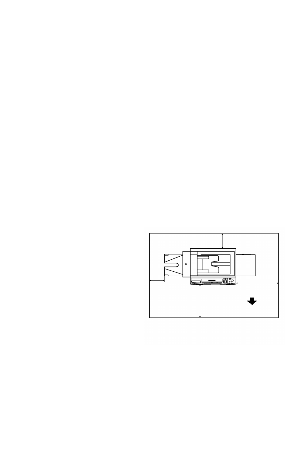
more than 10 cm
The installation loca tion should be carefully chose n be cau se en vironmental
conditions greatly aff ect the perf ormance of a copier.
1. Environments to Avoid
• Avoid any area exposed to direct sunlight or strong light (Illumination must be
less than 1500 Lux).
• Avoid any area expose d to extre mes of temperature and humidity (standard
condition: 10°C ~ 30°C, 15% ~ 90%).
• Avoid any area expose d to hea te d air fro m a hea te r.
• Avoid any area where tempe rature suddenly changes from low to high or vice
versa.
• Avoid placing the copier in an area filled with dust, and subjected to frequent
strong vibration.
• Avoid narrow space (10 m
2. Access to Copier
3
).
Place the copier near a power source, providing clearan ce as shown. The copier
must be level within 5 mm both front to rear a nd left to right.
3. Power Connection
• Input voltage level:
220 V/50 Hz, more than 10 A
• Avoid connecting the power cord
to a socket that already has
power cords attached
• Permissible voltage fluctuat ion:
220 V (±10%)
• Avoid using a power cord
more than
50 cm
more than
70 cm
more than 80 cm
Front
extension. If you must use one,
make sure that it can carry 250
V, 10 A and that it is less than 5
m long.
4. Earth Connection
• Be sure to ground the mach ine prop erly.
• Do not connect the grounding wire to a gas pipe.
- 3 -
Page 5

1.2 INSTALLATION PROCEDURE
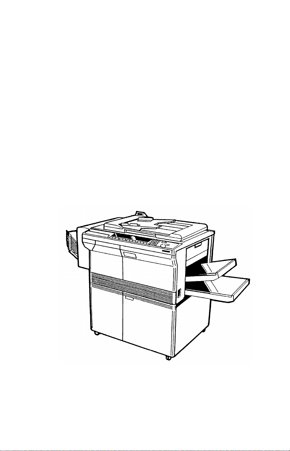
NOTE: 1. When lifting and movin g th e
copier, grasp the black painted
stays on each side as shown.
2. When the optional sorter is
installed, the above mentioned
stays can not be held. Wear
gloves to protect hands from the
edges of the copier base plate.
3. When transporting the cop ier,
remove all the developer and
toner inside the machine. Also
make sure to lock the scanner
with the lock plate.
1. Unpacking and Clamps Removal
1. Remove the shipping tapes from the copier
as follows:
1) From platen cover to front cover
2) Manual table
3) Feed guide (cassette insert sectio n)
Scanner Lock
Plate Cover
4) Transport guide plate
5) T/S corona unit
6) Toner shield glass
7) Front loading cassett e leve r
8) Operation panel cover
9) PTL, QL filter
10) Relay lower guide plate
2. Remove the seal from the toner tank
entrance.
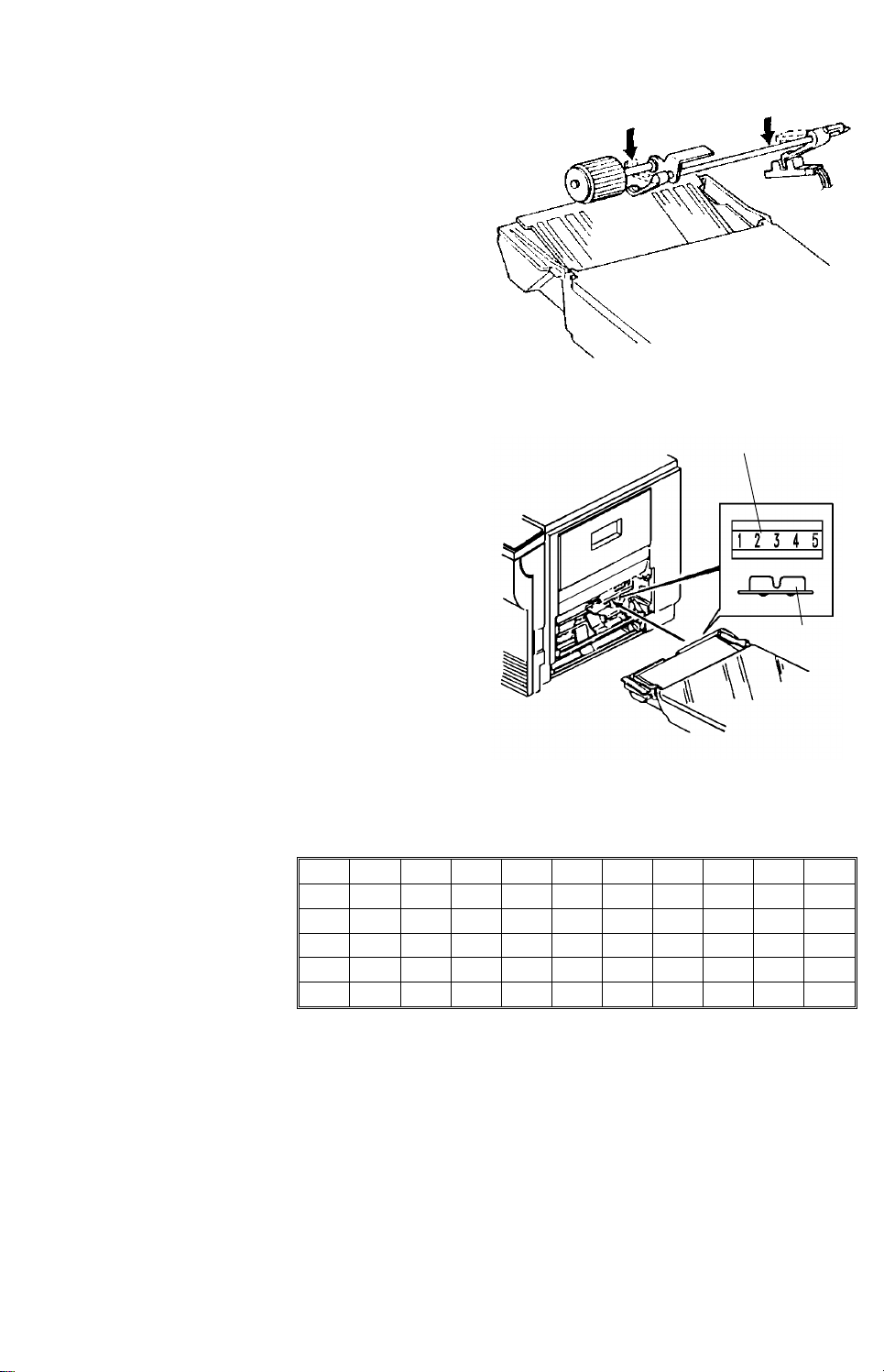
3. Remove the wedge (red) from between the
registration rollers.
4. Remove the scanner lock plate cover.
5. Remove the scanner lock plate (1 screw).
(Save the scanner lock plate for future use.)
6. Reinstall the scanner lo ck plate cover.
Scanner Lock
Plate
Development
Lock Leve r
7. Adjust the machine level by tu rning the
rubber foot on the base plate.
- 4 -
Page 6
2. Developer Supply
Charge Corona Unit
Place a clean sheet of pape r on yo ur work
surface.
1. Raise the development lock le ver and pu ll
out the development unit. Place the unit on
a clean shee t of paper.
2. Separate the toner tank from the
development unit (2 screws).
3. Pour one bag of developer (1 kg) into the
development unit while turn ing the knob
counterclockwise to distribute the developer
evenly.
4. Remount the toner tank on the development
unit.
NOTE: Make sure that there is no gap
between the toner tank and the
development unit.
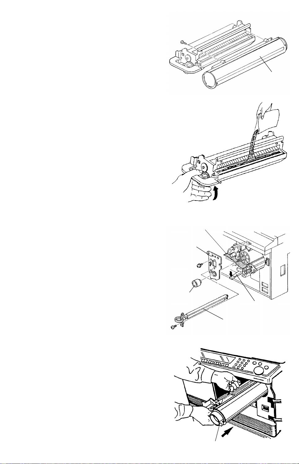
3. Drum Protective Sheet Removal
1. Lower the T/S corona unit lever.
Toner Tank
Drum Protective
Sheet
Drum Stay
2. Remove the charge corona unit together
with the wire cleaner (1 screw).
3. Remove the drum stay (1 knob and 1
screw). The drum knob is reverse threaded.
4. Pull out the drum prot ect ive sheet.
5. Reinstall the drum stay an d the charge
corona unit with the wire cleaner.
6. Raise the T/S corona unit lever.
4. Development Unit Installation
1. When installing the development unit, be
sure the development unit rail is pro perly
engaged with the unit guide rail on the
copier. (Make sure that the PTL and QL
filters are in their original position s.)
2. Shake the toner cartridge well and insert
the cartridge. (Refer to the ton er sup ply
guide decal on the front right cove r.)
Drum Knob
T/S Corona Unit
Lever
Toner Cartridge
- 5 -
Page 7

5. Perform the Drum Conditioning
(This operation must be performed after
developer and drum insta llation.)
1. Open the front right cover and move the
drum conditioning switch on the re verse
side of the operation pan el to the left. Close
the front right cover a nd switch the power
on. (The Start key changes from red to
green after 2 min.)
2. Lower the platen cover and enter "99"
using the number keys and press the Sta rt
key. (Drum conditioning takes about 5 min.)
3. After the drum conditioning is finished,
open the front right cover, move the drum
conditioning switch to the right an d close
the front right cover.
4. Place the paper size actuato r a nd size
decal on the cassette (A4 lengthwise or B5
lengthwise) and load paper into the
cassette.
Drum Conditioning
Switch
5. Check the machine operation and copy
quality.
- 6 -
Page 8

2. OVERVIEW
2.1 SPECIFICATIONS..............................................8
2.2 GUIDE TO COMPONENTS................................9
- 7 -
Page 9
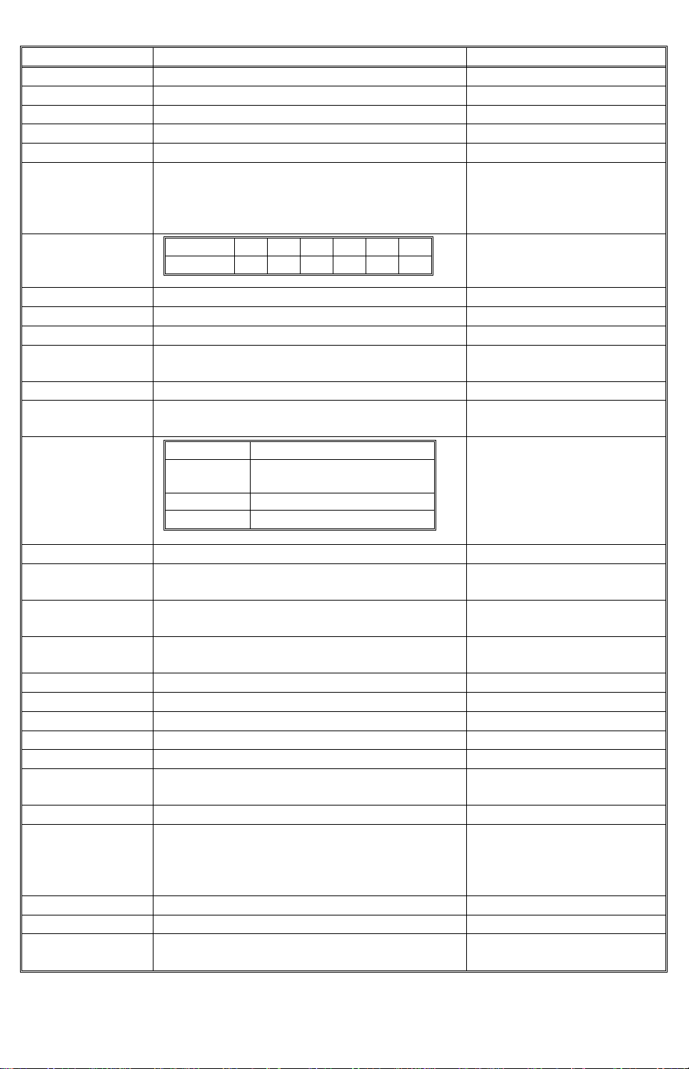
2.1 SPECIFICATIONS
Items Specifications Remarks
Configuration Desk top
Copy Process Dry electrostatic transfer system
Originals Sheet/book
Original Size Maximum A3
Copy Paper Size Maximum A3, Minimum A6 Lengthwise
Copy Paper Weight 52 g/m
Copy Speed
2
~ 157 g/m
Originals A3 B4 A4 B5 A4R B5R
Speed 20 23 34 37 26 30
Warm-up Time Less than 2 min.
First Copy Time 4.5 seconds/A4 sideways
Copy Number Input 1 to 99, Numeric key pad
Paper Feed Three Cassettes (including the front loading
cassette) + Bypass Feed Table
Charge System Dual wire corotron system
Exposure System Slit exposure
(exposure lamp: 180 V, 320 W)
Reproduction
Ratios
Full Size 1 : 1
Reduction 93%, 87%, 82%, 71%, 61%,
Enlargement 115%, 122%, 141%
Zoom 50%~200% in 1% steps
Photoconductor Selenium-drum (F type)
Development
Magnetic brush system
System
Image Density
Control
Toner
Development Bias system + Exposure Control
System
Cartridge exchange (300 g): oilless
Replenishment
Cleaning Type Cleaning blade and brush with PCC
Image Fusing Heat roll type (220 V, 800 W)
Image Transfer Corotron system
Paper Separation Dual wire ac corona and pick-off pawls
Quenching System Photo-quenching
Auto Clear All input modes are reset 60 seconds after the
copier is last used.
Power Source 220 V/50 Hz, 8 A
Power
Consumption
Maximum: Less than 1.5 kW
Average: Warm-up 0.8 kW
Weight 79 kg
Dimensions 765 (W) x 666 (D) x 426 (H) mm
Peripheral
Sorter and Auto Document Feeder
Equipment
2
50%
Stand by 0.18 kW
Copy cycle 1.0 kW
F/L cassette: 64 ~ 90 g/m
1st & 2nd cassette:
52 ~ 127 g/m
2
2
By-pass feed: 52 ~ 157 g/m
Cassette: 250 sheets x 3
Bypass Feed: 50 sheets
Reproduction Ratio Change:
Full size ↔ Reduction or
Enlargement:
Less than 3.5 seconds
Enlargement ↔ Reduction:
Less than 5.0 seconds
2
- 8 -
Page 10
2.2 GUIDE TO COMPONENTS
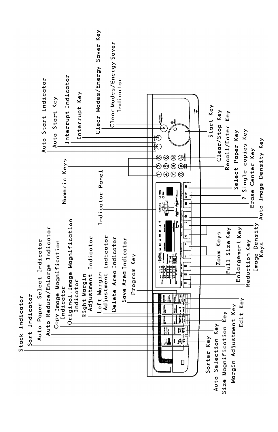
1. Operation Panel
- 9 -
Page 11
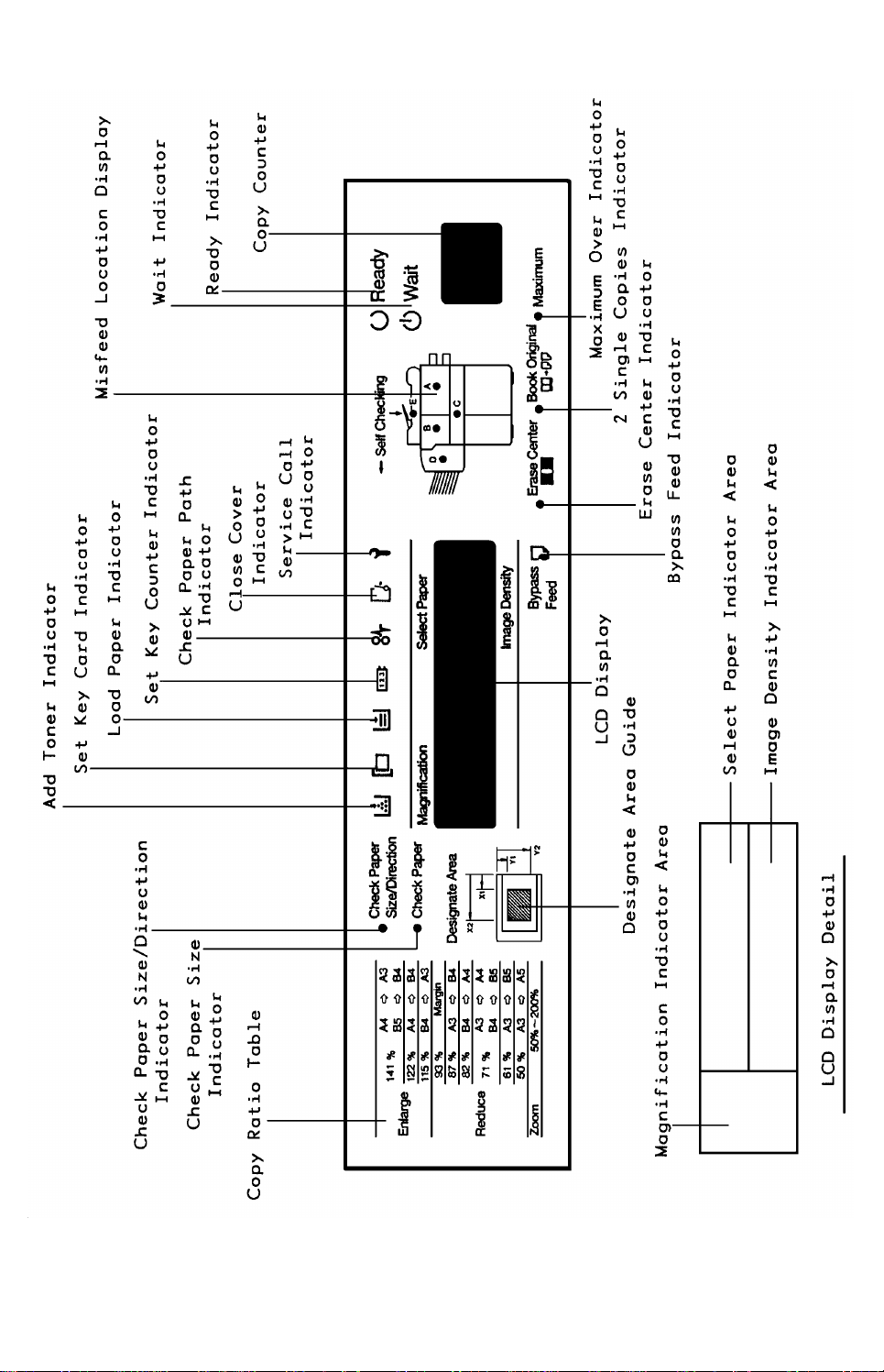
2. Indicator Panel
- 10 -
Page 12

3. COPY PROCESS
3.1 COPY PROCESS DIAGRAM .............................12
- 11 -
Page 13
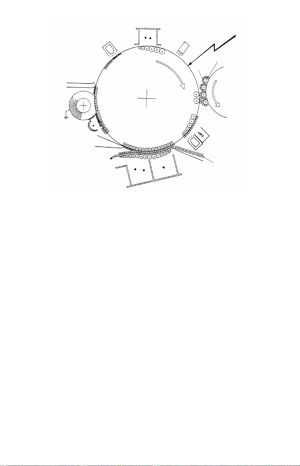
3.1 COPY PROCESS DIAGRAM
Toner
Quenching
Lamp
Charge Corona Unit
Erase Lamp
Exposure
Carrier
Cleaning Blade
Cleaning
Brush
Pre-Cleaning
Corona (PCC)
Pick-off Pawls
1. DRUM CHARGE
In the dark the charge corona unit gives a uniform
positive charge to the selenium drum. The charge
remains on the surface of the drum because th e
photoconductive selenium has high electrical resistance
in the dark.
2. ERASE
The erase lamp illumi na tes the areas of the ch arg ed
drum surface that wil l no t be use d fo r the cop y imag e.
The resistance of the drum in the illumi na ted areas
drops and the charge on those areas dissipates.
3. EXPOSURE
An image of the original is ref le ct ed ont o the selenium
drum surface via the optics assembly. The charge on
the drum surface is dissipated in direct proportion to the
intensity of the reflected light, thus producing an
electrica l la tent image on th e drum surface.
4. DEVELOPMENT
Negatively charged toner is attracted to the positively
charged areas of the drum, thus develop ing th e late nt
image. (The negativ e tri bo el ec tric charge is caused by
rubbing action between the carrier an d toner particles. )
5. ID SENSOR
The main CPU checks toner density by directly sensi ng
the image densit y at the beginning of the fi rst cop y cy cl e
after the main switch is turned on, and at every 10th
copy after that.
6. PRE-TRANSFER LAMP (PTL)
The PTL illuminates the dr um to remov e al l po si tive
charge from the exposed areas of the drum. This
prevents the toner particle s from being reatt rac ted to
the drum surface during paper separation and makes
paper separation easi er.
F TYPE
Photoconductor Drum
Separation
Corona Wire
Development
Roller
ID Sensor
Pre-Transfer Lamp
Paper
Transfer
Corona Wire
7. IMAGE TRANSFER
Paper is fed to the drum su rfa ce at th e proper time so
as to align the copy pap er an d the developed image on
the drum surface . Then, a strong positive charge is
applied to the reverse side of the copy paper, providing
the electrical force to pull the toner pa rti cl es from the
drum surface to the copy pap er. At the same ti me , th e
copy paper is electrically attracted to the drum surface.
8. PAPER SEPARATION
A strong ac corona discharge is applied to the reverse
side of the copy paper, gradually reducing the positive
charge on the copy paper and breaking the electrical
attraction between the paper and the drum. Then, the
stiffness of the copy paper causes it to separate from
the drum surface. The pick-off pawls help paper which
has low stiffness to separate from the drum.
9. PRE-CLEANING CORONA (PCC)
The PCC applies a positive charge to any toner
remaining on the drum after image transfer. This
causes repulsion between the toner particles and the
drum and thereby makes cleaning more effective.
10. CLEANING
The cleaning brus h removes part of the tone r o n th e
drum and loosens the remainder. The cleaning bl ad e
then scrape s of f the loosened t on er.
11. QUENCHING
The light fro m th e quenching la mp, which is a cold
cathode tube, electrically neutralizes the surface of the
selenium drum.
- 12 -
Page 14

4. SECTION DESCRIPTIONS
4.1 MECHANICAL COMPONENT LAYOUT............14
4.2 DRIVE LAYOUT
(INCLUDING PERIPHERALS) ...........................15
4.3 ELECTRICAL COMPONENT LAYOUT .............16
4.4 PAPER FEED AND REGISTRATION ................18
4.5 OPTICS...............................................................28
4.6 AROUND THE DRUM ........................................44
4.7 DEVELOPMENT AND TONER SUPPLY...........50
4.8 ID SENSOR AND PTL........................................62
4.9 IMAGE TRANSFER, PAPER SEPARATION
AND PAPER TRANSPORT................................71
4.10 CLEANING .......................................................75
4.11 FUSING.............................................................83
4.12 MISFEED CHECK ............................................89
4.13 PULSE GENERATOR ......................................90
4.14 OTHERS...........................................................91
- 13 -
Page 15
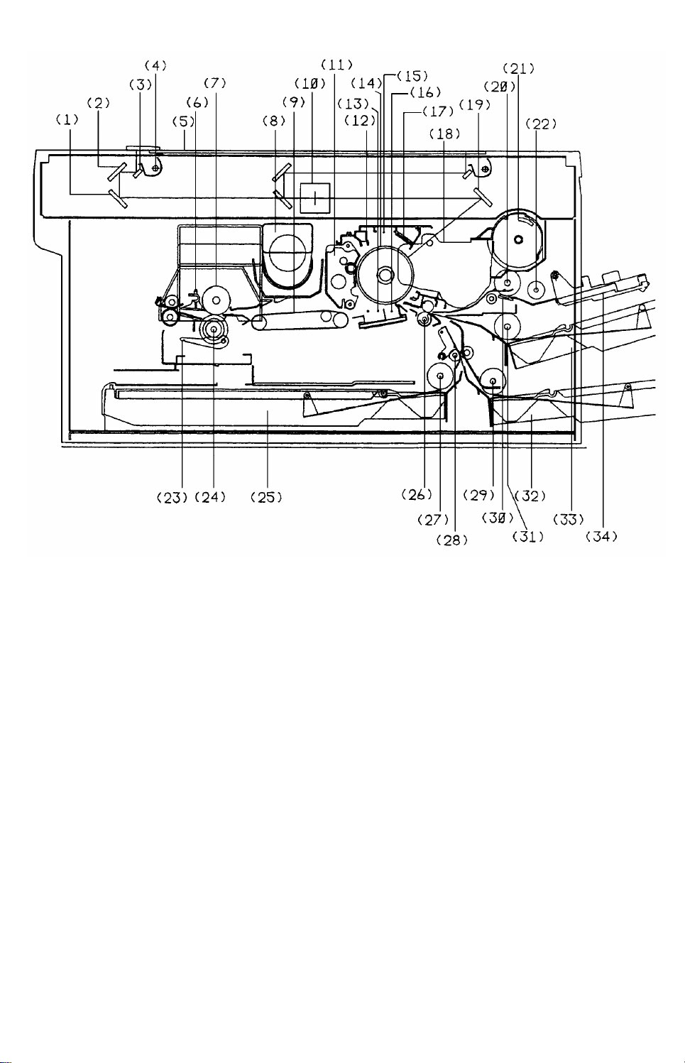
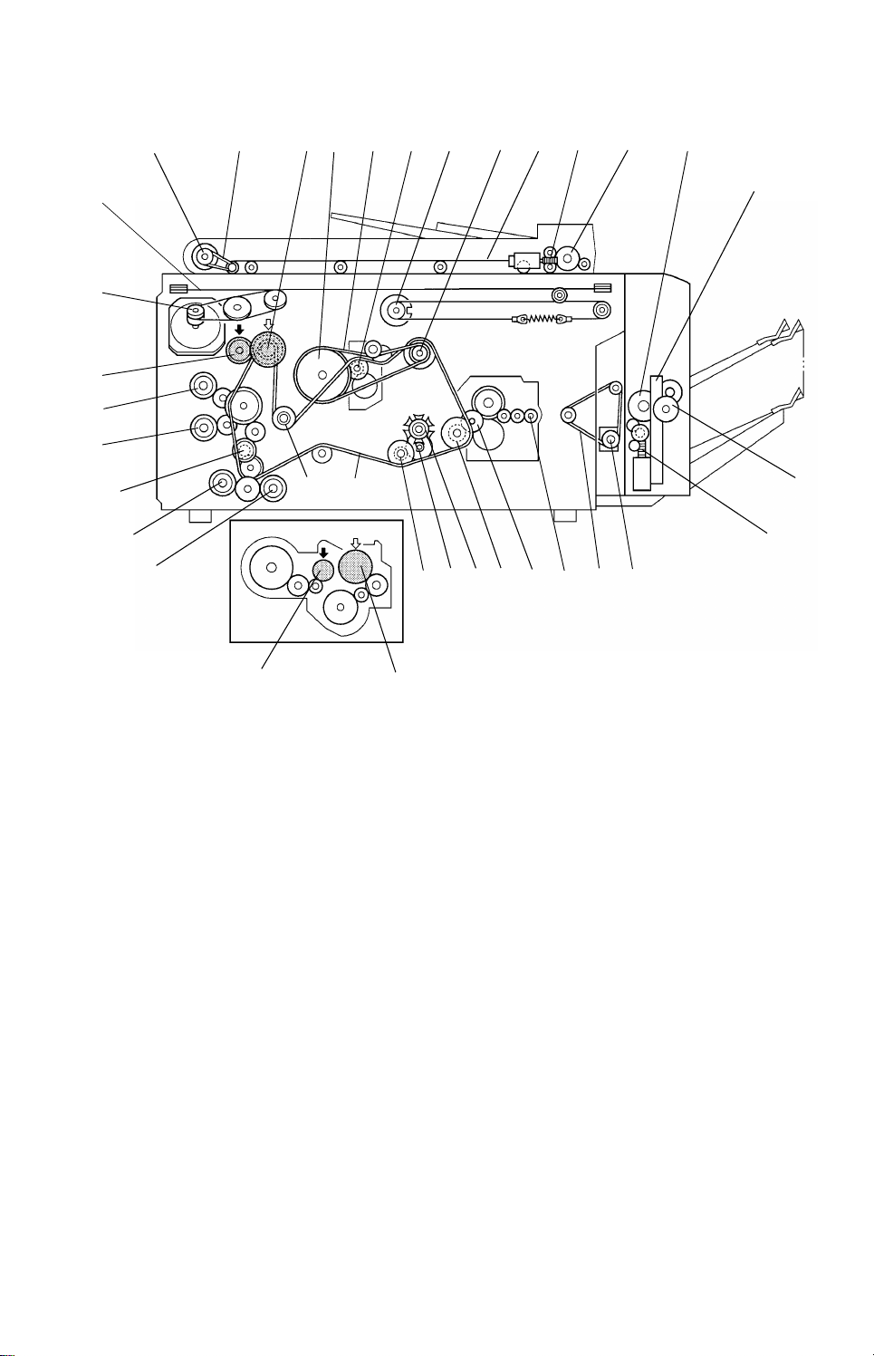
4.1 MECHANICAL COMPONENT LAYOUT
1. 3rd Mirror
2. 2nd Mirror
3. 1st Mirror
4. Exposure Lamp
5. Exposure Glass
6. Hot Roller Stripper
7. Hot Roller
8. Main Motor
9. Transport Belt
10. Lens
11. Cleaning Unit
12. Quenching Lamp
13. Separation Corona Wire
14. Drum
15. Charge Corona Wire
16. Transfer Corona Wire
17. Erase Lamp
18. Development Unit
19. 4th Mirror
20. Feed Roller (By-pass Feed)
21. Toner Tank
22. Pick-up Roller
23. Pressure Lever
24. Pressure Roller
25. Front Loading Ass’y
26. Registration Roller
27. Feed Roller (F/L)
28. Relay Roller
29. Feed Roller (2nd)
30. Friction Pad
31. Feed Roller (1st)
32. 2nd Casse tte
33. 1st Cassette
34. By-pass Feed Table
- 14 -
Page 16
4.2 DRIVE LAYOUT (INCLUDING PERIPHERALS)
33
32
31
30
29
28
1234567
2425
27
26
2223
89
21
20
19
10 11
17
18
12
13
14
15
16
35
1. DF Feed-out Roller
2. Feed-out Roller Drive Belt
3. Pulse Generator Sprocket/Toner
Supply Drive Gear
→ 34. Development Drive Gear
4. Drum Drive Pulley
5. Drum Drive Belt
6. Cleaning Drive Sprocket
7. 2nd Scanner Drive Pulley
8. Main Motor Sprocket
9. DF Transport Belt
10. DF Belt Drive Motor Gear
11. DF Feed Roller
12. Bin Transfer Wheel
13. Bin Support Rack
14. Bin Support Pinion Gear
15. Bin Drive Motor Gear
16. (Sorter Adapter) Feed Motor Pulley
34
17. Sorter Adapter Drive Belt
18. Fusing Exit Roller Gear
19. Fusing Drive Release Gear
20. Transport/Fusing Drive Sprocket
21. Cam Wheel
22. Cam Drive Gear
23. Cam Drive Sprocket
24. Main Drive Chain
25. Registration Clutch
26. F/L Feed Clutch
27. 2nd Cassette Feed Clutch
28. Relay Clutch
29. 1st Cassette Feed Clut ch
30. By-pass Feed Clutch
31. Toner Supply Clutch
→ 35. Toner Supply Drive Gear
32. Scanner Motor Pulley
33. Scanner Drive Wire
- 15 -
Page 17
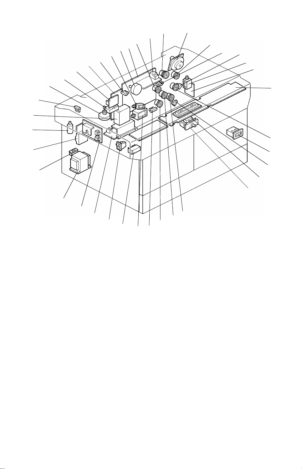
4.3 ELECTRICAL COMPONENT LAYOUT
1
13
24
36
35
34
33
32
31
30
29
28
27
26
25
23
22
21
20
19
18
17
37
16
15
38
14
2
3
4
5
6
7
8
9
10
11
12
1. Scanner Motor
2. By-pass Feed Clutch
3. Pulse Generator Sensor
4. 1st Cassette Paper End Sen sor
5. By-pass Pick-up Solenoid
6. Feed Control Board
7. Operation Panel Board
8. 1st Feed Clutch
9. Total Counter
10. 2nd Cassette Pap er End Sensor
11. Door Switch
12. Door Switch
13. 2nd Feed C lutch
14. Relay Roller Clutch
15. F/L (Front Loading) Feed Clutch
16. F/L Tray Paper End Sensor
17. Cleaning Solenoid
18. Main Power Relay
19. Main Switch
20. Power Supply Board
21. Lamp Regulator Board
22. Power Transformer
23. Main Fuse
24. Fusing Control Board
25. Noise Filter
26. Power Pack - T/S/PCC
27. Scanner Home Position Sensor
28. Lens Motor
29. Main Motor Capacitor
30. Lamp Stabilizer
31. ADF Control Board
32. 2nd Scanner Home Position Sensor
33. Pick-off Solenoid
34. 2nd Scanner Motor
35. Main Board
36. Registration Clutch
37. Power Pack - C/B
38. Toner Supply Clutch
- 16 -
Page 18
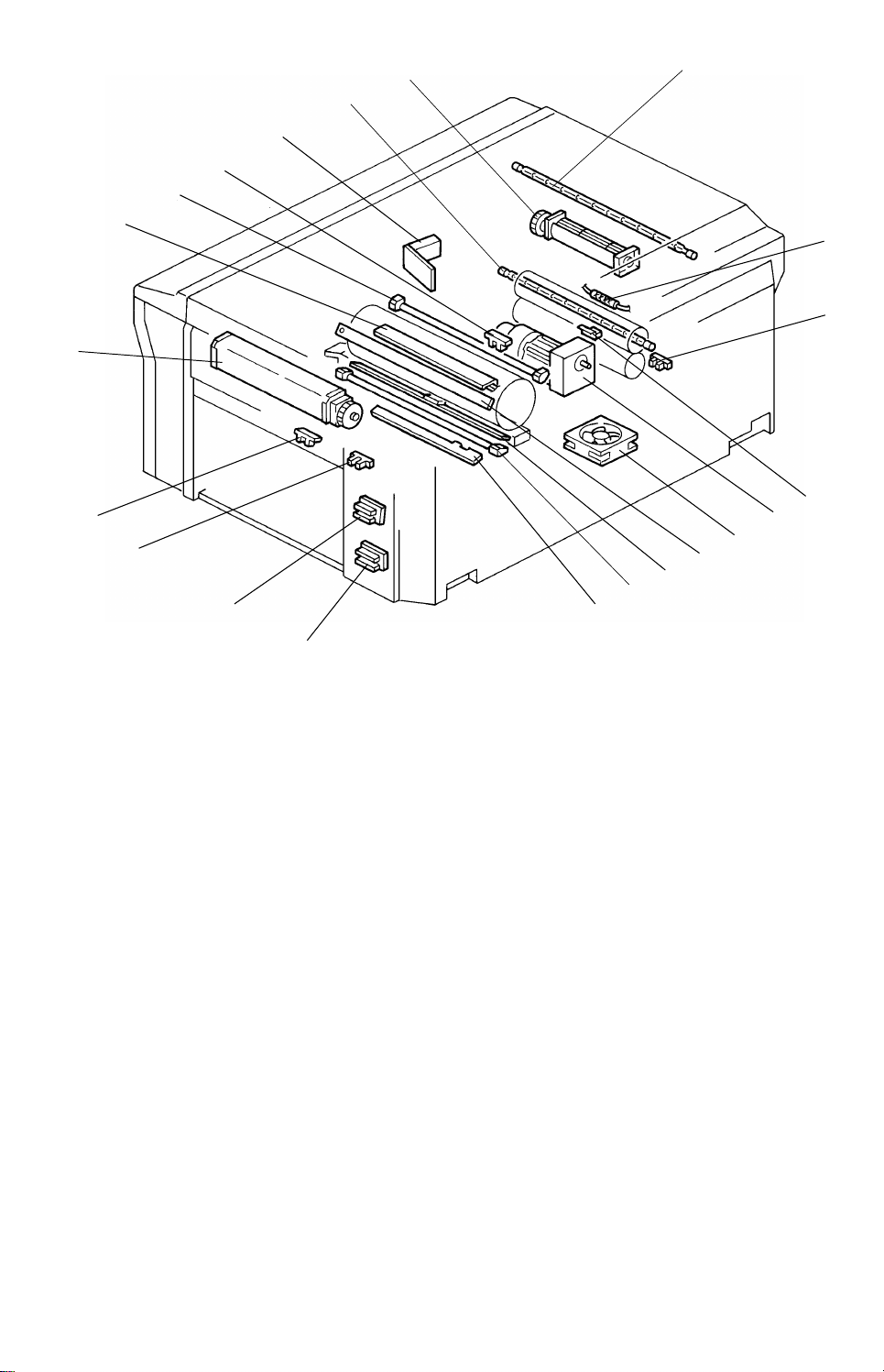
3939
545352
454647
59
58
57
56
55
40
41
42
43
51
44
50
49
39. Exposure Lamp
40. Thermofuse
41. Fusing Exit Sensor
42. Fusing Thermistor
43. Main Motor
44. Vacuum Fan
45. Erase Lamp
46. ID Sensor Board
47. PTL (Pre-Transfer Lamp)
48. Registration Sensor Boa rd
49. 2nd Cassette Paper S ize Se nso r
48
50. 1st Cassette Paper Size Sensor
51. By-pass Table Sensor
52. By-pass Paper End Sensor
53. Optics Cooling Fan
54. Drum Heater
55. QL (Quenching Lamp)
56. Lens Home Position Sensor
57. ADS Sensor
58. Fusing Heater
59. Exhaust Blower
- 17 -
Page 19
4.4 PAPER FEED AND REGISTRATION
Friction Pad
4.4.1 Mechanical Parts
1. Overview
In total this machine has fo ur feed stations. They are th ree cassette feed stations
and a by-pass feed station.
The 1st and 2nd feed statio ns ea ch use a size adjustable cassette , bu t the 3rd feed
station located inside the copier uses only an A3 cassette.
The capacity of each cassette is 250 sheets. The maximum pap er cap acity of the
by-pass feed station is 50 she ets.
All four feed stations use the feed rolle r and frictio n pa d syste m . On ly the by-pa ss
feed station uses a pick-up roller.
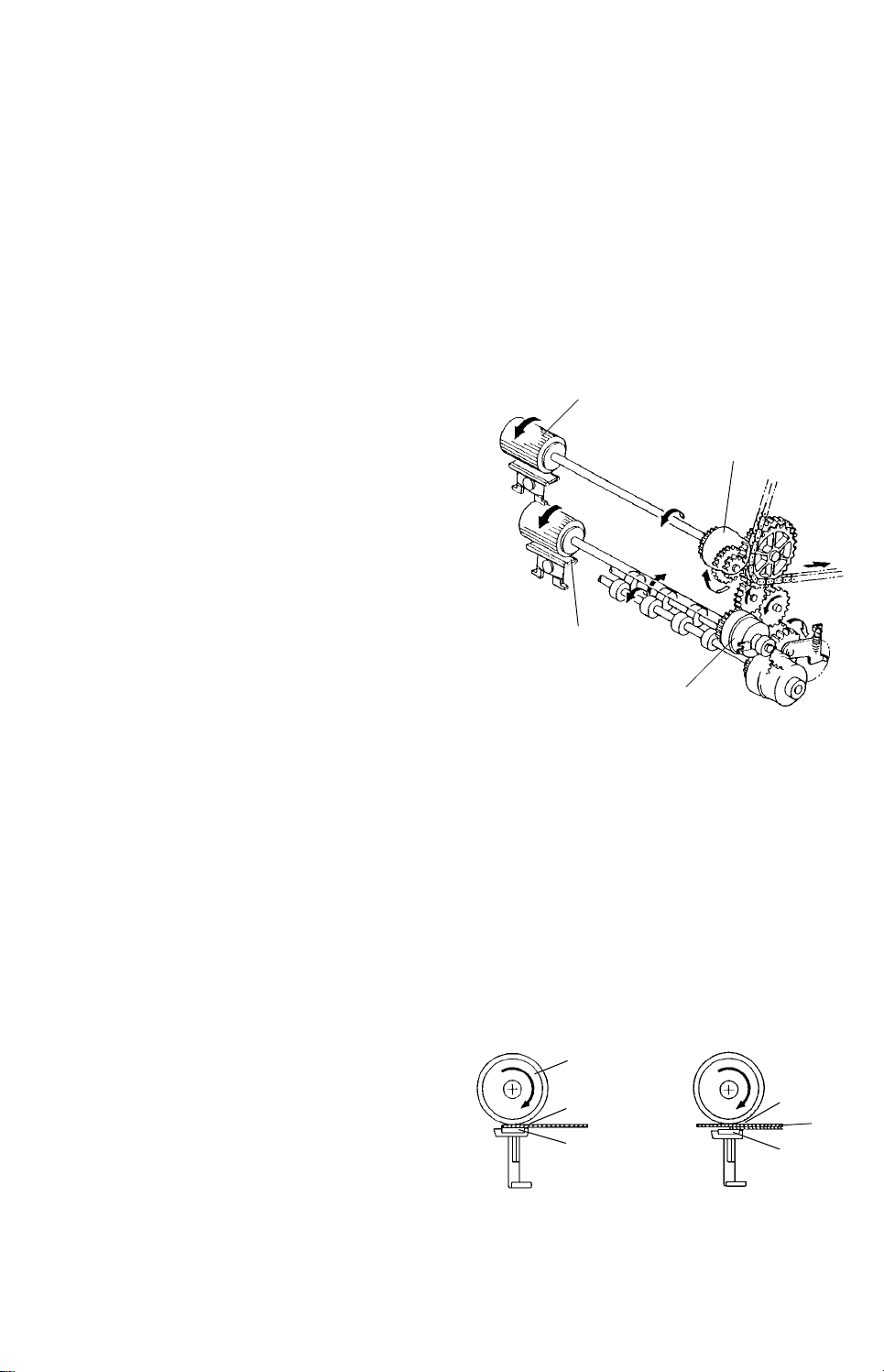
2. Feed System
1) Feed Roller
The CPU starts paper feed by energizing
the appropriate paper feed clutch (the
paper feed clutches are all magnetic
clutches).
The CPU turns on the paper feed clutch for
the required station, at a programmed time
after the Start key is pressed.
Upon receiving the sign al fro m t he
registration sensor, th e CPU tu rns of f the
paper feed clutch.
Feed Roller
1st Feed Clutch
2nd Feed
Clutch
2) Friction Pad Feed System
When a cassette is inserte d int o th e copier, the friction pad contacts the feed
roller (in the by-pass feed stat ion, it always contacts the feed roller). The friction
pad holder is mounted on one end of the swivel plate with a swivel screw, so it
automatically applies even pressure against the fee d roller and the copy paper.
The coefficients of frictio n are µ 1 > µ 2 > µ3.
<Single sheet
feeding>
Feed Roller
µ1
µ2
<Multiple sheet
feeding>
The coefficient of friction between
the friction pad and paper.
µ1
µ3
µ2
- 18 -
Page 20
3. Paper End Detection and Paper Size Detection
1) Paper End Detection
This machine uses a photointerrupter
sensor for paper end detection. The paper
end actuator, which is on th e same shaft as
the paper end feeler, pivots into the sensor.
2) Paper Size Detection
Paper size is detected by an array of five
photointerrupt ers in the cassette entrance.
The paper size sensors are actuate d by a
plate on the front of the cassette. Each
paper size has its own unique combina tio n
of notches in the act uator plate.
(For the front loading feed station , if paper
is detected, the copier aut oma tically
detects A3 size. The A3 casset te has a
paper size actuator in case it is used in the
1st or 2nd feeding stat ion for some reason.)
Size Detection Code
A3 B4 A4 A4R B5 B5R A5 A5R B6 B6R
1 ●●❍●❍●❍●❍●
2❍●❍❍●●❍❍●●
3❍❍●●●●❍❍❍❍
4❍❍❍❍❍❍●●●●
5❍❍❍❍❍❍❍❍❍❍
Paper Size Sensor
Actuator Plate
Detected: ❍
Not detected: ●
Other sizes are indicated as ❋ on the
operation panel.
- 19 -
Page 21
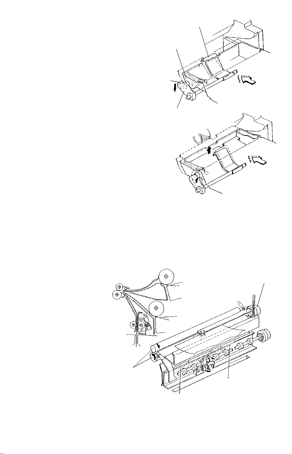
4. Paper Lift Mechanism
Cassette Arm
When a cassette is inserte d int o the copier, the
curved release guide s on th e sides of the
cassette press against the rollers on the
release levers and force the release levers
down. The release leve rs rotate the cassette
arm shaft, moving the cassette arm down and
out of the way.
When the cassette is fully se at ed , the release
guides allow the release leve rs to move back
up. The cassette arm then presses up the
cassette bottom plate until the paper contact s
the paper feed roller.
Release Guide
Release Lever
5. Registration
The registration rollers have two fu nct ions. One is to adjust the image leading edge
on the drum. Anothe r is to preve nt paper skew.
The registration roller is driven by the registra tio n clut ch and the switch -on timing of
the clutch can be adjuste d with DGS103 on the main board in 1 mm step s.
Registration
Clutch
Registr ation
Rollers
- 20 -
Page 22
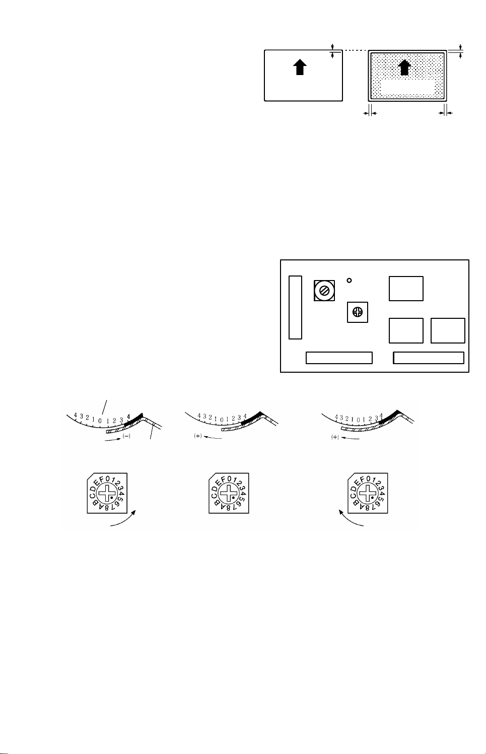
1) Registration Standard
Copy (A4)
(Main Board)
Drum
The registration standard is 0 ± 2mm. If it
is 0 mm, the paper lead edge and
original lead edge is the same . Bu t du e
to lead edge erase, the copy image has
a blank margin (3.5 ± 2.5 mm).
Original (A4)
a
bc
2) Registration Adjustment
Registration can be adju ste d by DGS103 on
the main board.
Origina l le ad
edge posi tion
de
a: lead edge erase (3.5 ± 0.5 mm)
b: registration (0 ± 2 mm)
c: lead edge blank margin
(a + b =3.5 ± 2.5 mm)
d, e: side margin (2 ± 2 mm at each side,
for full size copies. The total of both
side margins is less than 4 mm)
TP103
(PSEN)
DGS103
VR101
CN102 CN101
IC107
IC120 IC115
Paper
6. By-pass Feed Station
The by-pass feed table do es no t use the same feed mechanism as the other f ee din g
stations. It uses a pick-up rolle r in additio n to the feed roller and friction pad system.
To use a larger size than B4 at the by-pa ss fee d ta ble, the large cassette must be
installed in order to support the tra iling part of the paper.
When the by-pass feed table is opened, the pick-up soleno id tu rns on and off once ,
The by-pass feed table, add pap er, and inte rrupt indicators turn on, and the Start key
turns red.
- 21 -
Page 23
When paper is loaded onto th e by-p ass feed table, the paper end sen sor is
Feed Roller (2nd)
de-actuated and Sta rt key tu rns green.
When the Start key is pressed, the pick-up roller is lo were d by th e by-pass pick-up
solenoid to conta ct th e pa pe r stack. When the paper reaches the fee d rolle r, th e
pick-up roller moves up away from the pape r stack.
The size of copy paper is measured at the by-pa ss fee d sta tio n from the first copy as
follows. While the copy paper passe s under the registration sensor, the sensor
output changes from low to hig h. The CPU cou nt s the perio d of the high signa l and
calculates the paper len gth. The scanner return po sitio n corre sponds to this
calculated paper leng th.
When the by-pass feed table is opened, the by-pass table se nso r (a photo interrupter)
is activated and the copier enters by-p ass feed mode.
The by-pass feed mode is the same as interrupt mode. When the by-pa ss f ee d ta ble
is opened, the copier stores th e pre vious job settings in memory.
When the by-pass table is opened, the operator can use the 1st and 2nd cassette
stations before load ing pap er on to the by-pass feed table. Howe ver, whenever paper
is loaded onto the by-pass f ee d ta ble , other feeding statio ns can no t be select ed .
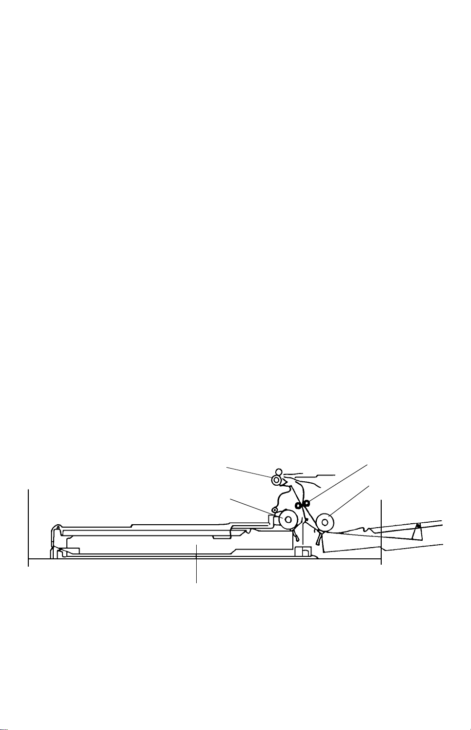
7. Front Loading Feed
The front loading fee d sta tion is located at the bottom of the copier. This is only an
A3 paper feeding station. The F/L tray pape r end senso r (a pho tointerrupter) on the
rear side plate detects bo th paper end and whether or not th e front loading station is
in position.
The direction of the pap er pa th is:
Feed Roller → Relay Roller → Registration Roller → T/S Corona Unit
Registration Roller
Feed Roller
Front Loading Cassette
Relay Rol ler
- 22 -
Page 24
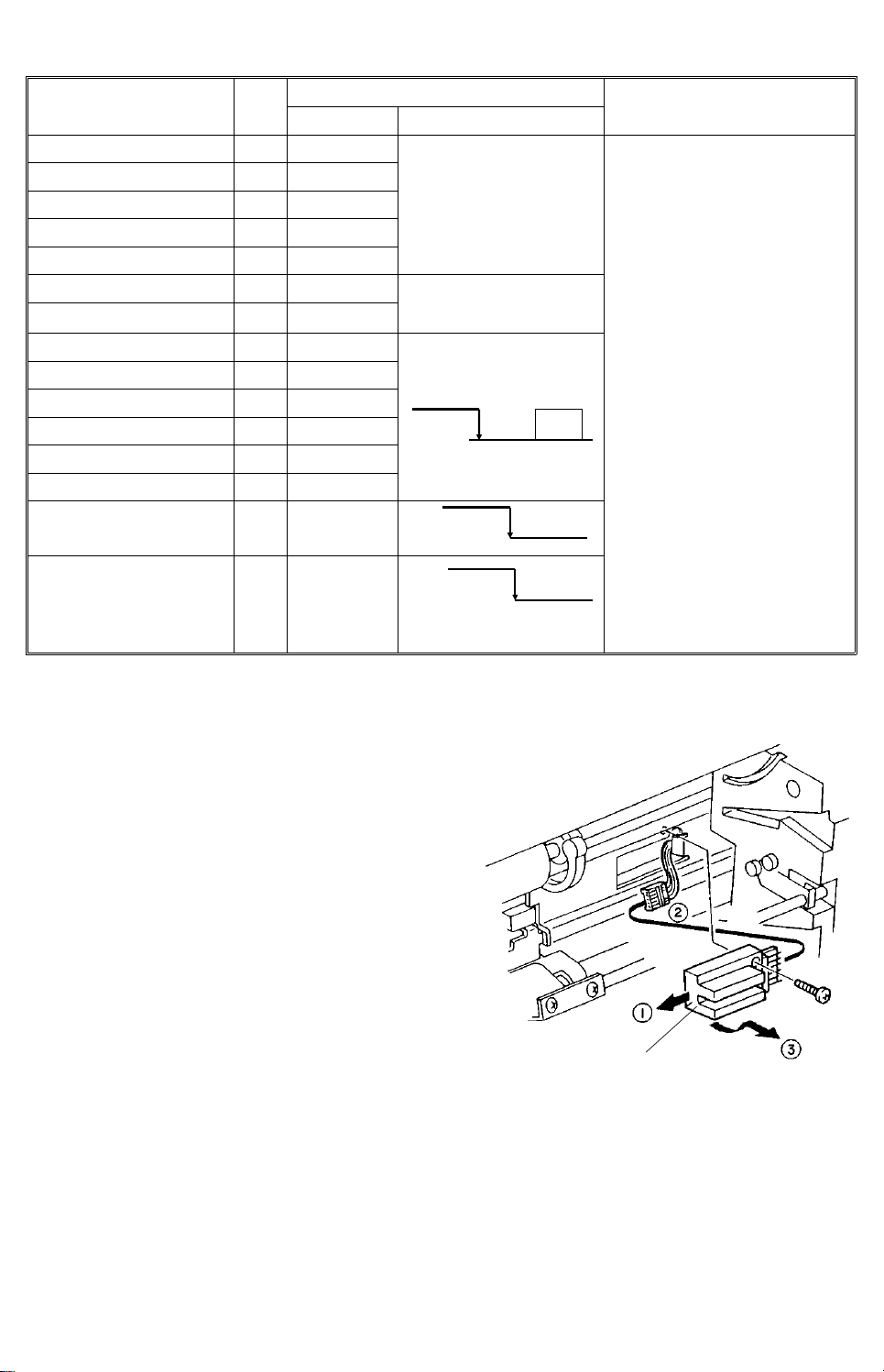
8. Electrical Control
ON
Signal I/O
Main Control Board
CN NO. Signal Level
Size 1 I 102–24B Detection: 5 V
Size 2 I 102–22A
Size 3 I 102–24A
No detection: 0 V
Size 4 I 102–22B
Size 5 I 102–25A
Paper End 1 I 102–23B Paper end:
Paper End 2
I 102–25B
detection
1st Feed MC O 101–5A
2nd Feed MC O 101–3A
By-pass Feed MC O 101–10A
24 V
F/L Feed MC O 101–2A
Relay Roller MC O 101–15A
Registration MC O 101–14B
By-pass Feed
Table Sensor
Registration Sensor
I 101–15A
closed
5 V
no paper
I 101–4A
open
paper
Scan Signal
T0 → 1st feed station
size detection
→ 1st feed station
paper end
detection
→ By-pass feed
paper end
detection
T1 → 2nd feed station
size detection
→ 2nd feed station
paper end
detection
→ By-pass feed
station table
open detection
4.4.2 Replacement and Adjustment
1. Paper Size Sensor Replacement (1st
and 2nd feed stations)
1. Remove the paper size sensor from the
sensor bracket (1 screw).
2. Remove the connector an d rep lace the
sensor.
Paper Size Sensor
- 23 -
Page 25
2. By-pass Feed Table Replacement
Upper By-pass Feed
Guide Plate
1. Open the by-pass fe ed tab le an d remove
the by-pass feed table hinges from the
positioning pins by pressing them inward .
2. Remove the by-pass feed table.
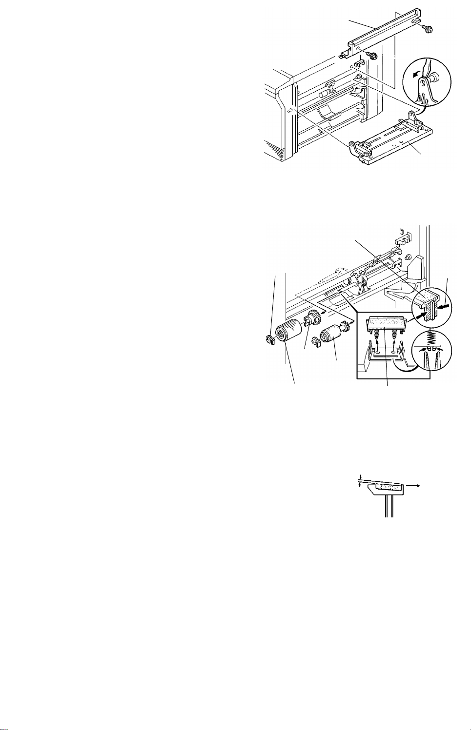
3. Feed Rollers and Friction Pads Replacement
NOTE: Replace the feed roller and th e
friction pad as a set to maintain a
good paper feed and separation
ability.
Snap Ring
1. By-pass Feed Station
1) Remove the by-pass feed tab le.
By-pass Feed
Table
Friction Pad
MT78
2) Remove the upper by-pass fee d gu ide
plate (2 screws).
3) Remove the pick-up roller, feed roller,
and gear (2 snap rings).
NOTE: When reinstalling the feed
roller, make sure that the hub is
positioned toward the rear on
Hub
Pick-up
Roller
Feed Roller
Friction Pad Holder
the shaft.
4) Remove the friction pad hold er by pressing the lower hooks using long no se
pliers.
5) Peel off the friction pad and stick a new
pad on the friction pad holder.
NOTE: Check that the friction pad is
A = 0.05 ~ 0.35 mm
(Front)
0.05 to 0.35 mm below the
surface of the front lip .
6) Grease both sides of the friction pad hold er with Mobil Temp 78.
7) Reinstall the friction pad holde r and the by-pa ss fee d ta ble .
NOTE: 1) Do not touch the surface of the new friction pad with oily fingers.
2) Be careful not to damage the pressu re sprin gs.
3) The lip side should be positio ned towards the outside of the
machine.
- 24 -
Page 26
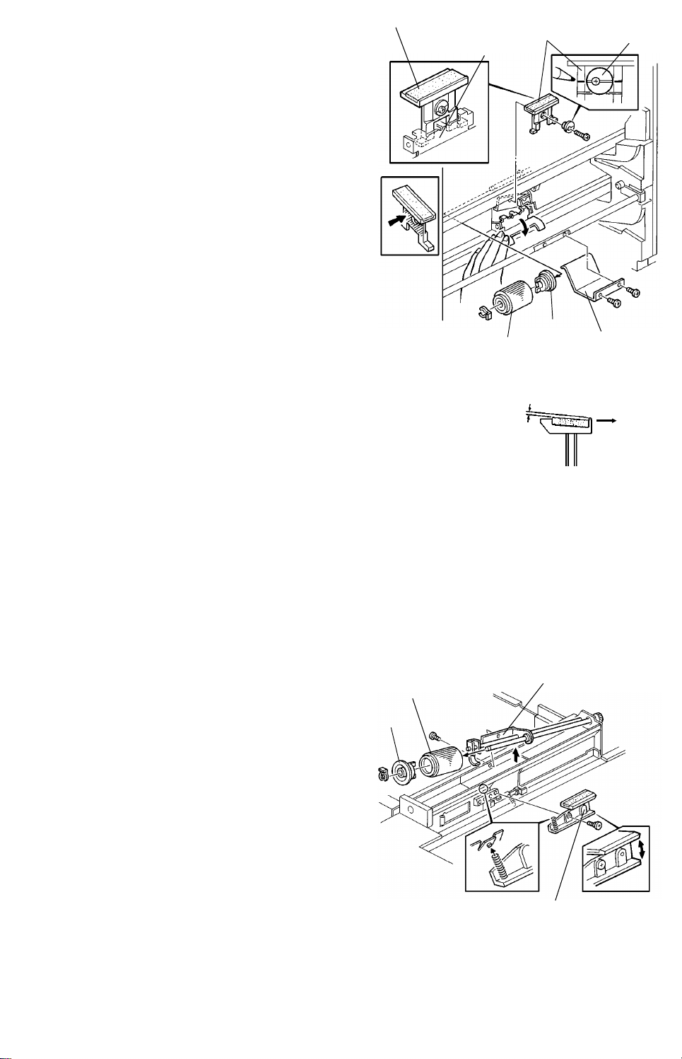
2. 1st and 2nd Feed Stations
Pad Positioning
Mechanis m
Friction
Pad Holder
Hub
1) Remove the feed roller and hub (1
snap ring).
NOTE: When reinstalling the feed
roller, make sure that the hub
is positioned toward th e rea r
on the shaft.
2) Remove the cassette arm (2 screws).
3) Mark the position of the eccentric cam
groove on the friction pad holder.
Friction Pad
Eccentric
Cam
4) Remove the friction pad holder (1
screw and 1 eccentric cam).
5) Peel off the friction pad and stick a new
pad on the friction pad holder.
NOTE: Check that the friction pad is 0.05
to 0.35 mm below the surface of
the front lip.
6) Clean and grease the swivel surface of
the friction pad holder with Mobil Temp 78.
7) Reinstall the friction pad holder.
NOTE: Be sure the legs of the friction pad holder are positioned und er th e
spring loaded pad positio nin g mechanism.
The eccentric cam should be secured in the origin al po sitio n
referring to the mark made in step 3).
MT78
Feed Roller
A = 0.05 ~ 0.35 mm
Cassette Arm
(Front)
4. F/L Feed Station
1. Pull out the F/L tray and remo ve th e A3
cassette.
2. Remove the screw securing the feed roller
bracket.
3. Remove the F/L feed roller (1 snap ring).
NOTE: When reinstalling the feed roller,
make sure that the hub is
positioned towa rd th e front on the
shaft.
4. Remove the friction pad assembly (1
stepped screw).
- 25 -
Feed Roller
Hub
Feed Roller
Bracket
Friction Pad
Assembly
Page 27
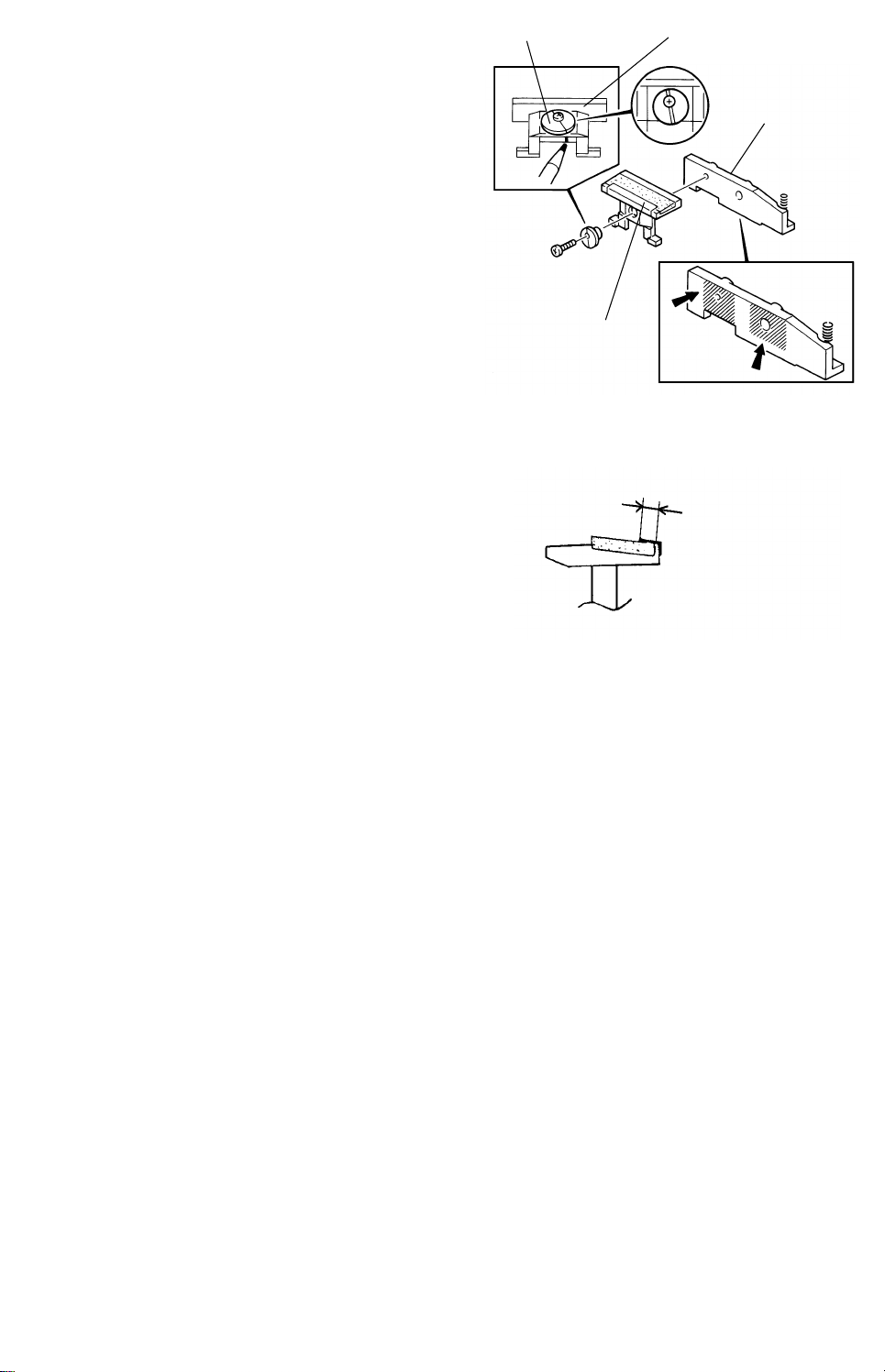
5. Mark the position of the eccentric cam
MT78
P
groove on the friction pad holder.
Eccentric Cam
Friction Pad Holder
6. Remove the friction pad holder f rom th e
holder bracket (1 screw and 1 eccentric
cam).
7. Peel off the entrance mylar and the friction
pad and stick new ones on the friction pad
holder.
NOTE: Check that the friction pad is 0.05
to 0.35 mm below the surface of
the front lip.
Make sure that the overlapping
length of the entrance mylar on the
friction pad (P) is 2.5 to 3 mm.
Holder Bracket
Entrance Mylar
2.5 ~ 3.0 mm
8. Clean and grease the swivel surface of the friction pad holder with Mobil Temp
78.
9. Reinstall the friction pad hold er on the hold er bra cket .
NOTE: The eccentric cam should be secure d in the original position refe rring to
the mark made in step 5).
10. Clean and grease the swivel surface of the holde r b racke t with Mo bil Temp 78.
11. Reattach the friction pad assemb ly to the F/L fee din g sta tio n.
NOTE: Be sure the legs of the friction pa d ho lde r are po sitio ne d unde r the
spring loaded pad positioning mechanism. Make sure that the pressure
spring is properly positioned and the frictio n pa d asse mbly swivels
smoothly.
- 26 -
Page 28
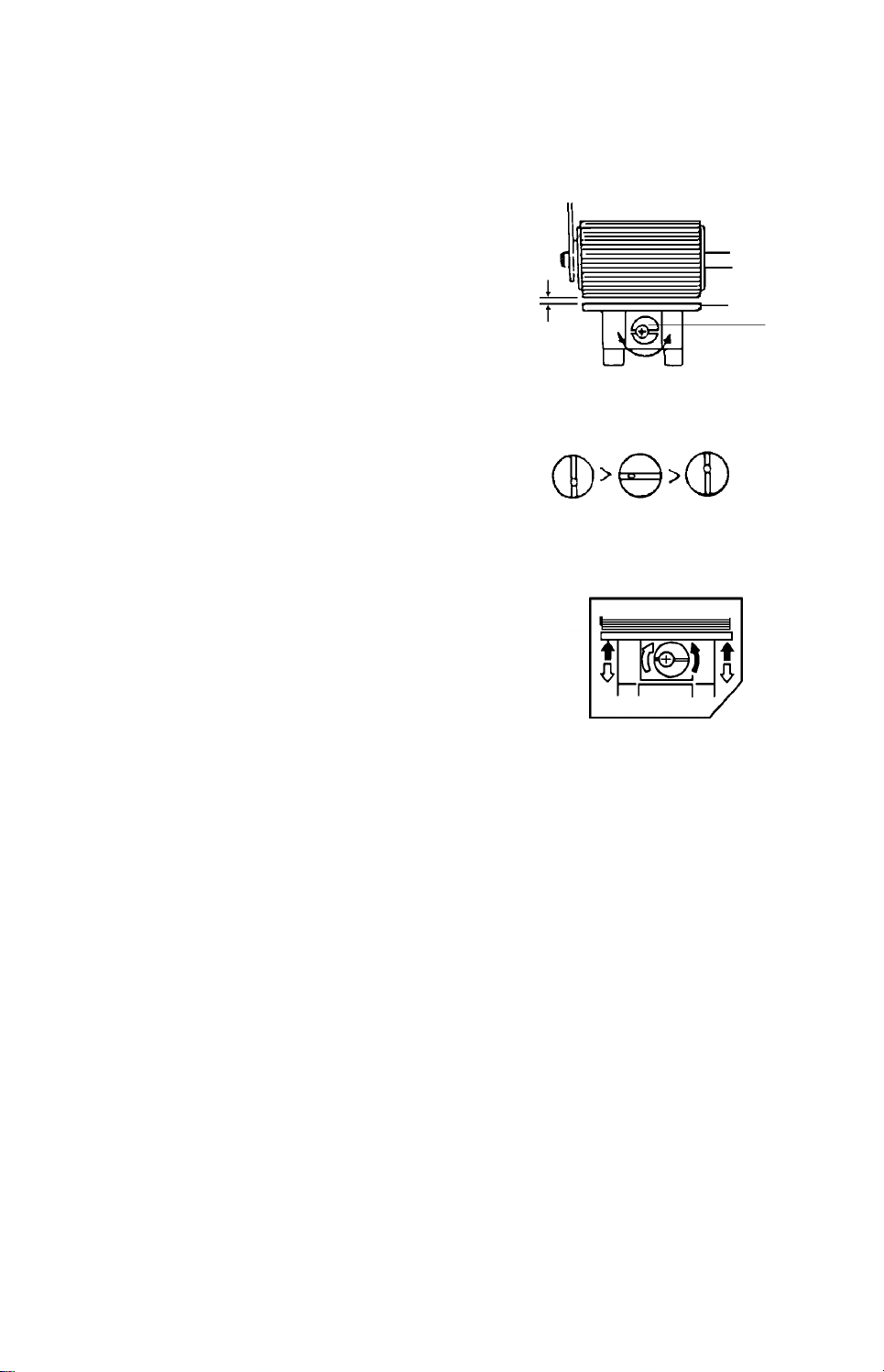
5. Friction Pad Pressure Adjustment
(fig. 2)
NOTE: This adjustment is require d when multifeeds or misfeeds occur with th e
customer’s brand of paper.
If replacement of the fee d rolle r and the frictio n pa d does no t solve the
problem, do the following adjustment.
1. Remove the cassette.
2. Turn the eccentric cam [A] to adjust the
friction pad pressure as shown in figu res 1
and 2.
NOTE: If the eccentric ca m groove is
aligned vertically, the gap between
the feed roller and the friction pad
will become narrower or wider as
shown in figure 3.
• When multifeed occurs, make
the gap narrower.
• When misfeed occurs, make the
gap wider.
[A]
(fig. 1)
Narrow Normal Wide
(fig. 3)
- 27 -
Page 29

4.5 OPTICS
2nd Mirror
Scanner Motor
4.5.1 Mechanical Parts
1. Overview
Exposure La mp
3rd Mirror
Reflector
1st Mirror
Lens
4th Mirror
Toner Shield
Glass
During the copy cycle, an image of the original is reflecte d onto the drum surface via
the optics assembly as follows.
Light path:
Exposure Lamp → Original → First Mirror → Second Mirror → Third Mirror → Lens
→ Fourth Mirror → Ton er Sh ield Glass → Drum
(When the exposure lamp is positioned close to the far left, it is at the home position.)
This model has ten standard repro du ctio n ratios: six reductions, three enla rge ments,
and full size. In addition, it has a zoom fu nct ion.
The user can change th e rep roduction ratio in one perce nt st eps f rom 50 % to 200 %.
This machine has an automatic ima ge control system in which the copier comput es
the correct image density and adjusts the deve lop ment bias as a result of measuring
the original background densit y using the ADS sen sor.
2. Scanner Drive
1st Scanner
2nd Scanner
Scanner Drive
Wire
Damper wheel
Scanner Home
Position Sensor
- 28 -
Page 30
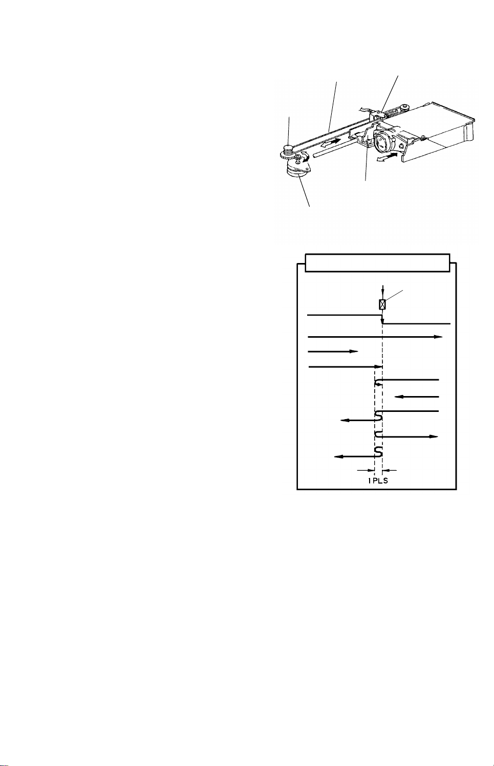
This model uses a dc servomotor to drive th e scanners.
Lens Drive Wire
Full Size
(Reduction)
The scanner motor chan ge s the scann er spe ed dep en din g on the reproduction ratio.
3. Lens/Mirror Positioning
The lens motor (a stepping motor) changes the
lens and 2nd scanner posit ion in accord an ce
with the selected rep roduction ratio to provide
Lens Drive
Pulley
Lens Home
Position Sensor
the proper optical dista nce between the lens
and the drum surface.
1. Lens Positioning
The output gea r o f th e lens motor engages
the gear of the lens drive pulley directly.
Lens Drive Bracket
The lens drive wire is wrapped around the
lens drive pulley and is connected to the
Lens Motor
lens drive bracket. As the lens mot or is a
stepper motor, the rotation of the lens drive
pulley moves the lens back and forth in
discrete steps.
The lens home position sensor informs the
optics CPU (IC403) when the lens is at the
Lens Movement
Lens H.P.
Sensor
(Enlargement)
full size position (home position). The
optics CPU determines the lens stop
position in reduction and enlargement
modes by counting the number of steps the
motor makes.
When the reproduction rat io is chan ged,
the lens moves directly to th e sele cted lens
position.
When the lens moves from one
enlargement ratio to another or from one
reduction ratio to ano th er, it does not
moves to the home position.
- 29 -
Page 31

2. Light Shading Mechanism
Shading
Cam Plate
The machine is designed so tha t the
intensity of the light across the drum is
uniform at 100% reproduct ion . However,
the intensity of the light striking the drum
tends to increase toward the edges when
the reproduction rat io is d ecre ased, as a
result of the change in position of the le ns.
For this reason, a light shading mechanism
has been installed to pre ven t un even
illumination when making reduced copies.
When the lens moves in the reduction
direction, the groove cams move th e
shading plates closer together.
The plates block part of the lig ht passing
through the lens to keep the intensi ty of the
light on the drum even.
3. 2nd Scanner Drive
In order to provide the proper optical
distance between th e original and the lens,
this model uses a stepper moto r to move
the second scanner.
A separate motor is used because the
second scanner must tra vel a lon g distance
in order to accommodat e a wide ra ng e of
reproduction ratios.
When the second scanner moto r drives the
second scanner drive pulley, the wire
pulleys rotate as shown by the black
arrows (➡).
So, the second scanne r moves in the
direction of the white arrow (ð).
Shading Plate
2nd Scanner
Drive Pulley
Groove Cam
2nd Scanner
2nd Scanner
Pulley
- 30 -
Page 32

When the second scanner moves fro m enlargement to reduction or fro m re duction to
enlargement, it does not move to the home position.
NOTE
1) When the zoom key is pressed, the buzzer rings at reproduction ratios between
50 ~ 155% but does not ring at 15 6 ~ 2 00 % an d the speed of the reprod uction
ratio indicator is higher.
2) The effective original area is restricte d at repro du ctio n rat ios of 156 ~ 200% . This
causes partial enlargeme nt beca use the lens rest ricts exposure lamp movement.
ex): Effective origina l area at 200% enlargement.
Copying can be in the range as sho wn.
With 200% enlargement, an A5 original
can be copied onto A3 paper but the
trailing 84 mm does not appear on the
copy image. So, the trailing 42 mm of the
A5 original is not copied.
Formula of the effective vertical
enlargement are a:
180
– 180 M + 438
M
Where M: reproduction ratio
(200% is 2)
180: focus distance
438: maximum amount of
movement
- 31 -
Page 33

4. Automatic Image Density Sensing (ADS)
Manual image
density mode
This copier has an ADS system for good quality copy images. Light from the
exposure lamp is reflected from the original and travels to the ADS sen sor on the
lens base via the mirror.
Sampling starts 3 millimeters from the leadin g edge of the orig ina l in full size
mode.
The length and width differ for each reproduct ion ratio.
The photosensor circuit converts the light intensity to a voltage.
The detected voltage is amplified and sent to th e main board.
It then computes the background density of the original from the maximum
sample voltage and changes the development bias accordingly.
The exposure lamp volta ge is constant (equal to the volta ge at the manual
density level 4) regardless of the image density of the original.
Original scale
1) Comparison of the manual image
density key and the auto ima ge
density key.
When the manual image density
mode is selected, the exposure lamp
voltage and the development bias
for each level are as shown to the
right.
Only the exposure lamp volta ge
varies according to the in pu t.
This is based on preventio n of ID
level decrease at high manual image
density levels.
Output voltage + Development Bias Control
➀ ➁ ➂ ➃ ➄ ➅ ➆
V0-4
0
V
V0+6
V
0+11
V
0+16
0+23
V
V
0+23
(V0 is the voltage of the lamp at the
manual image density level 2. )
- 32 -
Page 34

Manual image
16 Pitch
R: 1 mm Pitch
0 7 F
density mode
level
1 320 V
2 290 V
3 260 V0+6
4 260 V
5 260 V
6 260 V
7 320 V
B VVDE VB V
V
0–4
0
0+11
0+16
0+23
0+23
~ 1.65 440 V0+11
1.65~2.16 380 V
2.16~2.65 320 V
ADS mode
2.65 ~ 260 V
0+11
0+11
0+11
Drum temperature: 30°C
VB: Development bias voltage
V: Lamp voltage
VDE: ADS input voltage
(V0 is the voltage of the lamp at
the manual image density level 2. )
2) Function of DPS102 on th e Main Boa rd
• DPS102
No.12345678
ON
OFF
Nor-
mal
large
á
ON
OFF
â
small
ON ON
ON OFF ON OFF
OFF ON OFF ON
OFF OFF OFF OFF
OFF OFF
OFF ON OFF ON
ON OFF ON OFF
ON ON ON ON
TB: 0.2%
Pitch
large
á
ON
OFF
â
small
ON ON
OFF OFF
E: 0.8 mm
Pitch
Nor-
mal
(OFF)
TB: Vertical magnification
E: Lead edge erase
R: Lead edge registration
DGS103
(Scanner speed)
- 33 -
Page 35

4.5.2 Replacement and Adjustment
Left Scale
1. Exposure Glass Removal
1. Take off the left scale (2 short screws).
2. Grasp the left edge of the exposure glass
and lift it up slightly. Slide the other edge
out from under the right glass holder.
Remove the exposure glass.
NOTE: Be sure that the two screws a re
M4 x 6 but others are M4 x 8.
2. Exposure Lamp Replacement
CAUTION: Be sure that the main switch is
turned off before replacement.
1. Remove the exposure glass.
2. Move the first scanner to the position
where the rear frame is cut out.
Exposure Glass
Reflector Cover
Release Lever
3. Remove the reflector cover (2 screws).
4. Wrap a strip of paper around the expo sure
lamp as shown.
5. Press the release lever on the front lamp
terminal as shown and take out the lamp .
(Do not touch the reflect or or the new
exposure lamp with your bare hand s; use a
strip of paper as shown.)
NOTE: The blister on the lamp must poin t
toward the mouth of the reflector
as shown.
Blister
Exposure La mp
Reflector Cover
Reflector
- 34 -
Page 36

3. Exposure Lamp Positioning
Filament
CAUTION: Be sure that the main switch is
turned off before adjustment.
1. Remove the exposure glass.
2. To correct the position of the filamen t in
parallel with the sight hole, tu rn the
adjusting screw.
NOTE: 1. Do not adjust vertically using
the adjusting knob.
2. If the adjustment is incorrect ,
uneven image density or dirty
background will appear on the
copy image.
4. 2nd and 3rd Mirror Replacement
Reflector Cover
Adjusting Screw
Exposure
Lamp
2nd Mirror
Front Spring
Plate
1. Remove the front spring plate.
2. Carefully pull the mirror towards the front.
NOTE: Be careful not to dro p rear spring plate.
Rear Spring Plate
2nd Mirror
- 35 -
Page 37

3. Take off the protective sheet only a t both ends of th e mirror.
Sub Reflector
Upper
Seal
4. Check that the rear sprin g pla te is set properly.
5. Insert the mirror into the front side plate cut ou t and set it on the rear spring plat e
properly.
6. Locate the bottom of the front spring plate and rotate the to p of the spring into
position.
NOTE:
1. Install the mirrors with the
reflecting surface facing
2. Attach the spring pla te to
the lens as shown.
Spring plate
Reflecting
surface
Spring plate
7. Check whether the mirrors vibra te as sh own .
If so, reinstall the sprin g pla tes after bending them.
NOTE: To prevent vibration, replace the
spring plates whenever the mirrors
are replaced.
8. Remove the rest of the protective sheet.
5. 1st Mirror Replacement
the nonreflecting surface.
Check vibration
1. Remove the top cover (12 screws).
2. Remove the sub reflector (2 screws).
3. Remove the upper seal at th e front side.
4. Free the lamp harness fro m t he bracke t (1
screw).
5. Lift the 1st scanne r through the positio n
where the front frame is cut out.
6. Remove the front spring plate.
7. Pull the mirror towards the front of the
machine while holding the rear sprin g plate
with your fingers.
8. Remove the rear spring plate.
9. Take off the protective sheet only at both
ends of the mirror.
- 36 -
Rear Spring Plate
Front Spring Plat e
Lamp Harness
Page 38

10. Position the rear spring pla te and hold it with you r f ing er while in sert ing the mirror
Spring plate
into the rear spring plate through the ho le in the front of the scanne r.
NOTE: 1. Install the mirror with the reflecting surfa ce up permost .
2. Install the mirror with th e cutout part facing down.
3. Attach the sprin g plate to the non reflect ing surface.
Reflecting surface
Cutout part
11. Position the front spring plate.
12. Make sure that the mirror do es not vibrate.
13. Remove the rest of the protective sheet.
14. Reinstall the othe r co mpo ne nt s.
- 37 -
Page 39

6. Scanner Drive Wire Replacement
Wire Clamp
Damper Wheel
Scanner Drive Wire
Tension Spring
1. Turn off the main switch.
2. Remove the platen cover, the mounting studs, and the top cover.
3. Remove the left scale (2 sho rt screws) an d th e exposure glass.
4. Remove the rear cover (3 screws) and lower th e PCB plate (2 screws).
5. Remove the damper wheel.
6. Loosen the wire clamp screw.
7. Remove the lamp stabilizer bracke t (1 screw).
8. Move the 2nd scanne r to the return position.
9. Unhook the tension spring and remove the spring. Take ou t th e old wire.
10. Remove the home position sensor bracket (1 screw).
- 38 -
Page 40

WP2
(2nd Scanner Pulle y)
Scanner Drive Pulley
7)
Damper Wheel
WP3
5)
6)
WP4
11)
3)
WP5
WP6
10)
9)
Wire Clamp
4)
8)
Bead
2) Long End
WP1
1) Short End
11. Run the scanner drive wire over t he pulle ys in the follo wing order.
1) Attach the tensio n spring to the short end eyele t an d ho ok the other end of
spring to the cut out in the optics frame temporarily.
2) Set the bead of the scanne r drive wire in the holes in the 2nd scanner drive
pulley with the short end located at the lower side (WP1).
3) Two and half turns (WP1)
4) Outer track (WP2)
5) Lower side (Wire Clamp)
6) Lower track (WP3)
7) Inner track (WP4)
8) Three and half turns from lower to upper (Scanner Drive Pulley)
9) Outer track (WP4)
10) Lower track (WP5)
11) Inner track (WP2)
12) Outer track (WP6)
12. Set the long end eyele t in th e ho ok of the ten sion spring.
13. Reset the damper wheel.
14. Rotate the scanner drive pulle y and ma ke sure that the scanner drive wire moves
smoothly and that the r e is no ove rlapping on the scanner drive pulle y.
- 39 -
Page 41

7. Wire Clamp Positioning
When the second scanner is 52 mm from the left opt ics frame , secure the first
scanner wire clamp so that its end is positioned about 1 mm inside the home position
sensor.
When the copy image is enlarged, move th e wire clamp to the lef t, and when the
copy image is reduced, move the wire clamp to the right.
Standard
Scanner H.P.
Sensor
Horizontal magnification : ±0.5%
Vertical magnification: ±1%
Vertical magnification can be
adjusted by DPS102 on the
optics control board.
Wire Clamp
Scanner H.P.
Sensor
Left Optics
Frame
8. Scanner Motor Replacement
1. Turn off the main switch.
2. Remove the platen cover, the mounting studs, and the top cover (8 screws).
3. Remove the left scale (2 sho rt screws) an d th e exposure glass.
4. Remove the rear cover (3 screws) and lower th e main board bracket (2 screws).
5. Tape the scanner drive pulley and the wire pulle ys A .
6. Loosen the scanner drive pulley (2 Allen screws).
7. Remove the scanner drive pulley from th e motor shaft.
8. Remove the nylon wire clamp on the left side of the toner supply clutch bracket.
9. Remove the scanner motor (4 screws and 2 con nectors).
Scanner Motor
Wire Clamp
Scanner Drive
Pulley
- 40 -
Page 42

9. Lens Motor Replacement
Wire Saddle
Left Fork
1. Remove the fusing unit an d th e left inner
cover (2 screws).
2. Remove the rear cover (3 screws) and
lower the main board bracket (2 screws).
3. Disconnect the lens motor connector
(yellow) and free the harness from the wire
saddle.
4. Remove the left cover (4 screws) and the
exit guide plate (2 screws).
5. Remove the lamp regulator (2 screws and
2 connectors).
Lens Motor
Harness
Exit Guide
Plate
Lamp Regulator
6. Remove the left scale (2 short screws) and
the exposure glass.
7. Remove the lens housing cover (3 screws)
and remove the lens drive wire from the
pulleys by removing the te nsion spring.
NOTE: When reinstalling the lens drive
wire, do the following steps
referring to the illustration:
1) Set the bead of the lens drive
wire in the left fork and wrap the
wire around the lens drive
pulley for three and half turns.
2) Run the wire on the tension
pulley and set the wire bead in
the right fork.
3) Set the tension spring.
8. Move the scanners to the return position
and take out the lens drive pulley from the
motor shaft (1 E-ring).
Lens Drive
Pulley
Lens Housing Cover
Fusing Upper
Guide Plate
Tension Spring
Right Fork
Lens Drive
Wire
Tension
Pulley
9. Remove the screws from the front and rear
side plates (2 for the front and 1 for the
rear) which secure the fusing upper guide
plate.
10. Remove 3 screws that secure the lens
motor assembly to the optics base plate.
11. Take out the lens motor assembly f rom th e
left side while lowering the fusing upper
guide plate.
- 41 -
Lens Motor
Lens Drive
Pulley
Motor
Bracket
Lens Drive
Pulley
Page 43

12. Remove the lens motor cover from the motor assembly (1 screw).
13. Remove the lens motor from t he bracke t (2 screws).
14. Install the new motor on the motor bracket and reassemble the copier.
10. Light Intensity Adjustment
(Exposure Lamp Voltage Adjustment)
NOTE: a. This adjustment should be
done when the rest time
compensation of the bias
voltage is 0V. If the main power
switch has just been turned on,
make ten copies before
proceeding to check the light
intensity. The test copy should
be made 10 seconds after the
tenth copy was made.
VR1
b. ADS voltage adjustme nt must
be done after light intensity
adjustment.
Lamp Regulator
Board
ADJUSTMENT STANDARD:
Level 2 of the gray scale on the OS-A3 chart sho uld be faintly visible on the copy
when the 4th level of the density control is selected.
1. Clean the optics (mirrors, lens, reflect ors, expo sure glass, toner shield glass).
2. Turn on the main switch and allow it to warm up.
3. Set the image density level at the No. 4 position and make 11 test copies of the
OS-A3 test chart.
4. Confirm that the second level of the gray scale is faintly visible on the 11th copy.
If the light intensity is not correct , pro cee d to step s 5 and 6.
5. Remove the left cover (4 screws). (If a sort er is installed, the sorter and the sort er
adapter should be remo ved .)
6. Adjust VR1 on the lamp regulat or bo ard to ach ieve prop erly illumin ated copies.
NOTE:
• If the test copies were made within 3 minutes after making the
previous copies, check the ligh t intensity on the 4th copy.
• If it is over 3 minutes, check the light intensity on the 6th cop y.
- 42 -
Page 44

11. ADS Voltage Adjustment
NOTE: 1. ADS voltage adju stme nt is required in the following cases.
1) Exposure lamp voltage adjustment.
2) Exposure lamp replacement.
3) When using ADS mode, abnormal co py imag e ap pears.
4) Main board replacement.
1. Place more then 5 sheets of A3 pape r o n th e exp osure glass.
2. Turn on DIP SW101-1 on the main board (free run mode).
3. Set SP mode (88) to "11". (Ref er to the SP mode access procedure. )
4. Leave SP mode.
5. Access ADS input mode as shown.
Interrupt key → "4" key → Interrupt key
6. Press the Start key.
7. Adjust the ADS voltage to 3.0 ± 0.06 V as displayed in the ma gnification indicator
of the operation pa ne l by using VR102 on the main board.
NOTE: 1. Remove the 1st cassette from the copier to make full scans so that
the adjustment will be easy.
2. Adjusting VR10 2 sho uld be done based on the dat a af ter 3 scans.
3. The ADS data is based on the da ta when the exposure lamp moves
from the home position to the center of exposure glass.
4. After the adjustment, be sure that the SP mod e an d DIP SW a re
reset. (Set SP mode (88) to "10".)
5. When adjusting ADS volt ag e, set the image density mode to
"automatic image density mode".
- 43 -
Page 45

4.6 AROUND THE DRUM
4.6.1 Mechanical Parts
1. Overview
The drum drive belt turns the drum pulley when the main mot or is on. The rear drum
flange is secured by a screw on th e dru m sh af t an d the drum spring presses the
drum onto the rear drum flange.
Drum
Drum Spring
Drum Shaft
Rear Drum Flange
Drum Drive Belt
Drum Drive Pulley
So, the rotation is transmitted from the drum drive pu lley to the drum sha ft and then
through the rear drum flange to the drum.
2. Drum Charge
Power Pack C/B
In the dark the corona wires ge ne rat e a coro na
of positive ions when the C/B power pack
applies a high positive voltage (+5.0 kV ~ 7.5
kV).
Charge
Corona Unit
The selenium coating receives a uniform
positive charge (700 ± 50 V) as it rot ates past
the corona unit.
The main motor fan provid es a smoo th flow of
air to the interior of th e cha rge corona unit to
prevent uneven build-up of positive ions.
The diameter of the charg e coro na wire is 0.08
mm and the wire surface is coated with carbon.
The wire cleaner cleans off any particle s on th e
wires when someone pulls out the coro na unit
and pushes it back.
- 44 -
Main Motor Fan
Wire Cleaner
Page 46

3. Erase Lamp
The erase lamp illuminates the area of the cha rge d dru m surface that will not be
used for the copy image.
The erase lamp reduces to ne r consu mption and the drum cleaning loa d.
Erase Unit
Charged Area
Charge
Corona Unit
Original Lead Edge
Front Endbloc k
Cover
[Density Detection Cycle]
Left Scale
Sensor Pattern
Original Lead
Edge
Sensor
Pattern
Origina l Le ad
Edge
Exposure Glass
Toner Image
Original
Paper
Sensor Pattern
Charged Area
A: Lead Edge Erase Margin --- 3.5 ± 0.5 mm
B: Side Margins --- 2 ± 2 mm each
(For full size copies the total of both side
margins is less than 4 mm.)
LO: Original Image width
LC: Charged width on the Drum
EL: Lead Edge Erase
ES: Side Erase
R: Lead Edge Registration --- 0 ± 2 mm
A+R:Lead Edge Blank Margin --- 3.5 ± 2.5 mm
The erase lamp consists of a line of 64 LEDs ext en din g across the full width of the
drum.
The erase lamp performs lea d ed ge erase and sid e era se.
The erase lamp unit also has two thermistors: TH-1 and TH-2.
Both of these thermistors detect th e temperature around the drum.
TH-1 determines the proper rest time compe nsa tio n, and TH-2 controls th e
development bias voltage.
- 45 -
Page 47

1. Lead Edge Erase
The entire line of LEDs turns on when the main mot or tu rns on . The y stay on unti l
the erase margin slight ly overlaps the lead edge of the orig ina l ima ge area on th e
drum (Lead Edge Erase Margin).
This prevents the toner densit y sensor pattern from being develo ped on every
copy cycle and prevents the edge of the orig ina l from ap pearing on the copy
image. The width of the lead edge blank margin can be adju sted with DIP
SW102-5, 6 and -7 on the ma in board.
During image density detection cycles (once eve ry ten cycles), th e cen ter block
of erase lamps turns off long enoug h fo r t he senso r p at te rn to be developed.
2. Side Erase
Based on the paper size and on the reproduction ratio, the LEDs turn on in pairs
(one on each side) to discharg e th e drum potential on both sides. For A3
copying, the drum pote ntial is not erased by the erase lamp but by the charg e
corona end blocks.
3. Erase Lamp
32 LEDs
Erase lamp segments are turned on and off based on the cassette data and
reproduction ratio da ta as shown on the next page.
For full size and enlargement copyin g, on/ of f switch ing is based only on cassette
data. For reduction cop ying, it is based on an OR circuit between casse tte data
and reproduction rat io da ta .
- 46 -
Page 48

4. Erase Data
• Cassette Data (0: off, 1: on)
Cassette Size 1 2 3 4 5 6 7 8 9 10 11 12 13 14 15 16 17
A3 00000000000000000
B4 11110000000000000
A4 00000000000000000
A4 Lengthwise 1 1 1 1 1 1 1 1 1 1 0 0 00000
B5 11110000000000000
B5 Lengthwise 1 1 1 1 1 1 1 1 1 1 1 1 10000
A5 11111111110000000
A5 Lengthwise 1 1 1 1 1 1 1 1 1 1 1 1 11110
B6 11111111111110000
B6 Lengthwise 1 1 1 1 1 1 1 1 1 1 1 1 11110
00000000000000000
Reproduction Ratio Data (0: off, 1: on)
•
Ratio (%) 1 2 3 4 5 6 7 8 9 10 11 12 13 14 15 16 17
50 ~ 53 11111111111111110
54 ~ 57 11111111111111100
58 ~ 60 11111111111111000
61 ~ 63 11111111111110000
64 ~ 67 11111111111100000
68 ~ 70 11111111111000000
71 ~ 72 11111111110000000
73 ~ 75 11111111100000000
76 ~ 78 11111111000000000
79 ~ 81 11111110000000000
82 ~ 84 11111100000000000
85 ~ 87 11111000000000000
88 ~ 91 11110000000000000
92 ~ 94 11100000000000000
95 ~ 97 11000000000000000
98 ~ 99 10000000000000000
100 00000000000000000
- 47 -
Page 49

4. QL and PTL
Lamp Stabilizer
Pre-Transfer Lamp
In preparation for the next copy cycle, light
Quenching Lamp
from the quenching lamp neutralizes any latent
image charge remaining on the drum.
The cold cathode lamp used for qu en chin g is
similar to the PTL; however, th e ligh t intensity
of the QL is slightly less than tha t of the PTL.
This is because of the darkness of the filte r
colors. The cold cathod e lamp has th e
characteristics of low power consumption and
low heat output combined with strong, even
light outp ut.
5. Drum Heater
The drum heater (8 W) is located above the drum to warm the drum when the main
switch is off.
- 48 -
Page 50

6. Drum Section Timing (For the 1st feed station, A4)
Main Switch
Start Key
Blade Solenoid
Erase Lamp
QL/PTL
Bias
T/S
• PCC
1st Feed MC
Charge Corona
Scanner
ID Sensor LED
Pick-off Pawl Solenoid
Toner Supply Clutch
Fusing Exit Sensor
T1: When the Start key turns on, the QL, PTL, and Erase lamp ligh t.
T2: The charge corona turn s on 0. 68 second after the Start key is presse d.
T3: In the ID pattern mode, when the Start key is pressed, A5 widt h erase begins at
0.98 second. Afte r 0.1 8 seco nd the copy image will be erased (lead edge erase).
T4: 1.23 seconds af te r t he Sta r t key is pressed, mode erase begins.
T5: If full erase begins a ft er 2.49 seconds of erase, the charge turns off.
T6: The T/S charge, PCC, QL, PTL, and erase lamp turn off within 0.12 second after
the fusing exit sensor d et ect s t he trailing edge of the copy paper.
- 49 -
Page 51

4.7 DEVELOPMENT AND TONER SUPPLY SECTION
Paddle Rolle r
4.7.1 Overview
Negatively charged toner is attracted to the positive ly charg ed area s of the dru m,
developing the latent image.
The negative triboelectric cha rge on tone r particles is generated by friction betwee n
the carrier and toner particles.
Doctor Blade
Permanent Magnet
Development
Roller Sleeve
4.7.2 Mechanical Parts
1. Overview
The paddle roller picks up developer in it s paddles and transports it to the
development roller. In ternal permanent magnets in the development roller attract the
developer to the developmen t roller sleeve.
The turning sleeve of the deve lopment roller then carries the deve loper past the
doctor blade. The doctor blade trims the developer to the desired thickness and
creates back spill to the cross mixing mechanism.
The main CPU checks toner density usin g th e image density sensor.
When toner density is low, the toner sup ply clut ch turns on.
- 50 -
Page 52

2. Cross Mixing
Doctor Blade
This copier uses a standard cross mixin g
mechanism to keep the ton er an d de velo pe r
evenly mixed. It also help s agit ate the
developer to prevent clumping and helps
create the triboelectric charge.
The developer on the tu rning development
roller is split into two parts by the doctor blade.
The part that stays on the deve lopment roller
forms the magnetic brush an d de velo ps the
latent image on the drum. The part that is
trimmed off by the doctor blade goes to the
backspill plate.
As the developer slides down the backspill
plate to the paddle roller, it is moved slightly
toward the rear of the unit by the mixing vane s.
Part of the develope r falls into the auger inlet
and is transported to the front of the unit by the
mixing auger.
Development
Roller
Mixing Vanes
Auger
Backspill Plate
Paddle Rolle r
3. Drive Mechanism
The main motor turns the gears of the
development unit in the followin g ord er.
Development drive: A → B → C → D
Toner supply drive: E → F → G → H
The paddle roller knob has a one way clutch
inside. The one way clutch prevents the
development roller from turnin g in the opposite
direction, which would cause the deve lop er
brush to damage the uppe r b rush seal.
H
E
G
F
D
A
A: Development Drive Gear
B: Development Roller Gear
C: Idle Gear
D: Paddle Roller Gear
Auger Gear
Spring Plate
B
C
Paddle Rolle r
Knob
- 51 -
Page 53

4. Bias
Bias Terminal
Manual ID Level
ADS Data
The charge on the drum surface is dissipated
in direct proportion to the int ensity of the
reflected light from the origin al.
As the light intensity corresponding to the dark
areas of the image is weak, the drum potential
remains.
On the other hand, the majority of the drum
potential corresponding to the original
background disappe ars. However, the potential
does not disappear completely.
Therefore, a positive development bias is
applied to the development roller to prevent the
drum areas corresponding to the backgro un d
from being developed (this pre vents dirty
background).
The development bias voltag e is supp lied from
the power pack C/B to the bia s t ermin al via the
bias terminal plate.
From
power pack
- C/B
Development
Roller
Bias Terminal Plate
1. Bias Control Methods
a. Manual Image Density Control
When image density is set manually,
the developmen t bia s is cha nged as
shown.
The voltage applied to the expo sure
lamp also changes.
b. Automatic Image Density Selection
When automatic image density mode is
selected, the CPU measures the
background density of the original
through the ADS sensor and changes
the development bia s.
(at 30°C)
Bias
Voltage
(at 30°C)
Bias
Voltage
- 52 -
Page 54

c. Drum Temperature Compensation (TH2 )
The CPU changes the bias voltage to
compensate for varia tions in drum
sensitivity that are induced by
temperature chang es in the drum
cavity.
The compensation is ef fe ctive from 5
degrees to 50 degrees (Celsius).
5°C ~ 15°C: 14 V/1°C
15°C ~ 50°C: 6 V/1°C
d. Rest Time Compensation
The drum sensitivity often drops slightly ove r the first few cycles of a cop y
run. This is because the light from the exposure lamp fatigue s the drum
slightly, and it takes a few co pie s f or th e selenium to restabilize. The amo un t
that the sensitivity drops depen ds on the drum’s temperatur and the rest time
between copy runs – the longer the rest time , th e gre at er th e cha nge.
The copier increases the bias at the beg inin g of each copy run to prevent
variations in the image density of the first few copies produced. The amount
of bias increase is shown in the two ta ble s belo w. If the drum temperature is
less than 10 degrees Celsius, no rest time comp ensation is applied.
When the main switch is turned on, the CPU will automatically select the
greater than two hours rest time compe nsation level.
Bias
voltage
Base Level
Drum
TD: 10°C–20°C TD: 20°C–45°C
Copy#
Rest Time
0–10s One step down from previous
10s–3min. 10s–3min
3min–50min 30 30 0 0 0 3min–50min 60 60 30 30 0
50min–2hr 30 30 30 0 0 50min–2hr 90 60 60 30 30
2hr– 60 30 30 30 0 2hr– 120 90 90 60 30
If the drum temperature is less than 10 degrees Celsius, no rest time
•
1 2 3 4–5 6–10
states
Copy#
Rest Time
0–10s One step down from previous states
TD: Drum Temperature
1 2 3 4–5 6–10
30 30 30 0 0
compensation is applied.
- 53 -
Page 55

CAUTION: When performing a demonstration or during PM, make sur e that
Black Lead
the main switch is not turned on and off repeatedly.
2. Bias Measurement
The bias voltage can be measured by direct ly measuring the development roller
shaft using a digita l mu ltime ter, and checking the monitor using the input check
mode.
➀ Using a digital multimeter
a. Turn on the main switch.
b. Open the front cover an d force the door
switch to turn on.
More than 10 kΩ
c. Hook up the multimeter leads as shown
on the right. The red wire is hooked up
to the developme nt shaft and the black
wire is hooked up to the copier body.
d. At the manual ID le vel 4, set the copy
counter to "11" or more. After turning
the ready indicator on, press the Start
key and measure the bias voltage.
NOTE: Read the bias after the 11th copy
in order to get the value without
Red Lead
any rest time compensation.
➁ Using the input check mod e
a. Set SP mode (88) to "11".
b. Set the mode to the bias vo lta ge check mode as follows.
Interrupt key → Nume ric key "1" → Interrupt key
(After doing this, Vsp is disp laye d in the magnification ratio
indicator area.)
c. Set the copy counter t o "11" or mo re at the manu al ID level 4.
d. Press the Start key hold ing the nume ric ke y "0" and check the bias voltage in
the magnification ratio ind icat or.
NOTE: Read the bias afte r the 11t h cop y in orde r to ge t th e value without any
rest time compensation.
e. After measuring the bias voltage, set SP mode (88 ) to "1 0" .
- 54 -
Page 56

(Example)
for image
Bias
image area
Drum Temp = 30°C
Rest Time = Over 2 hours
Manual ID Level
5. Toner Supply Mechanism
If the toner density is detected too low thro ug h
the ID sensor, the toner supply clutch is turned
on and starts turning the toner supply drive
gear.
Then it turns the toner supply roller gear.
Toner catches in the grooves on the toner
supply roller. Then, as the groove s turn past
the opening, the toner drops into the
development unit.
The toner agitat or which is con ta ined in the
toner cartridge transports toner to the toner
supply section in the to ne r tan k.
non image area
Toner Supply
Drive Gear
Toner Supply
Roller Gear
Toner Supply
Clutch
for ID Sensor Pattern
Copy Cycle
Toner Agitato r
Toner Supply
Roller
6. Toner Supply Mode
This copier has two ways of con tro lling the amount of toner supp lied and can be
changed by using SP mode "30 ".
1. Detect Supply Mode (P-mode)
The main CPU checks toner density by directly detectin g the image densit y. If
toner density is too low, the toner supply clutch is turned on and toner is supplie d.
The check is performed at the beginnin g of the first cop y cycle after th e main
switch is turned on, and at every 10th cop y aft er th at .
2. Fixed Supply Mode (C-mode)
When the fixed supply mode is selecte d, a fixed amou nt of to ne r is added eve ry
copy cycle as determined by DIP SW101-3 and -4 .
- 55 -
Page 57

DPS 101
NO 1 2 MODE 3 4
3.5% OFF OFF
ON FREE RUN SP MODE C MODE
OFF NORMAL NORMAL P MODE
7% ON OFF
10.5% OFF ON
14% ON ON
15% OFF OFF
30% ON OFF
45% OFF ON
60% ON ON
TONER
DENSITY
NORMAL OF F OFF
LOW ON OFF
HIGH OFF ON
HIGHER ON ON
56
7. Toner End Detection
The CPU uses the image density sensor to det ect a toner en d con dit ion . The toner
end condition is reset by ope nin g the front cover for more than five seconds. If Vsp
becomes greater than 0.8 volt twice , th e CPU starts blinking the Add Toner indicato r.
After the indicat or sta rts blinking, the operator ca n make up to 50 cop ies, the n
copying is disabled.
CAUTION: This copier detects the toner end condi tion not by a mechani ca l
system but by a software system. If the main switc h is turne d off
or the front cover is opened for more 5 seconds without
replenishing toner, it will requi re another 61 copies for another
toner end condition to stop the machine.
If a customer continues in this wa y, the drum and other parts will
be damaged.
- 56 -
Page 58

8. Timing
Main Switch
Start Key
Blade Solenoid
Erase Lamp
QL/PTL
Bias
T/S
• PCC
1st Feed MC
Charge Corona
Scanner
ID Sensor LED
Pick-off Pawl Solenoid
Toner Supply Clutch
Fusing Exit Sensor
T1: When the Start key is pressed, the bias turns on after 0.13 second.
The bias voltage is constant (a t the no n-ima ge area level) reg ard less of ma nual
ID level.
Then the sensor patte rn bias is applied. 1.21 seconds aft er th e de velopment bias
starts its output, the bias fo r the copy imag e is app lied .
T2: If the toner densit y is too low, the toner supply clutch turns on 0.5 5 seco nd aft e r
the scanner motor reverses. The time is 0.98 second at the 30% supp ly ra te .
This operation continu es until th e next to ne r den sity che ck.
- 57 -
Page 59

9. Bias Voltage
1. Bias Control Signals and Output Volt ag e (withou t Temp erature Compensation)
NO
CN101-B18
Bias 4
CN101-B19
Bias 3
CN101-A18
Bias 2
CN101-A19
Bias 1
Output
(V)
Notch ADS
10001200
20010230
300112603 ~ 62.6 ~
401002902
5 0 1 0 1 320 1,7 2.16 ~ 2.6
60110350
7 0 1 1 1 380 1.65 ~ 2.16
81000410
9 1 0 0 1 440 ~ 1.65
10 1 0 1 0 500
11 1 0 1 1 500
12 1 1 0 0 530
13 1 1 0 1 560
14 1 1 1 0 590
15 1 1 1 1 620
1600000
2. Bias for Sensor Pattern
When the sensor pattern is deve lop ed , th e ID sensor bias is applied at +470 volts
and stays constant at +260 volt s in non image timing .
ID Sensor Bias
470 V
260 V
non image
image
ID Sensor Pattern
- 58 -
Page 60

DPS101
Development Unit
No 5 No 6 Toner Density Bias Voltage
OFF OFF Normal 470 V
ON OFF Low 440 V
OFF ON High 500 V
ON ON Higher 530 V
The ID sensor bias can be change d using DIP SW101-5 and -6 to adjust the overa ll
image density.
• By SP mode (34), the bias voltage can be increased by +90 volt s.
4.7.3 Replacement and Adjustment
NOTE: When removing or reinsta lling the deve lop ment unit, apply force towards
the right side to avoid scratching the drum.
1. Developer Replacement
1. Open the front cover, raise the
development unit rele ase lever, and pull
out the development unit. Place the unit on
a clean shee t of paper.
2. Separate the toner tank from the
development unit (2 screws).
Development Unit
Release Lever
Toner Tank
- 59 -
Page 61

3. Remove the development brush cover (2
Developer
Knob
screws).
4. Set the development unit on a large sheet
of paper with the unit’s inlet fa cing
downward.
5. Turn the paddle roller knob
counterclockwise. The developer will f all
out onto the paper.
6. Hold the unit at an angle and dump out the
developer that has collected at the ends of
the development un it.
7. Repeat the above steps until you have
removed all of the developer.
NOTE: If developer remains in the
development unit, the rotating part
might break because of
development roller overlo ad .
Development
Brush Cover
8. Pour one bag of developer into the
development unit while turn ing the knob
counterclockwise to distribute the
developer evenly.
- 60 -
Page 62

2. Toner Supply Clutch Replacement
1. Remove the rear cover (3 screws).
2. Lower the main board bracket (2 screws).
3. Remove the pulse generator assembly (1 screw).
4. Remove the toner supply clutch sto pp er (3 screws), the regist ration clutch
stopper (1 screw), and the develo pme nt drive sup po rt bra cket (3 screws, 1
E-ring, and 1 nylon clamp).
5. Remove the pulse generator disk.
6. Remove the toner supply clutch fro m t he drive sha ft.
7. Install a new toner supply clut ch.
8. Reassemble the copier.
NOTE: When reinstalling th e clut ch stoppers, make sure that the clutch forks
are properly engaged with the stoppers.
Development Drive
Support Bracket
Toner Supply
Clutch
Toner Supply
Clutch Stopper
Registration
Clutch Stopper
Pulse Generator
Disk
Pulse Generator
Ass’y
- 61 -
Page 63

4.8 ID SENSOR AND PTL
Drum
Pre-Transfer Lamp
ID Sensor
LED
4.8.1 Mec hanical Parts
1. Overview
ID Sensor
PTL
ID Sensor
This machine checks toner densit y using an ID
sensor. After the sensor pattern is developed,
its reflectivity is checked by the image density
sensor.
The sensor pattern image is made eve ry 10t h
copy. In the check cycle, th e sensor pattern is
exposed prior to exposure of the original. So,
this sensor pattern image doe s not app ear on
the paper. Normally this sensor pattern is
erased by an erase lamp.
After the latent imag e is d eve loped but before
the image is transferred to the copy pa per, the
drum surface is illuminated by the pre-transfe r
lamp. This illumination reduces the positive
potential on the drum surface. This is to
prevent the toner particles once attracted to
the paper surface from being reat tracted to the
positively charged drum during the paper
separation process. It also makes image
transfer and paper separa tion easier.
Original
ID sensor pattern
Drum
Photo Transistor
Developed Sensor Pattern
- 62 -
Page 64

2. Toner Density Control
Enough Toner
Sensor Pattern
Full Erase
A5 Lengthwise
[Low Toner]
Developed Sensor
Pattern Image
Full Erase
Low Toner
Original Lead Edge
Original
Leading Edge Erase
[Enough Toner]
Image Density
Sensor
PTL
The main CPU checks toner density by dire ctly detecting the image density at th e
beginning of the first copy cycle afte r the main switch is turne d on, an d at every 10 th
copy after that.
When the image density is too low, the CPU activates the toner supply clu tch to add
a selected amount of to ne r over the next 10 copy cycles.
During image density detection cycles, the cent er blo ck of th e era se lamp s turn s off
(A5 Lengthwise size) long enough for the sen sor pa tt ern to be deve loped. When the
sensor pattern image on the drum is over th e ID sen sor, the LED of the ID senso r
turns on and the light reflected off the sensor pat te rn image is checked by the ID
sensor (which is a photosensor). While th e sen sor pattern is being developed, the
bias voltage is set at 470 volts.
- 63 -
Page 65

Main Board
[Timing chart]
3. ID Sensor Output
Vsg is the ID sensor output corresponding to the drum su rfa ce erased by the erase
lamp prior to the ID sensor patt ern . Vsg is almo st con sta nt.
Vsp is the ID sensor output correspo nd ing to the sen sor pa tt ern image.
Vsp represents the ton er de nsity of the developer because it indicates the reflected
light intensity from the sensor pattern. The pat te rn is d eve loped by using the present
developer in the mach ine .
The toner density will be controlled by compa ring Vsp with Vsg.
• The bias voltage for th e sen sor pa ttern is set to 470 volts (constant) to prevent
the developed patt ern den sity fro m varying according to the manual image
density level.
ID sensor LED
ID sensor output
- 64 -
Page 66

1. Normal Toner Density
(Vsg: 4 V)
Vsp is about 1/8 Vsg (=0.5 V) in the normal toner
density condition.
2. Low Toner Density
(Vsg: 4 V)
If the toner density is low, the ID sensor pattern
image on the drum is dimmed.
Consequently, Vsp is higher and the toner is
supplied until the next ID sensor check cycle
(11 sheets → 20 sheets).
Toner Supply Condition
If Vsp > 1/8 Vsg, the ton er sup ply signal is generated.
(Normal)
3. High Toner Density (Vsg: 4 V)
(Low)
When the toner is supplied, the toner density
becomes higher and the ID sensor pattern image
becomes darker.
Consequently, Vsp is lower than the refe ren ce value
and the toner is not supplied.
(High)
4. Abnormal Vsg
If Vsg becomes less than 2.5 volts four times continu ously, th e CPU determines
that the detecte d valu e is a bn orma l. It then changes from the det ect mode to th e
fixed supply mode.
Even under the abnormal Vsg conditio n, the CPU cont inu es th e ID sen sor che ck
every 10th copy. If Vsg returns to the normal range, the copier retu rns to normal.
- 65 -
(Vsg abnormal)
Page 67

4. Vsp Variation
The following diagram shows the variatio n facto rs which af fect Vsp and their results.
<Variation Factor> <Image Density> <Vsp> <Toner Supply> <Toner Density> <Vsp Image Density>
(low)
1. Charge
(high)
(strong)
2. Exposure
(weak)
light
dark
high
low
If we change the output of the C/B power p ack or
•
supplied
no supplied
high
low
return to the
original condition
the lamp regulator, the image density detecte d by
(rapid)
3. Drum Sensitivity
(slow)
the ID sensor also returns to the origin al
condition. But th is may cause toner scattering or
carrier attraction to the drum because the toner
(high)
4. Development Bias
(low)
density of the developer is changed .
5. ID Sensor
1. When SP mode (54) is changed to "11" , th e LE D o f th e ID sensor turns on.
Consequently, Vsg is measured at TP103 (ID sensor output) and TP101 (GND).
(Vsg can be adjusted by VR10 1. )
ID sensor
output
ID sensor LED
Vsg can also be monitored on the LCD d ispla y through SP mode.
- 66 -
Page 68

2. The toner supply control can be changed to C-Mode (fixed supply) or P-Mode
(detect supply) by SP mode (30).
The toner supply ratio is chang ed by the combin ed settings of DPS101-3, 4.
The default is 30% in P-mode.
DPS101
NO 1 2 MODE 3 4
3.5% OFF OFF
ON
OFF NORMAL NORMAL P MODE
FREE
RUN
SP
MODE
C MODE
7% ON OFF
10.5% OFF ON
14% ON ON
15% OFF OFF
30% ON OFF
45% OFF ON
60% ON ON
Toner
Density
NORMAL OFF OFF
LOW ON OFF
HIGH OFF ON
HIGHER ON ON
56
Set up procedure (P-Mode)
a. Set SP mode (30) to "10".
b. Leave SP mode.
c. DPS101-3: ON
DPS101-4: OFF → P-mode 30%.
3. The toner density can be changed by the changing the settings of DPS101-5 and
-6. The default is No 5: OFF, No 6: OFF, and the bias fo r the ID sensor pattern is
a constant 470 volts.
4. ID Sensor Monitor
a. Set SP mode (88) (Input Check) to "11".
b. Leave SP mode.
c. Select the ID sensor data monitor mode.
Interrupt key → 1 → Interrupt key = Vsp value
When the Enter/Recall key is presse d, Vsg is displayed.
d. Reset SP mode (88) (Input Che ck) to "10" .
- 67 -
Page 69

5. Timing
Main Switch
Start Key
Blade Solenoid
Erase Lamp
QL/PTL
Bias
T/S
• PCC
1st Feed MC
T/S Charge
Scanner
ID Sensor LED
Pick-off Pawl Solenoid
Toner Supply Clutch
Fusing Exit Sensor
T1: When the Start key is pre ssed , the PTL and erase lamp turn on. The PTL turns
off 0.12 second after the fusing exit sensor turns of f.
T2: The scanner starts moving and the ID sen sor pa tt ern is exposed on the drum.
This sensor pattern is erased during normal copy cycles. But in the ID sensor
pattern check cycle, the erase mode changes from full era se to A5 lengthwise
erase 0.98 second late r. The n th e erase mode returns to normal fu ll erase for the
lead edge erase 0.18 second later.
T3: When checking the ton e r density, the ID sensor LED turns on 1. 20 seconds after
the Start key is pressed, and ID senso r out put is sent to the main board.
T4: When the toner density is detect ed low, th e tone r supply clu tch turn s on 0. 55 s
after scanner return sta rts.
The toner supply clutch ON time is 1.9 6 seco nds at 30 % sup ply ratio. This
movement continu es till the next toner density check cycle.
- 68 -
Page 70

4.8.2 Replacement and Adjustment
1. ID Sensor Replacement
1. Turn off the main switch.
2. Open the front cover.
3. Slide out the ID sensor.
4. Clean the ID sensor with a blower brush.
2. PTL Replacement
1. Remove the rear cover (3 screws).
2. Lower the main board bracket (2 screws).
3. Remove the registration clutch stopper (1
screw).
4. Remove the ID sensor connector (1 screw).
5. Slide out the pre-transfer lamp (1 screw and
1 connector).
ID Sensor
Registr a tion
Clutch Stopper
PTL
3. PTL/QL Filter Cleaning
1. Open the front cover.
2. Slide out the PTL filter and QL filter.
3. Clean them with a dry cloth.
QL Filter
PTL Filter
- 69 -
Page 71

4. ID Sensor Vsg Adjustment
CAUTION:
• If Vsg is not adjusted, it causes to ner den sity con trol to malfunction.
• Vsg must be adjusted in the following cases:
1. Main PCB replacement
2. ID sensor replacement
3. Drum replacement
4. Toner density control malfunction
(Toner density high or low)
Adjustment standard = 4 ± 0.2 volts
1. Clean the ID sensor with a blower brush
or a smooth dry cloth.
NOTE: We recommend that the
following items be cleaned at
DGS103
TP103
(PSGN)
the same time:
Development unit, cleaning
unit, drum and the area around
the drum.
TP1
(GND)
VR101
CN102
IC107
IC120 IC115
CN101
2. Set SP mode (54) to "11".
(ID sensor LED on)
3. Leave SP mode.
4. Turn on DIP SW101-1 (free run mode) on th e main board.
5. Place five sheets of A3 pap er on top of each other on the exposure glass a nd
lower the platen cove r.
6. Hook up the positive lead of a multimeter t o TP103 (ID se nso r out pu t che ck) on
the main board and the negative lead to TP101 (GND).
7. Press the Start key and adju st VR101 on the main board so that Vsg disp layed
on the multimeter falls within the adjustment standa rd.
8. Press the C/S key to stop the copier.
9. Reset SP mode (54) to "10" (ID sensor LED off) and turn off DIP SW101-1 (free
run mode).
(Reference)
• Vsg can be also adjusted with VR101 on the main board by monitorin g the
LCD display after setting SP mode (88) to "11". In this case, use the drum
conditioning mode inste ad of th e fre e run mo de . Rea d Vsg 10 time s and take
the average.
- 70 -
Page 72

4.9 IMAGE TRANSFER, PAPER SEPARATION AND PAPER
TRANSPORT
4.9.1 Overview
A high positive voltage is applied to th e tra nsf er corona wire, and the corona wire
generates positive ions.
These positive ions are applie d to the copy pape r, and th e positive charge attracts
the negatively charged toner away from the drum and onto the paper. In addition , th e
paper is held against the drum by the negative coun te r charge on the drum.
After image transfer the cop y must be sepa rat ed from the dru m. To break the
attraction between th e paper and the drum, the sepa rat ion corona wires apply an ac
corona to the reverse sid e of the pap er. The stiffness and the weight of th e pa pe r
then cause it to separate from the drum.
4.9.2 Mec hanical Parts
1. Overview
The registration rollers feed th e cop y paper th rough the transfer entrance guides to
the transfer section.
The transfer corona wire att ract s the toner away from the drum and onto the paper.
The separation coro na wires se pa rat e the paper from the drum.
The two pick-off pawls ensure that thin , low-stiffness paper or upward curled paper
separates completely.
When the copy paper separates fro m the drum, it is advan ced by the tran spo rt be lt to
the fusing unit.
Transport
Belt
Separation
Corona Wire
Transfer
Corona Wire
Registration
Rollers
Transfer Guide
Mylar
- 71 -
Page 73

2. T/S Corona Unit Release Lever
Transport Belt
Main Chain
Vibration Link
Toner Collection
Bottle Holder
When the paper misfeed occurs, lower the T/S
corona unit as shown for easy pape r remova l.
The T/S corona unit is secure d to the guide rail
bracket with a screw to preven t th e corona unit
from coming out when lowering and raising it.
3. Transport Drive
The transport unit is driven by the main drive
chain when the main motor is turning.
The rotation is transmitte d to the transport
drive gear and through the transport roller to
the transport belt.
T/S Corona Unit Relea se Lev er
T/S Corona
Unit
Transport
Drive Gear
4. Toner Collection Bottle Vibration
The toner collection bottle is vibrated to
prevent toner from building up in one place.
The main drive chain turns the drive sprocke t.
The drive sprocket has a gear on th e reverse
side which turns the cam drive gear.
A pin on the cam drive gear rotates the cam
wheel. This wheel has six slots in which the pin
catches; so, the cam wheel turns 1/6 of a
revolution for each full turn of the cam drive
gear.
The cam part of the cam wheel pushes the
cam lever out as it turns. The pin on th e ot he r
end of the cam lever pushes th e vibration link
and toner collection bottle ho lde r t owa rd th e
front of the copier.
This bottle holder pushes t he ton er colle ction
bottle against the spring installed inside the
bottle cover. When the cam wheel completes
one turn, the cam lever is released and the
spring pushes the toner collection bottle quickly
toward the rear of the copier. This action keeps
the toner inside the toner collection bottle level.
Cam Wheel
Drive
Sprocket
Cam Drive
Gear
Toner Collection
Bottle
Cam Lever
- 72 -
Page 74

4.9.3 Replacement and Adjustment
Corona Paper
Guide
Tension
Spring
Vacuum Fan
Connector
Toner Collection
Bottle Holder
1. T/S Corona Wire Replacement
1. Open the front cover.
2. Remove the screw securing T/S corona
unit.
3. Lower the T/S corona unit and slide it out.
4. Remove the corona paper guide by sliding
it to the rear.
5. Remove the front and rear end block
covers.
6. Take off the old corona wires and install
new corona wires.
2. Transport Belt Replacement
1. Open the front cover an d remove the toner
collection bottle.
2. Remove the development unit and the
charge corona unit (1 screw).
3. Lower the T/S corona unit.
Front Endbloc k
Cover
Cam Lever
Assembly
Separation
Corona Wire
Rear
Endblock
Cover
Terminal
Spring
Transfer
Corona Wire
Power
Pack T/S/PCC
4. Remove the drum stay (1 knob and 1
screw), the cleaning unit, and the drum.
5. Remove the fusing unit.
6. Remove the rear cover and lower the main
board bracket (2 screws).
7. Disconnect all the connectors of the
T/S/PCC power pack and remove the
power pack (1 screw).
8. Remove the cam lever assembly (1 screw).
9. Disconnect the vacuum fan connector (2P
white) just under the main motor.
10. Remove the transport unit from the
mounting bracket (2 screws).
NOTE: When reinstalling the toner
collection holder cover, be sure
the pin of the cam lever engages
the hole in the vibration link.
Shaft
Transport
Belt
Transport
Wheel
Mounting
Bracket
11. Pull out the toner collection bottle hold er.
12. Slide the transpo rt un it an d vacu um fan out
of the copier.
- 73 -
Page 75

13. Remove the front of the transport unit as shown (1 E-ring, 1 spring , an d 1 sha ft).
14. Pull the right transport wheel and belt to the righ t an d remove the transport whee l.
15. Remove the transport belt.
- 74 -
Page 76

4.10 DRUM CLEANING
1. Overview
Drum cleaning is accomplished by the
pre-cleaning corona (PCC), cleaning brush,
and cleaning blade.
As the region of the drum with toner still
attached enters th e clea ning unit, the PCC
Blade
Scraper
applies a positive charge, and the charge on
the toner changes from negat ive to posit ive. As
a result, the toner is held to the drum only by
adhesion and can be removed easily.
The cleaning brush and drum move in opposite
directions at their point of conta ct. The
cleaning brush removes p aper du st an d toner
Toner
Collection
Coil
from the drum surface. It bru she s off near ly
half of the toner on the drum to reduce the
cleaning load placed on the blade.
Next, the cleaning blad e removes the remaining tone r. The falling toner catches in
the fibers of the cleaning brush and is carried inside the clean ing unit. As the brush
turns inside the cleaning unit, it rubs against a beater ridge, which dislodges the
toner particles. The toner particles fall onto the toner colle ctio n coil.
Cleaning Blade
Cleaning
Brush
Point of Contact
Projecting Ridge
Cleaning Seal
PCC Wire
Pick-off
Pawls
The toner collection coil tr an sports the used toner to th e fro nt of th e machine where it
falls into the used toner bottle .
2. Pre-Cleaning Corona
After image transf er and pa pe r se paration, the
drum surface still has a positive charge and the
remaining toner on the drum has a negative
charge. The attra ction between the toner and
the drum is reduced by the cleaning brush due
to its conductivity (the brush is grounde d to the
machine frame). Howeve r, th e rema ining
attraction makes cleanin g dif ficu lt. Toner will
tend to pile up in front of the clean ing blade and
cause poor cleaning or even block the cleaning
mechanism.
PCC Wire
Power Pack - T/S/PCC
- 75 -
Page 77

The PCC prevents this problem. As the regio n
Toner
Cleaning Drive
Sprocket
Coil Gear
of the drum with toner still att ached moves into
Cleaning Blade
QL
the cleaning unit, the PCC applie s a posit ive
charge, and the charge on the toner is changed
from negative to positive. Since like cha rges
repel, it is much easier for the cleaning blade to
Cleaning
Brush
remove the toner from the drum. Also, since
the cleaning brush is grounded, the fibers of
the brush have a negative charge
PCC
electrostatically induced by the positive charg e
on the drum. The negatively charged bru sh
attracts the positively charged toner and
removes about half of it from the drum. This
T/S Corona Unit
further reduces the load on the cleaning blade.
3. Drive Mechanism
The main chain drives the clea nin g un it when the main motor is on. The brush gea r
is fitted into the clea ning drive sprocket. A pin on the inside of th e sprocket drives an
Allen screw on the shaft of th e ge ar, turning the gear. The brush gea r drives the coil
gear directly, and the toner in the unit is transported to the toner collect ion bottle by
the toner collection coil.
Allen Screw
Cleaning Brush
Brush Gear
Main Chain
Toner
Collection Coil
Cleaning Solenoid
- 76 -
Page 78

4. Cleaning Blade
Stepped Bus hing
The cleaning pressure me cha nism is shown to
the right. When th e clea ning solenoid is
energized, it turns the cleaning solenoid lever
clockwise (rear view). Due to the pull of the
cleaning blade pressure spring, the pressure
arm also turns clockwise and pushes the
cleaning blade lever up. The cleaning blade
holder then rotates and the cleaning blade
presses against the drum. Blade pressure is
limited by the pressure spring.
The cleaning blade is mou nt ed by a single
swivel screw at its exact center of mass. With
this type of mounting the blade sets pa ralle l
and applies even pressure automa tically. Also,
a single pressure spring is used , as the blade
does not need a spring at each end to apply
even pressure if it is mounted in th is way.
Cleaning Blade
The blade scraper is mounted in cont act with
the bottom side of the cleaning blade. When
pressure is applied to the cleaning blade, it is
forced forward and ben ds at its o ut er ed ge .
When pressure is released from the bla de , it
snaps back to its original shape . At this time ,
the mylar of the blade scraper scrapes off the
excess toner and paper dust from the trailing
edge of the blade. This helps to maintain
efficient cleaning.
The blade pressure is released when there is
no key input for 15 minutes, wh en a paper jam
occurs, when the energy save mode starts, or
when the door safety switches are ope n.
The blade scraper also preven ts to ne r from
scattering inside the copier by kee ping toner
inside the cleaning unit.
Pressure
Spring
Pressure Arm
Cleaning
Solenoid
Blade Leve r
Blade Scraper
- 77 -
Page 79

5. Pick-off Mechanism
Pawl Spring
Pawl Shaft
Pawl Shaft Pin
Cam Rider
- Touch and Release Mechanism -
The pick-off solenoid ene rgize s ju st af ter the
registration rollers tu rn on. The pick-off lever
rotates counterclockwise (rear view) and
pushes the pawl shaft pin. Then the pawl shaft
rotates clockwise and the pick-off pawls touch
the drum. The pawl springs hold the pick-off
pawls on the shaft and prevent them from
touching the drum too strongly.
When the leading edge of the paper passes
the pick-off area and just before it reach es th e
fusing unit, the pick-off sole no id tu rns of f. The
pick-off lever spring then rotat es th e pick-off
lever and moves the pick-off pawls away fro m
the drum.
- Side to Side Movement -
Pick-off Lever
Pick-off Pawl
Pick-off Solenoid
Pick-off Lever
Spring
The pick-off pawls do not always contact the
drum in the same place but inste ad mo ve
slightly to the side on each cop y cycle .
The pick-off shaft an d th e cam rider are joined
by a one-way bearing. Each time the pick-off
pawl solenoid turns on, the one-way bearing
causes the cam rider to turn together with the
pick-off pawl shaft. As the cam rider turns, it
and the pawl shaft are forced to move laterally
by a cam. When the pa w l sh af t rotates the
pawls away from the drum, howeve r, th e cam
rider does not turn.
Pawl lateral movement is 0. 1 to 0.2 millimete r
per copy cycle. After moving about 8
millimeters, the cam rider passe s the "ste p" of
the cam and the pawl shaft is return ed to its
start position by the pawl shaft spring.
Cam Rider
Shaft
Cam Holder
Pawl Shaft
Spring
Pawl Shaft
Pin
One-way
Clutch
Pawl
Shaft
- 78 -
Page 80

6. Timing
Lead edge of paper
when the pick-off
solenoid turns on.
Main Switch
Start Key
Blade Solenoid
Erase Lamp
QL/PTL
Bias
T/S
• PCC
1st Feed MC
Charge Corona
Scanner
ID Sensor LED
Pick-off Pawl Solenoid
Toner Supply Clutch
Fusing Exit Sensor
T1: When the main switch is turned on, the blade solenoid turns on. The blade
releases 15 minutes af te r t he main motor stops.
If the Start key is pressed wh en the blade solenoid is off, a pressure malfu nction
may occur. Consequently, the copier start time is delayed by 0.2 second.
T2: The PCC starts 0.13 seco nd aft er th e Start key is pressed, and it turns of f 0.12
second after the fusin g exit sensor turns off.
T3: The pick-off pawl solenoid start s 1.4 9 seco nd s aft er th e Start key is pressed, and
the pick-off pawls contact the drum. After 1.0 second, the pick-o ff pawls turn off
and separate from the drum.
Lead edge of paper
when the pick-off
solenoid turns off.
- 79 -
Page 81

4.10.1 Replacement and Adjustment
Knob
1. Cleaning Unit Removal
1. Remove the development unit.
2. Lower the T/S corona unit.
3. Remove the charge corona unit (1 screw)
and the drum stay (1 knob and 1 screw).
NOTE: The drum stay knob ha s a reverse
thread.
4. Swing the toner collection bott le cover to
the left.
5. Remove the toner collection bottle.
6. Slide out the cleaning unit.
CAUTION: Be sure the pick-off pawls are kept
away from the drum when
removing the cleanin g un it, or
serious drum damage will result.
Drum Stay
Charge Corona
Unit
Cleaning Unit
Toner
Collect ion
Bottle Cover
2. Cleaning Blade Replacement
1. Take out the cleaning un it. (See Cleaning
Unit Removal.)
2. Remove the cleaning blade (1 screw).
3. Dust the edge of the new cleaning blade
with setting powde r.
4. Install the new cleaning blade.
CAUTION: 1. Be careful not to touch the edge
of the new blade.
2. After installing the blade, make
sure that the blade swivels.
Toner Collection
Bottle
Stepped Bus hing
Cleaning Blade
- 80 -
Page 82

3. Cleaning Brush Replacement
Brush Shaft Holder
Bushing
Collection Coil Gear
Pawl Spring
Positioning Pin
1. Remove the cleaning unit drive gear (1
Allen screw), the collar, and th e bu shin g
from the rear end of the cleaning brush
shaft.
2. Remove the bushing from the front end (1
E-ring).
3. Take out the cleaning brush with the brush
shaft holder (1 screw).
Cleaning Unit
Drive Gear
Collar
Entrance Seal
4. Take the brush shaft holder off the front
end (1 E-ring).
5. Dust the new brush with set ting powder
Bushing
and install it in the cleaning unit.
NOTE: 1. Do not touch the new brush ; ha nd le on ly the shaft.
2. Be careful not to da mage the entrance seal.
4. Pick-off Pawls Replacement
1. Remove the collection coil gear from the
toner collection shaft (1 E-ring ).
2. Remove the bottle joint se al and the toner
collection coil cover (1 screw).
3. Slide out the toner collection coil from the
Toner Collection Coil
front of the cleaning unit.
NOTE: Toner will fall out when the coil is
pulled.
Cleaning Brush
Toner Collection Coil Cover
4. Remove the pawl shaft pin from the pawl
shaft.
5. Push the pawl shaft to th e rear and slide off
the cam holder from the front side plate.
6. Take out the whole pawl shaft assembly.
7. Slide off the cam holder and cam rider.
8. Slide off the front pick-off pawl (1
positioning pin) and the front pawl spring (1
screw).
9. Slide off the rear pick-off pawl (1
positioning pin).
10. Set new pick-off pawls on the shaf t and
position them with the positioning pins and
pawl springs.
- 81 -
Cam Holder
Cam
Rider
Pick-off Pawl
Pawl Shaft Pin
Page 83

11. Assemble the pawl shaft assembly and
place it into the cleaning unit, sliding the
rear end of shaft into the hole in the rear
side plate.
NOTE: 1. When installing the cam holder
and the cam rider, align [A] with
[B] as shown in the figure .
2. Make sure that the spring end is
in the small hole on the rear
side plate.
12. Install the pawl shaf t pin.
13. Push the spring collar to the rear and rot at e
it one turn as shown in the figure.
Then set the collar on the pin.
NOTE: Make sure that th e en d of the
spring is correctly positioned in the
groove of the collar.
Cam Rider
Cam Holder
Pawl Shaft Pin
Spring End
Spring Collar
Pin
14. Reassemble the cleaning unit.
- 82 -
Page 84

4.11 FUSING
Fusing Lamp
Pressure Lever
4.11.1 Overview
Hot Roller Stripper
Fusing Exit
Rollers
Pressure
Spring
Hot Roller
Fusing Thermisto r
Pressure Roller
The image is fused to the copy paper by two rollers which apply heat and pressure.
The hot roller is made of teflon and the pressure roller is made of silicone rubber.
Pressure is constantly applied between the rollers.
There is no pressure release mecha nism.
This model uses an oilless hot roller system, and does not have a hot roller cleaning
mechanism.
➀ Hot roller: The fusing lamp, which is located at th e hot roller axis, is turned
on and off to maintain the operating temperature.
➁ Pressure roller: The pressure roller presses the paper into contact with the hot
roller. The pressure comes from two pressure springs.
➂ Thermistor: The CPU monitors the hot roller surface tempera tu re through a
thermistor and controls th e fusing temperature.
➃ Thermofuse: A thermofuse is installed in serie s wit h th e fu sing lamp, in case
the thermistor overheat pro te ctio n fa ils. If the thermofuse
temperature an abnormally high temperature, the thermofuse
opens, disconnecting power fro m t he fusing lamp.
- 83 -
Page 85

4.11.2 Mechanical Parts
Fusing Drive Gear
1. Fusing Drive
The fusing drive gear turns the release gear
which drives the hot roller gear.
Rotation passes from the hot roller gear
through two idle gears to the exit rollers.
The pressure roller is driven by the friction
between the two fusing rollers.
The release gear spring allows the rele ase
gear to move in and out. This pre ven ts the
gears from being damaged if they should not
engage correctly when the fu sing unit is
installed. Also, by pulling on the fusing knob,
the operator can disengage the release gear
and the fusing drive gear so that the fusing
rollers can be turned easily for removing
misfeeds.
Release Gear
Hot Roller Gear
Exit Roller Gear
- 84 -
Page 86

2. Fusing Temperature Control
This machine controls the fusing temperature base d on a zero cross sign al.
After the main switch is turned on, the fusin g lamp remains lit until the temperatur e
reaches 165°C. Then fusing lamp control shifts to ON/OFF cont rol until the fusing
temperature rea che s t he operating temperature (18 5°C). Th e fu sing lamp turns on or
off at the falling edges of the zero cross signal. By using this ON/OFF control system,
fusing temperat ure overshoot is reduced. When the temperature reaches the ready
temperature (18 0°C), the Sta rt key turns from red to green and th e be ep er sounds
three times.
In the energy saver mode, the fusing temperature is kept at 175°C.
The fusing lamp mainta ins its ON or OFF con dit ion while the scanner is moving
forward. This is to prevent any varia tion in the scanner motor spee d or the exposure
lamp intensity. When the scanner starts moving in reverse, fusing lamp cont rol ag ain
shifts to ON/OFF control.
Operation 185°C
Ready 180°C
Energy Saver 175°C
165°C
AC-Line
Zero Cross Signal
Fusing Lamp
ON Signal
3. Service Call Conditions
1. Status "52": Thermofuse op en or f usin g un it impro pe rly insta lled
The thermofuse will open if the hot roller tempera tu re rises int o the 350 ~ 450°C
range (hardware prote ctio n).
2. Status "53": Thermistor open
The operation panel CPU checks the conductivity of th e thermist or. Code 53 is
displayed if the thermistor is open.
3. Status "54": No warm-up signal
Code 54 is displayed if the hot roller does not reach the ready temperature wit hin
8 minutes after the power is turned on.
4. Status "55": Overheat
The operation panel CPU checks the conductivity of th e thermist or.
Code 55 is displayed if the resistance becomes too low.
This occurs if the hot roller temperature is in the 220 ~ 240°C ran ge.
- 85 -
Page 87

4.11.3 Replacement and Adjustment
Fusing Unit
Fusing Unit Cover
Fusing Lamp
1. Fusing Unit Removal
1. Open the front cover.
2. Push the fusing unit rele ase le ver to the
right.
3. Pull out the fusing unit unt il it is fully
extended .
4. Push the fusing unit rele ase le ver to the
right, move the fusing unit to the left to
disengage the stopper pin, and remove the
unit from the copier.
2. Hot Roller Replacement
1. Remove the fusing unit cover (2 screws).
2. Rotate the front lamp terminal and remove
the fusing lamp.
NOTE: Do not touch the act ua l lamp with
your hands because finger oil
marks may damage the lamp.
Stopper Pin
Fusing Unit
Release Lever
3. Swing down the fusing exit assembly and
Front Termina l
unhook the pressure springs.
4. Remove the harness support bra cket (2
screws and 2 hooks).
5. Remove the thermofuse bracket (1 screw).
6. Remove the rear lamp terminal (1 screw).
Knob
7. Remove the hot roller gear, bearings and
collars from both ends of the hot roller (1 C-ring each).
8. Slide the hot roller slightly to the rear and remove the hot roller as shown .
9. Tear the protective paper from the ends of a new hot roller and install it.
10. After the new hot roller is installed, remove th e pro tective paper.
- 86 -
Page 88

Bearing
Oil Pan
Fusing Exit Ass’y
Hot Roller Gear
Pressure Spring
Harness
Support
Bracket
Rear Lamp
Terminal
CAUTION:
After installing th e fu sing lamp, check that the lamp
does not contact the inside of the roller by rotating the
fusing lamp insulator.
Make sure that both fron t an d rear fusing lamp
insulators are properly set in the terminal sockets.
Make sure that each terminal socket is securely
tightened.
Hot Roller
Collar
3. Pressure Roller Replacement
1. Remove the fusing unit an d cove r (2
screws).
2. Swing down the fusing exit assembly and
unhook the pressure springs.
3. Remove the fusing kno b and the oil pan (1
screw each).
4. Remove the front pressure lever (1 E-rin g).
5. Lift up the upper part of the fusing unit and
remove the pressure roller.
6. Install the bearings on the new pre ssure
roller and install the new roller.
Pressure Roller
Spring
Lever
Bearing
- 87 -
Page 89

4. Hot Roller Stripper Replacement
Spring
1. Pull out the fusing unit and ope n the fusing
exit assembly.
2. Unhook the springs and remo ve the hot
roller strippers.
3. Install new strippers and con ne ct the
springs.
5. Thermofuse Replacement
1. Remove the fusing unit an d remo ve the
fusing unit cover (2 screws).
Thermofuse
Hot Roller Stripper
Thermistor
Metal Wire Clamp
2. Remove the thermofuse bracket (1 screw).
3. Remove the thermofuse wire from the
metal wire clamp (1 screw).
4. Disconnect the thermofuse (1 connector)
and install the new thermofuse.
6. Thermistor Replacement
1. Remove the fusing unit an d th e fusing unit
cover (2 screws).
2. Unhook the thermistor spring.
3. Remove the thermistor wire from the metal
wire clamp (1 screw) and remove the
thermistor (1 connector).
4. Replace the contact thermistor an d
reassemble the fusing unit.
Thermofuse
Bracket
Thermistor Spring
- 88 -
Page 90

4.12 MISFEED CHECK
4.12.1 Overview
The CPU uses the registration sensor and the fusing exit sensor to check fo r pape r
misfeeds. When there is a paper misfeed , th e check paper path ( ) indicator lights
or blinks and the copier stops. Check th e misfeed location display.
Location A: Feeding Se ction
Location B: Fusing Unit
Location D: Sorter
Location E: ADF
After removing the misfed paper, make sure that all units and levers are return ed to
their original positions and the fro nt cover is closed. After the misfeed condition is
cleared, the check paper path ind icat or go es out.
4.12.2 Circuit
Regist
Fusing
SIGNAL I/O CONNECTOR LEVEL REMARKS
Registration
Sensor
Fusing Exit
Sensor
Input CN101-A4
Input CN102-B15
HIGH LOW
LOW:
Paper Exists
- 89 -
Page 91

4.13 PULSE GENERATOR
Pulse Generator
Disk
4.13.1 Overview
The CPU uses a pulse generator to check the
drum clock during a copy cycle. When the Start
key is pressed, the main motor turns on and
the clock signal is generated by the revolution
of the disk assembly.
4.13.2 Circuit
Drum Clock
Pulse Generator
Sensor
Main Board
SIGNAL I/O CONNECTOR LEVEL
Drum Clock Input CN102-5A
6.17 ms
4.13.3 Service Call Conditions
Self Diagnostic Code 61:
1. Definition
This code is generated if the CPU does not receive a pulse for longer than 1
second during a copy cycle.
2. Symptoms
When the Start key is pressed there is no machin e act ivity except for the scanner
motor, and code 61 is displayed in the copy counter.
3. Points to Check
Check the main motor, th e ac drive board, the main board and the pulse
generator. Check if the main relay (RA-1) is working .
- 90 -
Page 92

4.14 OTHERS
Side Panel
Bracket
4.14.1 Operation Panel Removal
Inner Panel Brackets
Operatio n Pan el
DC Harness
1. Turn off the main switch an d op en the front covers.
2. Remove the 2 screws securing th e op era tion panel to the inner panel brackets.
3. Slide the operation panel toward the front and lift it off the side panel brackets.
4. Disconnect the dc harness from the operation panel board.
- 91 -
Page 93

5. SP MODE/DIP SW TABLES
5.1 SERVICE PROGRAM MODE.............................93
5.2 DIP SWITCH TABLES ........................................96
5.3 INPUT CHECK MODE........................................97
- 92 -
Page 94

5.1 SERVICE PROGRAM MODE
1. Service Program Access Procedure
Function
Access SP
mode
Select the
SP mode
number
For service
representatives
TURN ON
DPS101-2 ON
THE MAIN
BOARD.
For sales representatives and
customers
+
ENERGY SAVER
/CLEAR MODES
CLEAR STOP
CLEAR/STOP
RECALL/ ENTER
ENTER THE DESIRED SP MODE
NUMBER USING THE NUMBER KEYS.
Remarks
"00" WILL BE
DISPLAYED IN THE
MAG. RATIO
INDICATOR.
"0" AND "1" WILL
BLINK ALTERNATELY
IN THE COPY
COUNTER.
THE SP MODE
NUMBER AND "1"
WILL BLINK
ALTERNATELY IN THE
COPY COUNTER.
Change the
setting
Store the
setting
Reset the
SP mode
number
Leave SP
mode
RECALL/ ENTER
PRESS THE "0" OF THE NUMBER
KEYS WHEN YOU WISH TO CHANGE
THE SETTING OF THAT MODE.
RECALL/ENTER
(TO GO TO
ANOTHER SP
MODE.)
CLEAR/STOP
TURN OFF THE
DPS101-2 ON
THE MAIN
BOARD. ENERGY SAVER/CLEAR MODES
THE DATA CHANGES
AS FOLLOWS:
→10→11→10→11→....
"0" AND "1" WILL
BLINK ALTERNATELY
IN THE COPY
COUNTER.
"100%" WILL BE
DISPLAYED IN THE
MAG. RATIO
INDICATOR.
- 93 -
Page 95

2. Service Program Mode Table
No. Mode Defaults Data
11*
(NOTE 2)
12
13*
14
15
16
17
19
24*
28
30
33*
34*
54
57
58*
63*
71
83*
84*
85*
86*
All Indicators On
10
Misfeed Detection Off
Exposure Lamp Off
Auto Reset On/Off
Auto Reset Time
Copy Counter Count
Up/Down
10
10
10
10
10
Auto Cassette Shift
11
ADS Priority
11
Erase Lamp Forced On
(NOTE 3)
Sorter Operation
Toner Supply Mode
ID Sensor Bias (Color)
(NOTE 6)
10
10
10
10
Image Bias Up
10
ID Sensor LED On
10
Buzzer On/Off
10
Exposure Lamp Forced On
(NOTE 3) 10
Toner Forced Supply
10
Sorter Bin Capacity
Charge Corona Forced On
(NOTE 3)
T/PCC Corona Forced On
(NOTE 3)
Separation Corona Forced
(NOTE 3)
On
QL/PTL Lamp Forced On
(NOTE 3)
12
10
10
10
10
10: OFF
11: All the indicators on the Operation
Panel turn on.
10: OFF
11: Copies are made without misfeed detection.
10: OFF
11: The exposure lamp is off in Free Run mode.
10: Enables the Auto Reset.
11: Disables the Auto Reset.
10: 1 minute
11: 3 minutes
10: Up
11: Down
10: The copier automatically to
the other cassette for the same size/direction
when paper runs out.
11: OFF
10: The copier defaults to ADS when the main
switch is turned on.
11: Manual
10: OFF
11: The erase lamp is forced to turn on.
10: No sorter
11: The sorter is attached.
10: P-MODE (Detect Supply Mode)
11: C-MODE (Fixed Supply Mode)
10: Normal (590 volts)
11: High (620 volts)
10: Normal
11: The Development Bias for the
copy image is increased by +90V.
10: OFF
11: The LED of the ID sensor turns on to allow
Vsg to be adjusted to 4.0±0.2 V using VR101
on the main board.
10: ON
11: OFF
10: OFF
11: The exposure lamp turns on even if the copier
is not working.
10: OFF
11: The toner supply clutch turns on for 30
seconds if Vsp > 0.5 volts. The clutch can be
turned off by pressing the "0" key.
11: 10 Bins
12: 20 Bins
10: OFF
11: The charge corona is forced on.
10: OFF
11: The T/PCC corona is forced on.
10: OFF
11: The separation corona is forced on.
10: OFF
11: The QL/PTL lamp is forced on.
- 94 -
Page 96

No. Mode Defaults Data
87*
88
90*
91
95
99*
Forced Start
Input Check
Key Card Operation
Max. Magnification Ratio
Bookcopy Operation
(NOTE 4)
Memory All clear
(CAUTION: SEE NOTE 1)
(NOTE 3)
(NOTE 5)
10
10
10
11
10
10
10: Normal
11: The ready temperature is ignored to turn the
Start key green. (Factory use only)
10: Normal
11: Input data from the sensors is displayed.
Refer to section 5-3.
10: Not used
11: The Key Card operates.
10: 155%
11: 200%
10: OFF
11: Bookcopy operates.
10: No
11: Yes
NOTES:
1. Memory All Clear Mode (SP99) clears all the correction data for copy process
control and the software counters, and returns all the modes and adjustments to
the default settings. Norma lly, th is SP mod e sho uld not be perfo rmed . This
procedure is required only when the copier malfunctions due to a damaged RAM
board or when the RAM board is replaced.
CAUTION:
Memory all clear is done immediately aft er you press the "0" key to
change the setting from "10" to "11" .
2. A "*" after an SP mode numbe r mean s tha t the mode can be accessed by service
representatives on ly: SP11, SP13, SP24, SP33, SP34, SP35 , SP 58 , SP63,
SP83, SP84 , SP85, SP86, SP 87, SP90, SP91, SP99.
3. SP24, SP 58, SP83, SP84, SP85, SP86, SP87
These modes are for testin g on ly and do not op erate when you exit SP mode.
4. SP95
You can use this mode when you want to copy a book. It gives a 6 ~ 7 second
interval between copy cycles when more than "1" is entered in the copy counter.
5. SP88
You can check the data from the sensors. You have to reset th is mo de aft er
checking the values on the monitor.
6. SP33
This SP mode is not applied in this model but the program includes this numbe r.
- 95 -
Page 97

5.2 DIP SWITCH TABLE
1. Main Board
1) DPS 101
NO 1 2 MODE 3 4
3.5% OFF OFF
ON
OFF
FREE
RUN
NOR-
MAL
SP
MODE
NOR-
MAL
C MODE
P MODE
7% ON OFF
10.5% OFF ON
14% ON ON
15% OFF OFF
30% ON OFF
45% OFF ON
60% ON ON
TONER
DENSITY
NORMAL OFF OFF
LOW ON OFF
HIGH OFF ON
HIGHER ON ON
56
2) DPS 102
NO12345678
ON
OFF NORMAL
SCANNER
FREE RUN
ON ON
LARGE
↑
↓
SMALL
TB: 0.2% Pitch E: 0.8 mm Pitch
ON OFF ON OFF
OFF ON OFF ON
OFF OFF OFF OFF
OFF OFF
OFF ON OFF ON
ON OFF ON OFF
ON ON ON ON
LARGE
↑
↓
SMALL
ON ON
OFF OFF
FOR
PRODUCTION
NORMALLY ON
TB: Vertical Magnification E: Lead Edge Erase
3) DGS 103
07F
16 Pitch
R: 1 mm/pitch
R: Lead Edge Registration
2. ADF Board
1) DPS 101 2) DPS 202
NO 1 2
ON
OFF NORMAL NORMAL
ADF FREE
RUN
ADF SELF
TEST
07F
R: Original Lead Edge Registration
3. OPERATION PANEL
DIP SWITCH 1
OFF ON
NORMAL DRUM CONDITIONING
16 Pitch
R: 2 mm/pitch
- 96 -
Page 98

5.3 INPUT CHECK MODE
When you enter the SP mod e 88, the copier displays the sensor rea dings on the
monitor.
NOTE: Before checking the sensor data with this input check mode, you have to
leave the SP mode.
MODE 1 2 3 4 REMARKS
Vsp
Vsg
BIAS Voltage
ID-SENSOR Input Voltage
ADS Data
ADS Input Voltage
DRUM Temperature "= " "5" "= "
"= " "1" "= "
"= " "1" "= "
"= " "1" "= "
"= " "2" "= "
"= " "3" "= "
"= " "4" "= "
" "
" "
" "
" "
" "
" "
While the "#" key is hold down.
While the "0" key is held down.
(Start key)
After checking the sensor data, enter SP mode 88 again and reset it to 10 (normal
operating mode).
- 97 -
Page 99

6. CALL SERVICE CONDITIONS
6.1 CALL SERVICE CONDITION CODES............... 91
6.2 CALL SERVICE CONDITION DETAILS............ 92
- 98 -
Page 100

6.1 CALL SERVICE CONDITIONS
Unit Code Definition Detail
11 Exposure lamp malfunction Displayed if the lamp filament is broken or if the lamp turns on during stand-by.
Exposure
Optics
Drum 31 Drum thermistor blown Displayed when the drum thermistor circuit is open.
Fusing
Drive 61
Lamp relay malfunction
12
21 Scanner home position not on At power-up, the scanner home position sensor output is checked during the
Scanner home position not off
22
No registration start signal Displayed when the main board does not receive the registration start signal
23
No home position signal Displayed if the main board does not receive the H.P signal from the optics
24
25 Scanner motor failure Displayed if the scanner drive rotation direction is not detected.
Lens home position not on Displayed if the lens is moving towards enlargement and the H.P sensor stays
28
Lens home position not off Displayed if the lens H.P. sensor stays at a high signal level longer than 3
29
2A 2nd scanner home position not on Checked when lens has started to move.
2B 2nd scanner home position not off
2C High frequency encoder output The output of the scanner motor encoder is checked when the scanner is
Low frequency encoder output
2D
2E No encoder pulse Displayed when no encoder pulse is detected.
52 Thermofuse blown Displayed if the thermofuse or the fusing thermistor is open.
53 Thermistor blown
Ready signal not on Displayed if the ready signal is not received within 8 minutes after the power
54
55 Fusing unit overheat Displayed if the resistance of the thermistor becomes too low.
Pulse generator malfunction Displayed if the CPU does not receive a pulse for longer than 1 second during a
Displayed if the lamp stays off or the lamp stays on longer than 10±4 seconds
during a copy cycle.
scanner position initialization. (At home position, there should be less than 4.5 V
at CN403-4 on the main board.)
from the optics CPU 4.9 seconds after the 1st scanner has started to move.
CPU 20 seconds after the scanner return signal is initiated.
at a low signal level for longer than 3.7 seconds.
seconds when the lens is moving towards reduction.
moving.
relay turns on.
copy cycle.
- 99 -
 Loading...